EP3467782A1 - Verfahren und vorrichtung zum erzeugen von punkten einer 3d-szene - Google Patents
Verfahren und vorrichtung zum erzeugen von punkten einer 3d-szene Download PDFInfo
- Publication number
- EP3467782A1 EP3467782A1 EP17306345.4A EP17306345A EP3467782A1 EP 3467782 A1 EP3467782 A1 EP 3467782A1 EP 17306345 A EP17306345 A EP 17306345A EP 3467782 A1 EP3467782 A1 EP 3467782A1
- Authority
- EP
- European Patent Office
- Prior art keywords
- depth
- point
- points
- scene
- pixel
- Prior art date
- Legal status (The legal status is an assumption and is not a legal conclusion. Google has not performed a legal analysis and makes no representation as to the accuracy of the status listed.)
- Withdrawn
Links
Images


Classifications
-
- G—PHYSICS
- G06—COMPUTING; CALCULATING OR COUNTING
- G06T—IMAGE DATA PROCESSING OR GENERATION, IN GENERAL
- G06T7/00—Image analysis
- G06T7/50—Depth or shape recovery
- G06T7/529—Depth or shape recovery from texture
-
- G—PHYSICS
- G06—COMPUTING; CALCULATING OR COUNTING
- G06T—IMAGE DATA PROCESSING OR GENERATION, IN GENERAL
- G06T17/00—Three dimensional [3D] modelling, e.g. data description of 3D objects
- G06T17/20—Finite element generation, e.g. wire-frame surface description, tesselation
-
- G—PHYSICS
- G06—COMPUTING; CALCULATING OR COUNTING
- G06T—IMAGE DATA PROCESSING OR GENERATION, IN GENERAL
- G06T15/00—3D [Three Dimensional] image rendering
- G06T15/04—Texture mapping
-
- G—PHYSICS
- G06—COMPUTING; CALCULATING OR COUNTING
- G06T—IMAGE DATA PROCESSING OR GENERATION, IN GENERAL
- G06T15/00—3D [Three Dimensional] image rendering
- G06T15/10—Geometric effects
-
- G—PHYSICS
- G06—COMPUTING; CALCULATING OR COUNTING
- G06T—IMAGE DATA PROCESSING OR GENERATION, IN GENERAL
- G06T15/00—3D [Three Dimensional] image rendering
- G06T15/10—Geometric effects
- G06T15/20—Perspective computation
- G06T15/205—Image-based rendering
-
- G—PHYSICS
- G06—COMPUTING; CALCULATING OR COUNTING
- G06T—IMAGE DATA PROCESSING OR GENERATION, IN GENERAL
- G06T17/00—Three dimensional [3D] modelling, e.g. data description of 3D objects
-
- G—PHYSICS
- G06—COMPUTING; CALCULATING OR COUNTING
- G06T—IMAGE DATA PROCESSING OR GENERATION, IN GENERAL
- G06T2207/00—Indexing scheme for image analysis or image enhancement
- G06T2207/10—Image acquisition modality
- G06T2207/10028—Range image; Depth image; 3D point clouds
-
- G—PHYSICS
- G06—COMPUTING; CALCULATING OR COUNTING
- G06T—IMAGE DATA PROCESSING OR GENERATION, IN GENERAL
- G06T2210/00—Indexing scheme for image generation or computer graphics
- G06T2210/56—Particle system, point based geometry or rendering
Definitions
- the present disclosure relates to the domain of processing a 3D scene.
- the technical field of the present principles is related to the processing of points of a point cloud representing the geometry and/or texture of the 3D scene or part of it, e.g. the geometry and/or texture of a 3D object.
- the technical field of the present principles may also relate to encoding/decoding of 3D image data that uses a texture and depth projection scheme.
- a mesh comprises mesh elements (e.g. triangles) that are each represented with vertices and edges connecting the vertices.
- a mesh is usually intended to represent the external surface of the 3D object.
- a point cloud is a set of points usually intended to represent the external surface of the 3D object but also more complex geometries like hair, fur that may not be represented efficiently by other data format like meshes.
- Each point of a point cloud is often defined by a 3D spatial location ( X, Y, and Z coordinates in the 3D space) and possibly by other associated attributes such as a color, represented in the RGB or YUV color space for example, a transparency, a reflectance, a two-component normal vector, etc.
- a colored point cloud might be considered, i.e.
- a point cloud may be represented with texture and depth projections, corresponding to an image-based point cloud representation.
- references in the specification to "one embodiment”, “an embodiment”, “an example embodiment”, “a particular embodiment” indicate that the embodiment described may include a particular feature, structure, or characteristic, but every embodiment may not necessarily include the particular feature, structure, or characteristic. Moreover, such phrases are not necessarily referring to the same embodiment. Further, when a particular feature, structure, or characteristic is described in connection with an embodiment, it is submitted that it is within the knowledge of one skilled in the art to affect such feature, structure, or characteristic in connection with other embodiments whether or not explicitly described.
- the present disclosure relates to a method of generating points of a 3D scene from a depth image, the method comprising:
- the present disclosure also relates to a device/apparatus adapted to generate points of a 3D scene from a depth image, the device/apparatus comprising a memory associated with at least a processor configured to:
- the present disclosure also relates to a device/apparatus adapted to generate points of a 3D scene from a depth image, the device/apparatus comprising:
- the adjacent pixel having the greatest depth difference with the current pixel is selected among the adjacent pixels having a depth difference with the current pixel comprised between the first value and the second value, the number of generated additional points depending from the greatest depth difference.
- a volume unit being associated with a point of the 3D scene, the depth difference corresponding to a number of volume units, the number of generated points corresponding to the depth difference minus 1.
- attributes to be associated with the at least one additional point are determined, the attributes being determined from attributes associated with the current point and with the adjacent pixel.
- the attributes to be associated with the at least one additional point comprise depth information and/or texture information.
- the depth image is decoded from a received bitstream.
- the points of the 3D scene are part of a point cloud.
- the present disclosure also relates to a computer program product comprising instructions of program code for executing, by at least one processor, the abovementioned method of generating points of a 3D scene from a depth image, when the program is executed on a computer.
- the present disclosure also relates to a (non-transitory) processor readable medium having stored therein instructions for causing a processor to perform at least the abovementioned method of generating points of a 3D scene from a depth image.
- a method and a device to generate points of a three-dimensional (3D) scene are disclosed.
- an image contains one or several arrays of samples (pixel values) in a specific image/video format which specifies all information relative to the pixel values of an image (or a video) and all information which may be used by a display and/or any other device to visualize and/or decode an image (or video) for example.
- An image comprises at least one component, in the shape of a first array of samples, usually a luma (or luminance) component, and, possibly, at least one other component, in the shape of at least one other array of samples, usually a color component.
- the same information may also be represented by a set of arrays of color samples, such as the traditional tri-chromatic RGB representation.
- a picture may be seen as an image, i.e. an array of samples, or as a collection of images.
- a pixel value is represented by a vector of nv values, where nv is the number of components.
- nv is the number of components.
- Each value of a vector is represented with a number of bits which defines a maximal dynamic range of the pixel values.
- Attributes may be associated with the existing points of the 3D scene, the attributes corresponding to texture information (texture attributes) and/or depth information (depth attributes).
- texture attributes texture attributes
- depth attributes depth information
- the depth (or distance) attributes are stored in a depth image, i.e. associated with the pixels of the depth image
- texture (or color) attributes are stored in a texture image, i.e. associated with the pixels of the texture image.
- the depth information associated with a current pixel of the depth image is compared with the depth information associated with pixels of the depth image that are adjacent to the current pixel.
- the current pixel with its adjacent pixels form a block of 9 pixels with 8 adjacent pixels surrounding the current pixel.
- This block of 9 pixels is associated with a set of 9 points of the 3D scene, the 8 points associated with the 8 adjacent pixels forming a neighborhood of the current point associated with the current pixel.
- one or more additional points of the 3D scene are generated in addition to the current point associated with the current pixel of the depth map.
- the number of additional point(s) that is(are) generated depend on the depth difference, the greater the depth difference, the greater the number of generated additional points.
- the neighborhood of a point of the 3D scene in the depth image corresponds to the pixels of the depth image (respectively texture image) located in the neighborhood of the pixel of the depth image (respectively texture image), the latter pixel corresponding to said point of the 3D object.
- the neighborhood of a pixel may for example encompass all the pixels adjacent to said pixel without being limited to such an example.
- the neighborhood may encompass the pixels adjacent to said pixel and all pixels adjacent to each pixel adjacent to said pixel, or even more.
- Generating additional points of the 3D scene enable to fill holes in the 3D scene that may be visible when changing the point of view. It may also enable to increase the density of points in some areas of the 3D scene.
- the use of the depth image (instead of the 3D space of the 3D object) enables to quickly identify the holes to be filled.
- Figure 1 shows two different representations of a 3D object, or part of it, according to a non-limiting embodiment of the disclosure.
- the 3D object may for example belong to a 3D scene comprising one or more 3D objects.
- the object is a person, for example moving within the scene, and a part of the object corresponding to the head is illustrated in figure 1.
- Figure 1 may also illustrate a three-dimension (3D) model of an object 10 and a points of a point cloud 11 corresponding to 3D model 10.
- Model 10 may be a 3D mesh representation and points of point cloud 11 may be the vertices of the mesh. Points 11 may also be points spread on the surface of faces of the mesh.
- Model 10 may also be represented as a splatted version of point of cloud 11, the surface of model 10 being created by splatting the point of point of cloud 11.
- Model 10 may be represented by a lot of different representations such as voxels or splines.
- Figure 1 illustrates the fact that it is always possible to define a point cloud from a surface representation of a 3D object and reciprocally always possible to create a surface representation of a 3D object from a point of cloud.
- projecting points of a 3D object (by extension points of a 3D scene) to an image is equivalent to projecting any representation of this 3D object to an object.
- a first representation 10 of the part of the object is a point cloud.
- the point cloud corresponds to a large collection of points representing the object, e.g. the external surface or the external shape of the object.
- a point cloud may be seen as a vector based structure, wherein each point has its coordinates (e.g. three-dimensional coordinates XYZ, or a depth/distance from a given point of view) and one or more attributes, also called component.
- An example of component is the color component that may be expressed in different color spaces, for example RGB (Red, Green and Blue) or YUV (Y being the luma component and UV two chrominance components).
- the point cloud is a representation of the object as seen from a given point of view, or a range of point of views.
- the point cloud may be obtained of different ways, e.g.:
- the set of cameras In the first case (from the capture of a real object), the set of cameras generates a set of images or sequences of images (videos) corresponding to the different views (different points of view).
- the depth information - meaning the distance from each camera center to the object surface - is obtained either by means of active depth sensing device, e.g., in infrared range and based on structured light analysis or time of flight, or based on disparity algorithms. In both cases, all cameras need to be calibrated, intrinsically and extrinsically.
- the disparity algorithms consist on a search of similar visual features on a pair of rectified camera images, typically to be made along a 1-dimension line: the larger the pixel column difference, the closer the surface of this feature.
- the global depth information may be obtained from the combining of a plurality of peer disparity information, taking benefit of the plurality of camera pairs, therefore improving the signal over noise ratio.
- the modelling tool provides directly the depth information.
- the point cloud 10 may be a dynamic point cloud that evolves with the time, i.e. the number of points may vary with the time and/or the location (e.g. at least one of the coordinates X, Y and Z) of one or more points may vary with the time.
- the evolution of the point cloud may correspond to the motion of the object represented by the point cloud and/or to any change of shape of the object or part(s) of the object.
- the point cloud 10 may be represented in a picture or in one or more groups of temporally successive pictures, each picture comprising a representation of the point cloud at a determined time 't'.
- the one or more groups of temporally successive pictures may form a video representative of at least a part of the point cloud 10.
- a second representation 11 of the part of the object may be obtained from the point cloud representation 10, the second representation corresponding to a surface representation.
- the point cloud may be processed in order to compute its surface.
- the neighboring points of this given point are used in order to compute the normal to the local surface at this given point, the surface element associated with this given point being derived from the normal.
- the process is reiterated for all points to obtain the surface.
- Methods for reconstructing the surface from a point cloud are for example described by Matthew Berger et al. in "State of the Art in Surface Reconstruction from Point Clouds", State of the Art Report, 2014 .
- the surface element associated with a given point of the point cloud is obtained by applying splat rendering to this given point.
- the surface of the object also called implicit surface or external surface of the object
- splats e.g., ellipsoids
- the point cloud represents only partial views of the object, and not the object in its totality, and this corresponds to the way how the object is supposed to be watched at the rendering side, for example in a cinematographic scene.
- the shooting of a character facing a flat camera array generates a point cloud on the side of the rig only.
- the back of the character does not even exist, the object is not closed on itself, and the geometric characteristics of this object is therefore the set of all the surfaces oriented in the direction of the rig (the angle between the normal of each local surface and the ray back to the acquisition device is for example less than 90°).
- Figures 2A and 2B each shows a picture of the point cloud 10, according to specific non-limiting embodiments of the present principles.
- Figure 2A illustrates a first example of a picture 20 of the point cloud, for example a picture of a GOP (Group of Pictures) of the point cloud.
- the picture 20 is composed of a set of n images 201, 202, 203, 20n, n being an integer greater than or equal to 2.
- Each of the image 201 to 20n corresponds to an array of pixels, the size and/or the definition of which may vary from an image to another image.
- the definition of the images 201 and 20n is the same while the definitions of images 202, 203 are different from each other and from the definition of the images 201 and 20n.
- the images 201 to 20n are spatially arranged to cover the whole picture 20 without overlap between the images.
- the images 201 to 20n do not cover the whole picture, a space existing between the images 201 to 202, or between at least some of them, i.e. the edges of two adjacent images may not be in contact.
- Data may be associated with each pixel of the images 201 to 20n, for example texture information and/or depth information.
- the texture information may for example be stored under the form of grey levels associated with each channel of a color space (e.g. RGB color space or YUV color space), the grey level for each channel being for example expressed with a first determined number of bits, e.g. 8, 10 or 12 bits.
- the depth information may for example be stored under the form of a value, for example in the ⁇ channel with a second determined number of bits, e.g.
- RGB ⁇ or YUV ⁇ may for example be associated with each pixel in the picture 20 to represent the point cloud at a determined time 't'.
- a first picture 20 is used to store the texture information (e.g. 3 components RGB or YUV) and a second picture with the same arrangement of images is used to store the depth information, both pictures representing the point cloud at time 't'.
- the set of images forming the picture 20 may for example be obtained by projecting points of the point cloud according to projection(s), e.g. a different projection per first image, as illustrated on figure 3 .
- Figure 3 illustrates a cube 31 bounding at least a part of the point cloud 10, according to a non-limiting example of the present principles.
- the cube 31 is for example subdivided into 8 sub-cubes (only one sub-cube 32 of the 8 sub-cubes being shown for clarity purpose) at a first subdivision level.
- the sub-cube 32 is also subdivided into 8 sub-cubes (only one sub-cube 33 of the 8 sub-cubes being shown for clarity purpose) at a second subdivision level.
- a part of the points of the point cloud may be projected (e.g. according to an orthogonal projection) onto one or more faces of the cube(s) (e.g. the faces with grey filling). For example, points of the point cloud are projected onto the face 301 of the cube 31, onto the face 302 of the cube 32 and onto the face 303 of the cube 33.
- the faces are for example discretized to form arrays of pixels with definitions/sizes that depend on the subdivision level of the cube.
- the point of the point cloud that is projected onto said pixel corresponds to the point of the point cloud that is the closest from said pixel when tracing a ray from said pixel and orthogonal to the face comprising said pixel.
- the attributes associated with said pixel correspond to the attributes (texture and/or depth) of the point projected onto said pixel.
- the face 301 is for example used to form the image 201, the face 302 to form the image 302 and the face 303 to form the image 303.
- Figure 2B illustrates a second example of a picture 21 of the point cloud, for example a picture of a GOP of the point cloud.
- the picture 21 is composed of a set of m images 211, 212, 213, 214, 21m, m being an integer greater than or equal to 2.
- the arrangement of the images 211 to 21m may be different from the one of picture 20 with for example free space between the images 211 to 21m.
- the images 211 to 21m may have varied sizes and/or definitions.
- Each picture may receive attributes from the points of the point cloud, said attributes being associated with at least some of the pixels of each image 211 to 21m.
- the part of each image that receives attributes from the point cloud is shown as a grey area while the part of the image that does not receive attributes from the point cloud is shown as a white area, said white area may be filled with default value, like the free space between images.
- the data associated with the pixels of the images 211 to 21n may correspond to texture information and/or depth information.
- a first picture 21 is used to store the texture information (e.g. 3 components RGB or YUV) and a second picture 21 with the same arrangement of images 211 to 21m is used to store the depth information, both pictures representing the point cloud at time 't'.
- the set of images forming the picture 21 may for example comprise one or more first images and potentially one or more second images.
- the first image(s) (at least the grey area of each first image) may for example be obtained by projecting points of the point cloud according to first projection(s), e.g. a different first projection per first image, as illustrated on figure 4 .
- Figure 4 illustrates the obtaining of the first images of the set of images forming the picture 21, according to a non-limiting example of the present principles.
- the point cloud representing the 3D object 4 is partitioned into a plurality of 3D parts, e.g. 50, 100, 1000 or more 3D parts, 3 of them being illustrated on Figure 4 , i.e. the 3D parts 42, 43 and 44, the 3D part 44 comprising points of the point cloud representing part of the head of the person (corresponding for example to the point cloud 10 of figure 1 ), the 3D part 42 comprising points of the point cloud representing an armpit of the person and the 3D part 43 comprising points of the point cloud representing a hand of the person.
- 3D parts 42, 43 and 44 comprising points of the point cloud representing part of the head of the person (corresponding for example to the point cloud 10 of figure 1 )
- the 3D part 42 comprising points of the point cloud representing an armpit of the person
- the 3D part 43 comprising points of the point cloud representing a hand of the
- One or more images of each 3D part or of a part of the 3D parts are generated to represent each 3D part in two dimensions, i.e. according to a 2D parametrization.
- a 2D parametrization 401 is obtained for the 3D part 44
- a 2D parametrization 402 is obtained for the 3D part 42
- 2 different 2D parametrizations 403 and 404 are obtained for the 3D part 43.
- the 2D parametrization may vary from a 3D part to another one.
- the 2D parametrization 401 associated with the 3D part 41 is a linear perspective projection while the 2D parametrization 402 associated with the 3D part 42 is a LLE and the 2D parametrizations 403 and 404 associated with the 3D part 43 are both orthographic projections according to different points of view.
- all 2D parametrizations associated with all 3D parts are of the same type, e.g. a linear perspective projection or an orthographic projection.
- different 2D parametrizations may be used for a same 3D part.
- a 2D parametrization associated with one given 3D part of the point cloud corresponds to a browsing in 2 dimensions of the given 3D part of the point cloud allowing to sample the given 3D part, i.e. a 2D representation of the content (i.e. the point(s)) of this given 3D part comprising a plurality of samples (that may correspond to the pixels of a first image), the number of which depending from the sampling step that is applied.
- a 2D parametrization may be obtained in diverse ways, for example by implementing any one of the following methods:
- Each image has advantageously a rectangular shape to ease the packing process on the picture 21.
- Figures 5A and 5B show a 2D representation of a part of the 3D scene of figure 1 , according to a non-limiting example of the present principles.
- Figure 5A provides an example of a 2D representation 5A of a part of the 3D object 10, for example a cross section of the 3D object 10.
- the points of the cross section 5A are represented with a square that corresponds to a cube or a voxel in the 3D representation 10.
- the square (or cube) 510 is represented with the point 51.
- Cubes or voxels are associated with the points of the 3D scene (or of the point cloud when the 3D scene is represented with a point cloud) to fill the space of the 3D scene.
- Some of the squares represented on figure 5A may be empty, i.e. there is no point of the 3D scene associated with them, i.e. there is no texture and no depth associated with them.
- a surface of the 3D object 10 is represented with a straight line 50 and the points 501 to 506 correspond to the points seen from the point of view 52.
- the squares associates with the points 501 to 506 are illustrated with a shade of grey.
- volume elements different from the square may be associated with the points of the 3D scene, e.g. a sphere.
- the expression "volume unit” will be used to express the volume element associated with a point, a volume unit corresponding for example a voxel of size 1 by 1 by 1, e.g. 1 mm by 1 mm by 1 mm (with a volume of 1 mm 3 ), or 1 cm by 1 cm by 1 cm (with a volume of 1 cm 3 ) or any other dimensions.
- Figure 5B illustrates a 2D representation 5B of the same part of the 3D object 10 as the one illustrated on figure 5A , the 2D representation 5B being obtained by deprojecting the points 501 to 506 from the depth image obtained from the 2D representation 5A according to the point of view 52.
- the points (and associated volume units) 501 to 506 are shown with a shade of grey.
- Points (and associated volume units) 511 to 518 are shown with a pattern of diagonal stripes and correspond to the holes of the 3D object 10 when seen from the point of view 53.
- holes may result from the reconstruction of the 3D object using the depth image obtained when projecting the points according to the point of view 52 that is different from the point of view 53, such holes leading to visible artefacts when looking at the reconstructed 3D object from the point of view 53.
- No texture information and no depth information is associated with the points 511 to 518 corresponding to the holes.
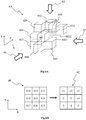
- Figure 6A shows a subset 6A of points of the 3D object of figure 1 in three dimensions and Figure 6B shows the part 6B of the depth image associated with the subset 6A, according to a non-limiting example of the present principles.
- Figure 6A shows the subset 6A of points of the 3D object and associated volume units 601, 602, 603, 604, 605, 606, 607, 608, and 609, illustrated with cubes or voxels on figure 6A .
- Cubes 601 to 609 extends onto three dimensions X, Y and Z, the axis Z representing the depth while X represents the abscissa axis and Y the ordinate axis.
- the arrows 61, 62 and 63 represent different points of view according to which the subset 6A may be seen.
- the point of view 61 enables to see the subset 6A according to the Z axis; the point of view 62 enables to see the subset 6A according to the Y axis; and the point of view 63 enables to see the subset 6A according to the X axis.
- the cubes 602 to 609 (or equivalently the points 602 to 609) may be seen as forming a neighborhood of the cube 601 (or equivalently the point 601).
- Figure 6B shows the part 6B of the depth image associated with the subset 6A.
- the part 6B of the depth image may be obtained by projecting the cubes (points) 601 to 609 according to the point of view 61 and associated axis Z.
- the part 6B forms a block of 9 pixels, 8 adjacent pixels 612 to 619 (that each corresponds/refers to the associated cubes/points 602 to 609, respectively, of the subset 6A) surrounding the pixel 611 (that corresponds/refers to the associated cube/point 601 of the subset 6A).
- the cubes/points 602 to 609 correspond to the neighborhood of the cube/point 601 as their corresponding pixels 612 to 619 of the associated depth image correspond to the adjacent pixels of the depth image surrounding the pixel 611 corresponding to the cube/point 601.
- FIG. 7A illustrates a part of the view of the subset 6A from the point of view 62, specifically the part comprising the cubes 601 and 602 and the free space between them, i.e.
- FIG. 7B Figure 7B illustrating a part of the view of the subset 6A from the point of view 63, specifically the part comprising the cubes 601 and 604 and the free space between them, i.e. the space not occupied by a cube/point of the subset 6A.
- the depth image associated with the 3D scene may be used to determine where hole(s) may be located in area(s) in the 3D scene.
- the part 6B of the depth image associated with (and obtained from) the part 6A of the points of the 3D object 10 is processed and analysed as explained hereinbelow to obtain the location of the hole(s).
- the depth information associated with the pixels 611 to 619 is used to obtain the location of the hole(s) 6001, 6002.
- the block 6C of Figure 6B shows the depth information which is associated with the pixels 611 to 619.
- Such a process is for example applied to a current pixel, namely the current pixel 611 (that is associated with the current point 601) in the example of figures 6A and 6B .
- a reference depth is associated with the current pixel 611, for example a reference depth equal to 0.
- the depth associated with the pixels 612 to 619 adjacent to the current pixel 611 is expressed in volume unit (a volume unit corresponding to a cube/voxel in the example of Figures 6A, 6B ).
- the depth associated with the adjacent pixel 612 is equal to +2 volume units; the depth associated with the adjacent pixel 613 is equal to +1 volume unit; the depth associated with the adjacent pixel 614 is equal to +3 volume units; the depth associated with the adjacent pixel 615 is equal to 0 volume unit; the depth associated with the adjacent pixel 616 is equal to -1 volume unit; the depth associated with the adjacent pixel 617 is equal to 0 volume unit; the depth associated with the adjacent pixel 618 is equal to 0 volume unit; and the depth associated with the adjacent pixel 619 is equal to +1 volume unit.
- the depth associated with the pixels may be expressed in any other metric, for example with the number of volume units separating the points (i.e.
- the associated cubes from the points of view associated with the depth image, i.e. the distance between the point of view and the points of the 3D scene (e.g. the depth associated with the current pixel 611 may be equal to 1254 volume units, the depth associated with the adjacent pixels 612 to 619 would then be 1256, 1255, 1257, 1254, 1253, 1254, 1254 and 1255, respectively).
- the depth may be expressed in centimetre or meter or in any other metric, corresponding to the distance expressed in centimetre or meter from the point of view associated with the depth image.
- Depth information associated with each adjacent pixel 612 to 619 is compared with the depth information associated with the current pixel 611. For example, the depth difference is computed between each adjacent pixel 612 to 619 and the current pixel 611.
- a first determined value e.g. 2 volume units when the depth is expressed in number of volume units
- the depth difference between the pixels 612 and 611 is equal to +2, which means that there is a hole between the corresponding cubes 601 and 602 in the 3D scene, as it clearly appears on Figure 6A (the hole corresponding to the empty space illustrated with the cube 6001).
- the depth difference between the pixels 614 and 611 is equal to +3, which means that there is a hole between the corresponding cubes 601 and 604 in the 3D scene, as it clearly appears on Figure 6A (the hole corresponding to the empty space illustrated with the cubes 6001 and 6002).
- the depth difference between the pixels 617 and 611 is equal to +0, which means that there is no hole between the corresponding cubes 607 and 601 in the 3D scene, as it clearly appears on Figure 6A (the cubes 607 and 601 contacts each other as they both belong to the plane defined by the axis X and Y; they share a face).
- the depth difference between the pixels 619 and 611 is equal to +1, which means that there is no hole between the corresponding cubes 609 and 601 in the 3D scene, as it clearly appears on Figure 6A (the cubes 609 and 601 contacts each other as they share a corner).
- each point of the 3D scene may be processed as a current point and its depth compared with the depth of its neighborhood (i.e. in the space of the associated depth image).
- a negative depth difference would be considered by taking the adjacent pixel having a negative depth difference as a new or other current pixel.
- the depth difference between two adjacent pixels is also compared with a second determined value and only the depth differences that are less than or equal to this second determined value may be considered to determine whether there is a hole between the cubes associated with the adjacent pixels.
- the comparison with the second determined value enable to ensure that the two cubes belong to a same object of the 3D scene or to a same part of the 3D object. Indeed, if the depth difference between two adjacent pixels (i.e. between the two corresponding cubes) is too big, it means that these two cubes do not belong to a same surface.
- the second determined value may for example be equal to 10, 50, or 100 volume units.
- a hole between two cubes is determined when the following conditions are fulfilled: Th 1 ⁇ d ⁇ Th 2 with d corresponding to the depth difference between the two considered pixels (and associated cubes); Th1 corresponding to the first determined value; and Th2 corresponding to the second determined value.
- additional cubes/points may be generated between two cubes/points having a depth difference d (in the depth image) fulfilling the equation 1.
- the additional cubes/points may be generating by computing their associated depth and texture from the depth and texture associated with the cubes used to determine the hole (e.g. by interpolation of the points/cubes used to determine the presence of a hole).
- the number of generated additional points may be a function of the depth difference, for example equals to d minus 1 (d - 1), when the depth difference is expressed with a number of volume units.
- the number of points/cubes generated between the points/cubes 601 and 602 is equal to 1, the depth difference between the corresponding pixels 611 and 612 of the depth image being equal to 2.
- the number of points/cubes generated between the points/cubes 601 and 604 is equal to 2, the depth difference between the corresponding pixels 611 and 614 of the depth image being equal to 3.
- the additional point/cube 6001 generated between the existing points/cubes 601 and 602 may receive as texture information the mean value of the texture values associated with the points/cubes 601 and 602 and as depth information the mean value of the depth value associated with the points/cubes 601 plus 1 (d 601 + 1).
- the additional points/cubes 6001 and 6002 generated between the existing points/cubes 601 and 604 may receive as texture information the mean value of the texture values associated with the points/cubes 601 and 604 and as depth information the depth value of the point 601 plus 1 for the cube 6001 (d 601 + 1) and the depth value of the point 601 plus 2 (d 601 + 2) for the cube 6002.
- a weight is associated with the texture of the existing points/cubes to determine the texture of an additional point/cube. For example, a greater weight may be associated with the texture of the point 601 than with the weight of the point 604 when computing the texture of the additional point 6001, as the additional point 6001 is closer to the point 601 than to the point 604. In contrast, a greater weight may be associated with the texture of the point 604 than with the weight of the point 601 when computing the texture of the additional point 6002, as the additional point 6002 is closer to the point 604 than to the point 601.
- the weight associated with a texture value when interpolating a texture value to be associated with a generated additional point may be inversely proportional to the distance (depth) separating the generating additional point from the point used to generate it.
- a weight equal to 2 may be associated with the texture of the point 601 and a weight equal to 1 may be associated with the texture of the point 604, the distance (depth difference) between the additional point 6001 and the point 601 being equal to 1 volume unit while the distance (depth difference) between the additional point 6001 and the point 604 being equal to 2 volume units.
- the texture information to be associated with a generated additional point corresponds to the texture information of one of the point used to generate it.
- the texture information of the point 601 may be applied to the generated additional point 6001 and the texture information of the point 604 may be applied to the generated additional point 6002.
- a depth difference d between a current pixel and a pixel adjacent to this current pixel
- additional points are generated only between the current pixel and the pixel adjacent pixel having the greatest depth difference d max within the interval [Th1 ;Th2].
- the point cube 6001 is generated only once using the points/cubes 601 and 604 as the depth difference (i.e.
- the greatest depth difference d max (that is less or equal to Th2) is selected among all depth differences d 612 to d 619 of the block of pixels 6B and only the adjacent pixel 614 corresponding to the greatest depth difference d max among all adjacent pixel 612 to 619 is considered with the current pixel 611 to generated additional points/cubes (from the corresponding points/cubes 601 and 604).
- Figure 8 shows a method of generating one or more points of a 3D scene implemented for example in a device 9 (described with regard to figure 9 ), according to a non-restrictive embodiment of the present principles.
- the depth information associated with a current pixel is compared with the depth information associated with pixels spatially adjacent to the current pixel in a depth image.
- the depth image is associated with existing points of a 3D scene or part of the 3D scene (e.g. existing points of a 3D object).
- Each pixel of the depth image is associated with a corresponding point of the 3D scene, the depth image being obtained by projecting the points of the 3D scene on corresponding pixels, the depth attributes of the points being stored in the depth image and associated with the corresponding pixels.
- a second operation 82 one or more additional points of the 3D scene are generated, in addition to the current point that is associated with the current pixel.
- the current point is for example generated by deprojecting the current pixel, using the parameters of the projection used to obtain the depth image from the existing points of the 3D scene.
- the one or more points are generated for example by using the current point and a point of the 3D scene obtained by deprojecting a pixel of the depth image adjacent to the current pixel, when the depth difference between the current pixel and the adjacent pixel is greater than a first value Th1 and lower than a second value Th2.
- Additional points may for example be generated for each pair of points (each pair including the current point and a point of the neighborhood of the current point corresponding to a pixel of the depth image adjacent to the current pixel) having a depth difference comprised between the first value and the second value.
- the number of additional points that are generated depend from the depth difference, the greater the depth difference, the greater the number of generated additional points.
- the adjacent pixel having the greatest depth difference with the current pixel is selected among the adjacent pixels having a depth difference with the current pixel comprised between the first value and the second value, and the additional points are generated using only the current point and the neighbour point corresponding to said adjacent pixel having the greatest depth difference.
- the attributes to be associated with the additional points are determined using the attributes of the current points and of the neighbour points (respectively corresponding to the current pixel and the adjacent pixel) used for generating the additional points.
- the texture attributes are for example obtained by interpolating the texture attributes of the current point and of the neighbour point.
- the first and second operations may be reiterated for a plurality of current pixels (or equivalently corresponding current points of the 3D scene), for example for each pixel of the depth image, or for each pixel of a part of the pixels of the depth image.
- Figure 9 shows an example of an architecture of an apparatus 9 adapted to implement at least one of the methods described with regard to figures 6 and 8 , in accordance with a non-limiting embodiment of the present principles.
- the apparatus 9 comprises following elements that are linked together by a data and address bus 91:
- the power supply is external to the device.
- the word « register » used in the specification can correspond to area of small capacity (some bits) or to very large area (e.g. a whole program or large amount of received or decoded data).
- the ROM 93 comprises at least a program and parameters.
- the ROM 93 may store algorithms and instructions to perform techniques in accordance with present principles. When switched on, the CPU 92 uploads the program in the RAM and executes the corresponding instructions.
- the RAM 94 comprises, in a register, the program executed by the CPU 92 and uploaded after switching on of the apparatus 9, input data in a register, intermediate data in different states of the method in a register, and other variables used for the execution of the method in a register.
- the implementations described herein may be implemented in, for example, a method or a process, an apparatus, a computer program product, a data stream, or a signal. Even if only discussed in the context of a single form of implementation (for example, discussed only as a method or a device), the implementation of features discussed may also be implemented in other forms (for example a program).
- An apparatus may be implemented in, for example, appropriate hardware, software, and firmware.
- the methods may be implemented in, for example, an apparatus such as, for example, a processor, which refers to processing devices in general, including, for example, a computer, a microprocessor, an integrated circuit, or a programmable logic device. Processors also include communication devices, such as, for example, computers, cell phones, portable/personal digital assistants ("PDAs”), and other devices that facilitate communication of information between end-users.
- PDAs portable/personal digital assistants
- the points of the 3D scene e.g. points of a point cloud
- associated data/attributes e.g. depth and texture of the points
- the source belongs to a set comprising:
- the decoded points or the reconstructed 3D scene is sent to a destination; specifically, the destination belongs to a set comprising:
- the apparatus 9 is configured to implement a method described in relation with at least one of the figures 6 to 8 , and belongs to a set comprising:
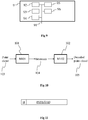
- Figure 10 shows schematically a diagram of an encoding / decoding scheme of a 3D scene, e.g. a point cloud 103, according to a particular and non-limiting embodiment of the present principles.
- the point cloud 103 is encoded into encoded data under the form of a bitstream 104 via an encoding process 101 implemented in a module M101.
- the bitstream is transmitted to a module M102 that implements a decoding process 102 to decode the encoded data to obtain a decoded point cloud 105.
- the modules M101 and M102 may be hardware, software or a combination of hardware and software.
- the point cloud 103 corresponds to a large collection of points representing an object, for instance the external surface or the external shape of the object.
- a point cloud may be seen as a vector-based structure, wherein each point has its coordinates (e.g. three-dimensional coordinates XYZ, or a depth/distance from a given point of view) and one or more components.
- An example of component is the color component that may be expressed in different color spaces, for example RGB (Red, Green and Blue) or YUV (Y being the luma component and UV two chrominance components).
- the point cloud may be a representation of the object as seen from one or more points of view.
- the point cloud may be obtained of different ways, e.g.:
- the point cloud 103 may be a dynamic point cloud that evolves with the time, i.e. the number of points may vary with the time and/or the location (e.g. at least one of the coordinates X, Y and Z) of one or more points may vary with the time.
- the evolution of the point cloud may correspond to the motion of the object represented by the point cloud and/or to any change of shape of the object or part(s) of the object.
- the point cloud 103 may be represented in a picture or in one or more groups of temporally successive pictures, each picture comprising a representation of the point cloud at a determined time 't'.
- the one or more groups of temporally successive pictures may form a video representative of at least a part of the point cloud 103.
- the encoding process 101 may for example implement intra-picture coding and/or inter-picture coding.
- Intra-picture coding is based on intra-picture prediction that exploits spatial redundancy, i.e. correlation among pixels within one picture, by calculating prediction values through extrapolation from already coded pixels for effective delta coding.
- Inter-picture coding is based on inter-picture prediction that exploits temporal redundancy.
- Temporally independently coded so-called intra pictures 'I' use only intra coding.
- the temporally coded predicted pictures 'P' (or 'B') may use intra- and inter-picture prediction.
- the decoding process 102 may for example correspond to the inverse operations of the encoding process 101 to decode the data encoded with the encoding process.
- FIG 11 shows an example of the syntax of a signal transmitted for example between two remote devices, when the data are transmitted over a packet-based transmission protocol.
- Each transmitted packet P comprises a header H and payload data PAYLOAD.
- the payload PAYLOAD may comprise at least one of the following elements:
- Figure 12 shows operations for encoding the 3D scene, e.g. the point cloud 103, according to a particular and non-limiting embodiment of the present principles.
- the operations may be part of the encoding process 101 and may be implemented by the apparatus 9 of figure 9 .
- data of a picture 20 of the point cloud is encoded by an encoder ENC1.
- the picture 20 is for example part of a group of pictures (GOP) and comprises data representative of the point cloud at a determined time 't'.
- the picture 20 may comprise a set of images, at least one of the images of the set comprising attributes that correspond to at least a part of the data of the picture 20.
- the attributes may be obtained by projecting, according to a determined projection, a part of the point cloud in each image, the attributes corresponding to the attributes of the points of the part of the point cloud projected onto said each image.
- the attributes may correspond to texture (or color) information and/or depth (or distance to a view point) information.
- the encoder ENC1 is for example compliant with a legacy encoder such as:
- the encoded data of the picture 20 may be stored and/or transmitted in the bitstream 104.
- the encoded data of the picture 20 is decoded by a decoder DEC1.
- the decoder DEC1 is compliant with the encoder ENC1, for example compliant with a legacy decoder such as:
- the attributes, encoded at operation 120, are decoded and retrieved, at operation 121, for example stored in a buffer memory, for use in the generation of a reference picture 125 associated with the picture 20.
- each image is processed as described with regard to figure 6 and/or 8 to generate points of the point cloud and for filling holes that may for example result from the encoding/decoding processes 120, 121.
- a reference picture 125 may be obtained from the corrected image(s) obtained from the module M122.
- the reference picture 125 may be used in an operation 124, implemented by a module M124.
- the operation 124 comprises for example the generation of predictors for inter prediction for the coding of one or more pictures of the point cloud, different from the picture 20 (e.g. pictures of the point cloud at determined times different from the time 't' of picture 20).
- the point cloud 103, or pictures representing the point cloud may then be encoded by referring to the reference picture 125.
- the module M124 is part of the encoder ENC1.
- a plurality of reference pictures may be obtained in a same way as the reference picture 125, each reference picture of the plurality being obtained from a specific picture representing the point cloud, the encoding of the point cloud 103 referring to one or several reference pictures.
- Figure 13 shows operations for decoding the encoded version of the point cloud 103 from the bitstream 104, according to a particular and non-limiting embodiment of the present principles.
- the operations may be part of the decoding process 102 and may be implemented by the apparatus 9 of figure 9 .
- encoded data of one or more pictures (e.g. pictures of one or more GOPs or of an intra period) of the point cloud is decoded by a decoder DEC2 from a received bitstream 104.
- the bitstream 104 comprises the encoded data of the one or more pictures.
- Each picture comprises a set of images, at least one of the images of the set comprising attributes that correspond to at least a part of the data of the picture that has been encoded.
- the attributes may be obtained by projecting, according to a first projection, a part of the point cloud in each first image, the attributes corresponding to the attributes of the points of the part of the point cloud projected onto said each first image.
- the attributes may correspond to texture (or color) information and/or depth (or distance to a view point) information.
- the decoder DEC2 may correspond to the decoder DEC1 of figure 12 and is for example compliant with a legacy decoder such as:
- the attributes decoded at operation 131 are retrieved, for example stored in a buffer memory, for use in the generation of one or more reference pictures 135, each reference picture being associated with one picture.
- each reference picture being associated with one picture.
- only one reference picture associated with one picture will be considered for clarity and conciseness purposes.
- the decoded attributes are is processed as described with regard to figure 6 and/or 8 to generate points of the point cloud and for filling holes that may for example result from the encoding/decoding processes 120, 131.
- a reference picture 135 (that may be identical to the reference picture 125 of figure 12 ) may be obtained from the picture by fusing the decoded first attributes obtained from the operation 121 with the second attributes obtained from the operation 123.
- the reference picture may comprise the same structure than the picture, i.e. the same spatial arrangement of the set of images but with different data, i.e. with the decoded first attributes and the obtained second attributes.
- a detailed description of an example of a process to obtain the reference picture is provided hereinabove with the description of figure 9 .
- the reference picture 135 may be used in an operation 134, implemented by a module M134.
- the operation 134 comprises for example the generation of the predictors for inter prediction from the decoding of the encoded data comprised in the bitstream. These data, associated to the generation of the predictor, may comprise
- a plurality of reference pictures may be obtained in a same way as the reference picture 135, each reference picture of the plurality being obtained from decoded data of a specific picture representing the point cloud, the decoding of the data of the bitstream 104 may be based on one or several reference pictures to obtain a decoded point cloud 105.
- the present disclosure is not limited to a method of generating point(s) of a 3D scene but also extends to a method for encoding and/or decoding a 3D scene / point cloud, and/or to a method and device for transmitting the bitstream obtained by the encoding of the 3D scene / point cloud and/or a method and device for receiving the bitstream obtained by the encoding of the 3D scene / point cloud.
- the present disclosure also extends to a method and device for rendering and/or displaying the decoded 3D scene / point cloud, i.e. images of the 3D object represented by the decoded point cloud, a point of view being associated with each image.
- the implementations described herein may be implemented in, for example, a method or a process, an apparatus, a software program, a data stream, or a signal. Even if only discussed in the context of a single form of implementation (for example, discussed only as a method or a device), the implementation of features discussed may also be implemented in other forms (for example a program).
- An apparatus may be implemented in, for example, appropriate hardware, software, and firmware.
- the methods may be implemented in, for example, an apparatus such as, for example, a processor, which refers to processing devices in general, including, for example, a computer, a microprocessor, an integrated circuit, or a programmable logic device. Processors also include communication devices, such as, for example, Smartphones, tablets, computers, mobile phones, portable/personal digital assistants ("PDAs”), and other devices that facilitate communication of information between end-users.
- PDAs portable/personal digital assistants
- Implementations of the various processes and features described herein may be embodied in a variety of different equipment or applications, particularly, for example, equipment or applications associated with data encoding, data decoding, view generation, texture processing, and other processing of images and related texture information and/or depth information.
- equipment include an encoder, a decoder, a post-processor processing output from a decoder, a pre-processor providing input to an encoder, a video coder, a video decoder, a video codec, a web server, a set-top box, a laptop, a personal computer, a cell phone, a PDA, a HMD (Head-Mounted Display), smart glasses and other communication devices.
- the equipment may be mobile and even installed in a mobile vehicle.
- the methods may be implemented by instructions being performed by a processor, and such instructions (and/or data values produced by an implementation) may be stored on a processor-readable medium such as, for example, an integrated circuit, a software carrier or other storage device such as, for example, a hard disk, a compact diskette (“CD"), an optical disc (such as, for example, a DVD, often referred to as a digital versatile disc or a digital video disc), a random access memory (“RAM”), or a read-only memory (“ROM”).
- the instructions may form an application program tangibly embodied on a processor-readable medium. Instructions may be, for example, in hardware, firmware, software, or a combination.
- a processor may be characterized, therefore, as, for example, both a device configured to carry out a process and a device that includes a processor-readable medium (such as a storage device) having instructions for carrying out a process. Further, a processor-readable medium may store, in addition to or in lieu of instructions, data values produced by an implementation.
- implementations may produce a variety of signals formatted to carry information that may be, for example, stored or transmitted.
- the information may include, for example, instructions for performing a method, or data produced by one of the described implementations.
- a signal may be formatted to carry as data the rules for writing or reading the syntax of a described embodiment, or to carry as data the actual syntax-values written by a described embodiment.
- Such a signal may be formatted, for example, as an electromagnetic wave (for example, using a radio frequency portion of spectrum) or as a baseband signal.
- the formatting may include, for example, encoding a data stream and modulating a carrier with the encoded data stream.
- the information that the signal carries may be, for example, analog or digital information.
- the signal may be transmitted over a variety of different wired or wireless links, as is known.
- the signal may be stored on a processor-readable medium.
Landscapes
- Engineering & Computer Science (AREA)
- Physics & Mathematics (AREA)
- Theoretical Computer Science (AREA)
- General Physics & Mathematics (AREA)
- Computer Graphics (AREA)
- Geometry (AREA)
- Software Systems (AREA)
- Computing Systems (AREA)
- Computer Vision & Pattern Recognition (AREA)
- Image Generation (AREA)
- Processing Or Creating Images (AREA)
- Image Processing (AREA)
- Length Measuring Devices By Optical Means (AREA)
- Image Analysis (AREA)
Priority Applications (11)
| Application Number | Priority Date | Filing Date | Title |
|---|---|---|---|
| EP17306345.4A EP3467782A1 (de) | 2017-10-06 | 2017-10-06 | Verfahren und vorrichtung zum erzeugen von punkten einer 3d-szene |
| CN201880076258.6A CN111386556B (zh) | 2017-10-06 | 2018-10-03 | 用于生成3d场景的点的方法和装置 |
| DK18786924.3T DK3692509T3 (da) | 2017-10-06 | 2018-10-03 | Fremgangsmåde og indretning til generering af punkter af en 3d-scene |
| RU2020115158A RU2788439C2 (ru) | 2017-10-06 | 2018-10-03 | Способ и устройство для генерации точек трехмерной (3d) сцены |
| KR1020207012438A KR102537420B1 (ko) | 2017-10-06 | 2018-10-03 | 3d 장면의 포인트들을 생성하기 위한 방법 및 디바이스 |
| HUE18786924A HUE061036T2 (hu) | 2017-10-06 | 2018-10-03 | Eljárás és eszköz 3D jelenet pontjainak generálására |
| BR112020006530-7A BR112020006530A2 (pt) | 2017-10-06 | 2018-10-03 | método e dispositivo para gerar pontos de uma cena 3d |
| US16/753,787 US11830210B2 (en) | 2017-10-06 | 2018-10-03 | Method and device for generating points of a 3D scene |
| PCT/US2018/054057 WO2019070778A1 (en) | 2017-10-06 | 2018-10-03 | METHOD AND DEVICE FOR GENERATING POINTS OF A 3D SCENE |
| JP2020518785A JP7407703B2 (ja) | 2017-10-06 | 2018-10-03 | 3dシーンの点を生成するための方法およびデバイス |
| EP18786924.3A EP3692509B1 (de) | 2017-10-06 | 2018-10-03 | Verfahren und vorrichtung zum erzeugen von punkten einer 3d-szene |
Applications Claiming Priority (1)
| Application Number | Priority Date | Filing Date | Title |
|---|---|---|---|
| EP17306345.4A EP3467782A1 (de) | 2017-10-06 | 2017-10-06 | Verfahren und vorrichtung zum erzeugen von punkten einer 3d-szene |
Publications (1)
| Publication Number | Publication Date |
|---|---|
| EP3467782A1 true EP3467782A1 (de) | 2019-04-10 |
Family
ID=60143653
Family Applications (2)
| Application Number | Title | Priority Date | Filing Date |
|---|---|---|---|
| EP17306345.4A Withdrawn EP3467782A1 (de) | 2017-10-06 | 2017-10-06 | Verfahren und vorrichtung zum erzeugen von punkten einer 3d-szene |
| EP18786924.3A Active EP3692509B1 (de) | 2017-10-06 | 2018-10-03 | Verfahren und vorrichtung zum erzeugen von punkten einer 3d-szene |
Family Applications After (1)
| Application Number | Title | Priority Date | Filing Date |
|---|---|---|---|
| EP18786924.3A Active EP3692509B1 (de) | 2017-10-06 | 2018-10-03 | Verfahren und vorrichtung zum erzeugen von punkten einer 3d-szene |
Country Status (9)
| Country | Link |
|---|---|
| US (1) | US11830210B2 (de) |
| EP (2) | EP3467782A1 (de) |
| JP (1) | JP7407703B2 (de) |
| KR (1) | KR102537420B1 (de) |
| CN (1) | CN111386556B (de) |
| BR (1) | BR112020006530A2 (de) |
| DK (1) | DK3692509T3 (de) |
| HU (1) | HUE061036T2 (de) |
| WO (1) | WO2019070778A1 (de) |
Cited By (1)
| Publication number | Priority date | Publication date | Assignee | Title |
|---|---|---|---|---|
| EP3742404A1 (de) * | 2019-05-22 | 2020-11-25 | Sony Interactive Entertainment Inc. | Inhaltscodierungssystem und -verfahren |
Families Citing this family (8)
| Publication number | Priority date | Publication date | Assignee | Title |
|---|---|---|---|---|
| US10907954B2 (en) * | 2018-09-28 | 2021-02-02 | Hand Held Products, Inc. | Methods and systems for measuring dimensions of a 2-D object |
| US20230290006A1 (en) * | 2020-09-03 | 2023-09-14 | Lg Electronics Inc. | Point cloud data transmission device, point cloud data transmission method, point cloud data reception device, and point cloud data reception method |
| US11823327B2 (en) | 2020-11-19 | 2023-11-21 | Samsung Electronics Co., Ltd. | Method for rendering relighted 3D portrait of person and computing device for the same |
| WO2022119304A1 (ko) * | 2020-12-01 | 2022-06-09 | 현대자동차주식회사 | 적응적 데드존 양자화를 이용하는 포인트 클라우드 코딩 장치 및 방법 |
| WO2022149810A1 (ko) * | 2021-01-06 | 2022-07-14 | 엘지전자 주식회사 | 포인트 클라우드 데이터 송신 장치, 포인트 클라우드 데이터 송신 방법, 포인트 클라우드 데이터 수신 장치 및 포인트 클라우드 데이터 수신 방법 |
| KR102665543B1 (ko) | 2021-02-22 | 2024-05-16 | 한국전자통신연구원 | 다시점 영상으로부터의 깊이지도 생성 장치 및 방법 |
| US11756281B1 (en) * | 2023-03-14 | 2023-09-12 | Illuscio, Inc. | Systems and methods for splat filling a three-dimensional image using semi-measured data |
| US11935209B1 (en) | 2023-07-24 | 2024-03-19 | Illuscio, Inc. | Systems and methods for dynamic backfilling of a three-dimensional object |
Citations (1)
| Publication number | Priority date | Publication date | Assignee | Title |
|---|---|---|---|---|
| US20090174710A1 (en) * | 2008-01-08 | 2009-07-09 | Samsung Electronics Co., Ltd. | Modeling method and apparatus |
Family Cites Families (34)
| Publication number | Priority date | Publication date | Assignee | Title |
|---|---|---|---|---|
| US7015926B2 (en) * | 2004-06-28 | 2006-03-21 | Microsoft Corporation | System and process for generating a two-layer, 3D representation of a scene |
| US7576737B2 (en) * | 2004-09-24 | 2009-08-18 | Konica Minolta Medical & Graphic, Inc. | Image processing device and program |
| RU2407224C2 (ru) | 2005-04-19 | 2010-12-20 | Конинклейке Филипс Электроникс Н.В. | Восприятие глубины |
| JP5167248B2 (ja) * | 2006-05-11 | 2013-03-21 | プライムセンス リミテッド | 深度マップによるヒューマノイド形状のモデル化 |
| US9645240B1 (en) * | 2010-05-10 | 2017-05-09 | Faro Technologies, Inc. | Method for optically scanning and measuring an environment |
| US20110304618A1 (en) * | 2010-06-14 | 2011-12-15 | Qualcomm Incorporated | Calculating disparity for three-dimensional images |
| JP5858380B2 (ja) * | 2010-12-03 | 2016-02-10 | 国立大学法人名古屋大学 | 仮想視点画像合成方法及び仮想視点画像合成システム |
| KR101210625B1 (ko) * | 2010-12-28 | 2012-12-11 | 주식회사 케이티 | 빈공간 채움 방법 및 이를 수행하는 3차원 비디오 시스템 |
| CN102055982B (zh) | 2011-01-13 | 2012-06-27 | 浙江大学 | 三维视频编解码方法及装置 |
| US9053571B2 (en) * | 2011-06-06 | 2015-06-09 | Microsoft Corporation | Generating computer models of 3D objects |
| US9471988B2 (en) * | 2011-11-02 | 2016-10-18 | Google Inc. | Depth-map generation for an input image using an example approximate depth-map associated with an example similar image |
| US9282915B2 (en) * | 2011-11-29 | 2016-03-15 | St. Jude Medical, Atrial Fibrillation Division, Inc. | Method and system for generating and/or repairing a surface model of a geometric structure |
| WO2013111994A1 (en) * | 2012-01-26 | 2013-08-01 | Samsung Electronics Co., Ltd. | Image processing method and apparatus for 3d video |
| US8712147B2 (en) * | 2012-02-03 | 2014-04-29 | Harris Corporation | Fractal method for detecting and filling data gaps within LiDAR data |
| EP2876609B1 (de) * | 2012-07-23 | 2017-12-13 | Fujitsu Limited | Formdatenerzeugungsprogramm, formdatenerzeugungsverfahren und vorrichtung zur erzeugung von formdaten |
| US9811880B2 (en) * | 2012-11-09 | 2017-11-07 | The Boeing Company | Backfilling points in a point cloud |
| KR20150117662A (ko) * | 2013-02-12 | 2015-10-20 | 톰슨 라이센싱 | 깊이 맵의 컨텐츠를 강화하기 위한 방법 및 디바이스 |
| US9756359B2 (en) * | 2013-12-16 | 2017-09-05 | Qualcomm Incorporated | Large blocks and depth modeling modes (DMM'S) in 3D video coding |
| US9171403B2 (en) * | 2014-02-13 | 2015-10-27 | Microsoft Technology Licensing, Llc | Contour completion for augmenting surface reconstructions |
| US9292961B1 (en) * | 2014-08-26 | 2016-03-22 | The Boeing Company | System and method for detecting a structural opening in a three dimensional point cloud |
| US9792531B2 (en) * | 2015-09-16 | 2017-10-17 | Siemens Healthcare Gmbh | Intelligent multi-scale medical image landmark detection |
| GB2543749A (en) * | 2015-10-21 | 2017-05-03 | Nokia Technologies Oy | 3D scene rendering |
| CN105825544B (zh) * | 2015-11-25 | 2019-08-20 | 维沃移动通信有限公司 | 一种图像处理方法及移动终端 |
| US20170186223A1 (en) * | 2015-12-23 | 2017-06-29 | Intel Corporation | Detection of shadow regions in image depth data caused by multiple image sensors |
| US10192103B2 (en) * | 2016-01-15 | 2019-01-29 | Stereovision Imaging, Inc. | System and method for detecting and removing occlusions in a three-dimensional image |
| WO2017162594A1 (en) * | 2016-03-21 | 2017-09-28 | Thomson Licensing | Dibr with depth map preprocessing for reducing visibility of holes by locally blurring hole areas |
| TW201805894A (zh) * | 2016-05-06 | 2018-02-16 | 國立臺灣大學 | 三維渲染方法以及三維繪圖處理裝置 |
| US10074160B2 (en) * | 2016-09-30 | 2018-09-11 | Disney Enterprises, Inc. | Point cloud noise and outlier removal for image-based 3D reconstruction |
| US9972067B2 (en) * | 2016-10-11 | 2018-05-15 | The Boeing Company | System and method for upsampling of sparse point cloud for 3D registration |
| JP2020500385A (ja) * | 2016-10-20 | 2020-01-09 | ロボ−チーム ホーム リミテッド | 人間追跡ロボット |
| US10176589B2 (en) * | 2017-01-31 | 2019-01-08 | Mitsubishi Electric Research Labroatories, Inc. | Method and system for completing point clouds using planar segments |
| CN108694740A (zh) * | 2017-03-06 | 2018-10-23 | 索尼公司 | 信息处理设备、信息处理方法以及用户设备 |
| US10803561B2 (en) * | 2017-06-02 | 2020-10-13 | Wisconsin Alumni Research Foundation | Systems, methods, and media for hierarchical progressive point cloud rendering |
| US10509413B2 (en) * | 2017-09-07 | 2019-12-17 | GM Global Technology Operations LLC | Ground reference determination for autonomous vehicle operations |
-
2017
- 2017-10-06 EP EP17306345.4A patent/EP3467782A1/de not_active Withdrawn
-
2018
- 2018-10-03 BR BR112020006530-7A patent/BR112020006530A2/pt unknown
- 2018-10-03 US US16/753,787 patent/US11830210B2/en active Active
- 2018-10-03 CN CN201880076258.6A patent/CN111386556B/zh active Active
- 2018-10-03 HU HUE18786924A patent/HUE061036T2/hu unknown
- 2018-10-03 DK DK18786924.3T patent/DK3692509T3/da active
- 2018-10-03 KR KR1020207012438A patent/KR102537420B1/ko active IP Right Grant
- 2018-10-03 WO PCT/US2018/054057 patent/WO2019070778A1/en unknown
- 2018-10-03 EP EP18786924.3A patent/EP3692509B1/de active Active
- 2018-10-03 JP JP2020518785A patent/JP7407703B2/ja active Active
Patent Citations (1)
| Publication number | Priority date | Publication date | Assignee | Title |
|---|---|---|---|---|
| US20090174710A1 (en) * | 2008-01-08 | 2009-07-09 | Samsung Electronics Co., Ltd. | Modeling method and apparatus |
Non-Patent Citations (7)
| Title |
|---|
| BRIAN CURLESS ET AL: "A volumetric method for building complex models from range images", COMPUTER GRAPHICS PROCEEDINGS. SIGGRAPH '96, ACM, NEW YORK, US, August 1996 (1996-08-01), pages 303 - 312, XP058220108, ISBN: 978-0-89791-746-9, DOI: 10.1145/237170.237269 * |
| DAEYOUNG KIM ET AL: "High-quality depth map up-sampling robust to edge noise of range sensors", IMAGE PROCESSING (ICIP), 2012 19TH IEEE INTERNATIONAL CONFERENCE ON, IEEE, 30 September 2012 (2012-09-30), pages 553 - 556, XP032333235, ISBN: 978-1-4673-2534-9, DOI: 10.1109/ICIP.2012.6466919 * |
| G.H. TARBOX ET AL: "IVIS: an integrated volumetric inspection system", PROCEEDINGS OF THE 1994 SECOND CAD-BASED VISION WORKSHOP: FEBRUARY 8 - 11, 1994, CHAMPION, PENNSYLVANIA, January 1994 (1994-01-01), Piscataway, NJ, USA, pages 220 - 227, XP055480240, ISBN: 978-0-8186-5310-0, DOI: 10.1109/CADVIS.1994.284498 * |
| JIANXIONG XIAO ET AL: "Reconstructing the World s Museums", 7 October 2012, COMPUTER VISION ECCV 2012, SPRINGER BERLIN HEIDELBERG, BERLIN, HEIDELBERG, PAGE(S) 668 - 681, ISBN: 978-3-642-33717-8, XP047018590 * |
| JULIEN RICARD ET AL: "CGI-based dynamic point cloud test content", 117. MPEG MEETING; 16-1-2017 - 20-1-2017; GENEVA; (MOTION PICTURE EXPERT GROUP OR ISO/IEC JTC1/SC29/WG11),, no. m40050, 12 January 2017 (2017-01-12), XP030068395 * |
| MATTHEW BERGER ET AL., STATE OF THE ART IN SURFACE RECONSTRUCTION FROM POINT CLOUDS, 2014 |
| MATTHEW BERGER ET AL: "State of the Art in Surface Reconstruction from Point Clouds", EUROGRAPHICS STAR REPORT, April 2014 (2014-04-01), pages 161 - 185, XP055367964, Retrieved from the Internet <URL:https://hal.inria.fr/docs/01/01/77/00/PDF/star_author.pdf> [retrieved on 20170426], DOI: 10.2312/egst.20141040> * |
Cited By (1)
| Publication number | Priority date | Publication date | Assignee | Title |
|---|---|---|---|---|
| EP3742404A1 (de) * | 2019-05-22 | 2020-11-25 | Sony Interactive Entertainment Inc. | Inhaltscodierungssystem und -verfahren |
Also Published As
| Publication number | Publication date |
|---|---|
| US11830210B2 (en) | 2023-11-28 |
| JP2020536325A (ja) | 2020-12-10 |
| EP3692509A1 (de) | 2020-08-12 |
| JP7407703B2 (ja) | 2024-01-04 |
| CN111386556A (zh) | 2020-07-07 |
| HUE061036T2 (hu) | 2023-05-28 |
| KR102537420B1 (ko) | 2023-05-26 |
| WO2019070778A1 (en) | 2019-04-11 |
| RU2020115158A (ru) | 2021-11-08 |
| BR112020006530A2 (pt) | 2020-10-06 |
| CN111386556B (zh) | 2024-03-12 |
| KR20200057077A (ko) | 2020-05-25 |
| US20200258247A1 (en) | 2020-08-13 |
| DK3692509T3 (da) | 2023-01-09 |
| EP3692509B1 (de) | 2022-12-07 |
Similar Documents
| Publication | Publication Date | Title |
|---|---|---|
| EP3462415A1 (de) | Verfahren und vorrichtung zur modifizierung von attributen von punkten einer 3d-szene | |
| EP3692509B1 (de) | Verfahren und vorrichtung zum erzeugen von punkten einer 3d-szene | |
| KR102594003B1 (ko) | 볼류메트릭 비디오를 인코딩/디코딩하기 위한 방법, 장치 및 스트림 | |
| US20190108655A1 (en) | Method and apparatus for encoding a point cloud representing three-dimensional objects | |
| EP3692510B1 (de) | Verfahren und vorrichtung zur rekonstruktion einer punktwolke, die ein 3d-objekt repräsentiert | |
| US20200302653A1 (en) | A method and apparatus for encoding/decoding the geometry of a point cloud representing a 3d object | |
| US11019363B2 (en) | Method and device for encoding a point cloud | |
| US20200211232A1 (en) | A method and apparatus for encoding/decoding a point cloud representing a 3d object | |
| EP3429206A1 (de) | Verfahren und vorrichtung zur codierung einer punktwolke | |
| US20200252657A1 (en) | A method and apparatus for encoding/decoding the geometry of a point cloud representing a 3d object | |
| US20200302652A1 (en) | A method and apparatus for encoding/decoding a colored point cloud representing the geometry and colors of a 3d object | |
| US11765397B2 (en) | Method and apparatus for encoding/decoding the colors of a point cloud representing a 3D object | |
| RU2788439C2 (ru) | Способ и устройство для генерации точек трехмерной (3d) сцены |
Legal Events
| Date | Code | Title | Description |
|---|---|---|---|
| PUAI | Public reference made under article 153(3) epc to a published international application that has entered the european phase |
Free format text: ORIGINAL CODE: 0009012 |
|
| AK | Designated contracting states |
Kind code of ref document: A1 Designated state(s): AL AT BE BG CH CY CZ DE DK EE ES FI FR GB GR HR HU IE IS IT LI LT LU LV MC MK MT NL NO PL PT RO RS SE SI SK SM TR |
|
| AX | Request for extension of the european patent |
Extension state: BA ME |
|
| STAA | Information on the status of an ep patent application or granted ep patent |
Free format text: STATUS: THE APPLICATION IS DEEMED TO BE WITHDRAWN |
|
| 18D | Application deemed to be withdrawn |
Effective date: 20191011 |