EP3021286B1 - Vorrichtung und Verfahren zur Berechnung von Schatten in einer 3D-Szene - Google Patents
Vorrichtung und Verfahren zur Berechnung von Schatten in einer 3D-Szene Download PDFInfo
- Publication number
- EP3021286B1 EP3021286B1 EP14306804.7A EP14306804A EP3021286B1 EP 3021286 B1 EP3021286 B1 EP 3021286B1 EP 14306804 A EP14306804 A EP 14306804A EP 3021286 B1 EP3021286 B1 EP 3021286B1
- Authority
- EP
- European Patent Office
- Prior art keywords
- depth
- depth map
- pixel
- surface element
- minimum
- Prior art date
- Legal status (The legal status is an assumption and is not a legal conclusion. Google has not performed a legal analysis and makes no representation as to the accuracy of the status listed.)
- Active
Links
Images


Classifications
-
- G—PHYSICS
- G06—COMPUTING OR CALCULATING; COUNTING
- G06T—IMAGE DATA PROCESSING OR GENERATION, IN GENERAL
- G06T15/00—Three-dimensional [3D] image rendering
- G06T15/50—Lighting effects
- G06T15/60—Shadow generation
-
- G—PHYSICS
- G06—COMPUTING OR CALCULATING; COUNTING
- G06T—IMAGE DATA PROCESSING OR GENERATION, IN GENERAL
- G06T15/00—Three-dimensional [3D] image rendering
- G06T15/06—Ray-tracing
Definitions
- the invention relates to the domain of image rendering in the representation of three-dimensional scenes, and concerns more especially shadow computing. It pertains to Computer Generated Image (CGI or 3D-CGI), notably for games and VFX (Visual Effects) pre-visualisation and VFX production.
- CGI Computer Generated Image
- 3D-CGI Computer Generated Image
- VFX Visual Effects
- the rendering of high-quality shadows in a 3D scene is currently achieved by using ray-tracing techniques, which allow precise visibility tests between light sources and surfaces. Those tests consist in casting a ray towards light sources and determine whether or not it intersects an element of the scene. If an intersection is found, the point is considered in shadow.
- That method suffers however some following drawbacks.
- many different triangle IDs may be stored locally in a shadow map, especially in presence of unorganized geometry (trees or leaves, for instance). Storing such unorganized triangle IDs leads to scattered memory accesses that have proved to be inefficient on GPU architecture. This is suspected to be the bottleneck of their method, since the reported speed-up does not show so much improvement in rendering times. Namely, best reported speed up amounts to a factor of around 1.46 over a full ray-tracing solution.
- the use of the triangle coverage flag is prone to errors for inclined surfaces.
- that technique performs excessive ray-tracing computations in areas lying in shadow edges. Computational overhead becomes even prohibitive in presence of models with geometry density similar or slightly greater than the shadow map resolution.
- the purpose of the present disclosure is to overcome the disadvantages of the prior art, by offering potentially increased computing efficiency with maintained good-level rendering precision.
- An object of the present disclosure is notably a hybrid rendering of shadows possibly enabling to overcome the above-mentioned drawbacks.
- Such a technology can potentially provide, in its best embodiments, a fast and precise solution, which does not introduce any artefact and achieves real-time performances in complex scenes at quality close to full ray-tracing methods.
- the present disclosure relates to a graphics processing device configured to compute shadow in a three-dimensional scene lighted by at least one light source, based on at least one depth map comprising a plurality of elements, that depth map being associated with a two-dimensional bounded space adapted to render an image of the scene according to a point of view of the light source(s).
- the graphics processing device comprises at least one processor configured for:
- processor(s) is/are further configured to:
- the graphics processing device of the present disclosure is to be understood preferably as an apparatus, or a physical part of an apparatus, designed, configured and/or adapted for performing the mentioned functions and produce the mentioned effects or results. In alternative implementations, however, it is embodied as a set of apparatus or physical parts of apparatus, whether grouped in a same machine or in different, possibly remote, machines. In the latter case, the graphics processing device of the present disclosure amounts to a system.
- the graphics processing device of the present disclosure includes one or several GPUs, which comprise the processor(s) of the device.
- the device is made of one or several circuits inside a GPU.
- the device is configured for cooperating with GPUs.
- adapted and “configured” are further used in the definition of the present disclosure as broadly encompassing initial configuration, later adaptation or complementation of the device, or any combination thereof alike, whether effected through material or software means (including firmware).
- an element of the 3D scene is called a fragment or a point when positioning in the space of the scene (the world space), while the same element visible from the point of view associated with the depth map is called pixel when positioning in the space of the depth map.
- a point (fragment) visible from the point of view (light source) associated with the depth map and the corresponding pixel in the depth map refer thus to one and a same element of the scene and may mixed up in some parts of the description.
- the encoding of the surface elements into the depth map elements are advantageously carried out by a fragment shader of a GPU rendering pipeline.
- this is effected in a computing kernel in image space using a G-buffer (Geometry buffer), such as with computing platforms involving OpenCL (Open Computing Language), CUDA or an OpenGL or Direct3D Compute Shader (shader stage that is used for computing arbitrary information).
- G-buffer GPU-buffer
- a possibly efficient lit/shadowed classification is offered by the present device, relying notably on preliminary depth comparison with a reference value, consisting in a previously computed minimum depth for the considered depth map element.
- the knowledge of that minimum depth is based on information pertaining to vertices coordinates and local depth variation stored in that element, the latter being preferably obtained by means of the solutions disclosed in WO 2014/124870 A1 and WO 2014/124871 A2 to Thomson Licensing.
- the information on local depth variation is advantageously established (i.e. computed or generated) by a GPU during the rasterization process of the considered surface element(s).
- the information representative of the variation of depth in the considered depth map element, for a given surface element is preferably established from depth information associated with the centers of depth map elements neighboring the considered depth map element.
- the information representative of the variation of depth for the considered depth map element along an axis is established from the depth information associated with the center of that element and with the center of another element advantageously adjacent to that element along that axis, by taking into account the distance separating the centers of those depth map elements along that axis.
- the depth information is preferably obtained for the two axes x and y corresponding to the space (x, y) of the depth map.
- the information representative of the variation of depth pertaining to a given surface element is obtained by projecting that surface element into a tridimensional space of an orthographic camera associated with the depth map. This provides a function representative of the plane associated with the surface element in the 3D space (x, y, z) of the orthographic camera, and consequently the information representative of the variation of depth z along the x axis and/or the y axis.
- the latter are fully or partly expressed under the form of slope angles, which are advantageously encoded in odd power functions (e.g. x 3 or x 5 ).
- odd power functions e.g. x 3 or x 5
- This can enable to keep a good accuracy with limited depth map storage, though the variations of depth tend to be significantly small in presence of front facing surfaces (i.e. surfaces of object(s) having a normal parallel or roughly parallel with the viewing direction passing through the center of the depth map element) and conversely very large in presence of grazing angle surfaces (i.e. surfaces of object(s) of the scene having a normal perpendicular or roughly perpendicular to the normal of the depth map).
- the present disclosure contrasts notably with the teaching of those publications in that instead of computing repeatedly the depth information taking into account the variation of depth for each processed fragment, the computed minimum depth is available for the whole depth map element. It further enables to take the boundaries of the surface elements into account without requiring the establishment of frontiers between objects as described in WO 2014/124870 A1 . Those differences can potentially lead to significant processing gains, without jeopardizing in any way the accuracy of the outputs.
- the present device in appropriate implementations appears to avoid or significantly reduce scattered random accesses into GPU memory.
- This can be due notably to explicitly storing the entire definition of the surface elements in the depth map elements - including the coordinates of vertices as well as depth and local depth variation.
- shadow ray intersection can be performed directly against surface elements available for the depth map elements - e.g. triangles stored in texels. This enables to access information on a surface element through a single texture fetch, instead of deferred random accesses using surface element IDs.
- the information representative of a depth for a surface element is computed at the center of the considered depth map element.
- the minimum depth computed notably from the coordinates of vertices corresponds preferably to the effective minimum value reached by the depth for the considered surface element over the depth map element.
- the graphics processing device of the present disclosure further makes possible easy implementation on graphics hardware and/or on production renderers.
- the processor(s) is/are further configured to classify the pixel as uncertain if that pixel is not classified as lit and is not classified as shadowed, and to trace a ray having as origin a scene fragment of the three-dimensional scene corresponding to that pixel toward said point of view as to determine whether said pixel is lit.
- the processor(s) is/are further exploiting spatial acceleration structure for ray tracing, leading to grouping objects of the 3D scene according to a spatial acceleration scheme with hierarchization.
- That spatial acceleration advantageously relies on BVH (Bounding Volume Hierarchy), LBVH (Linear BVH), BSP trees (Binary Space Partitioning) - notably k-d trees - or Octrees structures.
- BVH Binary Volume Hierarchy
- LBVH Linear BVH
- BSP trees Binary Space Partitioning
- Such structures map very well on GPU memory with good locality of data.
- the processor(s) is/are further preferably configured for tracing the ray only up to a distance to the point of view corresponding to the minimum depth associated with the depth map element in which that pixel is located.
- the processor(s) is/are further configured to compute the minimum depth for the considered depth map element also from the coordinates of vertices and the information representative of depth and of local depth variation stored in the neighbor depth map elements for the surface element(s) associated with the neighbor depth map elements.
- That extension can enable still increased rendering accuracy, especially in presence of small or thin surface elements. Indeed, surface elements stored in the vicinity of the considered depth map element but overlapping the latter can thereby be taken into account in the filtering based on the minimum depth.
- the processor(s) is/are further configured:
- the neighbor depth map elements consist in eight neighbor depth map elements surrounding the considered depth map element(s).
- each of the depth map elements having a center the processor(s) is/are further configured for:
- Conservative rasterization is particularly useful for considering surface elements, such as e.g. triangles, having a size that is less than a depth map element. They may represent thin geometry structures such as tree branches, but also surface elements viewed from grazing angles, which are very important to be considered as they are responsible for the shadow silhouette.
- Surface elements such as e.g. triangles
- They may represent thin geometry structures such as tree branches, but also surface elements viewed from grazing angles, which are very important to be considered as they are responsible for the shadow silhouette.
- Principles and particular implementations of conservative rasterization have been described and discussed notably in above cited reference by Hertel et al. dated 2009 and in a publication by J. Hasselgren, T. Akenine-Möller and L. Ohlsson, "Conservative rasterization", in the book GPU Gems 2, 2005, pages 677-690 .
- a person skilled in the art will thus be aware of multiple different and efficient ways of implementing conservative rasterization with the present device.
- the expansion of the surface elements is preferably such that any surface element projected at least partly into the depth map element, even though not covering the center of that depth map element, is fully taken into account. Conversely, that expansion is preferably limited so as to avoid associating surface elements with depth map elements into which they are not projected.
- the expansion can be determined in different ways, as known to a person skilled in the art. Especially, the edges of the expanded surface elements are advantageously moved toward their normal direction, for example by a length equal to 0.5 time the width of a depth map element.
- Conservative rasterization enables to extend the coverage of the surface elements to depth map elements that would have not been considered otherwise, due to having centers not covered by those surface elements.
- conservative rasterization is preferably combined with the recording of the relevant geometric information (coordinates of vertices and information on depth and local depth variation), which pertains to the surface element having the smallest depth at the center of the considered depth map element.
- relevant geometric information coordinates of vertices and information on depth and local depth variation
- the depth at the center of the depth map element is preferably estimated from linear interpolation based on depth variations within that surface element.
- conservative rasterization is combined with the recording of the relevant geometric information (coordinates of vertices and information on depth and local depth variation), which pertains to the surface element having the smallest depth over the whole depth map element.
- This implementation decreases the number of uncertain pixels. Indeed, it is consistent with the stored minimum depth value, since corresponding to the same surface element, and avoids the existence of view samples for which the depth is inferior to the minimum depth value but superior to the smallest depth value over the considered depth map element for the stored surface element. It requires however some specific adaptations with respect to existing systems.
- Conservative rasterization of the depth map for shadow computing can further allow rapid classification of lit area. In appropriate implementations, it can guarantee that the depth of closest visible surface element is written whatever the coverage of that surface element inside a depth map element. Accordingly, if the depth of a view sample projected in light space is less than, or equal to, the minimum depth stored in the depth map element, it can then ensure that the corresponding pixel is fully lit.
- Computing the conservative expansion of the surface elements is preferably carried out at the stage of a geometry shader in a GPU rendering pipeline.
- the processor(s) is/are further configured for computing the minimum depth(s) at at least one point of that depth map element and of the projection in the space of the depth map of the surface element(s), called a closest point. That closest point is determined by means of a gradient of decreasing depth variation in the space of the depth map for the surface element, given by the information representative of local depth variation.
- the closest point is advantageously determined by:
- the processor(s) is/are configured for determining the minimum depth:
- the processor(s) is/are configured for determining the minimum depth if no intersection is found between the closest edge and the sides of the depth map element:
- the present disclosure also pertains to a method for graphics processing adapted to compute shadow in a three-dimensional scene lighted by at least one light source, based on at least one depth map comprising a plurality of elements, that depth map being associated with a two-dimensional bounded space adapted to render an image of the scene according to a point of view of the light source.
- the graphics processing method comprising:
- the method for graphics processing further includes:
- This computer program can have any form, and notably be embedded in a graphics processing device or a GPU according to the present disclosure. In alternative embodiments, it is available separately from an apparatus, and configured to be implemented within that apparatus so as to allow the execution of the process for graphics processing compliant with the present disclosure. This can be done either via a tangible support carrying the computer program or via local or remote downloading. In particular, the computer program can be available as flashing firmware, enabling to update a graphics processing apparatus.
- Such a non-transitory program storage device can be, without limitation, an electronic, magnetic, optical, electromagnetic, infrared, or semiconductor device, or any suitable combination of the foregoing. It is to be appreciated that the following, while providing more specific examples, is merely an illustrative and not exhaustive listing as readily appreciated by one of ordinary skill in the art: a portable computer diskette, a hard disk, a ROM (read-only memory), an EPROM (Erasable Programmable ROM) or a Flash memory, a portable CD-ROM (Compact-Disc ROM).
- a GPU can include itself several warps, thereby providing potentially as a whole a high number of threads.
- a GPU in a specific embodiment comprises 24 warps, each of which including 4 blocks of 8 threads - which makes 768 threads in the GPU.
- the GPU comprises a unique warp including 16 blocks of 32 threads - which amounts to 512 threads in the GPU.
- the apparatus 1 corresponds for example to a personal computer (PC), a laptop, a tablet, a smartphone or a games console - especially specialized games consoles producing and displaying images live.
- PC personal computer
- laptop a laptop
- tablet a tablet
- smartphone a games console - especially specialized games consoles producing and displaying images live.
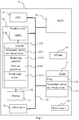
- the apparatus 1 comprises the following elements, connected to each other by a bus 15 of addresses and data that also transports a clock signal:
- the apparatus 1 also comprises a display device 13 of display screen type directly connected to the graphics card 12 to display synthesized images calculated and composed in the graphics card, for example live.
- a dedicated bus to connect the display device 13 to the graphics card 12 offers the advantage of having much greater data transmission bitrates and thus reducing the latency time for the displaying of images composed by the graphics card.
- a display device is external to apparatus 1 and is connected thereto by a cable or wirelessly for transmitting the display signals.
- the apparatus 1, for example the graphics card 12, comprises an interface for transmission or connection adapted to transmit a display signal to an external display means such as for example an LCD or plasma screen or a video-projector.
- the RF unit 19 can be used for wireless transmissions.
- register used in the description of memories 121, 16, and 17 designates in each of the memories mentioned, both a memory zone of low capacity (some binary data) as well as a memory zone of large capacity (enabling a whole program to be stored or all or part of the data representative of data calculated or to be displayed).
- the registers represented for GRAM 121 can be arranged and constituted in any manner, and each of them does not necessarily correspond to adjacent memory locations and can be distributed otherwise (which covers notably the situation in which one register includes several smaller registers).
- the microprocessor 11 When switched-on, the microprocessor 11 loads and executes the instructions of the program contained in the RAM 17.
- the random access memory 17 notably comprises:
- the algorithms implementing the steps of the method specific to the present disclosure and described hereafter are stored in the memory GRAM 121 of the graphics card 12 associated with the apparatus 1 implementing these steps.
- the graphic processors 120 of the graphics card 12 load these parameters into the GRAM 121 and execute the instructions of these algorithms in the form of microprograms of "shader" type using HLSL (High Level Shader Language) language or GLSL (OpenGL Shading Language) for example.
- HLSL High Level Shader Language
- GLSL OpenGL Shading Language
- the random access memory GRAM 121 comprises notably:
- At least some of the data pertaining to primitives are stored in the RAM 17 and processed by the microprocessor 11.
- This variant causes greater latency time in the composition of an image comprising a representation of the environment composed from microprograms contained in the GPUs 120 as the data must be transmitted from the graphics card to the random access memory 17 passing by the bus 15, for which the transmission capacities are generally inferior to those available in the graphics card for transmission of data from the GPUs 120 to the GRAM 121 and vice-versa.
- a depth map processed by apparatus 1 corresponds advantageously to an array of L lines and M columns of elements (L and M being integers greater than 0) and is associated with a scene which is rendered in one or more images.
- the number of elements comprised in the depth map corresponds for example to the number of pixels of the image(s) of the scene.
- the depth map is advantageously enriched with information representative of the variation of depth and with minimum depth values, as will be explained below.
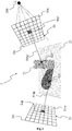
- Figure 2 shows a scene 2 rendered in an image 21 with an associated depth map 20 dedicated to shadows computing (also called shadow map), according to a particular and non-limitative embodiment.
- the image 21 represents the scene 2 as viewed from a given point of view (also called camera field of view, not represented on Figure 2 ) and the depth map 20 is generated according to another point of view 200, associated with a light source L.
- the scene corresponds for example to a virtual scene and comprises several virtual objects, i.e. a first object 22 and a second object 23.
- the objects 22 and 23 are modelled according to any method known to those skilled in the art, for example by polygonal modelling, in which the model is assimilated with a set of polygons (mesh elements) each defined by the list of summits and edges that compose it, by NURBS (Non Uniform Rational Basic Spline) type curve modelling in which the model is defined by a set of curves created via control vertices, by modelling by subdivision of surfaces.
- polygonal modelling in which the model is assimilated with a set of polygons (mesh elements) each defined by the list of summits and edges that compose it
- NURBS Non Uniform Rational Basic Spline
- virtual object any virtual representation (obtained by modelling) of an object (real or fictitious) composing a real environment / real scene (for example the ground, a house or a house front, a person, a car, a tree, that is to say any element composing an environment such as a part of a house, a street, a town, the countryside, etc.) or an imaginary element.
- a real environment / real scene for example the ground, a house or a house front, a person, a car, a tree, that is to say any element composing an environment such as a part of a house, a street, a town, the countryside, etc.
- Each object 22, 23 of the scene 2 is characterized by a surface covering it, the surface of each object having reflectance properties (corresponding to the proportion of incident light reflected by the surface in one or several directions) that are specific to it.
- the depth map 20 comprises n elements 201 ... 20p' ... 20n, n being an integer greater than 0 that defines the resolution of the depth map 20, the resolution being for example equal to 512x512 pixels, 1024x1024 pixels or 4096x4096 pixels.
- Depth information is associated with each element of the depth map 20. This depth information corresponds to the distance between the point of view 200 and the closest visible fragment of the scene 2 along a viewing direction passing through an element of the depth map, this element of the depth map being associated with the closest visible fragment of the scene.
- the depth information associated with this element 20p' corresponds to the distance between the point of view 200 and the fragment P' 221 of the scene 2 along the viewing direction 200p' having as origin the point of view 200 and passing through the element 20p'.
- the fragment P' 221 corresponds to the first element of the scene crossed by the viewing direction 200p' when starting from the point of view 200.
- the depth information is associated with the corresponding element of the depth map.
- the depth information is completed for each element of the depth map 20 with information representative of the variation of depth inside that element and with a minimum depth value.
- those complements are available for only part of the depth map 20.
- the image 21 comprises m pixels 211 ... 21p ... 21 m, m being an integer greater than 0 that defines the resolution of the image 21.
- m is different from n, for example n is greater than m or m is greater than n (the resolution of the depth map 20 is for example 512x512 pixels, 1024x1024 pixels or 4096x4096 pixels whereas the resolution for the image 21 is for example 1024x768 pixels, 1280x720 pixels or 1920x1200 pixels).
- m is equal to n, both depth map 20 and image 21 having the same resolution.
- Attributes are advantageously associated with each pixel of the image 21, the attributes comprising for example color information (for example RGB information) and/or the translucent character of the fragment of the scene associated with a pixel of the image.
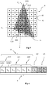
- each texel 40 having its center 41 covered by the expanded triangle 520 is associated with the latter.
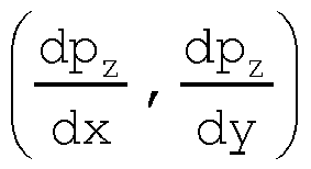
- geometric information regarding triangle 510 is explicitly stored in texel 40 in a compact form, including its vertices V0, V1, V2, its depth p z evaluated or extrapolated at the center 41 of texel 40 and the partial derivatives of its depth dp z dx , dp z dy ⁇ representing its depth gradient.
- the texels used for storing that geometric information are in particular implementations RGBA texels of the depth map 20.
- the texel 400 has its center 410 covered by extended triangle 520, though the original triangle 510 does not reach that center 410 but overlaps it partly. Due to conservative rasterization, the triangle 510 is thus associated with texel 400 and stored in associated texel storage 6 as visible on Figure 6 .
- the texel storage 6 corresponds e.g. to RGBA storage with 128 bits.
- the six vertices coordinates of triangle 510 are recorded sequentially into a first part 61 of texel storage 6, each under 16 bits, the x direction corresponding to the higher bits and the y direction to the lower bits.
- the first part 61 thereby comprises three sub-parts 610, 611 and 612 respectively associated with vertices V0, V1 and V2, each of those sub-parts being itself split into two coordinates spaces (e.g. spaces 6101 and 6012 for respectively V 0x and V 0y ).
- the depth p z in light space at texel center 410 is recorded into a second part 62 of texel storage 6, as e.g.
- the depth evaluated at the center 410 of texel 400 is based on linear extrapolation of the depth of triangle 510.
- the triangle information stored for texel 40 corresponds to the triangle 51 having the smallest minimum depth value.
- a minimum depth value is computed and stored for each of those texels 40. For a given texel 40, it corresponds to the minimum depth effectively reached by all triangles 51 having their expanded forms 52 covering the center 41 of texel 40, which amounts preferably to all triangles overlapping texel 40 at least partly. That minimum depth value is exploited for an efficient preliminary classification of lit pixels. Namely, if the depth of a view sample projected in light space is less than or equal to the minimum depth stored in the corresponding texel, the pixel corresponding to the view sample is classified as fully lit.
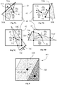
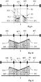
- the computation of the minimum depth by the fragment shader 1222 is illustrated on Figures 7A, 7B, 7C and 7D , representing a texel 40 having a center 41 and a texel area box 42 surrounding it, overlapped by respective triangles 51A, 51B, 51C and 51D.
- the center 41 together with its Cartesian coordinates in the depth map 20 is noted C (C x , C y ).
- the minimum depth is preferably derived from the depth p z and the partial depth derivatives dp z dx and dp z dy obtained and stored for texel 40 during shadow map generation, which enables to speed up the finding of that minimum depth.
- the minimum depth value for that texel 40 is given by the smallest of the minimum depths for all those triangles.
- the minimum depth is exploited for preliminary filtering: whenever a depth for a view sample is smaller than the stored minimum depth for a given depth map element, the corresponding pixel is classified as lit. Otherwise, the fragment shader 1222 is configured for carrying out the following operations.
- each texel 40 of part 4 of the depth map 20, corresponding to the selected triangle 51 having the smallest depth at the center 41 of texel 40, is exploited for shadow ray intersection tests.
- the depth d z for a considered view sample projected onto a point S (S x , S y ) inside texel 40 is compared with the depth d' z computed from the depth value p z and the partial depth derivatives dp z dx and dp z dy at the center 41 of texel 40.
- intersection test is given by the following algorithm:
- the use of the present disclosure is not limited to a live utilization but also extends to any other utilization, for example for processing known as postproduction processing in a recording studio for the display of synthesis images for example.
- the implementations described herein may be implemented in, for example, a method or a process, an apparatus, a software program, a data stream, or a signal. Even if only discussed in the context of a single form of implementation (for example, discussed only as a method or a device), the implementation of features discussed may also be implemented in other forms (for example a program).
- An apparatus may be implemented in, for example, appropriate hardware, software, and firmware.
- the methods may be implemented in, for example, an apparatus such as, for example, a processor, which refers to processing devices in general, including, for example, a computer, a microprocessor, an integrated circuit, or a programmable logic device.
- a processor may be characterized, therefore, as, for example, both a device configured to carry out a process and a device that includes a processor-readable medium (such as a storage device) having instructions for carrying out a process. Further, a processor-readable medium may store, in addition to or in lieu of instructions, data values produced by an implementation.
- implementations may produce a variety of signals formatted to carry information that may be, for example, stored or transmitted.
- the information may include, for example, instructions for performing a method, or data produced by one of the described implementations.
- a signal may be formatted to carry as data the rules for writing or reading the syntax of a described embodiment, or to carry as data the actual syntax-values written by a described embodiment.
- Such a signal may be formatted, for example, as an electromagnetic wave (for example, using a radio frequency portion of spectrum) or as a baseband signal.
- the formatting may include, for example, encoding a data stream and modulating a carrier with the encoded data stream.
- the information that the signal carries may be, for example, analog or digital information.
- the signal may be transmitted over a variety of different wired or wireless links, as is known.
- the signal may be stored on a processor-readable medium.
Landscapes
- Engineering & Computer Science (AREA)
- Physics & Mathematics (AREA)
- General Physics & Mathematics (AREA)
- Theoretical Computer Science (AREA)
- Computer Graphics (AREA)
- Image Generation (AREA)
- Computer Vision & Pattern Recognition (AREA)
Claims (15)
- Graphikverarbeitungsvorrichtung (1, 12), die dafür konfiguriert ist, auf der Grundlage mindestens einer Tiefenkarte (20), die eine Vielzahl von Elementen (40) umfasst, einen Schatten in einer dreidimensionalen Szene (2), die durch mindestens eine Lichtquelle (L) beleuchtet ist, zu berechnen, wobei die Tiefenkarte (20) mit einem zweidimensionalen begrenzten Raum verknüpft ist, der dafür ausgelegt ist, in Übereinstimmung mit einem Standpunkt (200) der Lichtquelle (L) ein Bild der Szene (2) zu rendern, wobei die Graphikverarbeitungsvorrichtung (1, 12) mindestens einen Prozessor umfasst, der konfiguriert ist zum:- Speichern von eine Tiefe (pz) repräsentierenden Informationen, die aus der Entfernung zwischen dem Standpunkt (200) und einer nächsten sichtbaren Oberfläche von dem Standpunkt bestehen, für jedes der Tiefenkartenelemente (40);- Speichern von Koordinaten von Scheiteln (V0x ... V2y) mindestens eines Oberflächenelements (510) der nächsten sichtbaren Oberfläche in jedem Element (40) mindestens eines Teils (4) der Tiefenkarte (20), wobei die Koordinaten in dem Raum der Tiefenkarte (20) ausgedrückt sind;- Speichern von Informationen, die eine lokale Tiefenänderung
 - Testen eines Strahlschnittpunkts in dem Teil (4) der Tiefenkarte (20) für mindestens ein Pixel des Bilds, wobei das mindestens eine Oberflächenelement (510) eine Tiefe (d'z) besitzt, die für das Pixel aus den Informationen, die die Tiefe repräsentieren, und aus der lokalen Tiefenänderung unter Berücksichtigung der Koordinaten der Scheitel berechnet wird;dadurch gekennzeichnet, dass der mindestens eine Prozessor ferner konfiguriert ist zum:- Berechnen mindestens einer minimalen Tiefe (81), die mit dem mindesten einen Oberflächenelement (510) verknüpft ist, für jedes Element (40, 401) des mindestens einen Teils (4) der Tiefenkarte (20), wobei die minimale Tiefe aus den Koordinaten der Scheitel und aus den Informationen, die die Tiefe repräsentieren, und aus der lokalen Tiefenänderung berechnet wird;- Vergleichen der Tiefe (dz), die mit mindestens einem Pixel des Bilds, das sich in dem Tiefenkartenelement (40, 401) befindet, verknüpft ist, mit der minimalen Tiefe, die mit dem Tiefenkartenelement und mit dem mindestens einem Oberflächenelement (510) verknüpft ist;- Klassifizieren des Pixels als beleuchtet, falls die mit dem Pixel verknüpfte Tiefe (dz) kleiner als die minimale Tiefe ist;- Klassifizieren des Pixels als abgeschattet, falls die mit dem Pixel verknüpfte Tiefe (dz) größer als die minimale Tiefe ist und falls für das Pixel aus den Strahlschnittpunkttests ein Strahlschnittpunkt mit dem mindestens einen Oberflächenelement (510) ermittelt wird.
 - Graphikverarbeitungsvorrichtung (1, 12) nach Anspruch 1, dadurch gekennzeichnet, dass der mindestens eine Prozessor ferner dafür konfiguriert ist, das Pixel als unbestimmt zu klassifizieren, falls das Pixel nicht als beleuchtet klassifiziert ist und nicht als abgeschattet klassifiziert ist, und einen Strahl (832, 842), der als Ursprung ein Szenefragment der dreidimensionalen Szene (2), das dem Pixel entspricht, besitzt, in Richtung des Standpunkts (200) zu verfolgen, um zu bestimmen, ob das Pixel beleuchtet ist.
- Graphikverarbeitungsvorrichtung (1, 12) nach Anspruch 2, dadurch gekennzeichnet, dass der mindestens eine Prozessor ferner dafür konfiguriert ist, den Strahl (832, 842) nur bis zu einer Entfernung zu dem Standpunkt (200) zu verfolgen, die der minimalen Tiefe (81) entspricht, die mit dem Tiefenkartenelement (402, 405), in dem sich das Pixel befindet, verknüpft ist.
- Graphikverarbeitungsvorrichtung (1, 12) nach einem der vorhergehenden Ansprüche, dadurch gekennzeichnet, dass das betrachtete Tiefenkartenelement (405), in dem sich das Pixel befindet, Nachbartiefenkartenelemente (406, 407) besitzt, die zu dem mindestens einen Teil (4) der Tiefenkarte (20) gehören, wobei der mindestens eine Prozessor ferner dafür konfiguriert ist, die minimale Tiefe für das betrachtete Tiefenkartenelement (405) ebenfalls aus den Koordinaten der Scheitel und aus den Informationen, die die Tiefe repräsentieren, und aus der lokalen Tiefenänderung, die in den Nachbartiefenkartenelementen (406, 407) für das mindestens eine Oberflächenelement, das mit den Nachbartiefenkartenelementen verknüpft ist, gespeichert ist, zu berechnen.
- Graphikverarbeitungsvorrichtung (1, 12) nach Anspruch 4, dadurch gekennzeichnet, dass der mindestens eine Prozessor ferner zu Folgendem konfiguriert ist, falls die mit dem Pixel verknüpfte Tiefe größer als die minimale Tiefe für das Tiefenkartenelement ist und falls das Pixel nicht als beleuchtet klassifiziert ist und nicht als abgeschattet klassifiziert ist:- zusätzliches Testen des Strahlschnittpunkts für das Pixel mit mindestens einem weiteren Oberflächenelement (514), das mit den Nachbartiefenkartenelementen (406, 407) verknüpft ist, die eine Tiefe besitzen, die in dem betrachteten Tiefenkartenelement aus den Informationen, die die Tiefe repräsentieren, und aus der lokalen Tiefenänderung, die in den Nachbartiefenkartenelementen gespeichert ist, unter Berücksichtigung der Koordinaten von Scheiteln, die in den Nachbartiefenkartenelementen gespeichert sind, berechnet wird;- Klassifizieren des Pixels als abgeschattet, falls für das Pixel aus den zusätzlichen Strahlschnittpunkttests ein Strahlschnittpunkt mit dem mindestens einen weiteren Oberflächenelement (514) ermittelt wird.
- Graphikverarbeitungsvorrichtung (1, 12) nach einem der Ansprüche 4 und 5, dadurch gekennzeichnet, dass für mindestens eines der betrachteten Tiefenkartenelemente (40) die Nachbartiefenkartenelemente aus acht Nachbartiefenkartenelementen bestehen, die das mindestens eine betrachtete Tiefenkartenelement umgeben.
- Graphikverarbeitungsvorrichtung (1, 12) nach einem der vorhergehenden Ansprüche, dadurch gekennzeichnet, dass jedes der Tiefenkartenelemente (40) eine Mitte (41) besitzt, wobei der mindestens eine Prozessor ferner konfiguriert ist zum:- Fortfahren mit einer vorläufigen Erweiterung des mindestens einen Oberflächenelements (510) auf mindestens ein jeweils erweitertes Oberflächenelement (520) bei der Bestimmung des mindestens einen Tiefenkartenelements (40), das mit dem Oberflächenelement verknüpft ist;- Bestimmen des mindestens einen erweiterten Oberflächenelements (520), das die Mitte (41) des Tiefenkartenelements bedeckt, für jedes mindestens eine Tiefenkartenelement (40);- Auswählen des erweiterten Oberflächenelements mit der kleinsten Tiefe in der Mitte unter dem mindestens einen erweiterten Oberflächenelement (520), das die Mitte des Tiefenkartenelements bedeckt;- Speichern der Koordinaten von Scheiteln und der Informationen, die die Tiefe repräsentieren, und der lokalen Tiefenänderung, die mit dem ausgewählten Oberflächenelement verknüpft ist, in dem Tiefenkartenelement, für das Tiefenkartenelement, das zu dem mindestens einen Teil (4) der Tiefenkarte (20) gehört.
- Graphikverarbeitungsvorrichtung (1, 12) nach einem der vorhergehenden Ansprüche, dadurch gekennzeichnet, dass der mindestens eine Prozessor ferner zum Berechnen der mindestens einen minimalen Tiefe bei mindestens einem Punkt des Tiefenkartenelements (40) und der Projektion in den Raum der Tiefenkarte für das mindestens eine Oberflächenelement (51), ein nächster Punkt genannt, konfiguriert ist, wobei der nächste Punkt mittels eines Gradienten (71) der Verringerung der Tiefenänderung in dem Raum der Tiefenkarte für das Oberflächenelement (51), der durch die Informationen, die die lokale Tiefenänderung
- Verfahren für die Graphikverarbeitung, das dafür ausgelegt ist, auf der Grundlage mindestens einer Tiefenkarte (20), die eine Vielzahl von Elementen (40) umfasst, einen Schatten in einer dreidimensionalen Szene (2), die durch mindestens eine Lichtquelle (L) beleuchtet ist, zu berechnen, wobei die Tiefenkarte (20) mit einem zweidimensionalen begrenzten Raum verknüpft ist, der dafür ausgelegt ist, in Übereinstimmung mit einem Standpunkt (200) der Lichtquelle (L) ein Bild der Szene (2) zu rendern, wobei das Graphikverarbeitungsverfahren umfasst:- Speichern von eine Tiefe repräsentierenden Informationen, die aus der Entfernung zwischen dem Standpunkt (200) und einer nächsten sichtbaren Oberfläche von dem Standpunkt bestehen, für jedes der Tiefenkartenelemente (40);- Speichern von Koordinaten von Scheiteln (V0x ... V2y) mindestens eines Oberflächenelements (510) der nächsten sichtbaren Oberfläche in jedem Element mindestens eines Teils (4) der Tiefenkarte (20), wobei die Koordinaten in dem Raum der Tiefenkarte (20) ausgedrückt sind;- Speichern von Informationen, die eine lokale Tiefenänderung
 - Testen eines Strahlschnittpunkts in dem Teil (4) der Tiefenkarte (20) für mindestens ein Pixel des Bilds, wobei das mindestens eine Oberflächenelement (510) eine Tiefe (d'z) besitzt, die für das Pixel aus den Informationen, die die Tiefe repräsentieren, und aus der lokalen Tiefenänderung unter Berücksichtigung der Koordinaten der Scheitel berechnet wird;dadurch gekennzeichnet, dass das Verfahren für die Graphikverarbeitung ferner enthält:- Berechnen mindestens einer minimalen Tiefe (81), die mit mindesten einem Oberflächenelement (510) verknüpft ist, für jedes Element (40, 401) des mindestens einen Teils (4) der Tiefenkarte (20), wobei die minimale Tiefe aus den Koordinaten der Scheitel und aus den Informationen, die die Tiefe repräsentieren, und aus der lokalen Tiefenänderung berechnet wird;- Vergleichen der Tiefe (dz), die mit mindestens einem Pixel des Bilds, das sich in dem Tiefenkartenelement (40, 401) befindet, verknüpft ist, mit der minimalen Tiefe, die mit dem Tiefenkartenelement und mit dem mindestens einem Oberflächenelement (510) verknüpft ist;- Klassifizieren des Pixels als beleuchtet, falls die mit dem Pixel verknüpfte Tiefe (dz) kleiner als die minimale Tiefe ist;- Klassifizieren des Pixels als abgeschattet, falls die mit dem Pixel verknüpfte Tiefe größer als die minimale Tiefe ist und falls für das Pixel aus den Strahlschnittpunkttests ein Strahlschnittpunkt mit dem mindestens einen Oberflächenelement (510) ermittelt wird.
 - Verfahren nach Anspruch 9, das ferner das Klassifizieren des Pixels als unbestimmt, falls das Pixel nicht als beleuchtet klassifiziert ist und nicht als abgeschattet klassifiziert ist, und das Verfolgen eines Strahls (832, 842), der als Ursprung ein Szenefragment der dreidimensionalen Szene (2), das dem Pixel entspricht, besitzt, in Richtung des Standpunkts (200), um zu bestimmen, ob das Pixel beleuchtet ist, umfasst.
- Verfahren nach Anspruch 10, wobei der Strahl (832, 842) nur bis zu einer Entfernung zu dem Standpunkt (200) verfolgt wird, die der minimalen Tiefe (81) entspricht, die mit dem Tiefenkartenelement (402, 405), in dem sich das Pixel befindet, verknüpft ist.
- Verfahren nach einem der Ansprüche 9 bis 11, wobei das betrachtete Tiefenkartenelement (405), in dem sich das Pixel befindet, Nachbartiefenkartenelemente (406, 407) besitzt, die zu dem mindestens einen Teil (4) der Tiefenkarte (20) gehören, wobei das Verfahren ferner das Berechnen der minimalen Tiefe für das betrachtete Tiefenkartenelement (405) ebenfalls aus den Koordinaten der Scheitel und aus den Informationen, die die Tiefe repräsentieren, und aus der lokalen Tiefenänderung, die in den Nachbartiefenkartenelementen (406, 407) für das mindestens eine Oberflächenelement, das mit den Nachbartiefenkartenelementen verknüpft ist, gespeichert ist, umfasst.
- Verfahren nach Anspruch 12, wobei das Verfahren ferner Folgendes umfasst, falls die mit dem Pixel verknüpfte Tiefe größer als die minimale Tiefe für das Tiefenkartenelement ist und falls das Pixel nicht als beleuchtet klassifiziert ist und nicht als abgeschattet klassifiziert ist:- zusätzliches Testen des Strahlschnittpunkts für das Pixel mit mindestens einem weiteren Oberflächenelement (514), das mit den Nachbartiefenkartenelementen (406, 407) verknüpft ist, die eine Tiefe besitzen, die in dem betrachteten Tiefenkartenelement aus den Informationen, die die Tiefe repräsentieren, und aus der lokalen Tiefenänderung, die in den Nachbartiefenkartenelementen gespeichert ist, unter Berücksichtigung der Koordinaten von Scheiteln, die in den Nachbartiefenkartenelementen gespeichert sind, berechnet wird;- Klassifizieren des Pixels als abgeschattet, falls für das Pixel aus den zusätzlichen Strahlschnittpunkttests ein Strahlschnittpunkt mit dem mindestens einen weiteren Oberflächenelement (514) ermittelt wird.
- Verfahren nach einem der Ansprüche 12 und 13, wobei für mindestens eines der betrachteten Tiefenkartenelemente (40) die Nachbartiefenkartenelemente aus acht Nachbartiefenkartenelementen bestehen, die das mindestens eine betrachtete Tiefenkartenelement umgeben.
- Computerprogramm für die Graphikverarbeitung, das Softwarecode umfasst, der dafür ausgelegt ist, in Übereinstimmung mit einem Verfahren nach einem der Ansprüche 9 bis 14 Schatten zu berechnen.
Priority Applications (2)
| Application Number | Priority Date | Filing Date | Title |
|---|---|---|---|
| EP14306804.7A EP3021286B1 (de) | 2014-11-13 | 2014-11-13 | Vorrichtung und Verfahren zur Berechnung von Schatten in einer 3D-Szene |
| US14/938,734 US10339703B2 (en) | 2014-11-13 | 2015-11-11 | Device and method to compute shadow in a 3D scene |
Applications Claiming Priority (1)
| Application Number | Priority Date | Filing Date | Title |
|---|---|---|---|
| EP14306804.7A EP3021286B1 (de) | 2014-11-13 | 2014-11-13 | Vorrichtung und Verfahren zur Berechnung von Schatten in einer 3D-Szene |
Publications (2)
| Publication Number | Publication Date |
|---|---|
| EP3021286A1 EP3021286A1 (de) | 2016-05-18 |
| EP3021286B1 true EP3021286B1 (de) | 2017-09-27 |
Family
ID=52016007
Family Applications (1)
| Application Number | Title | Priority Date | Filing Date |
|---|---|---|---|
| EP14306804.7A Active EP3021286B1 (de) | 2014-11-13 | 2014-11-13 | Vorrichtung und Verfahren zur Berechnung von Schatten in einer 3D-Szene |
Country Status (2)
| Country | Link |
|---|---|
| US (1) | US10339703B2 (de) |
| EP (1) | EP3021286B1 (de) |
Families Citing this family (17)
| Publication number | Priority date | Publication date | Assignee | Title |
|---|---|---|---|---|
| US10614614B2 (en) | 2015-09-29 | 2020-04-07 | Adshir Ltd. | Path tracing system employing distributed accelerating structures |
| US10565776B2 (en) | 2015-12-12 | 2020-02-18 | Adshir Ltd. | Method for fast generation of path traced reflections on a semi-reflective surface |
| US12008704B2 (en) | 2016-01-28 | 2024-06-11 | Snap Inc. | System for photo-realistic reflections in augmented reality |
| US10614612B2 (en) | 2018-06-09 | 2020-04-07 | Adshir Ltd. | Fast path traced reflections for augmented reality |
| GB2561557B (en) * | 2017-04-13 | 2020-08-12 | Advanced Risc Mach Ltd | Graphics processing method and apparatus in which modified edge positions are used in rasterisation |
| CN107958436B (zh) * | 2017-11-24 | 2021-05-07 | 中国航空工业集团公司西安航空计算技术研究所 | 一种面向OpenGL的图形负载量化检测方法 |
| US10699468B2 (en) | 2018-06-09 | 2020-06-30 | Adshir Ltd. | Method for non-planar specular reflections in hybrid ray tracing |
| US10922884B2 (en) * | 2019-07-18 | 2021-02-16 | Sony Corporation | Shape-refinement of triangular three-dimensional mesh using a modified shape from shading (SFS) scheme |
| KR102770795B1 (ko) * | 2019-09-09 | 2025-02-21 | 삼성전자주식회사 | 3d 렌더링 방법 및 장치 |
| US10970914B1 (en) | 2019-11-15 | 2021-04-06 | Imagination Technologies Limited | Multiple precision level intersection testing in a ray tracing system |
| US11164359B2 (en) * | 2019-12-27 | 2021-11-02 | Intel Corporation | Apparatus and method for using alpha values to improve ray tracing efficiency |
| US11017581B1 (en) | 2020-01-04 | 2021-05-25 | Adshir Ltd. | Method for constructing and traversing accelerating structures |
| CN111292405B (zh) * | 2020-02-06 | 2022-04-08 | 腾讯科技(深圳)有限公司 | 一种图像渲染的方法以及相关装置 |
| CN114036773B (zh) * | 2021-11-25 | 2023-06-30 | 河海大学 | 一种块体离散元数值模型外轮廓几何快速检索方法 |
| CN114419241A (zh) * | 2022-01-18 | 2022-04-29 | 北京世纪高通科技有限公司 | 一种三维模型构建方法、装置及存储介质 |
| WO2022126145A1 (en) * | 2022-02-01 | 2022-06-16 | Innopeak Technology, Inc. | Hybrid shadow rendering |
| JP7557490B2 (ja) * | 2022-03-02 | 2024-09-27 | 任天堂株式会社 | 情報処理プログラム、情報処理システム、情報処理装置、および、情報処理方法 |
Family Cites Families (5)
| Publication number | Priority date | Publication date | Assignee | Title |
|---|---|---|---|---|
| JPH0778267A (ja) | 1993-07-09 | 1995-03-20 | Silicon Graphics Inc | 陰影を表示する方法及びコンピュータ制御表示システム |
| US6690372B2 (en) | 2000-05-31 | 2004-02-10 | Nvidia Corporation | System, method and article of manufacture for shadow mapping |
| KR101585998B1 (ko) | 2009-11-10 | 2016-01-15 | 삼성전자주식회사 | 영상 처리 장치 및 방법 |
| EP2956911A1 (de) | 2013-02-12 | 2015-12-23 | Thomson Licensing | Verfahren und vorrichtung zur feststellung der grenze zwischen objekten einer szene in einer tiefenkarte |
| JP2016510473A (ja) | 2013-02-12 | 2016-04-07 | トムソン ライセンシングThomson Licensing | デプスマップのコンテンツを強化するための方法およびデバイス |
-
2014
- 2014-11-13 EP EP14306804.7A patent/EP3021286B1/de active Active
-
2015
- 2015-11-11 US US14/938,734 patent/US10339703B2/en active Active
Non-Patent Citations (1)
| Title |
|---|
| None * |
Also Published As
| Publication number | Publication date |
|---|---|
| US10339703B2 (en) | 2019-07-02 |
| EP3021286A1 (de) | 2016-05-18 |
| US20190057544A1 (en) | 2019-02-21 |
Similar Documents
| Publication | Publication Date | Title |
|---|---|---|
| EP3021286B1 (de) | Vorrichtung und Verfahren zur Berechnung von Schatten in einer 3D-Szene | |
| US9330475B2 (en) | Color buffer and depth buffer compression | |
| US9569811B2 (en) | Rendering graphics to overlapping bins | |
| US10510179B2 (en) | Method and device for enriching the content of a depth map | |
| US8194071B2 (en) | Tile based graphics rendering | |
| US10089774B2 (en) | Tessellation in tile-based rendering | |
| KR102122454B1 (ko) | 이전 타일의 이미지를 이용하여 현재 프레임을 렌더링하는 방법 및 장치 | |
| US9558586B2 (en) | Method for estimating the opacity level in a scene and corresponding device | |
| US10074211B2 (en) | Method and device for establishing the frontier between objects of a scene in a depth map | |
| EP3427229B1 (de) | Änderung von visibilitätsinformationen | |
| US9747720B2 (en) | Method and device for processing a geometry image of a 3D scene | |
| KR20180023856A (ko) | 그래픽 처리 시스템 및 그래픽 프로세서 | |
| US9607435B2 (en) | Method for rendering an image synthesis and corresponding device | |
| US20140333611A1 (en) | Method and device for visualizing contact(s) between objects of a virtual scene | |
| CN106447593B (zh) | 操作图形处理流水线的方法、图形处理流水线、存储介质 |
Legal Events
| Date | Code | Title | Description |
|---|---|---|---|
| PUAI | Public reference made under article 153(3) epc to a published international application that has entered the european phase |
Free format text: ORIGINAL CODE: 0009012 |
|
| AK | Designated contracting states |
Kind code of ref document: A1 Designated state(s): AL AT BE BG CH CY CZ DE DK EE ES FI FR GB GR HR HU IE IS IT LI LT LU LV MC MK MT NL NO PL PT RO RS SE SI SK SM TR |
|
| AX | Request for extension of the european patent |
Extension state: BA ME |
|
| 17P | Request for examination filed |
Effective date: 20161115 |
|
| RBV | Designated contracting states (corrected) |
Designated state(s): AL AT BE BG CH CY CZ DE DK EE ES FI FR GB GR HR HU IE IS IT LI LT LU LV MC MK MT NL NO PL PT RO RS SE SI SK SM TR |
|
| RIC1 | Information provided on ipc code assigned before grant |
Ipc: G06T 15/06 20110101AFI20161213BHEP Ipc: G06T 15/60 20060101ALI20161213BHEP |
|
| GRAP | Despatch of communication of intention to grant a patent |
Free format text: ORIGINAL CODE: EPIDOSNIGR1 |
|
| INTG | Intention to grant announced |
Effective date: 20170126 |
|
| GRAJ | Information related to disapproval of communication of intention to grant by the applicant or resumption of examination proceedings by the epo deleted |
Free format text: ORIGINAL CODE: EPIDOSDIGR1 |
|
| GRAP | Despatch of communication of intention to grant a patent |
Free format text: ORIGINAL CODE: EPIDOSNIGR1 |
|
| INTC | Intention to grant announced (deleted) | ||
| INTG | Intention to grant announced |
Effective date: 20170418 |
|
| GRAS | Grant fee paid |
Free format text: ORIGINAL CODE: EPIDOSNIGR3 |
|
| GRAA | (expected) grant |
Free format text: ORIGINAL CODE: 0009210 |
|
| AK | Designated contracting states |
Kind code of ref document: B1 Designated state(s): AL AT BE BG CH CY CZ DE DK EE ES FI FR GB GR HR HU IE IS IT LI LT LU LV MC MK MT NL NO PL PT RO RS SE SI SK SM TR |
|
| REG | Reference to a national code |
Ref country code: GB Ref legal event code: FG4D |
|
| REG | Reference to a national code |
Ref country code: CH Ref legal event code: EP |
|
| REG | Reference to a national code |
Ref country code: AT Ref legal event code: REF Ref document number: 932650 Country of ref document: AT Kind code of ref document: T Effective date: 20171015 |
|
| REG | Reference to a national code |
Ref country code: IE Ref legal event code: FG4D |
|
| REG | Reference to a national code |
Ref country code: DE Ref legal event code: R084 Ref document number: 602014015036 Country of ref document: DE |
|
| REG | Reference to a national code |
Ref country code: DE Ref legal event code: R096 Ref document number: 602014015036 Country of ref document: DE |
|
| REG | Reference to a national code |
Ref country code: FR Ref legal event code: PLFP Year of fee payment: 4 |
|
| PG25 | Lapsed in a contracting state [announced via postgrant information from national office to epo] |
Ref country code: SE Free format text: LAPSE BECAUSE OF FAILURE TO SUBMIT A TRANSLATION OF THE DESCRIPTION OR TO PAY THE FEE WITHIN THE PRESCRIBED TIME-LIMIT Effective date: 20170927 Ref country code: LT Free format text: LAPSE BECAUSE OF FAILURE TO SUBMIT A TRANSLATION OF THE DESCRIPTION OR TO PAY THE FEE WITHIN THE PRESCRIBED TIME-LIMIT Effective date: 20170927 Ref country code: HR Free format text: LAPSE BECAUSE OF FAILURE TO SUBMIT A TRANSLATION OF THE DESCRIPTION OR TO PAY THE FEE WITHIN THE PRESCRIBED TIME-LIMIT Effective date: 20170927 Ref country code: NO Free format text: LAPSE BECAUSE OF FAILURE TO SUBMIT A TRANSLATION OF THE DESCRIPTION OR TO PAY THE FEE WITHIN THE PRESCRIBED TIME-LIMIT Effective date: 20171227 Ref country code: FI Free format text: LAPSE BECAUSE OF FAILURE TO SUBMIT A TRANSLATION OF THE DESCRIPTION OR TO PAY THE FEE WITHIN THE PRESCRIBED TIME-LIMIT Effective date: 20170927 |
|
| REG | Reference to a national code |
Ref country code: NL Ref legal event code: MP Effective date: 20170927 |
|
| REG | Reference to a national code |
Ref country code: LT Ref legal event code: MG4D |
|
| REG | Reference to a national code |
Ref country code: AT Ref legal event code: MK05 Ref document number: 932650 Country of ref document: AT Kind code of ref document: T Effective date: 20170927 |
|
| PG25 | Lapsed in a contracting state [announced via postgrant information from national office to epo] |
Ref country code: LV Free format text: LAPSE BECAUSE OF FAILURE TO SUBMIT A TRANSLATION OF THE DESCRIPTION OR TO PAY THE FEE WITHIN THE PRESCRIBED TIME-LIMIT Effective date: 20170927 Ref country code: BG Free format text: LAPSE BECAUSE OF FAILURE TO SUBMIT A TRANSLATION OF THE DESCRIPTION OR TO PAY THE FEE WITHIN THE PRESCRIBED TIME-LIMIT Effective date: 20171227 Ref country code: GR Free format text: LAPSE BECAUSE OF FAILURE TO SUBMIT A TRANSLATION OF THE DESCRIPTION OR TO PAY THE FEE WITHIN THE PRESCRIBED TIME-LIMIT Effective date: 20171228 Ref country code: RS Free format text: LAPSE BECAUSE OF FAILURE TO SUBMIT A TRANSLATION OF THE DESCRIPTION OR TO PAY THE FEE WITHIN THE PRESCRIBED TIME-LIMIT Effective date: 20170927 |
|
| PG25 | Lapsed in a contracting state [announced via postgrant information from national office to epo] |
Ref country code: NL Free format text: LAPSE BECAUSE OF FAILURE TO SUBMIT A TRANSLATION OF THE DESCRIPTION OR TO PAY THE FEE WITHIN THE PRESCRIBED TIME-LIMIT Effective date: 20170927 |
|
| PG25 | Lapsed in a contracting state [announced via postgrant information from national office to epo] |
Ref country code: RO Free format text: LAPSE BECAUSE OF FAILURE TO SUBMIT A TRANSLATION OF THE DESCRIPTION OR TO PAY THE FEE WITHIN THE PRESCRIBED TIME-LIMIT Effective date: 20170927 Ref country code: ES Free format text: LAPSE BECAUSE OF FAILURE TO SUBMIT A TRANSLATION OF THE DESCRIPTION OR TO PAY THE FEE WITHIN THE PRESCRIBED TIME-LIMIT Effective date: 20170927 Ref country code: CZ Free format text: LAPSE BECAUSE OF FAILURE TO SUBMIT A TRANSLATION OF THE DESCRIPTION OR TO PAY THE FEE WITHIN THE PRESCRIBED TIME-LIMIT Effective date: 20170927 |
|
| PG25 | Lapsed in a contracting state [announced via postgrant information from national office to epo] |
Ref country code: SK Free format text: LAPSE BECAUSE OF FAILURE TO SUBMIT A TRANSLATION OF THE DESCRIPTION OR TO PAY THE FEE WITHIN THE PRESCRIBED TIME-LIMIT Effective date: 20170927 Ref country code: EE Free format text: LAPSE BECAUSE OF FAILURE TO SUBMIT A TRANSLATION OF THE DESCRIPTION OR TO PAY THE FEE WITHIN THE PRESCRIBED TIME-LIMIT Effective date: 20170927 Ref country code: IT Free format text: LAPSE BECAUSE OF FAILURE TO SUBMIT A TRANSLATION OF THE DESCRIPTION OR TO PAY THE FEE WITHIN THE PRESCRIBED TIME-LIMIT Effective date: 20170927 Ref country code: SM Free format text: LAPSE BECAUSE OF FAILURE TO SUBMIT A TRANSLATION OF THE DESCRIPTION OR TO PAY THE FEE WITHIN THE PRESCRIBED TIME-LIMIT Effective date: 20170927 Ref country code: IS Free format text: LAPSE BECAUSE OF FAILURE TO SUBMIT A TRANSLATION OF THE DESCRIPTION OR TO PAY THE FEE WITHIN THE PRESCRIBED TIME-LIMIT Effective date: 20180127 Ref country code: AT Free format text: LAPSE BECAUSE OF FAILURE TO SUBMIT A TRANSLATION OF THE DESCRIPTION OR TO PAY THE FEE WITHIN THE PRESCRIBED TIME-LIMIT Effective date: 20170927 |
|
| REG | Reference to a national code |
Ref country code: DE Ref legal event code: R097 Ref document number: 602014015036 Country of ref document: DE |
|
| PG25 | Lapsed in a contracting state [announced via postgrant information from national office to epo] |
Ref country code: MC Free format text: LAPSE BECAUSE OF FAILURE TO SUBMIT A TRANSLATION OF THE DESCRIPTION OR TO PAY THE FEE WITHIN THE PRESCRIBED TIME-LIMIT Effective date: 20170927 |
|
| PG25 | Lapsed in a contracting state [announced via postgrant information from national office to epo] |
Ref country code: DK Free format text: LAPSE BECAUSE OF FAILURE TO SUBMIT A TRANSLATION OF THE DESCRIPTION OR TO PAY THE FEE WITHIN THE PRESCRIBED TIME-LIMIT Effective date: 20170927 Ref country code: CH Free format text: LAPSE BECAUSE OF NON-PAYMENT OF DUE FEES Effective date: 20171130 Ref country code: LI Free format text: LAPSE BECAUSE OF NON-PAYMENT OF DUE FEES Effective date: 20171130 |
|
| PLBE | No opposition filed within time limit |
Free format text: ORIGINAL CODE: 0009261 |
|
| STAA | Information on the status of an ep patent application or granted ep patent |
Free format text: STATUS: NO OPPOSITION FILED WITHIN TIME LIMIT |
|
| PG25 | Lapsed in a contracting state [announced via postgrant information from national office to epo] |
Ref country code: LU Free format text: LAPSE BECAUSE OF NON-PAYMENT OF DUE FEES Effective date: 20171113 Ref country code: PL Free format text: LAPSE BECAUSE OF FAILURE TO SUBMIT A TRANSLATION OF THE DESCRIPTION OR TO PAY THE FEE WITHIN THE PRESCRIBED TIME-LIMIT Effective date: 20170927 |
|
| REG | Reference to a national code |
Ref country code: BE Ref legal event code: MM Effective date: 20171130 |
|
| 26N | No opposition filed |
Effective date: 20180628 |
|
| REG | Reference to a national code |
Ref country code: IE Ref legal event code: MM4A |
|
| PG25 | Lapsed in a contracting state [announced via postgrant information from national office to epo] |
Ref country code: MT Free format text: LAPSE BECAUSE OF NON-PAYMENT OF DUE FEES Effective date: 20171113 |
|
| PG25 | Lapsed in a contracting state [announced via postgrant information from national office to epo] |
Ref country code: IE Free format text: LAPSE BECAUSE OF NON-PAYMENT OF DUE FEES Effective date: 20171113 |
|
| PG25 | Lapsed in a contracting state [announced via postgrant information from national office to epo] |
Ref country code: SI Free format text: LAPSE BECAUSE OF FAILURE TO SUBMIT A TRANSLATION OF THE DESCRIPTION OR TO PAY THE FEE WITHIN THE PRESCRIBED TIME-LIMIT Effective date: 20170927 Ref country code: BE Free format text: LAPSE BECAUSE OF NON-PAYMENT OF DUE FEES Effective date: 20171130 |
|
| PG25 | Lapsed in a contracting state [announced via postgrant information from national office to epo] |
Ref country code: HU Free format text: LAPSE BECAUSE OF FAILURE TO SUBMIT A TRANSLATION OF THE DESCRIPTION OR TO PAY THE FEE WITHIN THE PRESCRIBED TIME-LIMIT; INVALID AB INITIO Effective date: 20141113 |
|
| GBPC | Gb: european patent ceased through non-payment of renewal fee |
Effective date: 20181113 |
|
| PG25 | Lapsed in a contracting state [announced via postgrant information from national office to epo] |
Ref country code: CY Free format text: LAPSE BECAUSE OF FAILURE TO SUBMIT A TRANSLATION OF THE DESCRIPTION OR TO PAY THE FEE WITHIN THE PRESCRIBED TIME-LIMIT Effective date: 20170927 |
|
| PG25 | Lapsed in a contracting state [announced via postgrant information from national office to epo] |
Ref country code: MK Free format text: LAPSE BECAUSE OF FAILURE TO SUBMIT A TRANSLATION OF THE DESCRIPTION OR TO PAY THE FEE WITHIN THE PRESCRIBED TIME-LIMIT Effective date: 20170927 |
|
| PG25 | Lapsed in a contracting state [announced via postgrant information from national office to epo] |
Ref country code: GB Free format text: LAPSE BECAUSE OF NON-PAYMENT OF DUE FEES Effective date: 20181113 |
|
| PG25 | Lapsed in a contracting state [announced via postgrant information from national office to epo] |
Ref country code: TR Free format text: LAPSE BECAUSE OF FAILURE TO SUBMIT A TRANSLATION OF THE DESCRIPTION OR TO PAY THE FEE WITHIN THE PRESCRIBED TIME-LIMIT Effective date: 20170927 |
|
| PG25 | Lapsed in a contracting state [announced via postgrant information from national office to epo] |
Ref country code: PT Free format text: LAPSE BECAUSE OF FAILURE TO SUBMIT A TRANSLATION OF THE DESCRIPTION OR TO PAY THE FEE WITHIN THE PRESCRIBED TIME-LIMIT Effective date: 20170927 |
|
| PG25 | Lapsed in a contracting state [announced via postgrant information from national office to epo] |
Ref country code: AL Free format text: LAPSE BECAUSE OF FAILURE TO SUBMIT A TRANSLATION OF THE DESCRIPTION OR TO PAY THE FEE WITHIN THE PRESCRIBED TIME-LIMIT Effective date: 20170927 |
|
| P01 | Opt-out of the competence of the unified patent court (upc) registered |
Effective date: 20230527 |
|
| PGFP | Annual fee paid to national office [announced via postgrant information from national office to epo] |
Ref country code: DE Payment date: 20251117 Year of fee payment: 12 |
|
| PGFP | Annual fee paid to national office [announced via postgrant information from national office to epo] |
Ref country code: FR Payment date: 20251127 Year of fee payment: 12 |