EP2956786B1 - Messverfahren und -vorrichtung für magnetresonanzanwendungen - Google Patents
Messverfahren und -vorrichtung für magnetresonanzanwendungen Download PDFInfo
- Publication number
- EP2956786B1 EP2956786B1 EP14709993.1A EP14709993A EP2956786B1 EP 2956786 B1 EP2956786 B1 EP 2956786B1 EP 14709993 A EP14709993 A EP 14709993A EP 2956786 B1 EP2956786 B1 EP 2956786B1
- Authority
- EP
- European Patent Office
- Prior art keywords
- measuring
- measurement
- radiofrequency
- magnetic field
- sensor
- Prior art date
- Legal status (The legal status is an assumption and is not a legal conclusion. Google has not performed a legal analysis and makes no representation as to the accuracy of the status listed.)
- Active
Links
Images


Classifications
-
- G—PHYSICS
- G01—MEASURING; TESTING
- G01R—MEASURING ELECTRIC VARIABLES; MEASURING MAGNETIC VARIABLES
- G01R33/00—Arrangements or instruments for measuring magnetic variables
- G01R33/20—Arrangements or instruments for measuring magnetic variables involving magnetic resonance
- G01R33/24—Arrangements or instruments for measuring magnetic variables involving magnetic resonance for measuring direction or magnitude of magnetic fields or magnetic flux
- G01R33/243—Spatial mapping of the polarizing magnetic field
-
- G—PHYSICS
- G01—MEASURING; TESTING
- G01R—MEASURING ELECTRIC VARIABLES; MEASURING MAGNETIC VARIABLES
- G01R33/00—Arrangements or instruments for measuring magnetic variables
- G01R33/20—Arrangements or instruments for measuring magnetic variables involving magnetic resonance
- G01R33/24—Arrangements or instruments for measuring magnetic variables involving magnetic resonance for measuring direction or magnitude of magnetic fields or magnetic flux
-
- G—PHYSICS
- G01—MEASURING; TESTING
- G01R—MEASURING ELECTRIC VARIABLES; MEASURING MAGNETIC VARIABLES
- G01R33/00—Arrangements or instruments for measuring magnetic variables
- G01R33/20—Arrangements or instruments for measuring magnetic variables involving magnetic resonance
- G01R33/28—Details of apparatus provided for in groups G01R33/44 - G01R33/64
- G01R33/288—Provisions within MR facilities for enhancing safety during MR, e.g. reduction of the specific absorption rate [SAR], detection of ferromagnetic objects in the scanner room
-
- G—PHYSICS
- G01—MEASURING; TESTING
- G01R—MEASURING ELECTRIC VARIABLES; MEASURING MAGNETIC VARIABLES
- G01R33/00—Arrangements or instruments for measuring magnetic variables
- G01R33/20—Arrangements or instruments for measuring magnetic variables involving magnetic resonance
- G01R33/28—Details of apparatus provided for in groups G01R33/44 - G01R33/64
- G01R33/32—Excitation or detection systems, e.g. using radio frequency signals
- G01R33/34—Constructional details, e.g. resonators, specially adapted to MR
-
- G—PHYSICS
- G01—MEASURING; TESTING
- G01R—MEASURING ELECTRIC VARIABLES; MEASURING MAGNETIC VARIABLES
- G01R33/00—Arrangements or instruments for measuring magnetic variables
- G01R33/20—Arrangements or instruments for measuring magnetic variables involving magnetic resonance
- G01R33/28—Details of apparatus provided for in groups G01R33/44 - G01R33/64
- G01R33/38—Systems for generation, homogenisation or stabilisation of the main or gradient magnetic field
- G01R33/385—Systems for generation, homogenisation or stabilisation of the main or gradient magnetic field using gradient magnetic field coils
-
- G—PHYSICS
- G01—MEASURING; TESTING
- G01R—MEASURING ELECTRIC VARIABLES; MEASURING MAGNETIC VARIABLES
- G01R33/00—Arrangements or instruments for measuring magnetic variables
- G01R33/20—Arrangements or instruments for measuring magnetic variables involving magnetic resonance
- G01R33/44—Arrangements or instruments for measuring magnetic variables involving magnetic resonance using nuclear magnetic resonance [NMR]
- G01R33/48—NMR imaging systems
- G01R33/54—Signal processing systems, e.g. using pulse sequences ; Generation or control of pulse sequences; Operator console
-
- G—PHYSICS
- G01—MEASURING; TESTING
- G01R—MEASURING ELECTRIC VARIABLES; MEASURING MAGNETIC VARIABLES
- G01R33/00—Arrangements or instruments for measuring magnetic variables
- G01R33/20—Arrangements or instruments for measuring magnetic variables involving magnetic resonance
- G01R33/44—Arrangements or instruments for measuring magnetic variables involving magnetic resonance using nuclear magnetic resonance [NMR]
- G01R33/48—NMR imaging systems
- G01R33/54—Signal processing systems, e.g. using pulse sequences ; Generation or control of pulse sequences; Operator console
- G01R33/56—Image enhancement or correction, e.g. subtraction or averaging techniques, e.g. improvement of signal-to-noise ratio and resolution
- G01R33/565—Correction of image distortions, e.g. due to magnetic field inhomogeneities
- G01R33/56572—Correction of image distortions, e.g. due to magnetic field inhomogeneities caused by a distortion of a gradient magnetic field, e.g. non-linearity of a gradient magnetic field
-
- G—PHYSICS
- G01—MEASURING; TESTING
- G01R—MEASURING ELECTRIC VARIABLES; MEASURING MAGNETIC VARIABLES
- G01R33/00—Arrangements or instruments for measuring magnetic variables
- G01R33/20—Arrangements or instruments for measuring magnetic variables involving magnetic resonance
- G01R33/44—Arrangements or instruments for measuring magnetic variables involving magnetic resonance using nuclear magnetic resonance [NMR]
- G01R33/48—NMR imaging systems
- G01R33/54—Signal processing systems, e.g. using pulse sequences ; Generation or control of pulse sequences; Operator console
- G01R33/56—Image enhancement or correction, e.g. subtraction or averaging techniques, e.g. improvement of signal-to-noise ratio and resolution
- G01R33/565—Correction of image distortions, e.g. due to magnetic field inhomogeneities
- G01R33/5659—Correction of image distortions, e.g. due to magnetic field inhomogeneities caused by a distortion of the RF magnetic field, e.g. spatial inhomogeneities of the RF magnetic field
-
- G—PHYSICS
- G01—MEASURING; TESTING
- G01R—MEASURING ELECTRIC VARIABLES; MEASURING MAGNETIC VARIABLES
- G01R33/00—Arrangements or instruments for measuring magnetic variables
- G01R33/20—Arrangements or instruments for measuring magnetic variables involving magnetic resonance
- G01R33/44—Arrangements or instruments for measuring magnetic variables involving magnetic resonance using nuclear magnetic resonance [NMR]
- G01R33/48—NMR imaging systems
- G01R33/54—Signal processing systems, e.g. using pulse sequences ; Generation or control of pulse sequences; Operator console
- G01R33/56—Image enhancement or correction, e.g. subtraction or averaging techniques, e.g. improvement of signal-to-noise ratio and resolution
- G01R33/565—Correction of image distortions, e.g. due to magnetic field inhomogeneities
- G01R33/56518—Correction of image distortions, e.g. due to magnetic field inhomogeneities due to eddy currents, e.g. caused by switching of the gradient magnetic field
Definitions
- the present invention relates to the technical field of magnetic resonance and in particular NMR (Nuclear Magnetic Resonance, MRI (Magnetic Resonance Imaging) and / or SRM (Magnetic Resonance Spectroscopy) devices.
- NMR Nuclear Magnetic Resonance
- MRI Magnetic Resonance Imaging
- SRM Magnetic Resonance Spectroscopy
- the present invention relates more particularly to the field of instruments or devices adapted to measure radiofrequency electromagnetic fields and magnetic field gradients as well as the static magnetic field applied to an object to be studied by magnetic resonance.
- NMR, MRI and / or SRM apparatuses are complex instruments that employ radiofrequency magnetic fields and magnetic field gradients to create images and / or spectra of a region of the object or body to study. These fields are created and organized at the rhythm of temporal sequences whose theoretical chronogram is described in the literature for generic families of sequences.
- one of the methods used is to connect measuring instruments (oscilloscope) in the technical room to different radio frequency amplifiers and gradients on takeovers provided for this purpose.
- measuring instruments oscilloscope
- the gains of the various elements must be provided by the manufacturer of the device.
- the measurement of currents does not correspond to the exact image of the fields created by these currents in the magnet.
- the present invention therefore aims to remedy the disadvantages of the prior art by proposing a measuring device for magnetic resonance applications, adapted to measure in a simple and reliable way, the radiofrequency electromagnetic fields and the magnetic field gradients actually applied to a object to be examined by magnetic resonance.
- claim 1 defines a measuring device for magnetic resonance applications, comprising three measurement axes corresponding to the axis of a main magnetic field and to the two transverse axes of a closed or semi-closed space. in which radiofrequency electromagnetic fields and magnetic field gradients are created.
- Another object of the invention is to provide a simple and reliable method for measuring radiofrequency electromagnetic fields and magnetic field gradients actually applied to an object to be examined by magnetic resonance.
- the object of the invention relates to a measuring device 1 for a magnetic resonance apparatus 2, of all types known per se, such as NMR, MRI or SRM.
- the magnetic resonance apparatus 2 comprises a magnet system 3 adapted to generate a static main magnetic field B 0 inside a space 4 in which is positioned an object 5 to be examined, such as a body human or animal.
- the magnetic resonance apparatus 2 also has gradient coils 6 fed by a power supply 7 to generate three further magnetic fields having a gradient in the x, y, z directions defining a perpendicular coordinate system. Thus, within space 5, magnetic field gradients are created along the x, y and z axes.
- the magnetic resonance apparatus 2 also comprises one or more radiofrequency transmitter coils 9 for generating magnetic excitation RF pulses.
- This radiofrequency transmitter coil 9 is conventionally connected to a transmission circuit and to a control unit 10.
- This magnetic resonance apparatus 2 has an architecture such that the space 4 is in the form of a closed space such as a tunnel, the longitudinal axis z of which the object 5 is placed, corresponds to the axis of the main magnetic field, either in the form of a semi-open space with transverse access in which the z- axis of the main magnetic field is perpendicular to the object 5.
- the transmitting radio frequency magnetic field B 1 is perpendicular to the axis of the main magnetic field B 0 and can thus be established according to one or the other or both transverse axes x or y .
- the magnetic resonance apparatus 2 is not described in more detail because it is well known to those skilled in the art and is not part of the subject of the invention.
- the main axis of the object 5 to be examined is parallel to the axis of the main static magnetic field B 0 .
- This arrangement conditions the geometry of the coils of gradient 6 , transmitting and receiving coils 9 but also the geometry of the sensors in accordance with the invention described hereinafter.
- the geometries are different as well as for the sensors according to the invention.
- one skilled in the art is able to transpose the description of the invention to adapt to other configurations of magnetic resonance devices.
- the measuring device 1 comprises a measurement box 12 intended to be placed inside the space 4 in which the object of study 5 is positioned.
- This measurement box 12 is connected via a transmission beam 13 to a signal control and processing unit 14 located outside the space 4.
- the measuring box 12 is adapted to measure an image of the electromagnetic fields generated inside the space 4.
- the measuring case 12 comprises as illustrated in FIGS. Fig. 2 and 3 A sensor 15 for measuring radio frequency magnetic fields B 1 comprising a radio frequency coil assembly 16, 17 for measuring magnetic components of the RF magnetic fields in the two transverse axes x, y that is to say in the plane x, y orthogonal to the z axis of the magnetic field B 0 .
- a surface S of the order of cm 2 makes it possible to collect tens of mV at some V of signal radio frequency.
- the sensor may have several turns.
- the radiofrequency magnetic fields B 1 created are often in quadrature so that two coil assemblies 16, 17 therefore make it possible to collect the two components of the emission field.
- the quadrature measurement can be done using a butterfly loop 16.
- the measuring sensor 15 can comprise a butterfly-shaped double planar coil 16 and a plane coil 17 extending parallel to the double coil, being centered with respect thereto.
- the double butterfly-shaped plane coil 16 has a first loop with a first connection terminal 16 1 located at one end of this first loop and a second loop placed next to and connected to the first loop, presenting a second terminal. connection 16 2 at the end of this second loop.
- the plane coil 17 is in the form of a loop provided at its two ends placed side by side, two connection terminals 17 1 , 17 2 .
- the ratio of the surfaces of a single coil and a butterfly spool depends on the volume probed for the measurement of the radio frequency magnetic field B 1 .
- the single coil 17 and the butterfly coil 16 are superimposed and perfectly centered (on a double-sided circuit for example) to avoid any crosstalk between the two measurements. It may be envisaged to make the coils 16 , 17 by three turns of rectangular shape of the order each of 1 cm side.
- the measurement box 12 also comprises a measurement sensor 20 of the magnetic field gradients.
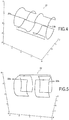
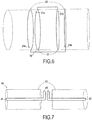
- This measurement sensor 20 comprises, as illustrated more particularly by the Fig . 2 , 4 , 5 and 6 , three sets of coils 21, 22, 23 for measuring the magnetic field gradients respectively along the three measurement axes x, y, z.
- three sets of coils 21, 22, 23 are made to cover the three axes x, y, z.
- the relatively low frequency of the magnetic field gradients makes it necessary to multiply the turns of the measuring coils in order to recover enough voltage.
- the principle of reciprocity emission-reception is exploited.
- the magnetic field gradients necessary for the spatial location of the signal in MRI or for the measurement of NMR scattering coefficients are created by windings of known geometries. To measure these field gradients, the three sets of coils are similar in reduction to gradient coils 6 .
- the measurement sensor 20 intrinsically measures a magnetic field gradient, so that its position in space is arbitrary as long as it is placed in a region in which the field gradient is created and its orientation is correct.
- the three sets of coils 21, 22 , 23 are mounted to fit into a mounting cylinder 25.
- the assembly of the planar radiofrequency coils of the measurement sensor 15 of the radio frequency magnetic fields is positioned inside the cylinder mounting 25.
- the measurement housing 12 comprises a sensor 30 for measuring the main magnetic field B 0 and its variations.
- This sensor 30 thus comprises two coils of Helmholtz type 31 ( Fig. 2 and 6 ) to measure the variations of the main magnetic field B 0 and a Hall effect cell 32 to evaluate the field main magnet B 0 in amplitude and direction.
- the two coils Helmholtz type 31 are connected in series and have connection terminals 31a, 31b.
- the two coils 31 for measuring the variations of the main magnetic field also register in the mounting cylinder 25.
- the Hall effect cell 32 is mounted inside the mounting cylinder 25 and its orientation is defined precisely with respect to those of the sensors 15, 20, 30 and 40.
- the Hall effect cell 32 thus makes it possible to measure the amplitude of the main magnetic field B 0 and thus to deduce from it the operating frequency of the apparatus to adapt the amplification of the signals from the measurement sensors 15 and 40 in relation to their transfer functions. Moreover, the knowledge of the two angles (azimuth and elevation) of all the measurement sensors with respect to the axis of the main magnetic field B 0 of the apparatus makes it possible to correct by a simple trigonometric calculation the values measured by these sensors to replace them in the reference of the main magnetic field B 0 or to change the alignment of the entire measuring system to align with the main magnetic field B 0 .
- the measurement box 12 also comprises a measurement sensor 40 of the radiofrequency electric field.
- This sensor 40 measures the electric fields generated in the space 4 by the radiofrequency magnetic field created to switch the nuclear magnetization.
- this measurement sensor 40 comprises two independent electrical conductor wires 41 , 42 mounted in alignment, each surrounded by a material with a high relative dielectric permittivity 43.
- the material surrounding the conductive wires 41 , 42 has a relative dielectric permittivity> 50.
- the simplest is water whose relative permittivity is of the order of 80 at the frequencies considered. Water in liquid form is difficult to use for obvious practical reasons. It is proposed to gel this water with agar agar.
- the solution of water and agar agar (a few percent) as well as a small amount of preservative (NaN3 for example) is brought to a temperature of 80 ° C, the cooling at room temperature provides a solid gel in which are inserted the electrical conductors 41, 42 such as copper strands.
- the measurement sensor 40 is mounted in the housing so that the electrical conductor wires 41, 42 of the radio frequency electric field measuring sensor extend parallel to the axis of the mounting cylinder 25.
- the electrical conductors 41, 42 are of substantially equal lengths. These conductive wires 41, 42 have, at their adjacent ends, connection terminals 45 , with a conditioning stage not shown but integrated inside the housing 12.
- This stage makes it possible to condition the electrical signals delivered by the different measurement sensors, namely by the measurement sensor 15 of the radiofrequency magnetic fields, by the measurement sensor 20 of the magnetic field gradients, by the sensor 30 to measure the magnetic field. main and its variations and by the measurement sensor 40 of the radiofrequency electric field.
- the measurement box 12 also comprises a conversion stage of the electrical signals delivered by the different measurement sensors 15, 20, 30, 40 into light signals.
- the measurement box 12 includes a power supply source for the conditioning and conversion stages.
- the measuring housing 12 has reduced dimensions of the order of 12 cm long, 8 cm wide by 4 cm high.
- the measurement light signals are conveyed via the transmission beam 13 to the control and processing unit 14 without being subjected to disturbances related to the fields created inside the the space 4.
- the control and processing unit 14 is placed at any suitable place outside the space 4.
- This control and processing unit 14 comprises a stage for converting the light signals into electrical signals, connected to means for synchronously controlling the acquisition of the electrical signals delivered by the measurement sensors.
- the measuring box 12 is passive in the sense that the measurements are made only from the appearance in one and / or the other of the measuring sensors of an electromotive force created by the different fields.
- This control and processing unit 14 comprises means for recording and / or displaying the electrical signals delivered by the sensors.
- this unit 14 makes it possible to record and / or display the measurements of the radiofrequency magnetic field, the magnetic field gradients along the three axes, the radiofrequency electric field and / or the main magnetic field and its variations.
- the measuring device 1 makes it possible to measure homothetically, directly inside the space 4 in which the object to be examined is positioned, the different fields created by a magnetic resonance apparatus 2.
- the measuring box 12 is placed inside the space 4 , close for example to the object 5 to be examined. It should be noted that the reduced size of the measuring box 12 allows its positioning inside the space 4 while the object 5 is also placed inside the space 4 .
- this measurement box 12 is passive so that a measurement is made only during the operation of the magnetic resonance apparatus 2 which creates radiofrequency electromagnetic fields and gradients inside space 4. magnetic field.
- electromotive forces are created in one and / or the other measuring sensors of the measuring box 1.
- the control unit 14 synchronously drives the different measurement sensors of the measuring box 12 in order to measure the corresponding signals according to a base time.
- These different signals are displayed and / or recorded so as to know, by homothetic measurement, the radiofrequency magnetic fields, the magnetic field gradients and the radio frequency electric field.
- the measurement of the radiofrequency electric field makes it possible to evaluate the specific energy dose (SAR or Specific Absorption Rate) developed by the sequence according to the techniques known to those skilled in the art.
- SAR Specific Absorption Rate
Landscapes
- Physics & Mathematics (AREA)
- Condensed Matter Physics & Semiconductors (AREA)
- General Physics & Mathematics (AREA)
- Engineering & Computer Science (AREA)
- Signal Processing (AREA)
- High Energy & Nuclear Physics (AREA)
- Health & Medical Sciences (AREA)
- General Health & Medical Sciences (AREA)
- Nuclear Medicine, Radiotherapy & Molecular Imaging (AREA)
- Radiology & Medical Imaging (AREA)
- Nonlinear Science (AREA)
- Magnetic Resonance Imaging Apparatus (AREA)
Claims (11)
- Messvorrichtung für Magnetresonanzanwendungen, umfassend drei Messachsen (x, y, z), die der Achse (3) eines Hauptmagnetfeldes und den beiden Querachsen (x, y) eines geschlossenen oder halb offenen Raumes (4), in dem elektromagnetische Radiofrequenzfelder und Magnetfeldgradienten erzeugt werden, entsprechen, dadurch gekennzeichnet, dass sie umfasst:- in einem Messgehäuse (12):• einen Sensor zur Messung (15) der magnetischen Radiofrequenzfelder, der eine Anordnung von Radiofrequenzspulen (16, 17) umfasst, um die Komponenten der magnetischen Radiofrequenzfelder entlang der beiden Querachsen (x, y) zu messen,• einen Sensor zur Messung (20) der Magnetfeldgradienten, der drei Spulenanordnungen (21, 22, 23) umfasst, um die Magnetfeldgradienten jeweils entlang der drei Messachsen (x, y, z) zu messen,• einen Sensor zur Messung (40) des elektrischen Radiofrequenzfeldes, der zwei unabhängige elektrische Leitungsdrähte (41, 42) umfasst, die fluchtend angebracht und dabei jeweils von einem Material mit hoher relativer Dielektrizitätskonstante (43) umgeben sind,• eine Stufe zum Konditionieren der elektrischen Signale, die durch den Sensor zur Messung (15) der magnetischen Radiofrequenzfelder, durch den Sensor zur Messung (20) der Magnetfeldgradienten, durch den Sensor zur Messung des elektrischen Radiofrequenzfeldes (40) geliefert werden,• eine Stufe zum Umwandeln der durch die verschiedenen Messsensoren gelieferten elektrischen Signale in Lichtsignale,• eine Quelle zur Stromversorgung der Konditionierungs- und Umwandlungsstufen,- eine Einheit zur Steuerung und Verarbeitung (14) der Signale, die mit der Konditionierungsstufe des Messgehäuses (12) mittels eines Lichtsignalübertragungsstrangs (13) verbunden ist, wobei diese Einheit eine Stufe zur Umwandlung der Lichtsignale in elektrische Signale umfasst, die mit Mitteln verbunden ist, um die Erfassung der elektrischen Signale, welche durch die Messsensoren geliefert werden und den durch die verschiedenen Felder innerhalb des Raumes (4) erzeugten elektromotorischen Kräften entsprechen, synchron zu steuern,- Mittel zum Anzeigen und/oder Aufzeichnen der durch die Sensoren gelieferten elektrischen Signale.
- Messvorrichtung nach Anspruch 1, dadurch gekennzeichnet, dass bei dem Sensor zur Messung des elektrischen Radiofrequenzfeldes (40) das die Leitungsdrähte (41, 42) umgebende Material (43) eine relative Dielektrizitätskonstante > 50 aufweist.
- Messvorrichtung nach Anspruch 1 oder 2, dadurch gekennzeichnet, dass die elektrischen Leitungsdrähte (41, 42) im Wesentlichen gleiche Längen haben und an ihren benachbarten Enden Anschlüsse (45) zum Anschließen an die Konditionierungsstufe aufweisen.
- Messvorrichtung nach Anspruch 1, dadurch gekennzeichnet, dass bei dem Sensor zur Messung (15) der magnetischen Radiofrequenzfelder die Spulenanordnung eine schmetterlingsförmige Flachspule (16) und eine Flachspule (17), die sich parallel zu der schmetterlingsförmigen Spule erstreckt und dabei gegenüber letzterer zentriert ist.
- Messvorrichtung nach einem der Ansprüche 1 bis 4, dadurch gekennzeichnet, dass sie einen Sensor (30) zur Messung des Hauptmagnetfeldes und seiner Änderungen umfasst, welcher zwei Spulen vom Typ Helmholtz (31) zum Messen der Änderungen des Hauptmagnetfeldes (B0) und eine Halt-Effekt-Zelle (32) zum Auswerten des Hauptmagnetfeldes (B0) in Amplitude und Richtung umfasst.
- Messvorrichtung nach Anspruch 5, dadurch gekennzeichnet, dass der Sensor (30) zur Messung der Änderungen des Hauptmagnetfeldes zwei Spulen (31) umfasst, die sich in einen Montagezylinder (25) einfügen, in dem sich auch die drei Spulenanordnungen (21, 22, 23) des Sensors zur Messung (20) der Magnetfeldgradienten erstrecken, wobei die Anordnung der Radiofrequenzflachspulen des Sensors zur Messung (15) der magnetischen Radiofrequenzfelder innerhalb des Montagezylinders angeordnet ist.
- Messvorrichtung nach Anspruch 6, dadurch gekennzeichnet, dass die elektrischen Leitungsdrähte (41, 42) des Sensors zur Messung (40) des elektrischen Radiofrequenzfeldes sich parallel zu der Achse des Montagezylinders erstrecken.
- Verfahren zur Messung von elektromagnetischen Radiofrequenzfeldern und Magnetfeldgradienten, die innerhalb eines Raumes (4) erzeugt werden, der die Durchführung von Magnetresonanzanwendungen an einem Objekt (5) ermöglicht, wobei das Verfahren darin besteht:- innerhalb des Raumes (4), in dem das Untersuchungsobjekt (5) platziert ist, das Gehäuse (12) des Messgerätes (1) gemäß Anspruch 1, welches Sensoren zur Messung (15, 20, 40) des Bildes der elektromagnetischen Radiofrequenzfelder und der Magnetfeldgradienten, die auf das Objekt (5) angewandt werden, umfasst, zu positionieren,- während des Auftretens der durch die auf das Objekt angewandten verschiedenen Felder erzeugten elektromotorischen Kräfte in den Sensoren des Messgerätes (1) die synchrone Erfassung der Messungen der Sensoren des Messgerätes zu steuern, und- die magnetischen Radiofrequenzfelder, die Magnetfeldgradienten und das elektrische Radiofrequenzfeld aufzuzeichnen und/oder anzuzeigen.
- Messverfahren nach Anspruch 8, dadurch gekennzeichnet, dass es anhand der Messung des elektrischen Radiofrequenzfeldes darin besteht, die spezifische Energiedosis zu bewerten.
- Messverfahren nach Anspruch 9, dadurch gekennzeichnet, dass es anhand der durchgeführten Messungen darin besteht, Korrekturen der erhaltenen Bilder oder Spektren vorzunehmen.
- Messverfahren nach Anspruch 8, dadurch gekennzeichnet, dass es darin besteht, mittels trigonometrischer Berechnung die durch die Messsensoren gemessenen Werte zu korrigieren, um sie wieder in dem Koordinatensystem des Hauptmagnetfeldes (B0) zu platzieren.
Applications Claiming Priority (2)
| Application Number | Priority Date | Filing Date | Title |
|---|---|---|---|
| FR1351285A FR3002046B1 (fr) | 2013-02-14 | 2013-02-14 | Procede et dispositif de mesure pour des applications de resonance magnetique |
| PCT/FR2014/050276 WO2014125214A1 (fr) | 2013-02-14 | 2014-02-12 | Procede et dispositif de mesure pour des applications de resonance magnetique |
Publications (2)
| Publication Number | Publication Date |
|---|---|
| EP2956786A1 EP2956786A1 (de) | 2015-12-23 |
| EP2956786B1 true EP2956786B1 (de) | 2017-04-26 |
Family
ID=48652236
Family Applications (1)
| Application Number | Title | Priority Date | Filing Date |
|---|---|---|---|
| EP14709993.1A Active EP2956786B1 (de) | 2013-02-14 | 2014-02-12 | Messverfahren und -vorrichtung für magnetresonanzanwendungen |
Country Status (5)
| Country | Link |
|---|---|
| US (1) | US10088534B2 (de) |
| EP (1) | EP2956786B1 (de) |
| ES (1) | ES2631706T3 (de) |
| FR (1) | FR3002046B1 (de) |
| WO (1) | WO2014125214A1 (de) |
Families Citing this family (1)
| Publication number | Priority date | Publication date | Assignee | Title |
|---|---|---|---|---|
| DE102022202078A1 (de) * | 2022-03-01 | 2023-09-07 | Siemens Healthcare Gmbh | Sensor zur Detektion von gradientengebundenen Störungen eines Magnetresonanztomographen und Verfahren zum Betrieb |
Family Cites Families (7)
| Publication number | Priority date | Publication date | Assignee | Title |
|---|---|---|---|---|
| US4761612A (en) * | 1985-07-25 | 1988-08-02 | Picker International, Inc. | Programmable eddy current correction |
| ATE365334T1 (de) * | 2003-01-10 | 2007-07-15 | Deutsches Krebsforsch | Vorrichtung zur ermittlung von ort und orientierung eines invasiven geräts |
| JP4497973B2 (ja) * | 2004-03-24 | 2010-07-07 | 株式会社東芝 | 磁気共鳴イメージング装置 |
| FR2915365B1 (fr) * | 2007-04-27 | 2010-09-10 | Schiller Medical | Procede, dispositif et systeme pour reduire les artefacts affectant les signaux electrophysiologiques et dus aux champs electromagnetiques |
| CN101981463A (zh) * | 2008-03-26 | 2011-02-23 | 皇家飞利浦电子股份有限公司 | 活体内局部sar的确定和电导率映射 |
| US20100138192A1 (en) * | 2008-12-01 | 2010-06-03 | Pacesetter, Inc. | Systems and Methods for Selecting Components for Use in RF Filters Within Implantable Medical Device Leads Based on Inductance, Parasitic Capacitance and Parasitic Resistance |
| US20140077800A1 (en) * | 2011-02-25 | 2014-03-20 | Siemens Ag | Magnetic field apparatus and method of operating a magnetic field apparatus |
-
2013
- 2013-02-14 FR FR1351285A patent/FR3002046B1/fr not_active Expired - Fee Related
-
2014
- 2014-02-12 EP EP14709993.1A patent/EP2956786B1/de active Active
- 2014-02-12 WO PCT/FR2014/050276 patent/WO2014125214A1/fr not_active Ceased
- 2014-02-12 US US14/766,797 patent/US10088534B2/en active Active
- 2014-02-12 ES ES14709993.1T patent/ES2631706T3/es active Active
Non-Patent Citations (1)
| Title |
|---|
| None * |
Also Published As
| Publication number | Publication date |
|---|---|
| FR3002046B1 (fr) | 2015-04-03 |
| US20150377988A1 (en) | 2015-12-31 |
| WO2014125214A1 (fr) | 2014-08-21 |
| EP2956786A1 (de) | 2015-12-23 |
| FR3002046A1 (fr) | 2014-08-15 |
| ES2631706T3 (es) | 2017-09-04 |
| US10088534B2 (en) | 2018-10-02 |
Similar Documents
| Publication | Publication Date | Title |
|---|---|---|
| Barry et al. | Sensitive ac and dc magnetometry with nitrogen-vacancy-center ensembles in diamond | |
| Fujiwara et al. | Real-time estimation of the optically detected magnetic resonance shift in diamond quantum thermometry toward biological applications | |
| Lucivero et al. | Femtotesla nearly-quantum-noise-limited pulsed gradiometer at earth-scale fields | |
| Silani et al. | Nuclear quadrupole resonance spectroscopy with a femtotesla diamond magnetometer | |
| US10197640B2 (en) | Carrier-resolved multiple dipole line magnet photo-hall system | |
| EP3598157A1 (de) | Vektorielles magnetometer mit zwei verschieden polarisierten sondenstrahlen | |
| US4087745A (en) | Technique for contactless characterization of semiconducting material and device structures | |
| JP2015049096A (ja) | 偏光感受性テラヘルツ波検出器 | |
| FR2807831A1 (fr) | Dispositif magnetique de determination de l'orientation, insensible aux perturbations induites, procede correspondant | |
| Heilman et al. | Large-scale multipass two-chamber rf atomic magnetometer | |
| EP2956786B1 (de) | Messverfahren und -vorrichtung für magnetresonanzanwendungen | |
| Pohmann et al. | Signal‐to‐noise ratio versus field strength for small surface coils | |
| EP4256358B1 (de) | Rauscharmes squid-basiertes rf-detektions- und erfassungssystem und ausrüstung mit diesem system | |
| EP0964260A1 (de) | Vorrichtung zur Messung vom Magnetfeldkomponenten mittels eines skalaren Magnetometers | |
| Redpath et al. | Estimating achievable signal-to-noise ratios of MRI transmit-receive coils from radiofrequency power measurements: applications in quality control | |
| US10775458B2 (en) | Method and system for non-invasive measurement of metabolic health | |
| Schneider et al. | On using the coherent far IR radiation produced by a charged particle bunch to determine its shape—II Measurement with synchrotron and transition radiation | |
| WO1999041619A1 (en) | Electro-optic/magneto-optic measurement of electromagnetic radiation using chirped optical pulse | |
| EP3654048A1 (de) | Magnetometer in winkelversetzter ausrichtung zwischen der polarisation der pumpen- und der sondenstrahlen | |
| Nezhadian | A flexible transceiver array employing transmission line resonators for cardiac MRI at 7 T | |
| Reißig et al. | First two-bunch measurements using the electro-optical near-field monitor at KARA | |
| Fukunaga et al. | Development of a Ferromagnetic Resonance Measurement System Using NanoVNA | |
| JP4487080B2 (ja) | 磁気共鳴イメージング装置におけるデータ処理方法 | |
| Witek | Spin hall magnetoresistive noise | |
| Hunter et al. | High-resolution atomic magnetometer-based imaging of integrated circuits and batteries |
Legal Events
| Date | Code | Title | Description |
|---|---|---|---|
| PUAI | Public reference made under article 153(3) epc to a published international application that has entered the european phase |
Free format text: ORIGINAL CODE: 0009012 |
|
| 17P | Request for examination filed |
Effective date: 20150907 |
|
| AK | Designated contracting states |
Kind code of ref document: A1 Designated state(s): AL AT BE BG CH CY CZ DE DK EE ES FI FR GB GR HR HU IE IS IT LI LT LU LV MC MK MT NL NO PL PT RO RS SE SI SK SM TR |
|
| AX | Request for extension of the european patent |
Extension state: BA ME |
|
| DAX | Request for extension of the european patent (deleted) | ||
| GRAP | Despatch of communication of intention to grant a patent |
Free format text: ORIGINAL CODE: EPIDOSNIGR1 |
|
| RIC1 | Information provided on ipc code assigned before grant |
Ipc: G01R 33/28 20060101ALI20161013BHEP Ipc: G01R 33/24 20060101AFI20161013BHEP Ipc: G01R 33/565 20060101ALI20161013BHEP |
|
| RAP1 | Party data changed (applicant data changed or rights of an application transferred) |
Owner name: UNIVERSITE CLAUDE BERNARD LYON I Owner name: UNIVERSITE DE RENNES 1 Owner name: INSTITUT NATIONAL DES SCIENCES APPLIQUEES DE LYON Owner name: CENTRE NATIONAL DE LA RECHERCHE SCIENTIFIQUE |
|
| INTG | Intention to grant announced |
Effective date: 20161108 |
|
| GRAS | Grant fee paid |
Free format text: ORIGINAL CODE: EPIDOSNIGR3 |
|
| GRAA | (expected) grant |
Free format text: ORIGINAL CODE: 0009210 |
|
| AK | Designated contracting states |
Kind code of ref document: B1 Designated state(s): AL AT BE BG CH CY CZ DE DK EE ES FI FR GB GR HR HU IE IS IT LI LT LU LV MC MK MT NL NO PL PT RO RS SE SI SK SM TR |
|
| REG | Reference to a national code |
Ref country code: GB Ref legal event code: FG4D Free format text: NOT ENGLISH |
|
| REG | Reference to a national code |
Ref country code: CH Ref legal event code: EP |
|
| REG | Reference to a national code |
Ref country code: AT Ref legal event code: REF Ref document number: 888345 Country of ref document: AT Kind code of ref document: T Effective date: 20170515 |
|
| REG | Reference to a national code |
Ref country code: IE Ref legal event code: FG4D Free format text: LANGUAGE OF EP DOCUMENT: FRENCH |
|
| REG | Reference to a national code |
Ref country code: DE Ref legal event code: R096 Ref document number: 602014009037 Country of ref document: DE |
|
| REG | Reference to a national code |
Ref country code: CH Ref legal event code: NV Representative=s name: BOVARD AG PATENT- UND MARKENANWAELTE, CH |
|
| REG | Reference to a national code |
Ref country code: NL Ref legal event code: MP Effective date: 20170426 |
|
| REG | Reference to a national code |
Ref country code: ES Ref legal event code: FG2A Ref document number: 2631706 Country of ref document: ES Kind code of ref document: T3 Effective date: 20170904 |
|
| REG | Reference to a national code |
Ref country code: LT Ref legal event code: MG4D |
|
| REG | Reference to a national code |
Ref country code: AT Ref legal event code: MK05 Ref document number: 888345 Country of ref document: AT Kind code of ref document: T Effective date: 20170426 |
|
| PG25 | Lapsed in a contracting state [announced via postgrant information from national office to epo] |
Ref country code: NL Free format text: LAPSE BECAUSE OF FAILURE TO SUBMIT A TRANSLATION OF THE DESCRIPTION OR TO PAY THE FEE WITHIN THE PRESCRIBED TIME-LIMIT Effective date: 20170426 |
|
| PG25 | Lapsed in a contracting state [announced via postgrant information from national office to epo] |
Ref country code: GR Free format text: LAPSE BECAUSE OF FAILURE TO SUBMIT A TRANSLATION OF THE DESCRIPTION OR TO PAY THE FEE WITHIN THE PRESCRIBED TIME-LIMIT Effective date: 20170727 Ref country code: NO Free format text: LAPSE BECAUSE OF FAILURE TO SUBMIT A TRANSLATION OF THE DESCRIPTION OR TO PAY THE FEE WITHIN THE PRESCRIBED TIME-LIMIT Effective date: 20170726 Ref country code: HR Free format text: LAPSE BECAUSE OF FAILURE TO SUBMIT A TRANSLATION OF THE DESCRIPTION OR TO PAY THE FEE WITHIN THE PRESCRIBED TIME-LIMIT Effective date: 20170426 Ref country code: LT Free format text: LAPSE BECAUSE OF FAILURE TO SUBMIT A TRANSLATION OF THE DESCRIPTION OR TO PAY THE FEE WITHIN THE PRESCRIBED TIME-LIMIT Effective date: 20170426 Ref country code: AT Free format text: LAPSE BECAUSE OF FAILURE TO SUBMIT A TRANSLATION OF THE DESCRIPTION OR TO PAY THE FEE WITHIN THE PRESCRIBED TIME-LIMIT Effective date: 20170426 Ref country code: FI Free format text: LAPSE BECAUSE OF FAILURE TO SUBMIT A TRANSLATION OF THE DESCRIPTION OR TO PAY THE FEE WITHIN THE PRESCRIBED TIME-LIMIT Effective date: 20170426 |
|
| PG25 | Lapsed in a contracting state [announced via postgrant information from national office to epo] |
Ref country code: SE Free format text: LAPSE BECAUSE OF FAILURE TO SUBMIT A TRANSLATION OF THE DESCRIPTION OR TO PAY THE FEE WITHIN THE PRESCRIBED TIME-LIMIT Effective date: 20170426 Ref country code: BG Free format text: LAPSE BECAUSE OF FAILURE TO SUBMIT A TRANSLATION OF THE DESCRIPTION OR TO PAY THE FEE WITHIN THE PRESCRIBED TIME-LIMIT Effective date: 20170726 Ref country code: IS Free format text: LAPSE BECAUSE OF FAILURE TO SUBMIT A TRANSLATION OF THE DESCRIPTION OR TO PAY THE FEE WITHIN THE PRESCRIBED TIME-LIMIT Effective date: 20170826 Ref country code: LV Free format text: LAPSE BECAUSE OF FAILURE TO SUBMIT A TRANSLATION OF THE DESCRIPTION OR TO PAY THE FEE WITHIN THE PRESCRIBED TIME-LIMIT Effective date: 20170426 Ref country code: RS Free format text: LAPSE BECAUSE OF FAILURE TO SUBMIT A TRANSLATION OF THE DESCRIPTION OR TO PAY THE FEE WITHIN THE PRESCRIBED TIME-LIMIT Effective date: 20170426 Ref country code: PL Free format text: LAPSE BECAUSE OF FAILURE TO SUBMIT A TRANSLATION OF THE DESCRIPTION OR TO PAY THE FEE WITHIN THE PRESCRIBED TIME-LIMIT Effective date: 20170426 |
|
| REG | Reference to a national code |
Ref country code: FR Ref legal event code: PLFP Year of fee payment: 5 |
|
| REG | Reference to a national code |
Ref country code: DE Ref legal event code: R097 Ref document number: 602014009037 Country of ref document: DE |
|
| PG25 | Lapsed in a contracting state [announced via postgrant information from national office to epo] |
Ref country code: SK Free format text: LAPSE BECAUSE OF FAILURE TO SUBMIT A TRANSLATION OF THE DESCRIPTION OR TO PAY THE FEE WITHIN THE PRESCRIBED TIME-LIMIT Effective date: 20170426 Ref country code: RO Free format text: LAPSE BECAUSE OF FAILURE TO SUBMIT A TRANSLATION OF THE DESCRIPTION OR TO PAY THE FEE WITHIN THE PRESCRIBED TIME-LIMIT Effective date: 20170426 Ref country code: EE Free format text: LAPSE BECAUSE OF FAILURE TO SUBMIT A TRANSLATION OF THE DESCRIPTION OR TO PAY THE FEE WITHIN THE PRESCRIBED TIME-LIMIT Effective date: 20170426 Ref country code: DK Free format text: LAPSE BECAUSE OF FAILURE TO SUBMIT A TRANSLATION OF THE DESCRIPTION OR TO PAY THE FEE WITHIN THE PRESCRIBED TIME-LIMIT Effective date: 20170426 Ref country code: CZ Free format text: LAPSE BECAUSE OF FAILURE TO SUBMIT A TRANSLATION OF THE DESCRIPTION OR TO PAY THE FEE WITHIN THE PRESCRIBED TIME-LIMIT Effective date: 20170426 |
|
| PG25 | Lapsed in a contracting state [announced via postgrant information from national office to epo] |
Ref country code: SM Free format text: LAPSE BECAUSE OF FAILURE TO SUBMIT A TRANSLATION OF THE DESCRIPTION OR TO PAY THE FEE WITHIN THE PRESCRIBED TIME-LIMIT Effective date: 20170426 |
|
| PLBE | No opposition filed within time limit |
Free format text: ORIGINAL CODE: 0009261 |
|
| STAA | Information on the status of an ep patent application or granted ep patent |
Free format text: STATUS: NO OPPOSITION FILED WITHIN TIME LIMIT |
|
| 26N | No opposition filed |
Effective date: 20180129 |
|
| PG25 | Lapsed in a contracting state [announced via postgrant information from national office to epo] |
Ref country code: SI Free format text: LAPSE BECAUSE OF FAILURE TO SUBMIT A TRANSLATION OF THE DESCRIPTION OR TO PAY THE FEE WITHIN THE PRESCRIBED TIME-LIMIT Effective date: 20170426 |
|
| PG25 | Lapsed in a contracting state [announced via postgrant information from national office to epo] |
Ref country code: MC Free format text: LAPSE BECAUSE OF FAILURE TO SUBMIT A TRANSLATION OF THE DESCRIPTION OR TO PAY THE FEE WITHIN THE PRESCRIBED TIME-LIMIT Effective date: 20170426 Ref country code: MT Free format text: LAPSE BECAUSE OF FAILURE TO SUBMIT A TRANSLATION OF THE DESCRIPTION OR TO PAY THE FEE WITHIN THE PRESCRIBED TIME-LIMIT Effective date: 20170426 |
|
| REG | Reference to a national code |
Ref country code: IE Ref legal event code: MM4A |
|
| REG | Reference to a national code |
Ref country code: BE Ref legal event code: MM Effective date: 20180228 |
|
| PG25 | Lapsed in a contracting state [announced via postgrant information from national office to epo] |
Ref country code: LU Free format text: LAPSE BECAUSE OF NON-PAYMENT OF DUE FEES Effective date: 20180212 |
|
| PG25 | Lapsed in a contracting state [announced via postgrant information from national office to epo] |
Ref country code: IE Free format text: LAPSE BECAUSE OF NON-PAYMENT OF DUE FEES Effective date: 20180212 |
|
| PG25 | Lapsed in a contracting state [announced via postgrant information from national office to epo] |
Ref country code: BE Free format text: LAPSE BECAUSE OF NON-PAYMENT OF DUE FEES Effective date: 20180228 |
|
| PG25 | Lapsed in a contracting state [announced via postgrant information from national office to epo] |
Ref country code: TR Free format text: LAPSE BECAUSE OF FAILURE TO SUBMIT A TRANSLATION OF THE DESCRIPTION OR TO PAY THE FEE WITHIN THE PRESCRIBED TIME-LIMIT Effective date: 20170426 |
|
| PG25 | Lapsed in a contracting state [announced via postgrant information from national office to epo] |
Ref country code: PT Free format text: LAPSE BECAUSE OF FAILURE TO SUBMIT A TRANSLATION OF THE DESCRIPTION OR TO PAY THE FEE WITHIN THE PRESCRIBED TIME-LIMIT Effective date: 20170426 |
|
| PG25 | Lapsed in a contracting state [announced via postgrant information from national office to epo] |
Ref country code: MK Free format text: LAPSE BECAUSE OF NON-PAYMENT OF DUE FEES Effective date: 20170426 Ref country code: CY Free format text: LAPSE BECAUSE OF FAILURE TO SUBMIT A TRANSLATION OF THE DESCRIPTION OR TO PAY THE FEE WITHIN THE PRESCRIBED TIME-LIMIT Effective date: 20170426 Ref country code: HU Free format text: LAPSE BECAUSE OF FAILURE TO SUBMIT A TRANSLATION OF THE DESCRIPTION OR TO PAY THE FEE WITHIN THE PRESCRIBED TIME-LIMIT; INVALID AB INITIO Effective date: 20140212 |
|
| PG25 | Lapsed in a contracting state [announced via postgrant information from national office to epo] |
Ref country code: AL Free format text: LAPSE BECAUSE OF FAILURE TO SUBMIT A TRANSLATION OF THE DESCRIPTION OR TO PAY THE FEE WITHIN THE PRESCRIBED TIME-LIMIT Effective date: 20170426 |
|
| REG | Reference to a national code |
Ref country code: DE Ref legal event code: R082 Ref document number: 602014009037 Country of ref document: DE Representative=s name: CBDL PATENTANWAELTE GBR, DE Ref country code: DE Ref legal event code: R082 Ref document number: 602014009037 Country of ref document: DE Representative=s name: CBDL PATENTANWAELTE EGBR, DE |
|
| REG | Reference to a national code |
Ref country code: GB Ref legal event code: 732E Free format text: REGISTERED BETWEEN 20231019 AND 20231025 |
|
| REG | Reference to a national code |
Ref country code: DE Ref legal event code: R081 Ref document number: 602014009037 Country of ref document: DE Owner name: UNIVERSITE DE RENNES, FR Free format text: FORMER OWNERS: CENTRE NATIONAL DE LA RECHERCHE SCIENTIFIQUE, PARIS CEDEX 16, FR; INSTITUT NATIONAL DES SCIENCES APPLIQUEES DE LYON, VILLEURBANNE, FR; UNIVERSITE CLAUDE BERNARD LYON I, VILLEURBANNE, FR; UNIVERSITE DE RENNES 1, RENNES, FR Ref country code: DE Ref legal event code: R081 Ref document number: 602014009037 Country of ref document: DE Owner name: UNIVERSITE CLAUDE BERNARD LYON I, FR Free format text: FORMER OWNERS: CENTRE NATIONAL DE LA RECHERCHE SCIENTIFIQUE, PARIS CEDEX 16, FR; INSTITUT NATIONAL DES SCIENCES APPLIQUEES DE LYON, VILLEURBANNE, FR; UNIVERSITE CLAUDE BERNARD LYON I, VILLEURBANNE, FR; UNIVERSITE DE RENNES 1, RENNES, FR Ref country code: DE Ref legal event code: R081 Ref document number: 602014009037 Country of ref document: DE Owner name: INSTITUT NATIONAL DES SCIENCES APPLIQUEES DE L, FR Free format text: FORMER OWNERS: CENTRE NATIONAL DE LA RECHERCHE SCIENTIFIQUE, PARIS CEDEX 16, FR; INSTITUT NATIONAL DES SCIENCES APPLIQUEES DE LYON, VILLEURBANNE, FR; UNIVERSITE CLAUDE BERNARD LYON I, VILLEURBANNE, FR; UNIVERSITE DE RENNES 1, RENNES, FR Ref country code: DE Ref legal event code: R081 Ref document number: 602014009037 Country of ref document: DE Owner name: CENTRE NATIONAL DE LA RECHERCHE SCIENTIFIQUE, FR Free format text: FORMER OWNERS: CENTRE NATIONAL DE LA RECHERCHE SCIENTIFIQUE, PARIS CEDEX 16, FR; INSTITUT NATIONAL DES SCIENCES APPLIQUEES DE LYON, VILLEURBANNE, FR; UNIVERSITE CLAUDE BERNARD LYON I, VILLEURBANNE, FR; UNIVERSITE DE RENNES 1, RENNES, FR |
|
| PGFP | Annual fee paid to national office [announced via postgrant information from national office to epo] |
Ref country code: ES Payment date: 20250317 Year of fee payment: 12 |
|
| REG | Reference to a national code |
Ref country code: CH Ref legal event code: U11 Free format text: ST27 STATUS EVENT CODE: U-0-0-U10-U11 (AS PROVIDED BY THE NATIONAL OFFICE) Effective date: 20260301 |
|
| PGFP | Annual fee paid to national office [announced via postgrant information from national office to epo] |
Ref country code: GB Payment date: 20260218 Year of fee payment: 13 |
|
| PGFP | Annual fee paid to national office [announced via postgrant information from national office to epo] |
Ref country code: DE Payment date: 20260217 Year of fee payment: 13 |
|
| PGFP | Annual fee paid to national office [announced via postgrant information from national office to epo] |
Ref country code: IT Payment date: 20260227 Year of fee payment: 13 |
|
| PGFP | Annual fee paid to national office [announced via postgrant information from national office to epo] |
Ref country code: FR Payment date: 20260219 Year of fee payment: 13 |
|
| PGFP | Annual fee paid to national office [announced via postgrant information from national office to epo] |
Ref country code: CH Payment date: 20260301 Year of fee payment: 13 |