EP2956072B1 - Pedicle screw engaging control instrument with a guidewire capturing system - Google Patents
Pedicle screw engaging control instrument with a guidewire capturing system Download PDFInfo
- Publication number
- EP2956072B1 EP2956072B1 EP13716047.9A EP13716047A EP2956072B1 EP 2956072 B1 EP2956072 B1 EP 2956072B1 EP 13716047 A EP13716047 A EP 13716047A EP 2956072 B1 EP2956072 B1 EP 2956072B1
- Authority
- EP
- European Patent Office
- Prior art keywords
- guidewire
- gripping members
- component
- handle
- cylindrical
- Prior art date
- Legal status (The legal status is an assumption and is not a legal conclusion. Google has not performed a legal analysis and makes no representation as to the accuracy of the status listed.)
- Active
Links
Images

Classifications
-
- A—HUMAN NECESSITIES
- A61—MEDICAL OR VETERINARY SCIENCE; HYGIENE
- A61B—DIAGNOSIS; SURGERY; IDENTIFICATION
- A61B17/00—Surgical instruments, devices or methods
- A61B17/56—Surgical instruments or methods for treatment of bones or joints; Devices specially adapted therefor
- A61B17/58—Surgical instruments or methods for treatment of bones or joints; Devices specially adapted therefor for osteosynthesis, e.g. bone plates, screws or setting implements
- A61B17/68—Internal fixation devices, including fasteners and spinal fixators, even if a part thereof projects from the skin
- A61B17/70—Spinal positioners or stabilisers, e.g. stabilisers comprising fluid filler in an implant
- A61B17/7074—Tools specially adapted for spinal fixation operations other than for bone removal or filler handling
- A61B17/7076—Tools specially adapted for spinal fixation operations other than for bone removal or filler handling for driving, positioning or assembling spinal clamps or bone anchors specially adapted for spinal fixation
- A61B17/7082—Tools specially adapted for spinal fixation operations other than for bone removal or filler handling for driving, positioning or assembling spinal clamps or bone anchors specially adapted for spinal fixation for driving, i.e. rotating, screws or screw parts specially adapted for spinal fixation, e.g. for driving polyaxial or tulip-headed screws
-
- A—HUMAN NECESSITIES
- A61—MEDICAL OR VETERINARY SCIENCE; HYGIENE
- A61B—DIAGNOSIS; SURGERY; IDENTIFICATION
- A61B17/00—Surgical instruments, devices or methods
- A61B17/16—Instruments for performing osteoclasis; Drills or chisels for bones; Trepans
- A61B17/17—Guides or aligning means for drills, mills, pins or wires
- A61B17/1739—Guides or aligning means for drills, mills, pins or wires specially adapted for particular parts of the body
- A61B17/1757—Guides or aligning means for drills, mills, pins or wires specially adapted for particular parts of the body for the spine
-
- A—HUMAN NECESSITIES
- A61—MEDICAL OR VETERINARY SCIENCE; HYGIENE
- A61B—DIAGNOSIS; SURGERY; IDENTIFICATION
- A61B17/00—Surgical instruments, devices or methods
- A61B17/16—Instruments for performing osteoclasis; Drills or chisels for bones; Trepans
- A61B17/17—Guides or aligning means for drills, mills, pins or wires
- A61B17/1796—Guides or aligning means for drills, mills, pins or wires for holes for sutures or flexible wires
-
- A—HUMAN NECESSITIES
- A61—MEDICAL OR VETERINARY SCIENCE; HYGIENE
- A61B—DIAGNOSIS; SURGERY; IDENTIFICATION
- A61B17/00—Surgical instruments, devices or methods
- A61B17/56—Surgical instruments or methods for treatment of bones or joints; Devices specially adapted therefor
- A61B17/58—Surgical instruments or methods for treatment of bones or joints; Devices specially adapted therefor for osteosynthesis, e.g. bone plates, screws or setting implements
- A61B17/68—Internal fixation devices, including fasteners and spinal fixators, even if a part thereof projects from the skin
- A61B17/70—Spinal positioners or stabilisers, e.g. stabilisers comprising fluid filler in an implant
- A61B17/7074—Tools specially adapted for spinal fixation operations other than for bone removal or filler handling
- A61B17/7076—Tools specially adapted for spinal fixation operations other than for bone removal or filler handling for driving, positioning or assembling spinal clamps or bone anchors specially adapted for spinal fixation
-
- A—HUMAN NECESSITIES
- A61—MEDICAL OR VETERINARY SCIENCE; HYGIENE
- A61B—DIAGNOSIS; SURGERY; IDENTIFICATION
- A61B17/00—Surgical instruments, devices or methods
- A61B17/56—Surgical instruments or methods for treatment of bones or joints; Devices specially adapted therefor
- A61B17/58—Surgical instruments or methods for treatment of bones or joints; Devices specially adapted therefor for osteosynthesis, e.g. bone plates, screws or setting implements
- A61B17/68—Internal fixation devices, including fasteners and spinal fixators, even if a part thereof projects from the skin
- A61B17/84—Fasteners therefor or fasteners being internal fixation devices
- A61B17/846—Nails or pins, i.e. anchors without movable parts, holding by friction only, with or without structured surface
- A61B17/848—Kirschner wires, i.e. thin, long nails
-
- A—HUMAN NECESSITIES
- A61—MEDICAL OR VETERINARY SCIENCE; HYGIENE
- A61B—DIAGNOSIS; SURGERY; IDENTIFICATION
- A61B17/00—Surgical instruments, devices or methods
- A61B17/56—Surgical instruments or methods for treatment of bones or joints; Devices specially adapted therefor
- A61B17/58—Surgical instruments or methods for treatment of bones or joints; Devices specially adapted therefor for osteosynthesis, e.g. bone plates, screws or setting implements
- A61B17/68—Internal fixation devices, including fasteners and spinal fixators, even if a part thereof projects from the skin
- A61B17/84—Fasteners therefor or fasteners being internal fixation devices
- A61B17/86—Pins or screws or threaded wires; nuts therefor
- A61B17/864—Pins or screws or threaded wires; nuts therefor hollow, e.g. with socket or cannulated
-
- A—HUMAN NECESSITIES
- A61—MEDICAL OR VETERINARY SCIENCE; HYGIENE
- A61B—DIAGNOSIS; SURGERY; IDENTIFICATION
- A61B17/00—Surgical instruments, devices or methods
- A61B17/56—Surgical instruments or methods for treatment of bones or joints; Devices specially adapted therefor
- A61B17/58—Surgical instruments or methods for treatment of bones or joints; Devices specially adapted therefor for osteosynthesis, e.g. bone plates, screws or setting implements
- A61B17/88—Osteosynthesis instruments; Methods or means for implanting or extracting internal or external fixation devices
- A61B17/8875—Screwdrivers, spanners or wrenches
-
- A—HUMAN NECESSITIES
- A61—MEDICAL OR VETERINARY SCIENCE; HYGIENE
- A61B—DIAGNOSIS; SURGERY; IDENTIFICATION
- A61B17/00—Surgical instruments, devices or methods
- A61B17/56—Surgical instruments or methods for treatment of bones or joints; Devices specially adapted therefor
- A61B17/58—Surgical instruments or methods for treatment of bones or joints; Devices specially adapted therefor for osteosynthesis, e.g. bone plates, screws or setting implements
- A61B17/88—Osteosynthesis instruments; Methods or means for implanting or extracting internal or external fixation devices
- A61B17/8897—Guide wires or guide pins
Definitions
- the present invention relates to a control instrument, in particular a control instrument for a screwdriver, having a control mechanism for a guidewire.
- screws in minimal invasive surgery pedicle screw systems is commonly done using cannulated screws. These cannulated screws are positioned by placing over K-Wire. They are then screwed into position in the bone. During the placement of the screws over the K-wire, the K-wire must not be pushed forward, in order to avoid protrusion of the K-wire through the vertebral body. To control the migration of the K-wire, the surgeon uses fluoroscopy. However, it is desired to be able to control the position of the K-wire as the screw is placed to ensure that it does not interfere with the insertion of the pedicle screw without input from the surgeon.
- US patent no. 7,207,995 discloses a cannulated medical instrument for insertion of a medical device over a guidewire.
- the instrument includes a cannulated follower member.
- a clasping device is connected to the cannulated follower member and moves the guidewire distally away from the cannulated driver member at an extraction rate.
- US 6827722 discloses a driven surgical driver for a wire which comprises an outer sleeve, a wire fastener and a central shaft. As the wire fastener is threaded in the outer sleeve, an angled shoulder of the outer sleeve engages with an angled surface of wire clamping jaws to engage them with the guidewire.
- a control instrument for a guidewire comprising a first component moveable from a first position, in which the guidewire can move axially relative to the first component, to a second position in which the guidewire is fixed relative to the first component and a second, rotatable, component, wherein rotation of the second component causes the first component to move axially only when the first component is in its second position, thereby moving the guidewire axially.
- the position of the guidewire is controlled. It can be held in or removed from its initial placement depending on the rate of movement of the first component relative to the second. Since the first component can only move when it is in its second position, it is ensured that the first component cannot move axially without the guidewire being fixed relative to it so that the guidewire is also moved axially.
- the present invention provides a surgical control instrument as claimed in claim 1.
- control instrument is also provided.
- a screw-engaging portion is connected to the second component such that the screw-engaging portion rotates as the second component rotates.
- the screw-engaging portion is connectable to a standard pedicle screw. This means that the device can be used to insert pedicle screw systems without requiring modification to the screw system.
- the control instrument comprises a handle which rotates the second component. This affords the user with a practical way of manipulating the second component to rotate the screw-engaging portion.
- the control instrument comprises a releasable locking mechanism between the second component and the handle such that the second component can only rotate when the first component is in the second position.
- the releasable locking mechanism ensures that the second component cannot be rotated until the first component is in its second position, i.e. the second component cannot rotate, and thus cause insertion of a screw until the first component is gripping the guidewire.
- the releasable locking mechanism comprises a protrusion on one of the second component and the handle and a corresponding recess on the other of the second component and the handle, wherein the protrusion engages the recess when the first component is in the second position.
- the protrusion and recess offer a secure connection between the second component and the handle.
- the control instrument may comprise a wedge which moves the protrusion and recess into engagement such that they are locked in rotation.
- the wedge acts to provide a levered force to move the locking mechanism into position.
- the control instrument comprises a grip which moves the first component into engagement with the guidewire.
- the grip makes it easier for the user to move the device into the second position.
- the grip comprises two semicylindrical components which move radially relative to the guidewire.
- This configuration provides the user with a more ergonomic device.
- the grip may be resiliently biased into the first position.
- the first component comprises at least one gripping member which fixedly engages the guidewire.
- the first component comprises two gripping members which, in the second position, approach one another about the guidewire.
- the two gripping members provide a secure means for holding the guidewire fixed relative to them.
- the at least one gripping member may engage a thread and be rotated with the second component to cause axial movement.
- This provides an elegant mechanical way of moving the first component and guidewire axially as the second component is rotated.
- a screw driver having a control instrument in accordance with the control instrument as described above.
- a third illustrative embodiment (not claimed) provides for use of a screw driver as described above in a method of screwing pedicle screws to bone.
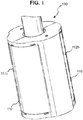
- Figure 1 shows a a control instrument 100 for a screwdriver.
- the control instrument has a handle 110.
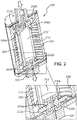
- the handle 110 is formed of two semi cylindrical components 112a, 112b and surrounds an aperture 200 (shown in figure 2 ) in the body of the device though which a K-wire can be passed.
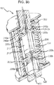
- the handle 110 is moveable from a first position (as shown in figures 1 and 2 ) to a second position (shown in figures 3a and 3b ), and is preferably resiliently biased into the first position.
- an additional cylindrical component 210 positioned within the aperture 200 of the device is an additional cylindrical component 210, having an aperture 212 extending therethrough.
- the K-wire passes through the aperture 212 of the cylindrical component 210.
- the cylindrical component 210 extends from a screw-engaging portion 120 of the device which protrudes from the device at a first end, and rotates therewith.
- the screw-engaging portion may engage a screw directly or may be connected to an existing screw driver.
- two gripping members 220a, 220b Positioned within the cylindrical component 210 are two gripping members 220a, 220b which are moveable between a first position, in which they allow passage of a K-wire therethrough, and a second position in which they are able to grip the K-wire.
- the gripping members 220a, 220b are positioned within a guide 250 disposed within the cylindrical component 210.
- the internal diameter of the semi cylindrical components 112a, 112b comprises a thread 230.
- the gripping members 220a, 220b have extensions 222a, 222b which extend outside the cylindrical component 210 and are engageable with the thread 230, when the semi cylindrical components 112a, 112b are moved into their second position, as shown in figure 3a .
- the control instrument 100 further includes comprises a T-handle (not shown) positioned at an end opposite the screw-engaging portion 120.
- the T-handle engages the cylindrical component 210 of the screw driver 100 to rotate it and thus the screw-engaging portion 120.
- the T-handle comprises protrusions 310a, 310b.
- the control instrument 100 further includes a locking component 320.
- the locking component 320 is rotatably connected to the cylindrical component 210 and has apertures 322a, 322b which correspond to the protrusions 310a, 310b on the T-handle.
- the locking component 320 is moveable along the axis of the device in a direction shown by arrow A from a first position, in which the apertures 322a, 322b are disengaged from the protrusions 310a, 310b on the T-handle and a second position in which the apertures 322a, 322b engage the protrusions 310a, 310b on the T-handle.
- the T-handle is rotatably connected, via the locking component 320, to the cylindrical component 210 and hence to the screw-engaging portion 120.
- the handle 110 further comprises projections 240a, 240b on its inner diameter, as shown in figure 2 .
- the projections 240a, 240b are positioned at an end of the handle 110 opposite the screw-engaging portion 120 of the device.
- the projections 240a, 240b include sloped surfaces 242a, 242b which engage with camming surfaces of the locking component 320 such that when the handle 110 is moved into its second position, the projections 240a, 240b act on the locking component 320, moving it axially in the direction of arrow A into its second position.
- the handle 110 is compressed into its second position, thereby moving the gripping members 220a, 220b into engagement with the K-wire 400 and moving the handle projections 240a, 240b into engagement with the locking component 320.
- the locking component 320 is moved in the direction of arrow A, by the projections 240a, 240b so that the protrusions 310a, 310b of the handle are inserted into the apertures 322a, 322b of the locking component 320.
- the T-handle is then rotatably engaged with the screw-engaging portion 120 as described above such that, as the T-handle is rotated in the direction shown by arrow B, the cylinder 210 and thus the screw engaging position 120 is rotated, screwing the pedicle screw into position.
- the gripping members 220a, 220b are also rotated and, by virtue of the thread 230 disposed on the interior of the handle 110, the gripping members 220a, 220b move in an axial direction towards the handle their movement directed by guide 250, along the direction of arrow A, thereby removing the K-wire 400 axially as the screw is inserted.
- the K-wire may be removed from its position or it may be retained in its initial position relative to the bone.
- control instrument may be an integral part of a screw driver or may be placed between the handle and screw-engaging portion of an existing instrument.
Landscapes
- Health & Medical Sciences (AREA)
- Orthopedic Medicine & Surgery (AREA)
- Life Sciences & Earth Sciences (AREA)
- Surgery (AREA)
- Neurology (AREA)
- Heart & Thoracic Surgery (AREA)
- General Health & Medical Sciences (AREA)
- Biomedical Technology (AREA)
- Nuclear Medicine, Radiotherapy & Molecular Imaging (AREA)
- Medical Informatics (AREA)
- Molecular Biology (AREA)
- Animal Behavior & Ethology (AREA)
- Engineering & Computer Science (AREA)
- Public Health (AREA)
- Veterinary Medicine (AREA)
- Dentistry (AREA)
- Oral & Maxillofacial Surgery (AREA)
- Surgical Instruments (AREA)
- Telephone Function (AREA)
Applications Claiming Priority (1)
| Application Number | Priority Date | Filing Date | Title |
|---|---|---|---|
| PCT/IB2013/051168 WO2014125328A1 (en) | 2013-02-13 | 2013-02-13 | Pedicle screw engaging control instrument with a guidewire capturing system |
Publications (2)
| Publication Number | Publication Date |
|---|---|
| EP2956072A1 EP2956072A1 (en) | 2015-12-23 |
| EP2956072B1 true EP2956072B1 (en) | 2019-12-18 |
Family
ID=48093032
Family Applications (1)
| Application Number | Title | Priority Date | Filing Date |
|---|---|---|---|
| EP13716047.9A Active EP2956072B1 (en) | 2013-02-13 | 2013-02-13 | Pedicle screw engaging control instrument with a guidewire capturing system |
Country Status (6)
| Country | Link |
|---|---|
| US (2) | US9949770B2 (cg-RX-API-DMAC7.html) |
| EP (1) | EP2956072B1 (cg-RX-API-DMAC7.html) |
| JP (1) | JP6271592B2 (cg-RX-API-DMAC7.html) |
| CN (1) | CN105163681B (cg-RX-API-DMAC7.html) |
| AU (2) | AU2013378522A1 (cg-RX-API-DMAC7.html) |
| WO (1) | WO2014125328A1 (cg-RX-API-DMAC7.html) |
Families Citing this family (4)
| Publication number | Priority date | Publication date | Assignee | Title |
|---|---|---|---|---|
| KR102303909B1 (ko) * | 2014-05-13 | 2021-09-24 | 삼성전자주식회사 | 휴대 단말기 및 차량용 어플리케이션 제어 방법 |
| US11759280B2 (en) * | 2020-02-06 | 2023-09-19 | Aesculap Ag | Surgical instrumentation for fixation of cervical spine |
| KR102402850B1 (ko) * | 2020-03-06 | 2022-05-27 | 울산대학교 산학협력단 | 시술도구 제어 장치 및 방법 |
| DE102022104674A1 (de) * | 2022-02-28 | 2023-08-31 | Aesculap Ag | Medizinische Bohrvorrichtung und medizinisches Bohrsystem |
Family Cites Families (19)
| Publication number | Priority date | Publication date | Assignee | Title |
|---|---|---|---|---|
| US3975032A (en) | 1974-04-15 | 1976-08-17 | Minnesota Mining And Manufacturing Company | Surgical wire driving assembly |
| JPS63100158A (ja) | 1986-10-15 | 1988-05-02 | Kobe Steel Ltd | 成形性にすぐれる高強度冷延鋼板 |
| JPS63100158U (cg-RX-API-DMAC7.html) * | 1986-12-22 | 1988-06-29 | ||
| JPH08257135A (ja) | 1995-03-23 | 1996-10-08 | Piolax Inc | 医療用ガイドワイヤの操作保持具 |
| DE19627864C2 (de) | 1996-07-11 | 2003-05-08 | Aesculap Ag & Co Kg | Chirurgische Spannvorrichtung |
| US5843001A (en) * | 1997-09-17 | 1998-12-01 | Goldenberg; Alec | Connector for a replaceable biopsy needle |
| US7081122B1 (en) * | 1999-10-19 | 2006-07-25 | Kyphon Inc. | Hand-held instruments that access interior body regions |
| US6564806B1 (en) * | 2000-02-18 | 2003-05-20 | Thomas J. Fogarty | Device for accurately marking tissue |
| US6827722B1 (en) * | 2001-12-11 | 2004-12-07 | Biomet, Inc. | Method and apparatus for use of a guide wire capturing surgical instrument |
| US20060089661A1 (en) | 2002-05-06 | 2006-04-27 | Dodge Brian C | Omni-actuable hand-held surgical instruments |
| US7207995B1 (en) * | 2004-01-29 | 2007-04-24 | Biomer Manufacturing Corp. | Method and apparatus for retaining a guide wire |
| EP1758518A2 (en) | 2004-06-07 | 2007-03-07 | Edwards Lifesciences Corporation | Methods and devices for directionally ablating tissue |
| US7938848B2 (en) | 2004-06-09 | 2011-05-10 | Life Spine, Inc. | Spinal fixation system |
| US20070161985A1 (en) * | 2005-12-05 | 2007-07-12 | Kentomia, Llc . | Screws configured to engage bones, and methods of attaching implants to skeletal regions |
| US8167899B2 (en) * | 2006-05-04 | 2012-05-01 | Warsaw Orthopedic, Inc. | Retractable stylet and cannula combination |
| US20090275992A1 (en) * | 2008-04-30 | 2009-11-05 | Phan Christopher U | Apparatus and methods for inserting facet screws |
| US8267873B2 (en) * | 2008-09-02 | 2012-09-18 | Olympus Medical Systems Corp. | Guidewire catheter |
| CN102413777B (zh) | 2009-03-12 | 2014-07-16 | 扩张整形外科公司 | 包括展开装置的骨植入和稳定组件 |
| US8641717B2 (en) * | 2010-07-01 | 2014-02-04 | DePuy Synthes Products, LLC | Guidewire insertion methods and devices |
-
2013
- 2013-02-13 AU AU2013378522A patent/AU2013378522A1/en not_active Abandoned
- 2013-02-13 JP JP2015557527A patent/JP6271592B2/ja active Active
- 2013-02-13 US US14/767,531 patent/US9949770B2/en active Active
- 2013-02-13 WO PCT/IB2013/051168 patent/WO2014125328A1/en not_active Ceased
- 2013-02-13 CN CN201380072951.3A patent/CN105163681B/zh active Active
- 2013-02-13 EP EP13716047.9A patent/EP2956072B1/en active Active
-
2018
- 2018-05-04 US US15/972,084 patent/US10709484B2/en active Active
- 2018-07-24 AU AU2018208641A patent/AU2018208641B2/en active Active
Non-Patent Citations (1)
| Title |
|---|
| None * |
Also Published As
| Publication number | Publication date |
|---|---|
| US20170014165A1 (en) | 2017-01-19 |
| JP6271592B2 (ja) | 2018-01-31 |
| CN105163681B (zh) | 2020-06-30 |
| US9949770B2 (en) | 2018-04-24 |
| EP2956072A1 (en) | 2015-12-23 |
| WO2014125328A1 (en) | 2014-08-21 |
| AU2013378522A1 (en) | 2015-10-01 |
| US10709484B2 (en) | 2020-07-14 |
| AU2018208641B2 (en) | 2019-09-12 |
| JP2016506850A (ja) | 2016-03-07 |
| AU2018208641A1 (en) | 2018-08-09 |
| CN105163681A (zh) | 2015-12-16 |
| US20180250037A1 (en) | 2018-09-06 |
Similar Documents
| Publication | Publication Date | Title |
|---|---|---|
| US11337733B2 (en) | Derotation apparatus for treating spinal irregularities | |
| AU2018208641B2 (en) | Pedicle screw engaging control instrument with a guidewire capturing system | |
| EP2918238B1 (en) | Instrument for holding and inserting a bone anchor | |
| EP2833813B1 (en) | Bone screw and self-retaining driver | |
| US9254160B2 (en) | Driver assembly with guidewire control mechanism | |
| US10441326B2 (en) | Driver instruments and related methods | |
| EP2601899A1 (en) | Apparatus for securing a spinal rod system | |
| US20110184469A1 (en) | Set screw alignment tool | |
| US20130103095A1 (en) | Facet Screw System and Method | |
| US20080147128A1 (en) | Cannulated bone screw and cannulated driver for the implantation thereof | |
| JP2016019728A5 (cg-RX-API-DMAC7.html) | ||
| CN108697444A (zh) | 用于将杆引导到植入物保持器中的器械 | |
| US10349985B1 (en) | Universal pedicle screw removal device and related methods | |
| JP2016506850A5 (cg-RX-API-DMAC7.html) | ||
| EP2777568B1 (en) | spinal rod insertion instrument | |
| WO2012127268A1 (en) | A fitting tool for a pedicular anchoring system | |
| US12213707B2 (en) | Medical decoupling instrument | |
| US20170151006A1 (en) | Medical cutting instrument |
Legal Events
| Date | Code | Title | Description |
|---|---|---|---|
| PUAI | Public reference made under article 153(3) epc to a published international application that has entered the european phase |
Free format text: ORIGINAL CODE: 0009012 |
|
| 17P | Request for examination filed |
Effective date: 20150730 |
|
| AK | Designated contracting states |
Kind code of ref document: A1 Designated state(s): AL AT BE BG CH CY CZ DE DK EE ES FI FR GB GR HR HU IE IS IT LI LT LU LV MC MK MT NL NO PL PT RO RS SE SI SK SM TR |
|
| AX | Request for extension of the european patent |
Extension state: BA ME |
|
| DAX | Request for extension of the european patent (deleted) | ||
| STAA | Information on the status of an ep patent application or granted ep patent |
Free format text: STATUS: EXAMINATION IS IN PROGRESS |
|
| 17Q | First examination report despatched |
Effective date: 20170712 |
|
| GRAP | Despatch of communication of intention to grant a patent |
Free format text: ORIGINAL CODE: EPIDOSNIGR1 |
|
| STAA | Information on the status of an ep patent application or granted ep patent |
Free format text: STATUS: GRANT OF PATENT IS INTENDED |
|
| INTG | Intention to grant announced |
Effective date: 20190527 |
|
| RIN1 | Information on inventor provided before grant (corrected) |
Inventor name: MUELLER, SARAH Inventor name: GUETLIN, MICHAEL Inventor name: STUCKI, JANICK |
|
| GRAJ | Information related to disapproval of communication of intention to grant by the applicant or resumption of examination proceedings by the epo deleted |
Free format text: ORIGINAL CODE: EPIDOSDIGR1 |
|
| STAA | Information on the status of an ep patent application or granted ep patent |
Free format text: STATUS: EXAMINATION IS IN PROGRESS |
|
| INTC | Intention to grant announced (deleted) | ||
| GRAR | Information related to intention to grant a patent recorded |
Free format text: ORIGINAL CODE: EPIDOSNIGR71 |
|
| GRAS | Grant fee paid |
Free format text: ORIGINAL CODE: EPIDOSNIGR3 |
|
| STAA | Information on the status of an ep patent application or granted ep patent |
Free format text: STATUS: GRANT OF PATENT IS INTENDED |
|
| GRAA | (expected) grant |
Free format text: ORIGINAL CODE: 0009210 |
|
| STAA | Information on the status of an ep patent application or granted ep patent |
Free format text: STATUS: THE PATENT HAS BEEN GRANTED |
|
| INTG | Intention to grant announced |
Effective date: 20191106 |
|
| AK | Designated contracting states |
Kind code of ref document: B1 Designated state(s): AL AT BE BG CH CY CZ DE DK EE ES FI FR GB GR HR HU IE IS IT LI LT LU LV MC MK MT NL NO PL PT RO RS SE SI SK SM TR |
|
| REG | Reference to a national code |
Ref country code: CH Ref legal event code: EP Ref country code: CH Ref legal event code: NV Representative=s name: E. BLUM AND CO. AG PATENT- UND MARKENANWAELTE , CH |
|
| REG | Reference to a national code |
Ref country code: IE Ref legal event code: FG4D |
|
| REG | Reference to a national code |
Ref country code: DE Ref legal event code: R096 Ref document number: 602013064078 Country of ref document: DE |
|
| REG | Reference to a national code |
Ref country code: AT Ref legal event code: REF Ref document number: 1213714 Country of ref document: AT Kind code of ref document: T Effective date: 20200115 |
|
| REG | Reference to a national code |
Ref country code: NL Ref legal event code: MP Effective date: 20191218 |
|
| PG25 | Lapsed in a contracting state [announced via postgrant information from national office to epo] |
Ref country code: GR Free format text: LAPSE BECAUSE OF FAILURE TO SUBMIT A TRANSLATION OF THE DESCRIPTION OR TO PAY THE FEE WITHIN THE PRESCRIBED TIME-LIMIT Effective date: 20200319 Ref country code: NO Free format text: LAPSE BECAUSE OF FAILURE TO SUBMIT A TRANSLATION OF THE DESCRIPTION OR TO PAY THE FEE WITHIN THE PRESCRIBED TIME-LIMIT Effective date: 20200318 Ref country code: LT Free format text: LAPSE BECAUSE OF FAILURE TO SUBMIT A TRANSLATION OF THE DESCRIPTION OR TO PAY THE FEE WITHIN THE PRESCRIBED TIME-LIMIT Effective date: 20191218 Ref country code: BG Free format text: LAPSE BECAUSE OF FAILURE TO SUBMIT A TRANSLATION OF THE DESCRIPTION OR TO PAY THE FEE WITHIN THE PRESCRIBED TIME-LIMIT Effective date: 20200318 Ref country code: SE Free format text: LAPSE BECAUSE OF FAILURE TO SUBMIT A TRANSLATION OF THE DESCRIPTION OR TO PAY THE FEE WITHIN THE PRESCRIBED TIME-LIMIT Effective date: 20191218 Ref country code: LV Free format text: LAPSE BECAUSE OF FAILURE TO SUBMIT A TRANSLATION OF THE DESCRIPTION OR TO PAY THE FEE WITHIN THE PRESCRIBED TIME-LIMIT Effective date: 20191218 Ref country code: FI Free format text: LAPSE BECAUSE OF FAILURE TO SUBMIT A TRANSLATION OF THE DESCRIPTION OR TO PAY THE FEE WITHIN THE PRESCRIBED TIME-LIMIT Effective date: 20191218 |
|
| REG | Reference to a national code |
Ref country code: LT Ref legal event code: MG4D |
|
| PG25 | Lapsed in a contracting state [announced via postgrant information from national office to epo] |
Ref country code: RS Free format text: LAPSE BECAUSE OF FAILURE TO SUBMIT A TRANSLATION OF THE DESCRIPTION OR TO PAY THE FEE WITHIN THE PRESCRIBED TIME-LIMIT Effective date: 20191218 Ref country code: HR Free format text: LAPSE BECAUSE OF FAILURE TO SUBMIT A TRANSLATION OF THE DESCRIPTION OR TO PAY THE FEE WITHIN THE PRESCRIBED TIME-LIMIT Effective date: 20191218 |
|
| PG25 | Lapsed in a contracting state [announced via postgrant information from national office to epo] |
Ref country code: AL Free format text: LAPSE BECAUSE OF FAILURE TO SUBMIT A TRANSLATION OF THE DESCRIPTION OR TO PAY THE FEE WITHIN THE PRESCRIBED TIME-LIMIT Effective date: 20191218 |
|
| PG25 | Lapsed in a contracting state [announced via postgrant information from national office to epo] |
Ref country code: EE Free format text: LAPSE BECAUSE OF FAILURE TO SUBMIT A TRANSLATION OF THE DESCRIPTION OR TO PAY THE FEE WITHIN THE PRESCRIBED TIME-LIMIT Effective date: 20191218 Ref country code: PT Free format text: LAPSE BECAUSE OF FAILURE TO SUBMIT A TRANSLATION OF THE DESCRIPTION OR TO PAY THE FEE WITHIN THE PRESCRIBED TIME-LIMIT Effective date: 20200513 Ref country code: CZ Free format text: LAPSE BECAUSE OF FAILURE TO SUBMIT A TRANSLATION OF THE DESCRIPTION OR TO PAY THE FEE WITHIN THE PRESCRIBED TIME-LIMIT Effective date: 20191218 Ref country code: NL Free format text: LAPSE BECAUSE OF FAILURE TO SUBMIT A TRANSLATION OF THE DESCRIPTION OR TO PAY THE FEE WITHIN THE PRESCRIBED TIME-LIMIT Effective date: 20191218 Ref country code: RO Free format text: LAPSE BECAUSE OF FAILURE TO SUBMIT A TRANSLATION OF THE DESCRIPTION OR TO PAY THE FEE WITHIN THE PRESCRIBED TIME-LIMIT Effective date: 20191218 |
|
| PG25 | Lapsed in a contracting state [announced via postgrant information from national office to epo] |
Ref country code: SM Free format text: LAPSE BECAUSE OF FAILURE TO SUBMIT A TRANSLATION OF THE DESCRIPTION OR TO PAY THE FEE WITHIN THE PRESCRIBED TIME-LIMIT Effective date: 20191218 Ref country code: SK Free format text: LAPSE BECAUSE OF FAILURE TO SUBMIT A TRANSLATION OF THE DESCRIPTION OR TO PAY THE FEE WITHIN THE PRESCRIBED TIME-LIMIT Effective date: 20191218 Ref country code: IS Free format text: LAPSE BECAUSE OF FAILURE TO SUBMIT A TRANSLATION OF THE DESCRIPTION OR TO PAY THE FEE WITHIN THE PRESCRIBED TIME-LIMIT Effective date: 20200418 |
|
| REG | Reference to a national code |
Ref country code: DE Ref legal event code: R097 Ref document number: 602013064078 Country of ref document: DE |
|
| REG | Reference to a national code |
Ref country code: AT Ref legal event code: MK05 Ref document number: 1213714 Country of ref document: AT Kind code of ref document: T Effective date: 20191218 |
|
| PLBE | No opposition filed within time limit |
Free format text: ORIGINAL CODE: 0009261 |
|
| STAA | Information on the status of an ep patent application or granted ep patent |
Free format text: STATUS: NO OPPOSITION FILED WITHIN TIME LIMIT |
|
| REG | Reference to a national code |
Ref country code: BE Ref legal event code: MM Effective date: 20200229 |
|
| PG25 | Lapsed in a contracting state [announced via postgrant information from national office to epo] |
Ref country code: MC Free format text: LAPSE BECAUSE OF FAILURE TO SUBMIT A TRANSLATION OF THE DESCRIPTION OR TO PAY THE FEE WITHIN THE PRESCRIBED TIME-LIMIT Effective date: 20191218 Ref country code: DK Free format text: LAPSE BECAUSE OF FAILURE TO SUBMIT A TRANSLATION OF THE DESCRIPTION OR TO PAY THE FEE WITHIN THE PRESCRIBED TIME-LIMIT Effective date: 20191218 Ref country code: ES Free format text: LAPSE BECAUSE OF FAILURE TO SUBMIT A TRANSLATION OF THE DESCRIPTION OR TO PAY THE FEE WITHIN THE PRESCRIBED TIME-LIMIT Effective date: 20191218 Ref country code: LU Free format text: LAPSE BECAUSE OF NON-PAYMENT OF DUE FEES Effective date: 20200213 |
|
| 26N | No opposition filed |
Effective date: 20200921 |
|
| PG25 | Lapsed in a contracting state [announced via postgrant information from national office to epo] |
Ref country code: SI Free format text: LAPSE BECAUSE OF FAILURE TO SUBMIT A TRANSLATION OF THE DESCRIPTION OR TO PAY THE FEE WITHIN THE PRESCRIBED TIME-LIMIT Effective date: 20191218 Ref country code: AT Free format text: LAPSE BECAUSE OF FAILURE TO SUBMIT A TRANSLATION OF THE DESCRIPTION OR TO PAY THE FEE WITHIN THE PRESCRIBED TIME-LIMIT Effective date: 20191218 |
|
| PG25 | Lapsed in a contracting state [announced via postgrant information from national office to epo] |
Ref country code: FR Free format text: LAPSE BECAUSE OF NON-PAYMENT OF DUE FEES Effective date: 20200218 Ref country code: IE Free format text: LAPSE BECAUSE OF NON-PAYMENT OF DUE FEES Effective date: 20200213 Ref country code: IT Free format text: LAPSE BECAUSE OF FAILURE TO SUBMIT A TRANSLATION OF THE DESCRIPTION OR TO PAY THE FEE WITHIN THE PRESCRIBED TIME-LIMIT Effective date: 20191218 |
|
| PG25 | Lapsed in a contracting state [announced via postgrant information from national office to epo] |
Ref country code: BE Free format text: LAPSE BECAUSE OF NON-PAYMENT OF DUE FEES Effective date: 20200229 Ref country code: PL Free format text: LAPSE BECAUSE OF FAILURE TO SUBMIT A TRANSLATION OF THE DESCRIPTION OR TO PAY THE FEE WITHIN THE PRESCRIBED TIME-LIMIT Effective date: 20191218 |
|
| PG25 | Lapsed in a contracting state [announced via postgrant information from national office to epo] |
Ref country code: TR Free format text: LAPSE BECAUSE OF FAILURE TO SUBMIT A TRANSLATION OF THE DESCRIPTION OR TO PAY THE FEE WITHIN THE PRESCRIBED TIME-LIMIT Effective date: 20191218 Ref country code: MT Free format text: LAPSE BECAUSE OF FAILURE TO SUBMIT A TRANSLATION OF THE DESCRIPTION OR TO PAY THE FEE WITHIN THE PRESCRIBED TIME-LIMIT Effective date: 20191218 Ref country code: CY Free format text: LAPSE BECAUSE OF FAILURE TO SUBMIT A TRANSLATION OF THE DESCRIPTION OR TO PAY THE FEE WITHIN THE PRESCRIBED TIME-LIMIT Effective date: 20191218 |
|
| PG25 | Lapsed in a contracting state [announced via postgrant information from national office to epo] |
Ref country code: MK Free format text: LAPSE BECAUSE OF FAILURE TO SUBMIT A TRANSLATION OF THE DESCRIPTION OR TO PAY THE FEE WITHIN THE PRESCRIBED TIME-LIMIT Effective date: 20191218 |
|
| REG | Reference to a national code |
Ref country code: CH Ref legal event code: U11 Free format text: ST27 STATUS EVENT CODE: U-0-0-U10-U11 (AS PROVIDED BY THE NATIONAL OFFICE) Effective date: 20260301 |
|
| PGFP | Annual fee paid to national office [announced via postgrant information from national office to epo] |
Ref country code: GB Payment date: 20260106 Year of fee payment: 14 |
|
| PGFP | Annual fee paid to national office [announced via postgrant information from national office to epo] |
Ref country code: DE Payment date: 20251230 Year of fee payment: 14 |
|
| PGFP | Annual fee paid to national office [announced via postgrant information from national office to epo] |
Ref country code: CH Payment date: 20260301 Year of fee payment: 14 |