EP2955982A2 - Plattierorgan eines werkstücks auf einer oberfläche - Google Patents
Plattierorgan eines werkstücks auf einer oberfläche Download PDFInfo
- Publication number
- EP2955982A2 EP2955982A2 EP15178705.8A EP15178705A EP2955982A2 EP 2955982 A2 EP2955982 A2 EP 2955982A2 EP 15178705 A EP15178705 A EP 15178705A EP 2955982 A2 EP2955982 A2 EP 2955982A2
- Authority
- EP
- European Patent Office
- Prior art keywords
- power
- electronic
- housing
- rod
- bearing surface
- Prior art date
- Legal status (The legal status is an assumption and is not a legal conclusion. Google has not performed a legal analysis and makes no representation as to the accuracy of the status listed.)
- Withdrawn
Links
Images

Classifications
-
- H—ELECTRICITY
- H05—ELECTRIC TECHNIQUES NOT OTHERWISE PROVIDED FOR
- H05K—PRINTED CIRCUITS; CASINGS OR CONSTRUCTIONAL DETAILS OF ELECTRIC APPARATUS; MANUFACTURE OF ASSEMBLAGES OF ELECTRICAL COMPONENTS
- H05K7/00—Constructional details common to different types of electric apparatus
- H05K7/14—Mounting supporting structure in casing or on frame or rack
- H05K7/1422—Printed circuit boards receptacles, e.g. stacked structures, electronic circuit modules or box like frames
- H05K7/1427—Housings
- H05K7/1432—Housings specially adapted for power drive units or power converters
- H05K7/14322—Housings specially adapted for power drive units or power converters wherein the control and power circuits of a power converter are arranged within the same casing
-
- H—ELECTRICITY
- H05—ELECTRIC TECHNIQUES NOT OTHERWISE PROVIDED FOR
- H05K—PRINTED CIRCUITS; CASINGS OR CONSTRUCTIONAL DETAILS OF ELECTRIC APPARATUS; MANUFACTURE OF ASSEMBLAGES OF ELECTRICAL COMPONENTS
- H05K7/00—Constructional details common to different types of electric apparatus
- H05K7/20—Modifications to facilitate cooling, ventilating, or heating
- H05K7/2089—Modifications to facilitate cooling, ventilating, or heating for power electronics, e.g. for inverters for controlling motor
- H05K7/209—Heat transfer by conduction from internal heat source to heat radiating structure
Definitions
- the present invention relates to a plating member and a power block, in particular for an inverter, in particular mounted at the terminals of a high-voltage battery of an electric vehicle.
- the power unit comprises at least one electronic power module, preferably a plurality of electronic power modules.
- Power modules intended to be part of such a power unit are already known in the prior art, in particular isolated molded connection grid power modules or IML module (for "Insulated Molded Leadframe” in English) of the patent. French N ° 0116153 in the name of the plaintiff.
- the power module comprises a housing in which are housed one or more electronic power components.
- the power unit further comprises at least one electronic control board.
- the electronic control board is typically a printed circuit board (PCB).
- the power module and the electronic control board are electrically connected to provide power block functions.
- the module and the card are housed in a casing of the power block.
- the inadvertent heating of the electronic power modules damages their reliability and causes damage, in particular to their power components, which has a detrimental effect on the service life of the power unit.
- a coolant is in contact with the bottom of the housing.
- the mechanical connection between the first end and the support makes it possible to fix the first end of the deformable element to the support.
- the first end may be secured to the support directly or via elements located between the first end and the support.
- elastically deformable element an element that returns to an initial position in the absence of stress.
- the elastically deformable element exerts a force on the piece to keep it in contact with the bearing surface.
- the support of the workpiece on the surface is achieved by the engagement of a screw.
- the support of the piece on the surface is formed by the elastically deformable element via its second end.
- the axis of the deformable element may be in a direction transverse to the bearing surface, and the plating member presses the part in a direction transverse to the bearing surface.
- the elastically deformable element comprises at least one spring.
- the elastically deformable element comprises two coaxial springs of different resonance frequencies.
- the plating member further comprises a rod mounted in the axis of the deformable element, the rod being intended to participate in the mechanical connection between the first end and the support.
- the rod makes it possible to fix the first end of the deformable element to the support via the support surface.
- the mechanical connection between the first end and the support is obtained simply.
- the rod has a portion integral with the first end of the deformable element, and a portion intended to engage with the bearing surface.
- the rod has a first portion of large diameter, a second portion of small diameter and a third portion intended to engage with the surface, said second portion being mounted in the axis of the deformable element, and said first portion being intended to press the first end of the deformable element when the third portion engages the surface.
- the second end of the deformable element exerts a force on the workpiece when the third portion engages the surface.
- the plating member further comprises a spacer in which the deformable element is mounted, the spacer comprising at least one radial portion extending in a direction transverse to the axis of the deformable element, said radial portion being intended to be taken between the second end of the deformable element and the workpiece when the second end exert an effort on the said room.
- the elastically deformable element bears on the radial portion when it exerts a force on said part.
- the spacer or barrel may have an empty internal portion of material for receiving the deformable element or the rod.
- the spacer may extend along an axis parallel to the axis of the deformable element.
- the spacer has a circular or polygonal cross section.
- the spacer may be of a rigid material.
- the spacer serves to guide the elastically deformable element.
- the spacer prevents deformations of the deformable element in a direction transverse to the axis of the element.
- the radial portion of the spacer has an opening allowing the passage of the rod.
- the present invention also relates to a power unit comprising a casing having a bearing surface on which at least one electronic power module rests, the or each electronic power module comprising at least one electronic power component, characterized in that that he understands at least one plating member according to the invention plating the power module on said bearing surface.
- the electronic power module comprises a housing in which are housed the electronic power component or components.
- the bearing surface is a bottom of the housing.
- the bearing surface may be a thermal dissipation surface of the housing.
- the power block further comprises at least one structure vis-à-vis the power module, said structure being fixed to the casing of the power block, and said structure being associated with said plating member.
- the structure may be associated with the plating member via the first end of the deformable element or the rod of the plating member.
- the structure participates in the mechanical connection between the first end of the deformable element of the plating member and the housing.
- the plating member exerts a force on the power module from the structure vis-à-vis the power module.
- the plating member exerts a pressure on the electronic power module, in particular on a casing of the power module, to keep it in contact with said bearing surface of the casing.
- the plating member maintains a position of the electronic power module 21 in a direction transverse to the bearing surface. Thanks to the plating member associated with the structure, the power module is pressed against the support surface in a durable manner.
- the plating member is not between the bearing surface and the power module and is therefore less sensitive to vibrations experienced by the electronic power module.
- said structure comprises at least one beam substantially parallel to said bearing surface and fixed to the casing, and the cladding member is mounted between the beam and the electronic power module.
- the structure can be a plan or have another form.
- the first end of the elastically deformable element can be held by the beam, the second end exerting a mechanical force on the power module, in particular on the power module housing.
- the beam being held fixed by the casing, the plating member exerts a force on the power module from the beam.
- the first end of the deformable element of the plating member is in mechanical connection with the support (here the casing) at least via the beam.
- said structure is fixed to the housing at side walls of the housing.
- a side wall is for example a wall surrounding the bearing surface.
- the wall may be substantially transverse to the bearing surface.
- the power unit comprises a plating member having said rod, and said structure is fixed to said bearing surface of the housing at least via the rod.
- a portion of the rod bears against a countersink of the structure.
- the structure is fixed to the casing by the plating member.
- the arrangement of the structure in the power block is simplified.
- said structure rests on at least one stop located on a side wall of the housing. For example, by engaging the rod in the bearing surface, the structure bears against the stop.
- the power unit comprises a plating member having said spacer and said spacer is integral with said structure.
- said structure supports at least one electronic control board vis-à-vis the power electronic module.
- the power unit comprises a plating member having said rod and the electronic control board is fixed to the structure via the rod.
- the plating member ensures the attachment of the structure to the housing and also the maintenance of the electronic card on the structure.
- the arrangement of the structure, the power module and the electronic card is simplified.
- the position of the electronic power module on the support surface is maintained by at least one fastener.
- the fastener improves the positioning of the power module on the support surface by avoiding lateral displacement of the module on the surface.
- the fastener maintains a position of the electronic power module 21 in a direction parallel to the bearing surface.
- the fixing member is a pin or a cylinder integral with the power module casing, which is inserted into force in a hole of the bearing surface.
- the fastener is a screw inserted into an eyelet of a bracket of the housing and screwed into a hole of the housing.
- the power unit comprises a plating member having said rod and said electronic module fixing member comprises said rod.
- said rod also maintains the lateral position of the power module on the support surface.
- the present invention also relates to an inverter for an electric vehicle comprising a power unit according to the invention.
- the invention also relates to an electric vehicle comprising a battery, in particular at high voltage, a socket for recharging the battery by an electrical network and an inverter according to the invention mounted between the battery and the socket.
- the invention also relates to a member for plating a workpiece on a surface of a support, said member comprising an elastically deformable element extending along an axis, said element having a first end intended to be in mechanical connection with said support, and a second end intended to exert a force on said part, said elastically deformable element comprising at least one spring.
- the invention further relates to a member for plating a workpiece on a surface of a support, said member comprising an elastically deformable element extending along an axis, said element having a first end intended to be in mechanical connection with said support, and a second end intended to exert a force on said part, said elastically deformable member comprising at least one spring; and the plating member further comprising a spacer in which the spring is mounted, the spacer comprising at least one radial portion extending in a direction transverse to the axis of the deformable element, said radial portion being intended to be taken between the second end of the deformable element and the workpiece when the second end exerts a force on said workpiece.
- the cladding members may comprise any of the features described above.
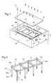
- the figure 1 represents an example of power block 1 according to one embodiment.
- the power block 1 comprises a housing 20 in which a plurality of power modules 21 are received.
- the power modules 21 are, for example, IML modules.
- the power unit 1 comprises in particular six modules 21 arranged in two rows of three modules on a support surface 5.
- the bearing surface 5 is preferably made of a metallic material, for example cast iron.
- the bearing surface 5 is a bottom of the housing 20.
- the bearing surface 5 is integral with the side walls of the housing 20.
- the bearing surface is for example a heat dissipation surface of the housing 20.
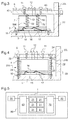
- the IML module 21 comprises a housing 2 in which are housed one or more electronic power components 16 ( Figures 3 and 4 ). Electrical connection pads 4 protrude on the top of the housing 2 to provide electrical connection with an electronic card 6 for example. These studs 4 comprise connection points 14, in particular via wires 12 of electrical connection ("bonding" in English), in particular ultrasonically welded to the card 6 (FIG. Figures 3 and 4 ).
- conductive blades 15 for example copper, on which are mounted the electronic components 16 power.
- the Power electronic components 16 may be in particular bipolar components such as a diode, three-pole components such as a MOS or IGBT type transistor or a more complex component such as an ASIC integrated circuit or the like.
- the conductive blades 15 are separated from each other by a dielectric material in the interstices 17 between the blades.
- the housing 2 is filled with a gel, in particular silicone, or a resin, in particular an epoxy resin, to protect the electronic components 16 of power.
- the conductive blades 15 protrude outside the housing 2 of the electronic module 21 power laterally for inter alia a connection to a power network and / or a module 21 neighbor.
- the conductive blades 15 and the electrically insulating dielectric material in the interstices 17 form the bottom of the electronic power module 21 and thus be in contact with the bearing surface 5 of the casing 20.
- the structure is a frame 42, which consists of at least two longitudinal beams 40, 41 and transverse beams 44 intended to extend on either side of the power block facing the power modules 21.
- the structure 32, 33, 42 is associated with at least one plating member 100, 200, 250, 500 for pressing the power modules 21 against the bearing surface 5.
- the plating member 100, 200, 250, 500 comprises at least one elastically deformable element disposed between the structure 32, 33, 42 and the electronic power module 21.
- the deformable element comprises a spring 43.
- the deformable element comprises two springs 22, 23; 52, 53.
- the two springs 22, 23; 52, 53 are coaxial and of different resonance frequencies. This gives a greater stability of the plating.
- the spring 43 and the two springs 22, 23; 52, 53, provide downward compression of the electronic module 21 of power to thereby maintain the electronic module 21 power in contact with its bottom with the bearing surface 5 of the casing of the power block.
- the heat that is created inside the electronic module 21 of power is discharged by the bottom thereof and by the bearing surface 5 of the casing of the power block.
- the materials of the support surface 5 and the bottom of the power electronic module 21 are preferably chosen so as to promote this heat exchange.
- the structure 32, 33, 42 is secured to the casing 20 of the power block.
- the structure 42, 44 is fixed to the casing 20 of the power block at the side walls 20L of the casing.
- Springs 43; 52, 53 are arranged between the beam or beams 40, 41 of the frame 42, 44 and the electronic power modules 21. These springs 43; 52, 53 come to bear against the beams from below, that is to say from the face of the beams which is opposite the electronic modules 21, and press the electronic modules 21 down, that is to say say towards the support surface 5.
- the fastening of the structure 32 to the housing 20 is formed by a rod 24 mounted in the axis of the spring 22, 23.
- the rod 24 is a screw rod.
- the springs 22, 23 extend along the rod 24 from the frame 32.
- the rod 24 engages in a hole of the bearing surface 5, for example by a thread of the rod 24 and the hole.
- the figure 2 shows an example of structure having the form of a frame 32 comprising screws for fixing the structure 32 to the bearing surface 5 of the housing.
- the structure 32 comprises two longitudinal beams 30, 31 interconnected by transverse beams 34.
- the frame 32 has at least one counterbore which allows the rod 24 to pass and which provides a bearing surface for a thicker portion of the beam.
- rod such as a screw head 24a.
- the rod 24 can engage with the bearing surface 5 via a threaded portion 24c.
- the spring can be mounted around a portion 24b of small diameter.
- the casing 20 comprises at least one abutment 20B at the side walls 20L of the casing 20.
- the structure 32 bears on the abutment 20B, after the engagement of the rod 24 in the support surface 5.
- the abutment 20B makes it possible to control the distance between the structure 32 and the electronic power module 21, and to improve the stability of the structure 32.
- the plating member 250 further comprises a spacer 25 in which is mounted the deformable element 22, 23.
- the spacer 25 may be integral with the structure 33 at one of its ends. Another end comprising a radial portion 25R may abut on the electronic power module 21 under the effect of the force exerted by the second end of the deformable element.
- a fixing member 3 maintains the position of the power module 21 on the bearing surface 5.
- the fixing member 3 makes it possible to avoid movements of the electronic power module 21 in directions other than the direction plating.
- each power module 21 comprises ear-shaped fastening tabs 10 that project laterally from each casing 2. These lugs 10 or lugs are intended to receive the fastening members 3. The fastening is ensured for example by screwing each housing 2 to the bearing surface 5 of the housing.
- independent screws 3 secure the lugs 10 of the electronic power modules 21 to the bearing surface 5 of the casing 20.
- the fastening member comprises the fastening rod of the structure 32 with the bearing surface 5.
- the rod 24 maintains the lateral position of the power module 21 by being introduced into the ears 10 of the each electronic module 21 of power.
- the maintenance of the power module 21 is carried out with the fastening rod 24 of the structure 32 on the casing 20.
- At least one control electronic card 6 is arranged opposite the electronic power modules 21.
- the electronic card 6 is electrically connected to the electronic power module 21 by electrical connection wires 12.
- the control electronic card 6 delivers control signals for controlling the power components 16.
- the control electronic card 6 is for example a printed circuit board or PCB (for "printed circuit board" in English).
- the structure 32, 33, 42 is intended to support the control electronic card 6 vis-à-vis the electronic power module 21, in particular on at least one extension of the card 6.
- the structure 32, 33, 42 is coated with a plastic overmoulding to insure the electronic control card 6.
- the electronic card 6 is fixed to the structure 32, 33, 42 by being screwed in particular by screws 11 respectively.
- control electronic card 6 is fixed to the structure 32 via the rod 24 for fixing the structure 32 to the bearing surface 5.
- the figure 8 shows an example of a plating member according to one embodiment.
- the plating member 250 makes it possible to press a piece against a bearing surface 5.
- the piece is for example an electronic power module 21, in particular a fixing lug 10 of the electronic module 21.
- the plating member 250 comprises an elastically deformable element as described above, consisting for example of two coaxial springs 22, 23.
- the plating member 250 may comprise a rod 24 mounted in the axis of the two springs 22, 23.
- the rod 24 makes it possible to make the mechanical connection between a first end of the two springs 22, 23 and the bearing surface 5.
- the rod 24 may comprise a first portion 24a of large diameter, a second portion 24b of small diameter and a third portion 24c intended to engage with the surface 5.
- the second portion 24b can be mounted in the axis of the two springs 22, 23.
- the first portion 24a of the rod can bear on the first end of the two springs 22, 23 when the third portion 24b engages the surface support 5.
- the third portion 24c of the rod 24 engages with the bearing surface 5 via a thread, or by snapping, or by any other securing means.
- the rod 24 passes through the piece 10 to engage with the bearing surface 5.
- the piece 10 has a hole with a diameter greater than a transverse dimension of the rod 24.
- the rod 24 is thus preserved from the vibrations of the part 10, which improves the lifetime of the plating member.
- the plating member 250 may further comprise a spacer 25 in which the two springs 22, 23 are mounted.
- the spacer 25 comprises at least 25R radial portion extending in a direction transverse to the axis of the deformable element.
- the radial portion 25R is for example an edge of one end of the spacer 25, or an outgrowth on an inner wall of the spacer 25.
- the radial portion 25R is taken between the second end of the deformable element and the part 10.
- the second end of the deformable element then exerts a force on the piece 10 via the radial portion 25R.
- the spacer 25 is held by the deformable element.
- an electric vehicle comprising an inverter 90 according to the invention.
- the inverter 90 is mounted between a high voltage battery 50 and an electrical machine 80 for supplying the electrical machine 80 with energy.
- the inverter 90 comprises a power block 1 having six electronic power modules 21; and may comprise two filtering devices 60, 70 respectively mounted upstream and downstream of the block 1.
- the electronic power units 1 convert in particular a direct current coming from the battery 50 into an alternating current to power the electrical machine 80.
- the invention is not limited to the examples described.
- the embodiments of the plating member can be combined with each other. It is the same for the embodiments of the power block.
- the embodiments of the member and the block can be combined with one another.
Landscapes
- Engineering & Computer Science (AREA)
- Microelectronics & Electronic Packaging (AREA)
- Physics & Mathematics (AREA)
- Thermal Sciences (AREA)
- Electroplating Methods And Accessories (AREA)
- Battery Mounting, Suspending (AREA)
- Clamps And Clips (AREA)
Applications Claiming Priority (2)
| Application Number | Priority Date | Filing Date | Title |
|---|---|---|---|
| FR1158090A FR2979961B1 (fr) | 2011-09-12 | 2011-09-12 | Organe de plaquage d'une piece sur une surface |
| EP12762346.0A EP2756743B1 (de) | 2011-09-12 | 2012-08-31 | Element zum festen pressen eines bauteils an eine oberfläche |
Related Parent Applications (2)
| Application Number | Title | Priority Date | Filing Date |
|---|---|---|---|
| EP12762346.0A Division-Into EP2756743B1 (de) | 2011-09-12 | 2012-08-31 | Element zum festen pressen eines bauteils an eine oberfläche |
| EP12762346.0A Division EP2756743B1 (de) | 2011-09-12 | 2012-08-31 | Element zum festen pressen eines bauteils an eine oberfläche |
Publications (2)
| Publication Number | Publication Date |
|---|---|
| EP2955982A2 true EP2955982A2 (de) | 2015-12-16 |
| EP2955982A3 EP2955982A3 (de) | 2016-02-10 |
Family
ID=46889345
Family Applications (3)
| Application Number | Title | Priority Date | Filing Date |
|---|---|---|---|
| EP15178707.4A Withdrawn EP2955983A1 (de) | 2011-09-12 | 2012-08-31 | Plattierorgan eines werkstücks auf einer oberfläche |
| EP12762346.0A Active EP2756743B1 (de) | 2011-09-12 | 2012-08-31 | Element zum festen pressen eines bauteils an eine oberfläche |
| EP15178705.8A Withdrawn EP2955982A3 (de) | 2011-09-12 | 2012-08-31 | Plattierorgan eines werkstücks auf einer oberfläche |
Family Applications Before (2)
| Application Number | Title | Priority Date | Filing Date |
|---|---|---|---|
| EP15178707.4A Withdrawn EP2955983A1 (de) | 2011-09-12 | 2012-08-31 | Plattierorgan eines werkstücks auf einer oberfläche |
| EP12762346.0A Active EP2756743B1 (de) | 2011-09-12 | 2012-08-31 | Element zum festen pressen eines bauteils an eine oberfläche |
Country Status (3)
| Country | Link |
|---|---|
| EP (3) | EP2955983A1 (de) |
| FR (1) | FR2979961B1 (de) |
| WO (1) | WO2013038090A2 (de) |
Cited By (1)
| Publication number | Priority date | Publication date | Assignee | Title |
|---|---|---|---|---|
| CN108916296A (zh) * | 2018-05-11 | 2018-11-30 | 许继电气股份有限公司 | 一种换流阀阀厅 |
Families Citing this family (6)
| Publication number | Priority date | Publication date | Assignee | Title |
|---|---|---|---|---|
| FR3068841B1 (fr) | 2017-07-07 | 2019-08-23 | Alstom Transport Technologies | Dispositif de commutation electrique et coffre de traction electrique associe |
| FR3089750B1 (fr) * | 2018-12-11 | 2021-07-16 | Valeo Equip Electr Moteur | Convertisseur de tension et procédé de fabrication d’un convertisseur de tension |
| FR3091012B1 (fr) * | 2018-12-21 | 2021-01-15 | Valeo Siemens Eautomotive France Sas | Ensemble comprenant un dispositif electrique, un organe de plaquage et une piece de maintien de l’organe de plaquage |
| DE102019102165A1 (de) * | 2019-01-29 | 2020-07-30 | Endress + Hauser Flowtec Ag | Messumformer und Messgerät der Mess- und Automatisierungstechnik |
| CN111263549B (zh) * | 2020-03-10 | 2020-12-01 | 深圳市麦电创新科技有限公司 | 一种电源适配器保护装置 |
| CN111405793B (zh) * | 2020-04-02 | 2021-06-11 | 福建省闽发铝业股份有限公司 | 一种镀膜铝合金模板 |
Citations (5)
| Publication number | Priority date | Publication date | Assignee | Title |
|---|---|---|---|---|
| EP0711107A2 (de) * | 1994-11-07 | 1996-05-08 | Atlas Copco Controls Ab, Tyresö | Steuerschaltungsvorrichtung |
| US5563447A (en) * | 1993-09-07 | 1996-10-08 | Delco Electronics Corp. | High power semiconductor switch module |
| US5793106A (en) * | 1995-02-28 | 1998-08-11 | Hitachi, Ltd. | Semiconductor device |
| US20030175091A1 (en) * | 2000-03-10 | 2003-09-18 | Aukzemas Thomas V. | Floating captive screw |
| EP2745662A1 (de) * | 2011-08-19 | 2014-06-25 | Valeo Systèmes de Contrôle Moteur | Leistungsblock für einen wechselstromumrichter, wechselstromumrichter und elektrisches fahrzeug umfassend einen solchen leistungsblock |
Family Cites Families (7)
| Publication number | Priority date | Publication date | Assignee | Title |
|---|---|---|---|---|
| JPS5576232A (en) * | 1978-12-01 | 1980-06-09 | Tomoe Kogyo Kk | Vibration insulating device |
| US6679712B2 (en) * | 2002-06-19 | 2004-01-20 | Guo-Heng Chang | Fixture for an electrical device |
| DE20319489U1 (de) * | 2003-12-16 | 2004-04-01 | Ksb Aktiengesellschaft | Explosionsgeschütztes Gehäuse |
| DE102004031623B4 (de) * | 2004-06-30 | 2007-12-13 | Infineon Technologies Ag | Leistungs-Halbleitermodul mit federndem Anschlusskontakt |
| JP4404726B2 (ja) * | 2004-08-31 | 2010-01-27 | 三菱電機株式会社 | 車載用電力変換装置 |
| JP2009043775A (ja) * | 2007-08-06 | 2009-02-26 | Nissan Motor Co Ltd | 半導体装置 |
| AT507352B1 (de) * | 2008-10-01 | 2013-04-15 | Siemens Ag | Kühlanordnung |
-
2011
- 2011-09-12 FR FR1158090A patent/FR2979961B1/fr active Active
-
2012
- 2012-08-31 EP EP15178707.4A patent/EP2955983A1/de not_active Withdrawn
- 2012-08-31 EP EP12762346.0A patent/EP2756743B1/de active Active
- 2012-08-31 EP EP15178705.8A patent/EP2955982A3/de not_active Withdrawn
- 2012-08-31 WO PCT/FR2012/051967 patent/WO2013038090A2/fr not_active Ceased
Patent Citations (5)
| Publication number | Priority date | Publication date | Assignee | Title |
|---|---|---|---|---|
| US5563447A (en) * | 1993-09-07 | 1996-10-08 | Delco Electronics Corp. | High power semiconductor switch module |
| EP0711107A2 (de) * | 1994-11-07 | 1996-05-08 | Atlas Copco Controls Ab, Tyresö | Steuerschaltungsvorrichtung |
| US5793106A (en) * | 1995-02-28 | 1998-08-11 | Hitachi, Ltd. | Semiconductor device |
| US20030175091A1 (en) * | 2000-03-10 | 2003-09-18 | Aukzemas Thomas V. | Floating captive screw |
| EP2745662A1 (de) * | 2011-08-19 | 2014-06-25 | Valeo Systèmes de Contrôle Moteur | Leistungsblock für einen wechselstromumrichter, wechselstromumrichter und elektrisches fahrzeug umfassend einen solchen leistungsblock |
Cited By (1)
| Publication number | Priority date | Publication date | Assignee | Title |
|---|---|---|---|---|
| CN108916296A (zh) * | 2018-05-11 | 2018-11-30 | 许继电气股份有限公司 | 一种换流阀阀厅 |
Also Published As
| Publication number | Publication date |
|---|---|
| EP2756743B1 (de) | 2016-01-20 |
| EP2756743A2 (de) | 2014-07-23 |
| EP2955983A1 (de) | 2015-12-16 |
| WO2013038090A3 (fr) | 2014-03-20 |
| EP2955982A3 (de) | 2016-02-10 |
| FR2979961B1 (fr) | 2014-06-20 |
| FR2979961A1 (fr) | 2013-03-15 |
| WO2013038090A2 (fr) | 2013-03-21 |
Similar Documents
| Publication | Publication Date | Title |
|---|---|---|
| EP2756743B1 (de) | Element zum festen pressen eines bauteils an eine oberfläche | |
| EP2745662B1 (de) | Leistungsblock für einen wechselstromumrichter, wechselstromumrichter und elektrisches fahrzeug umfassend einen solchen leistungsblock | |
| EP3621093B1 (de) | Kapazitiver block mit einem kühlkörper | |
| EP3871296A1 (de) | Verbindungsvorrichtung für ein mit einem temperatursensor ausgestattetes fahrzeug | |
| EP2891178B1 (de) | Körper zum pressen eines teils auf eine oberfläche | |
| FR3011713A1 (fr) | Module electrique, systeme electrique comportant un tel module electrique, procedes de fabrication correspondants | |
| FR3097095A1 (fr) | Équipement electrique comprenant un élément élastique de fixation | |
| EP1912261A1 (de) | Elektrische Anschlussvorrichtung, insbesondere für elektrischen Sonnenkollektor | |
| EP2745661B1 (de) | Elektrische verbindungsvorrichtung, anordnung mit einer solchen vorrichtung und elektronikplatine sowie verfahren zum elektrischen anschluss einer elektronikplatine | |
| FR2794299A1 (fr) | Porte-balais a composant de commande pour alternateur de vehicule automobile | |
| WO2013053476A2 (fr) | Systeme de maintien mecanique, ensemble comprenant un tel systeme et une carte electronique et procede d'assemblage sur une surface d'un tel systeme et d'une telle carte | |
| FR2984680A1 (fr) | Structure portant un ou plusieurs composants electroniques | |
| EP4631322A1 (de) | Verbinderführung für einen wechselrichter mit einem presselement | |
| EP3667688B1 (de) | Elektrische einheit, die ein kapazitives element umfasst | |
| WO2020120245A1 (fr) | Ensemble d'un bloc capacitif avec organes de retenue intégrés | |
| FR2936915A1 (fr) | Machine electrique tournante comportant un agencement de redressement de courant et de regulation de tension. | |
| FR2926170A1 (fr) | Machine electrique tournante, notamment un alternateur pour vehicule automobile. | |
| FR3138011A1 (fr) | Ensemble de connexion à une borne d’un module de batterie d’accumulateurs | |
| FR2836773A1 (fr) | Dispositif de connexion d'un conducteur electrique a une carte a circuit imprime | |
| EP4179569A1 (de) | Elektronisches leistungsmodul, elektrisches system mit solch einem modul und zugehörige herstellungsverfahren | |
| WO2026032919A1 (fr) | Dispositif de dissipation thermique ainsi que boîtier de connexion électrique, dispositif de stockage d'énergie électrique et véhicule comprenant un tel dispositif de dissipation | |
| FR2900767A1 (fr) | Macro-composant destine a etre monte dans un ensemble a empilement presse et ensemble comportant un tel macro-composant | |
| EP1371113A1 (de) | Stromverbinder für eine gedruckte schaltung | |
| FR2949615A1 (fr) | Dispositif de raccordement electrique particulierement adapte aux panneaux solaires electriques ou a d'autres producteurs d'energie | |
| EP1852912A1 (de) | Vorrichtung und Verfahren zum Zentrieren eines Halbleiterelements, das in eine komprimierte Stapelanordnung eingefügt werden soll, und komprimierte Stapelanordnung, die eine solche Vorrichtung umfasst |
Legal Events
| Date | Code | Title | Description |
|---|---|---|---|
| PUAI | Public reference made under article 153(3) epc to a published international application that has entered the european phase |
Free format text: ORIGINAL CODE: 0009012 |
|
| AC | Divisional application: reference to earlier application |
Ref document number: 2756743 Country of ref document: EP Kind code of ref document: P |
|
| AK | Designated contracting states |
Kind code of ref document: A2 Designated state(s): AL AT BE BG CH CY CZ DE DK EE ES FI FR GB GR HR HU IE IS IT LI LT LU LV MC MK MT NL NO PL PT RO RS SE SI SK SM TR |
|
| PUAL | Search report despatched |
Free format text: ORIGINAL CODE: 0009013 |
|
| AK | Designated contracting states |
Kind code of ref document: A3 Designated state(s): AL AT BE BG CH CY CZ DE DK EE ES FI FR GB GR HR HU IE IS IT LI LT LU LV MC MK MT NL NO PL PT RO RS SE SI SK SM TR |
|
| RIC1 | Information provided on ipc code assigned before grant |
Ipc: H05K 7/14 20060101AFI20160106BHEP Ipc: H05K 7/20 20060101ALI20160106BHEP |
|
| 17P | Request for examination filed |
Effective date: 20160616 |
|
| RBV | Designated contracting states (corrected) |
Designated state(s): AL AT BE BG CH CY CZ DE DK EE ES FI FR GB GR HR HU IE IS IT LI LT LU LV MC MK MT NL NO PL PT RO RS SE SI SK SM TR |
|
| 17Q | First examination report despatched |
Effective date: 20170310 |
|
| STAA | Information on the status of an ep patent application or granted ep patent |
Free format text: STATUS: THE APPLICATION IS DEEMED TO BE WITHDRAWN |
|
| 18D | Application deemed to be withdrawn |
Effective date: 20190328 |