EP2955466B1 - Temperature treatment apparatus and method for solidifying portions of fluid - Google Patents
Temperature treatment apparatus and method for solidifying portions of fluid Download PDFInfo
- Publication number
- EP2955466B1 EP2955466B1 EP14172406.2A EP14172406A EP2955466B1 EP 2955466 B1 EP2955466 B1 EP 2955466B1 EP 14172406 A EP14172406 A EP 14172406A EP 2955466 B1 EP2955466 B1 EP 2955466B1
- Authority
- EP
- European Patent Office
- Prior art keywords
- temperature treatment
- fluid
- portions
- moulds
- conveyor belt
- Prior art date
- Legal status (The legal status is an assumption and is not a legal conclusion. Google has not performed a legal analysis and makes no representation as to the accuracy of the status listed.)
- Active
Links
- 239000012530 fluid Substances 0.000 title claims description 122
- 238000000034 method Methods 0.000 title claims description 16
- 230000000694 effects Effects 0.000 claims description 22
- 238000007710 freezing Methods 0.000 claims description 18
- 230000008014 freezing Effects 0.000 claims description 18
- 238000011144 upstream manufacturing Methods 0.000 claims description 5
- 239000013013 elastic material Substances 0.000 claims description 3
- CURLTUGMZLYLDI-UHFFFAOYSA-N Carbon dioxide Chemical compound O=C=O CURLTUGMZLYLDI-UHFFFAOYSA-N 0.000 description 14
- 235000013305 food Nutrition 0.000 description 10
- 229910002092 carbon dioxide Inorganic materials 0.000 description 7
- 239000001569 carbon dioxide Substances 0.000 description 7
- 239000007789 gas Substances 0.000 description 6
- 239000000203 mixture Substances 0.000 description 6
- 238000010438 heat treatment Methods 0.000 description 5
- 238000001816 cooling Methods 0.000 description 4
- 239000007788 liquid Substances 0.000 description 4
- 230000003750 conditioning effect Effects 0.000 description 3
- 239000007787 solid Substances 0.000 description 3
- IJGRMHOSHXDMSA-UHFFFAOYSA-N Atomic nitrogen Chemical compound N#N IJGRMHOSHXDMSA-UHFFFAOYSA-N 0.000 description 2
- 238000007664 blowing Methods 0.000 description 2
- 239000000463 material Substances 0.000 description 2
- 238000005192 partition Methods 0.000 description 2
- 239000011343 solid material Substances 0.000 description 2
- 238000007711 solidification Methods 0.000 description 2
- 230000008023 solidification Effects 0.000 description 2
- 239000000243 solution Substances 0.000 description 2
- 239000007864 aqueous solution Substances 0.000 description 1
- 239000007900 aqueous suspension Substances 0.000 description 1
- 235000013611 frozen food Nutrition 0.000 description 1
- 235000011389 fruit/vegetable juice Nutrition 0.000 description 1
- 239000006194 liquid suspension Substances 0.000 description 1
- 235000013336 milk Nutrition 0.000 description 1
- 239000008267 milk Substances 0.000 description 1
- 210000004080 milk Anatomy 0.000 description 1
- 238000012986 modification Methods 0.000 description 1
- 230000004048 modification Effects 0.000 description 1
- 229910052757 nitrogen Inorganic materials 0.000 description 1
- 239000002245 particle Substances 0.000 description 1
- 235000011837 pasties Nutrition 0.000 description 1
- 238000003825 pressing Methods 0.000 description 1
- 235000015067 sauces Nutrition 0.000 description 1
- 238000000926 separation method Methods 0.000 description 1
- 235000014347 soups Nutrition 0.000 description 1
- 239000000725 suspension Substances 0.000 description 1
- 239000006188 syrup Substances 0.000 description 1
- 235000020357 syrup Nutrition 0.000 description 1
- XLYOFNOQVPJJNP-UHFFFAOYSA-N water Substances O XLYOFNOQVPJJNP-UHFFFAOYSA-N 0.000 description 1
Images


Classifications
-
- F—MECHANICAL ENGINEERING; LIGHTING; HEATING; WEAPONS; BLASTING
- F25—REFRIGERATION OR COOLING; COMBINED HEATING AND REFRIGERATION SYSTEMS; HEAT PUMP SYSTEMS; MANUFACTURE OR STORAGE OF ICE; LIQUEFACTION SOLIDIFICATION OF GASES
- F25D—REFRIGERATORS; COLD ROOMS; ICE-BOXES; COOLING OR FREEZING APPARATUS NOT OTHERWISE PROVIDED FOR
- F25D13/00—Stationary devices, e.g. cold-rooms
- F25D13/06—Stationary devices, e.g. cold-rooms with conveyors carrying articles to be cooled through the cooling space
- F25D13/067—Stationary devices, e.g. cold-rooms with conveyors carrying articles to be cooled through the cooling space with circulation of gaseous cooling fluid
-
- A—HUMAN NECESSITIES
- A23—FOODS OR FOODSTUFFS; TREATMENT THEREOF, NOT COVERED BY OTHER CLASSES
- A23L—FOODS, FOODSTUFFS, OR NON-ALCOHOLIC BEVERAGES, NOT COVERED BY SUBCLASSES A21D OR A23B-A23J; THEIR PREPARATION OR TREATMENT, e.g. COOKING, MODIFICATION OF NUTRITIVE QUALITIES, PHYSICAL TREATMENT; PRESERVATION OF FOODS OR FOODSTUFFS, IN GENERAL
- A23L3/00—Preservation of foods or foodstuffs, in general, e.g. pasteurising, sterilising, specially adapted for foods or foodstuffs
- A23L3/36—Freezing; Subsequent thawing; Cooling
-
- A—HUMAN NECESSITIES
- A23—FOODS OR FOODSTUFFS; TREATMENT THEREOF, NOT COVERED BY OTHER CLASSES
- A23P—SHAPING OR WORKING OF FOODSTUFFS, NOT FULLY COVERED BY A SINGLE OTHER SUBCLASS
- A23P30/00—Shaping or working of foodstuffs characterised by the process or apparatus
- A23P30/10—Moulding
-
- F—MECHANICAL ENGINEERING; LIGHTING; HEATING; WEAPONS; BLASTING
- F25—REFRIGERATION OR COOLING; COMBINED HEATING AND REFRIGERATION SYSTEMS; HEAT PUMP SYSTEMS; MANUFACTURE OR STORAGE OF ICE; LIQUEFACTION SOLIDIFICATION OF GASES
- F25D—REFRIGERATORS; COLD ROOMS; ICE-BOXES; COOLING OR FREEZING APPARATUS NOT OTHERWISE PROVIDED FOR
- F25D25/00—Charging, supporting, and discharging the articles to be cooled
- F25D25/04—Charging, supporting, and discharging the articles to be cooled by conveyors
-
- F—MECHANICAL ENGINEERING; LIGHTING; HEATING; WEAPONS; BLASTING
- F25—REFRIGERATION OR COOLING; COMBINED HEATING AND REFRIGERATION SYSTEMS; HEAT PUMP SYSTEMS; MANUFACTURE OR STORAGE OF ICE; LIQUEFACTION SOLIDIFICATION OF GASES
- F25D—REFRIGERATORS; COLD ROOMS; ICE-BOXES; COOLING OR FREEZING APPARATUS NOT OTHERWISE PROVIDED FOR
- F25D3/00—Devices using other cold materials; Devices using cold-storage bodies
- F25D3/10—Devices using other cold materials; Devices using cold-storage bodies using liquefied gases, e.g. liquid air
- F25D3/11—Devices using other cold materials; Devices using cold-storage bodies using liquefied gases, e.g. liquid air with conveyors carrying articles to be cooled through the cooling space
-
- A—HUMAN NECESSITIES
- A23—FOODS OR FOODSTUFFS; TREATMENT THEREOF, NOT COVERED BY OTHER CLASSES
- A23V—INDEXING SCHEME RELATING TO FOODS, FOODSTUFFS OR NON-ALCOHOLIC BEVERAGES AND LACTIC OR PROPIONIC ACID BACTERIA USED IN FOODSTUFFS OR FOOD PREPARATION
- A23V2002/00—Food compositions, function of food ingredients or processes for food or foodstuffs
Definitions
- the present invention is related to temperature treatment of fluid especially solidifying portions of fluid.
- the fluid is food in fluid form.
- An apparatus for temperature treatment, especially freezing, of fluid food products are known from for example US 2009/0120107 .
- the apparatus of US 2009/0120107 contains a bottomless honeycomb conveyor belt and freezing of the products are realized by means of liquid nitrogen. Stripping of the frozen portions is realized by protrusions pushing through the bottomless honeycomb conveyor belt. Stripping of the frozen product is made by means of positive impressions forced into orifices of the belt pushing the ice cubes out of the belt.
- a device for cooling food product e.g. sauce for its solidification comprises an enclosure, a unit for producing cold in an interior of the enclosure, a station for supplying the food product to liquid or pasty state, a unit for conveying the food product in the enclosure, a unit for recovering the solidified pebbles formed from the food product, and a unit for the expulsion of pebbles.
- the conveying unit forms a closed loop, and comprises a first conveyor band and a second conveyor band with hollow orifices.
- the second band has an overlying section that supports against the first band.
- the bands form pits in the overlying section for receiving and freezing the food products.
- the first band defines a bottom of the pits, and a circumference of the orifices defines lateral walls of the pits.
- the overlaying section extends between main rollers cooperating with bands.
- a separation section extends between the main roller and the end roller cooperating with the second band.
- the expulsion unit comprises projections that are adapted to fit into the orifices.
- a cooling system comprises: a tunnel-type cooler housing; a first treatment zone provided in the housing for treating articles by injecting carbon dioxide into the first treatment zone toward the articles and by circulating carbon dioxide in the first treatment zone; a second treatment zone provided in the housing for further treating the articles by injecting carbon dioxide into the second treatment zone toward the articles and by circulating carbon dioxide in the second treatment zone; and a conveyor assembly for conveying the articles through the first and second treatment zones.
- the carbon dioxide injected into the second treatment zone impinges on the articles to a greater degree than does the carbon dioxide injected into the first treatment zone.
- the circulation of carbon dioxide in the first and second treatment zones is conducted in a manner such that a greater degree of turbulence is created in the second treatment zone than is created in the first treatment zone.
- CA 2 357 026 A1 a temperature treatment apparatus for solidifying portions of fluid placed in elastic moulds is disclosed whereby said solidified portions of fluid are ejected from the moulds by heating the moulds from the bottom and then shake them.
- An object of the present invention is to provide an apparatus and a method for efficient solidifying portions of fluid without disadvantages of prior art.
- Another object of the present invention is to provide an apparatus and a method for efficient and rapid freezing of portions of fluid.
- Yet another object of the present invention is to provide an apparatus and a method for efficient and rapid freezing of portions of fluid, which does not involve cryogenic freezing.
- a temperature treatment apparatus for solidifying portions of fluid comprising: an endless product conveyor belt comprising a plurality of moulds made of elastic material, each of the plurality of moulds having an open end and each of the plurality of moulds being arranged to convey a portion of fluid during solidifying of the same.
- the temperature treatment apparatus comprising a first impingement temperature treatment device arranged in a first temperature treatment zone and a second impingement temperature treatment device arranged in a second temperature treatment zone , wherein the first temperature treatment zone is arranged upstream the second temperature treatment zone with regard to a direction of movement of the portions of fluid during use of the apparatus, wherein the first temperature treatment zone is arranged to solidify a crust on the portions of fluid at least on a surface of the fluid closest to the open end of the moulds when the moulds comprising portions of fluid are conveyed through the first temperature treatment zone, and wherein the second temperature treatment zone is arranged to further solidify each portion of foodstuffs such that at least partly solidified portions are formed when the moulds comprising portions of fluid are conveyed through the second temperature treatment zone.
- fluid herein is intended any product, material, matter, or composition that can flow, which comprises a liquid, and which may or may not include solid material, such as solid material in the form of small particles and up to large chunks or pieces.
- the fluid may, thus, for example be a fluid, a liquid suspension, a solution, or mixtures thereof.
- the fluid may e.g. be food in fluid form.
- the food in fluid form may for example be juice, milk, soup, syrup, or other aqueous solutions, suspensions or mixtures, or solutions, suspension or mixtures with oil; or mixtures thereof.
- Solidifying comprises converting of the fluid to solid, or any solidifying of the fluid resulting in either portions of fluid with solid properties or with higher viscosity compared to prior to the solidifying.
- the solidifying may be made by lowering or increasing the temperature of the portions of fluid by the impingement device. For example, in the case of lowering the temperature, the solidifying may be freezing, and in the case of increasing the temperature, the solidifying may be hardening, curing or baking of the fluid. It is not a prerequisite that the whole portion of fluid is converted to solid.
- the portions of fluid are made easier to handle by the solidifying, for example that they are solidified to such an extent that they can be ejected from the moulds essentially without changing their shape, and that they do not easily deform or stick together after being ejected from the moulds.
- the impingement device is an efficient means for temperature treatment.
- the solidifying does not require cryogenic fluids interacting with the matter to be solidified, and which result in rapid solidifying.
- the impingement device having a first and a second temperature treatment zone allows for zones with different temperature treatment effects and as a result extra efficient solidifying.
- the solidifying in the second temperature treatment zone can but must not result in a portion of foodstuff being solidified to the core.
- the portion of fluid is solidified on the surface(s), such that it can be ejected from the moulds in one piece and such that it can be efficiently handled after ejection.
- the temperature treatment effect in the first temperature treatment zone may be lower than the temperature treatment effect in the second temperature treatment zone,
- the temperature treatment effect being lower in the first temperature treatment zone as compared to the second temperature treatment zone is meant that the average pressure subjected on the surface of the portion of the foodstuff by the impingement jets is lower in the first temperature treatment zone as compared with the second temperature treatment zone.
- the moulds have bottoms. With such moulds leaking of fluid from the moulds is avoided or minimized. Further, contact between the apparatus and the fluid may be minimized.
- the impingement devices may be arranged to apply impingement jets from above the endless product conveyor in the first and second temperature treatment zones. Such application of the impingement jets results in efficient and rapid solidifying of the portions of fluid as the fluid is directly hit by the impingement jets.
- the temperature treatment apparatus may further have a third impingement temperature treatment device arranged to apply impingement jets from below the moulds.
- a third temperature treatment zone solidifying of the portions of fluid may be yet more rapid. This since the portions of fluid may be subjected to impingement temperature treatment from two sides simultaneously. Further, impingement temperature treatment from the below combined with moulds having bottoms may be performed at high temperature treatment effect without risking any fluid to be blown out of the moulds.
- the endless product conveyor belt may be arranged to continuously transport the plurality of moulds conveying the portions of fluid.
- the solidify a crust may be freeze a crust, and the solidify each portion of fluid such that at least partially solidified portions are formed may be freeze each portion of foodstuffs such that at least partially frozen portions of fluid are formed.
- the apparatus further comprises a shaft about which the endless product conveyor belt is arranged to travel and wherein the shaft is arranged for ejecting the at least partially solidified portions from the plurality of moulds.
- Solidified portions may efficiently be ejected from the moulds with such an arrangement since the moulds are made of elastic material.
- Such an apparatus further benefits from not needing any other mechanical device for ejecting the solidified portions.
- Each of the plurality of moulds are arranged to deform when contacted by the shaft, whereby the at least partially solidified portions are ejected from the plurality of moulds.
- the solidified portions may be ejected efficiently.
- the apparatus may further comprise a drive shaft arranged to drive the endless product conveyor belt.
- the apparatus may further comprise a drive and ejection shaft arranged to drive the endless product conveyor belt and arranged for ejecting the at least partially frozen portions of foodstuffs from the plurality of moulds.
- the apparatus may further comprise a dispensing device arranged to dispense the portions of fluid in the plurality of moulds.
- the apparatus may further comprise a housing accommodating at least a part of the endless product conveyor belt and the impingement device.
- a housing accommodating at least a part of the endless product conveyor belt and the impingement device.
- the apparatus comprising a housing may further comprise an additional conveyor belt, wherein the additional conveyor belt at least to a part is arranged in the housing, and wherein the additional conveyor belt is arranged to receive at least partly solidified portions ejected from the moulds, and to convey the at least partly solidified portions in a direction opposite the direction of the endless product conveyor belt.
- the additional conveyor belt is arranged to receive at least partly solidified portions ejected from the moulds, and to convey the at least partly solidified portions in a direction opposite the direction of the endless product conveyor belt.
- the second impingement temperature treatment device may be arranged to further solidify each portion of fluid such that a major part of each portions of fluid is solidified.
- a method for solidifying portions of fluid comprising: dispensing fluid in elastic moulds comprised in an endless product conveyor belt for forming portions of fluid; subjecting the dispensed portions of fluid for impingement temperature treatment in a first temperature treatment zone during conveying of the endless product conveyor belt such that a crust on the portions of fluid at least on a surface of the fluid closest to an open end of the moulds is formed; and subjecting the portions of fluid for impingement temperature treatment in a second temperature treatment zone during conveying of the endless product conveyor belt such that at least partially solidified portions are formed wherein the first temperature treatment zone is arranged upstream the second temperature treatment zone with regard to a direction of movement of the portions of fluid.
- Such a method enables very efficient and rapid solidifying of portions of fluid, which portions can be efficiently handled.
- the solidified portions may be frozen portions, the method further comprises ejecting the at least partly solidified portions from the moulds by deforming the elastic moulds using a shaft about which the endless product conveyor belt is arranged to travel.
- the temperature treatment effect in the first temperature treatment zone may be lower than the temperature treatment effect in the second temperature treatment zone.
- the method may further comprise further solidifying the ejected at least partly solidified portions using an additional conveyor belt arranged to travel in opposite direction as compared with the endless product conveyor belt.
- the solidifying may be freezing.
- the apparatus 1 is partly accommodated within a housing 2.
- the temperature treatment apparatus 1 comprises two different temperature treatment zones A, B.
- a first impingement temperature treatment device 4 is arranged in a first temperature treatment zone A .
- a second impingement temperature treatment device 5 is arranged in a second temperature treatment zone B .
- the first and second impingement temperature treatment devices 4, 5 in this example are illustrated as two separate devices, they may be parts of a single impingement temperature treatment device.
- the apparatus 1 further has an endless conveyor belt 7 partly accommodated by the housing 2.
- the conveyor belt has a plurality of moulds 8, not illustrated in figure 1 but in figure 2 .
- the moulds 8 are, in this example, filled with fluid by means of a suitable dispensing device 20 arranged to dispense the portions of fluid in the plurality of moulds.
- the direction of movement of the conveyor belt 7 are illustrated by arrow 10, and it will be understood from viewing figure 1 that the moulds 8 filled with fluid are conveyed from left to right on the upper part of the conveyor belt 7 through the housing and passing the temperature treatment zones A, B, after which they will leave the housing 7 in the area indicated by arrow 11.
- the first and second impingement temperature treatment devices 4, 5 are arranged above the endless conveyor belt 7. Hence, the first and second impingement temperature treatment device 4, 5 are arranged to provide impingement jets impinging the fluid in the moulds. It is however, realized that other arrangements of the the first and second impingement temperature treatment devices 4, 5 are possible; other possible arrangements of the first and second impingement temperature treatment devices 4, 5 are discussed below in connection with Figure 5 .
- the temperature treatment effect of the first temperature treatment zone A is lower than that of the second temperature treatment zone B, which in this example is realized by a longer distance between the portions of fluid and the first impingement temperature treatment device 4, compared to the second impingement temperature treatment device 5.
- the lower temperature treatment effect in the first temperature treatment zone A is provided for by a lower pressure of the impingement jets impinging the fluid in the moulds.
- a lower pressure of the impingement jets may also be realized, for example, by a fan with lower effect for the first impingement temperature treatment device4.
- any suitable way for obtaining an average pressure subjected on the surface of the portion of the fluid by the impingement jets being lower in the first temperature treatment zone A as compared with the second temperature treatment zone B are intended, and any suitable way of obtaining suitable temperature treatment effects in the temperature treatment zones A, B are intended to be covered.
- the impingement temperature treatment devices 4, 5 may comprise of different units having different effects and pressures of the jets.
- Efficient impingement temperature treatment in the first temperature treatment zone A will rapidly solidify a crust on the surface of the fluid without risking the fluid to spill out of the container caused by too forceful impingement jets.
- the solidifying may, for example, be freezing of the fluid, in which case impingement freezing is used, or, for example, heating of the fluid, such as baking of a fluid baking mixture, in which case impingement heating is used.
- the portions of fluid leaving the first temperature treatment zone A and entering the second temperature treatment zone B thus, have a solidified crust on the surface, which makes it possible to subject the portions of fluid to impingement temperature treatment with the higher temperature treatment effect in the second temperature treatment zone.
- the apparatus enables very rapid and efficient solidifying of portions of fluid.
- the temperature treatment effect of the first impingement temperature treatment device 4 should be selected such that the impingements jets do not blow the fluid out of the moulds but still with such a temperature treatment effect that the fluid is solidified at least on the surface close to the opening of the moulds. It is realized that in the case of low temperature treatment, with impingement freezing, and if the fluid have high water content a crust may be frozen on the portions of fluid. If the fluid have lower aqueous content and comprises for example fat, it may not be that a crust is frozen on the surface, but rather that the fluid is solidified by the freezing.
- the surfaces of the fluid in the area of the open end of the moulds are solidified such that when entering the second temperature treatment zone B, the temperature treatment effect of the second impingement temperature treatment device 5 can be selected higher than for the first impingement temperature treatment device 4 since the solidified surface prevents any spilling blowing away of the fluid from the moulds 8.
- the combination of the first and second temperature treatment zones A, B makes it possible to obtain very rapid temperature treatment still with minimized risks of spilling fluid from the moulds 8.
- the portions of fluid are passing the first and the second temperature treatment zones A, B, they may also be subjected to impingement temperature treatment from below via a third impingement temperature treatment device 6.
- the temperature treatment effect of the third impingement temperature treatment device 6 can be higher than for the first impingement temperature treatment device 4.
- the temperature treatment effect of the third impingement temperature treatment device 6 can be higher than for the second impingement temperature treatment device 5. This since the conveyor belt and the bottoms of the moulds in this case prevents blowing away of fluid from the moulds 8. It is to be understood that according to this embodiment the third impingement temperature treatment device 6 is optional.
- portions of fluid After having passed the second temperature treatment zone B, the, portions of fluid have been subjected to such temperature treatment that they are solidified on all outer surfaces.
- Such portions of fluid can be efficiently ejected from the moulds 8 and they may be efficiently further treated, such as packed, transported or further solidified. Thus, it is not necessary that the portions are solidified throughout their volume when being ejected.
- a drive shaft 12 may act in driving the conveyor belt 7.
- a first shaft 13 may be arranged for ejecting the at least partly solidified portions from the plurality of moulds, as a result of the moulds being made from flexible material and the first shaft 13 pressing against the moulds as they pass.
- the ejected portions of solidified fluid may be collected by suitable means (not illustrated). It is realized that the ejection of the solidified portions alternatively could take place by action of the drive shaft 12, the portions of solidified foodstuffs thus would benefit from further temperature treatment in the housing. Ejected portions of solidified fluid may be stored after ejection inside the housing for further solidification or for maintaining a low or high temperature.
- the temperature treatment may be cooling, such as freezing.
- the temperature treatment may be heating.
- the impingement temperature treatment may be impingement freezing.
- the impingement temperature treatment may be impingement heating.
- Figure 2 illustrates a part of a conveyor belt 7.
- the conveyor belt 7 comprises a plurality of moulds 8, in this embodiment shaped as semi spheres. It is realized that the moulds 8 could have any other suitable shape, such as for example cylindrical or cubic.
- Figure 3 illustrates an apparatus 1 as discussed above with reference to figure 1 , with a difference that according to this embodiment, the apparatus 1 further comprises an additional conveyor belt 24 arranged to receive at least partly solidified portions ejected from the moulds 8, and to convey the solidified portions in a direction opposite the direction of the conveyor belt 7, as indicated by arrow 26.
- the method comprises:
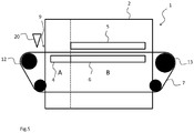
- the temperature treatment in the first temperature treatment zone A is provided by means of the first impingement temperature treatment device 4 arranged to provide impingement jets from below the moulds 8 carrying the portions of fluid, i.e. arranged to provide impingement jets at the bottoms of the moulds 8 carrying the portions of fluid. This will further limit the risk of spilling fluid from the moulds 8.
- Such an embodiment may optionally also comprise the third impingement temperature treatment device 6 discussed above
- the first and third impingement temperature treatment devices 4, 6 in this example are illustrated as two separate devices, they may be parts of a single impingement temperature treatment device.
Description
- The present invention is related to temperature treatment of fluid especially solidifying portions of fluid. Typically, but not necessarily the fluid is food in fluid form.
- An apparatus for temperature treatment, especially freezing, of fluid food products are known from for example
US 2009/0120107 . The apparatus ofUS 2009/0120107 contains a bottomless honeycomb conveyor belt and freezing of the products are realized by means of liquid nitrogen. Stripping of the frozen portions is realized by protrusions pushing through the bottomless honeycomb conveyor belt. Stripping of the frozen product is made by means of positive impressions forced into orifices of the belt pushing the ice cubes out of the belt. - In
FR 2 964 836 A1WO2009/012780 A2 an apparatus for thermal gas treatment of objects carried on an endless conveyor, in particular food items, is disclosed. The apparatus comprises: - a housing separated in two or more sections, where a first section comprises means for moving said first section in relation to a second section; an endless conveyor belt arranged inside said housing and projecting outside said housing in a first and second end, where said endless conveyor has an upper run suitable to carry the objects and a lower return run;
- two or more gas conditioning units arranged inside said housing, where the units are arranged one downstream of another along the conveyor, for directing a treated gas towards the endless conveyor; substantially gas tight partitions separating the gas conditioning units from each other, creating separate treatment zones, where said treatment zones are only connected adjacent the endless conveyor; where said housing substantially completely encloses said gas conditioning units, partitions treatment zones and the endless conveyor except for the first and second end sections.
- In
US 5 478 584 A a cooling system is disclosed. The cooling system comprises: a tunnel-type cooler housing; a first treatment zone provided in the housing for treating articles by injecting carbon dioxide into the first treatment zone toward the articles and by circulating carbon dioxide in the first treatment zone; a second treatment zone provided in the housing for further treating the articles by injecting carbon dioxide into the second treatment zone toward the articles and by circulating carbon dioxide in the second treatment zone; and a conveyor assembly for conveying the articles through the first and second treatment zones. The carbon dioxide injected into the second treatment zone impinges on the articles to a greater degree than does the carbon dioxide injected into the first treatment zone. Further, the circulation of carbon dioxide in the first and second treatment zones is conducted in a manner such that a greater degree of turbulence is created in the second treatment zone than is created in the first treatment zone. - In
CA 2 357 026 A1 , a temperature treatment apparatus for solidifying portions of fluid placed in elastic moulds is disclosed whereby said solidified portions of fluid are ejected from the moulds by heating the moulds from the bottom and then shake them. - Disadvantages with such known devices include that bottomless moulds may leak and that the freezing involves use of cryogenic liquids. Further, the stripping results in contact between the protrusions and the frozen food product, which may be undesirable.
- It is desired with an apparatus and a method for efficient solidifying portions of fluid without disadvantages of prior art.
- An object of the present invention is to provide an apparatus and a method for efficient solidifying portions of fluid without disadvantages of prior art.
- Another object of the present invention is to provide an apparatus and a method for efficient and rapid freezing of portions of fluid.
- Yet another object of the present invention is to provide an apparatus and a method for efficient and rapid freezing of portions of fluid, which does not involve cryogenic freezing.
- According to a first aspect of the present invention defined by the independent claim, there is provided a temperature treatment apparatus for solidifying portions of fluid, the apparatus comprising: an endless product conveyor belt comprising a plurality of moulds made of elastic material, each of the plurality of moulds having an open end and each of the plurality of moulds being arranged to convey a portion of fluid during solidifying of the same. The temperature treatment apparatus comprising a first impingement temperature treatment device arranged in a first temperature treatment zone and a second impingement temperature treatment device arranged in a second temperature treatment zone , wherein the first temperature treatment zone is arranged upstream the second temperature treatment zone with regard to a direction of movement of the portions of fluid during use of the apparatus, wherein the first temperature treatment zone is arranged to solidify a crust on the portions of fluid at least on a surface of the fluid closest to the open end of the moulds when the moulds comprising portions of fluid are conveyed through the first temperature treatment zone, and wherein the second temperature treatment zone is arranged to further solidify each portion of foodstuffs such that at least partly solidified portions are formed when the moulds comprising portions of fluid are conveyed through the second temperature treatment zone.
- By fluid herein is intended any product, material, matter, or composition that can flow, which comprises a liquid, and which may or may not include solid material, such as solid material in the form of small particles and up to large chunks or pieces. The fluid may, thus, for example be a fluid, a liquid suspension, a solution, or mixtures thereof. The fluid may e.g. be food in fluid form. The food in fluid form may for example be juice, milk, soup, syrup, or other aqueous solutions, suspensions or mixtures, or solutions, suspension or mixtures with oil; or mixtures thereof.
- Solidifying, as used herein, comprises converting of the fluid to solid, or any solidifying of the fluid resulting in either portions of fluid with solid properties or with higher viscosity compared to prior to the solidifying. The solidifying may be made by lowering or increasing the temperature of the portions of fluid by the impingement device. For example, in the case of lowering the temperature, the solidifying may be freezing, and in the case of increasing the temperature, the solidifying may be hardening, curing or baking of the fluid. It is not a prerequisite that the whole portion of fluid is converted to solid. It may be sufficient that the portions of fluid are made easier to handle by the solidifying, for example that they are solidified to such an extent that they can be ejected from the moulds essentially without changing their shape, and that they do not easily deform or stick together after being ejected from the moulds.
- The impingement device is an efficient means for temperature treatment. For example, in the case of lowering the temperature or freezing, the solidifying does not require cryogenic fluids interacting with the matter to be solidified, and which result in rapid solidifying.
- The impingement device having a first and a second temperature treatment zone allows for zones with different temperature treatment effects and as a result extra efficient solidifying.
- It is realized that the solidifying in the second temperature treatment zone can but must not result in a portion of foodstuff being solidified to the core. Of importance is that the portion of fluid is solidified on the surface(s), such that it can be ejected from the moulds in one piece and such that it can be efficiently handled after ejection.
- The temperature treatment effect in the first temperature treatment zone may be lower than the temperature treatment effect in the second temperature treatment zone, By the temperature treatment effect being lower in the first temperature treatment zone as compared to the second temperature treatment zone, is meant that the average pressure subjected on the surface of the portion of the foodstuff by the impingement jets is lower in the first temperature treatment zone as compared with the second temperature treatment zone.
- The moulds have bottoms. With such moulds leaking of fluid from the moulds is avoided or minimized. Further, contact between the apparatus and the fluid may be minimized.
- According to one embodiment the impingement devices may be arranged to apply impingement jets from above the endless product conveyor in the first and second temperature treatment zones. Such application of the impingement jets results in efficient and rapid solidifying of the portions of fluid as the fluid is directly hit by the impingement jets.
- According to one embodiment the temperature treatment apparatus may further have a third impingement temperature treatment device arranged to apply impingement jets from below the moulds. With such a third temperature treatment zone, solidifying of the portions of fluid may be yet more rapid. This since the portions of fluid may be subjected to impingement temperature treatment from two sides simultaneously. Further, impingement temperature treatment from the below combined with moulds having bottoms may be performed at high temperature treatment effect without risking any fluid to be blown out of the moulds.
- According to one embodiment, the endless product conveyor belt may be arranged to continuously transport the plurality of moulds conveying the portions of fluid.
- According to one embodiment, the solidify a crust may be freeze a crust, and the solidify each portion of fluid such that at least partially solidified portions are formed may be freeze each portion of foodstuffs such that at least partially frozen portions of fluid are formed.
- The apparatus further comprises a shaft about which the endless product conveyor belt is arranged to travel and wherein the shaft is arranged for ejecting the at least partially solidified portions from the plurality of moulds. Solidified portions may efficiently be ejected from the moulds with such an arrangement since the moulds are made of elastic material. Such an apparatus further benefits from not needing any other mechanical device for ejecting the solidified portions.
- Each of the plurality of moulds are arranged to deform when contacted by the shaft, whereby the at least partially solidified portions are ejected from the plurality of moulds. Thus, the solidified portions may be ejected efficiently.
- According to one embodiment, the apparatus may further comprise a drive shaft arranged to drive the endless product conveyor belt.
- According to one embodiment, the apparatus may further comprise a drive and ejection shaft arranged to drive the endless product conveyor belt and arranged for ejecting the at least partially frozen portions of foodstuffs from the plurality of moulds.
- According to one embodiment, the apparatus may further comprise a dispensing device arranged to dispense the portions of fluid in the plurality of moulds.
- According to one embodiment, the apparatus may further comprise a housing accommodating at least a part of the endless product conveyor belt and the impingement device. Such a housing may result in, for example, that a cold or hot environment efficiently can be maintained surrounding solidified portions, prior to ejection and/or after ejection.
- According to one embodiment, the apparatus comprising a housing may further comprise an additional conveyor belt, wherein the additional conveyor belt at least to a part is arranged in the housing, and wherein the additional conveyor belt is arranged to receive at least partly solidified portions ejected from the moulds, and to convey the at least partly solidified portions in a direction opposite the direction of the endless product conveyor belt. Thus, efficient further solidifying or keeping solidified of ejected solidified portions may be obtained.
- According to one embodiment, the second impingement temperature treatment device may be arranged to further solidify each portion of fluid such that a major part of each portions of fluid is solidified.
- According to a second aspect, there is provided a use of the apparatus according to the first aspect for solidifying portions of fluid.
- According to a third aspect, as defined by the independent claim, there is provided a method for solidifying portions of fluid the method comprising: dispensing fluid in elastic moulds comprised in an endless product conveyor belt for forming portions of fluid; subjecting the dispensed portions of fluid for impingement temperature treatment in a first temperature treatment zone during conveying of the endless product conveyor belt such that a crust on the portions of fluid at least on a surface of the fluid closest to an open end of the moulds is formed; and subjecting the portions of fluid for impingement temperature treatment in a second temperature treatment zone during conveying of the endless product conveyor belt such that at least partially solidified portions are formed wherein the first temperature treatment zone is arranged upstream the second temperature treatment zone with regard to a direction of movement of the portions of fluid. Such a method enables very efficient and rapid solidifying of portions of fluid, which portions can be efficiently handled. The solidified portions may be frozen portions, the method further comprises ejecting the at least partly solidified portions from the moulds by deforming the elastic moulds using a shaft about which the endless product conveyor belt is arranged to travel.
- The temperature treatment effect in the first temperature treatment zone may be lower than the temperature treatment effect in the second temperature treatment zone.
- According to one embodiment,.
- According to one embodiment, the method may further comprise further solidifying the ejected at least partly solidified portions using an additional conveyor belt arranged to travel in opposite direction as compared with the endless product conveyor belt. The solidifying may be freezing.
- With regards to the second and third aspects of the invention, the discussions and embodiments of the first aspect of the invention are directly applicable whereby references to these discussions and embodiments are made.
- These and other aspects of the present invention will now be described in more detail, with reference to the appended drawings showing embodiments of the invention wherein like reference numerals refer to like elements throughout unless stated otherwise.
-
Fig. 1 is a schematic illustration of a temperature treatment apparatus according to one embodiment. -
Fig. 2 is a schematic illustration of a part of a temperature treatment apparatus according to one embodiment. -
Fig. 3 is a schematic illustration of a temperature treatment apparatus according to one embodiment. -
Fig. 4 is a schematic illustration of a method according to one embodiment. -
Fig. 5 is a schematic illustration of a temperature treatment apparatus according to one embodiment. - The following detailed descriptions of embodiments of the invention are included as examples of embodiments of the invention to improve the understanding of the invention and should not in any way be interpreted as limiting the scope of the invention.
- With reference to
figure 1 , an embodiment of a temperature treatment apparatus will now be discussed. Theapparatus 1 is partly accommodated within ahousing 2. - The
temperature treatment apparatus 1 comprises two different temperature treatment zones A, B. In a first temperature treatment zone A a first impingementtemperature treatment device 4 is arranged. In a second temperature treatment zone B a second impingementtemperature treatment device 5 is arranged. Although the first and second impingementtemperature treatment devices - The
apparatus 1 further has anendless conveyor belt 7 partly accommodated by thehousing 2. The conveyor belt has a plurality ofmoulds 8, not illustrated infigure 1 but infigure 2 . Themoulds 8 are, in this example, filled with fluid by means of asuitable dispensing device 20 arranged to dispense the portions of fluid in the plurality of moulds. The direction of movement of theconveyor belt 7 are illustrated byarrow 10, and it will be understood from viewingfigure 1 that themoulds 8 filled with fluid are conveyed from left to right on the upper part of theconveyor belt 7 through the housing and passing the temperature treatment zones A, B, after which they will leave thehousing 7 in the area indicated byarrow 11. - In the in
Figure 1 shown embodiment, the first and second impingementtemperature treatment devices endless conveyor belt 7. Hence, the first and second impingementtemperature treatment device temperature treatment devices temperature treatment devices Figure 5 . - The temperature treatment effect of the first temperature treatment zone A is lower than that of the second temperature treatment zone B, which in this example is realized by a longer distance between the portions of fluid and the first impingement
temperature treatment device 4, compared to the second impingementtemperature treatment device 5. Hence, the lower temperature treatment effect in the first temperature treatment zone A is provided for by a lower pressure of the impingement jets impinging the fluid in the moulds. A lower pressure of the impingement jets may also be realized, for example, by a fan with lower effect for the first impingement temperature treatment device4. Any suitable way for obtaining an average pressure subjected on the surface of the portion of the fluid by the impingement jets being lower in the first temperature treatment zone A as compared with the second temperature treatment zone B are intended, and any suitable way of obtaining suitable temperature treatment effects in the temperature treatment zones A, B are intended to be covered. For example, the impingementtemperature treatment devices - Efficient impingement temperature treatment in the first temperature treatment zone A will rapidly solidify a crust on the surface of the fluid without risking the fluid to spill out of the container caused by too forceful impingement jets. The solidifying may, for example, be freezing of the fluid, in which case impingement freezing is used, or, for example, heating of the fluid, such as baking of a fluid baking mixture, in which case impingement heating is used. The portions of fluid leaving the first temperature treatment zone A and entering the second temperature treatment zone B, thus, have a solidified crust on the surface, which makes it possible to subject the portions of fluid to impingement temperature treatment with the higher temperature treatment effect in the second temperature treatment zone. Thus, the apparatus enables very rapid and efficient solidifying of portions of fluid.
- The temperature treatment effect of the first impingement
temperature treatment device 4 should be selected such that the impingements jets do not blow the fluid out of the moulds but still with such a temperature treatment effect that the fluid is solidified at least on the surface close to the opening of the moulds. It is realized that in the case of low temperature treatment, with impingement freezing, and if the fluid have high water content a crust may be frozen on the portions of fluid. If the fluid have lower aqueous content and comprises for example fat, it may not be that a crust is frozen on the surface, but rather that the fluid is solidified by the freezing. Important is that the surfaces of the fluid in the area of the open end of the moulds are solidified such that when entering the second temperature treatment zone B, the temperature treatment effect of the second impingementtemperature treatment device 5 can be selected higher than for the first impingementtemperature treatment device 4 since the solidified surface prevents any spilling blowing away of the fluid from themoulds 8. Thus, the combination of the first and second temperature treatment zones A, B makes it possible to obtain very rapid temperature treatment still with minimized risks of spilling fluid from themoulds 8. - As the portions of fluid are passing the first and the second temperature treatment zones A, B, they may also be subjected to impingement temperature treatment from below via a third impingement
temperature treatment device 6. The temperature treatment effect of the third impingementtemperature treatment device 6 can be higher than for the first impingementtemperature treatment device 4. Moreover, The temperature treatment effect of the third impingementtemperature treatment device 6 can be higher than for the second impingementtemperature treatment device 5. This since the conveyor belt and the bottoms of the moulds in this case prevents blowing away of fluid from themoulds 8. It is to be understood that according to this embodiment the third impingementtemperature treatment device 6 is optional. - After having passed the second temperature treatment zone B, the, portions of fluid have been subjected to such temperature treatment that they are solidified on all outer surfaces. Such portions of fluid can be efficiently ejected from the
moulds 8 and they may be efficiently further treated, such as packed, transported or further solidified. Thus, it is not necessary that the portions are solidified throughout their volume when being ejected. - Two shafts are acting in supporting and driving the
conveyor belt 7. Adrive shaft 12 may act in driving theconveyor belt 7. Afirst shaft 13 may be arranged for ejecting the at least partly solidified portions from the plurality of moulds, as a result of the moulds being made from flexible material and thefirst shaft 13 pressing against the moulds as they pass. The ejected portions of solidified fluid may be collected by suitable means (not illustrated). It is realized that the ejection of the solidified portions alternatively could take place by action of thedrive shaft 12, the portions of solidified foodstuffs thus would benefit from further temperature treatment in the housing. Ejected portions of solidified fluid may be stored after ejection inside the housing for further solidification or for maintaining a low or high temperature. - According to one embodiment, the temperature treatment may be cooling, such as freezing.
- According to one embodiment, the temperature treatment may be heating.
- According to one embodiment, the impingement temperature treatment may be impingement freezing.
- According to one embodiment, the impingement temperature treatment may be impingement heating.
-
Figure 2 illustrates a part of aconveyor belt 7. Theconveyor belt 7 comprises a plurality ofmoulds 8, in this embodiment shaped as semi spheres. It is realized that themoulds 8 could have any other suitable shape, such as for example cylindrical or cubic. -
Figure 3 illustrates anapparatus 1 as discussed above with reference tofigure 1 , with a difference that according to this embodiment, theapparatus 1 further comprises anadditional conveyor belt 24 arranged to receive at least partly solidified portions ejected from themoulds 8, and to convey the solidified portions in a direction opposite the direction of theconveyor belt 7, as indicated byarrow 26. - With reference to
figure 4 , an embodiment of a method for solidifying portions of fluid is illustrated. The method comprises: -
Dispensing 30 fluid in elastic moulds comprised in an endless product conveyor belt for forming portions of fluid; - subjecting 32 the dispensed portions of fluid for impingement temperature treatment in a first temperature treatment zone A during conveying of the endless product conveyor belt such that a crust on the portions of fluid at least on a surface of the fluid closest to an open end of the moulds is formed; and
- subjecting 34 the portions of fluid for impingement temperature treatment in a second temperature treatment zone B during conveying of the endless product conveyor belt such that at least partially solidified portions are formed,
- wherein the temperature treatment effect in the first temperature treatment zone is lower than the temperature treatment effect in the second temperature treatment zone and wherein the first temperature treatment zone is arranged upstream the second temperature treatment zone with regard to a direction of movement of the portions of fluid.
- The person skilled in the art realizes that the present invention by no means is limited to the preferred embodiments described above. On the contrary, many modifications and variations are possible within the scope of the appended claims. For example, the apparatus may be fully accommodated within the
housing 2. - According to one embodiment of the present invention, see
figure 5 , the temperature treatment in the first temperature treatment zone A is provided by means of the first impingementtemperature treatment device 4 arranged to provide impingement jets from below themoulds 8 carrying the portions of fluid, i.e. arranged to provide impingement jets at the bottoms of themoulds 8 carrying the portions of fluid. This will further limit the risk of spilling fluid from themoulds 8. Such an embodiment may optionally also comprise the third impingementtemperature treatment device 6 discussed above Although the first and third impingementtemperature treatment devices - Additionally, variations to the disclosed embodiments can be understood and effected by the skilled person in practicing the claimed invention, from a study of the drawings, the disclosure, and the appended claims. In the claims, the word "comprising" does not exclude other elements or steps, and the indefinite article "a" or "an" does not exclude a plurality.
Claims (13)
- A temperature treatment apparatus for solidifying portions of fluid, the apparatus comprising:an endless product conveyor belt (7) comprising a plurality of moulds (8) made of elastic material, each of the plurality of moulds (8) having an open end, through which a fluid is dispensed, and a bottom, each of the plurality of moulds (8) being arranged to convey a portion of fluid during solidifying of the same,a shaft (12, 13) about which the endless product conveyor belt (7) is arranged to travel and wherein the shaft (12, 13) is arranged to bear against the mould for ejecting the at least partially solidified portions from the plurality of moulds (8), the apparatus being characterized bya first impingement temperature treatment device (4) arranged in a first temperature treatment zone (A),a second impingement temperature treatment device (5) arranged in a second temperature treatment zone (B),wherein the first temperature treatment zone (A) is arranged upstream the second temperature treatment zone (B) with regard to a direction of movement of the portions of fluid during use of the apparatus,wherein the first temperature treatment zone (A) is arranged to solidify a crust on the portions of fluid at least on a surface of the fluid closest to the open end of the moulds (8) when the moulds (8) comprising portions of fluid are conveyed through the first temperature treatment zone (A), andwherein the second temperature treatment zone (B) is arranged to further solidify each portion of fluid such that at least partly solidified portions are formed when the moulds (8) comprising portions of fluid are conveyed through the second temperature treatment zone (B),and wherein each of the plurality of moulds (8) is arranged to deform when contacted by the shaft (12, 13), whereby the at least partially solidified portions are ejected from the plurality of moulds (8).
- The apparatus according to claim 1, wherein the temperature treatment effect in the first temperature treatment zone (A) is lower than the temperature treatment effect in the second temperature treatment zone (B).
- The apparatus according to claim 1 or 2, wherein the impingement temperature treatment devices (4, 5) are arranged to apply impingement jets from above the endless product conveyor in the first and second temperature treatment zones (A, B).
- The apparatus according to claim 3, wherein the moulds (8) have bottoms, and the apparatus further comprises a third impingement temperature treatment device (6) arranged to apply impingement jets from below the moulds (8).
- The apparatus according to anyone of claims 1 to 4, wherein the endless product conveyor belt (7) is arranged to continuously transport the plurality of moulds (8) conveying the portions of fluid.
- The apparatus according to anyone of claims 1 to 5,wherein a crust is formed by freezing, andwherein each portion of the fluid is at least partly solidified by freezing such that frozen portions are formed.
- The apparatus according to anyone of claims 1 to 6, further comprising a drive shaft (12, 13) arranged to drive the endless product conveyor belt (7).
- The apparatus according to anyone of claims 1 to 7, further comprising a dispensing device (20) arranged to dispense the portions of fluid in the plurality of moulds (8).
- The apparatus according to anyone of the previous claims 1 to 8 further comprising a housing (2) accommodating at least a part of the endless product conveyor belt (7) and the impingement temperature treatment devices (4, 5).
- The apparatus according to claim 9 further comprising an additional conveyor belt (24), wherein the additional conveyor belt (24) at least to a part is arranged in the housing (2), and wherein the additional conveyor belt (24) is arranged to receive at least partly solidified portions ejected from the moulds (8), and to convey the at least partly solidified portions in a direction (26) opposite the direction (10) of the endless product conveyor belt (7).
- The apparatus according to anyone of claims 1 to 10, wherein the second impingement temperature treatment device (5) is arranged to further solidify each portion of fluid such that a major part of each portions of fluid is solidified.
- A use of the apparatus according to anyone of claims 1 to 11 for solidifying portions of fluid.
- A method for solidifying portions of fluid the method comprising:dispensing (30) fluid in elastic moulds (8), having an open end, through which a fluid is dispensed, and a bottom, comprised in an endless product conveyor belt (7) for forming portions of the received fluid;arranging a shaft (12, 13) about which the endless product conveyor belt (7) travels to bear against the mould for ejecting the at least partially solidified portions from the plurality of moulds (8), the method being characterized bysubjecting (32) the dispensed portions of fluid for impingement temperature treatment in a first temperature treatment zone (A) during conveying of the endless product conveyor belt (7) such that a crust on the top portions of fluid at least on a surface of the fluid closest to the open top of the moulds (8) is formed; andsubjecting (34) the fluid for impingement temperature treatment in a second temperature treatment zone (B) during conveying of the endless product conveyor belt (7) such that at least partially solidified portions are formed,wherein the first temperature treatment zone (A) is arranged upstream the second temperature treatment zone (B) with regard to a direction of movement of the portions of fluid,and wherein each of the plurality of moulds (8) is arranged to deform when contacted by the shaft (12, 13), whereby the at least partially solidified portions are ejected from the plurality of moulds (8).
Priority Applications (5)
| Application Number | Priority Date | Filing Date | Title |
|---|---|---|---|
| DK14172406.2T DK2955466T3 (en) | 2014-06-13 | 2014-06-13 | TEMPERATURE TREATMENT DEVICE AND PROCEDURE FOR STRENGTHENING LIQUID PORTIONS |
| EP14172406.2A EP2955466B1 (en) | 2014-06-13 | 2014-06-13 | Temperature treatment apparatus and method for solidifying portions of fluid |
| CN201580030625.5A CN106461307A (en) | 2014-06-13 | 2015-06-12 | Temperature treatment apparatus and method for solidifying portions of fluid |
| US15/318,653 US11026440B2 (en) | 2014-06-13 | 2015-06-12 | Temperature treatment apparatus and method for solidifying portions of fluid |
| PCT/EP2015/063192 WO2015189398A1 (en) | 2014-06-13 | 2015-06-12 | Temperature treatment apparatus and method for solidifying portions of fluid |
Applications Claiming Priority (1)
| Application Number | Priority Date | Filing Date | Title |
|---|---|---|---|
| EP14172406.2A EP2955466B1 (en) | 2014-06-13 | 2014-06-13 | Temperature treatment apparatus and method for solidifying portions of fluid |
Publications (2)
| Publication Number | Publication Date |
|---|---|
| EP2955466A1 EP2955466A1 (en) | 2015-12-16 |
| EP2955466B1 true EP2955466B1 (en) | 2020-02-12 |
Family
ID=51059266
Family Applications (1)
| Application Number | Title | Priority Date | Filing Date |
|---|---|---|---|
| EP14172406.2A Active EP2955466B1 (en) | 2014-06-13 | 2014-06-13 | Temperature treatment apparatus and method for solidifying portions of fluid |
Country Status (5)
| Country | Link |
|---|---|
| US (1) | US11026440B2 (en) |
| EP (1) | EP2955466B1 (en) |
| CN (1) | CN106461307A (en) |
| DK (1) | DK2955466T3 (en) |
| WO (1) | WO2015189398A1 (en) |
Cited By (1)
| Publication number | Priority date | Publication date | Assignee | Title |
|---|---|---|---|---|
| DE102021002813A1 (en) | 2021-06-01 | 2022-12-01 | Messer France S.A.S. | Process and apparatus for making frozen products |
Families Citing this family (3)
| Publication number | Priority date | Publication date | Assignee | Title |
|---|---|---|---|---|
| DK2955466T3 (en) | 2014-06-13 | 2020-03-16 | John Bean Technologies Ab | TEMPERATURE TREATMENT DEVICE AND PROCEDURE FOR STRENGTHENING LIQUID PORTIONS |
| EP3422859A4 (en) * | 2016-03-01 | 2019-09-04 | The Hillshire Brands Company | System and method for producing formed meat patties |
| CN111227287A (en) * | 2020-01-10 | 2020-06-05 | 王帅峰 | Conveying type block food processing device capable of achieving rapid demoulding |
Citations (1)
| Publication number | Priority date | Publication date | Assignee | Title |
|---|---|---|---|---|
| WO2000038533A1 (en) * | 1998-12-29 | 2000-07-06 | Societe Des Produits Nestle S.A. | Iced dessert and method for making same |
Family Cites Families (44)
| Publication number | Priority date | Publication date | Assignee | Title |
|---|---|---|---|---|
| US993321A (en) * | 1908-03-31 | 1911-05-23 | George David Cullum Coddington | Machine for molding sealing-wax. |
| US2021047A (en) * | 1933-06-12 | 1935-11-12 | Gen Motors Corp | Endless freezing container |
| US2080103A (en) * | 1934-04-10 | 1937-05-11 | Processes Inc Z | Method and apparatus for refrigerating food products |
| FR1211534A (en) * | 1958-08-14 | 1960-03-16 | Wilhelm Schmitz Scholl | Device for manufacturing filled, moldable, injectable bodies, in particular filled chocolate moldings |
| US3427820A (en) * | 1966-11-14 | 1969-02-18 | Reliquifier Corp Of America | Cryogenic flash freezing machines |
| DK122346B (en) * | 1969-02-27 | 1972-02-21 | Gram Brdr As | Contact freezer with movable freezer elements. |
| GB1531461A (en) * | 1975-02-10 | 1978-11-08 | Boc International Ltd | Method and apparatus for cooling or freezing articles |
| US4481782A (en) * | 1983-01-25 | 1984-11-13 | The Boc Group, Inc. | Methods and apparatus for refrigerating products |
| US4802839A (en) * | 1986-03-20 | 1989-02-07 | Yoshiyuki Corporation | Apparatus for producing cast products |
| GB2225629B (en) * | 1988-12-23 | 1992-11-18 | Nissin Gourmet Beef Co Ltd | Continuous quick freezing method for food |
| FR2686403B1 (en) * | 1992-01-21 | 2001-02-09 | Air Liquide | FREEZING PROCESS AND DEVICE. |
| GB9214427D0 (en) * | 1992-07-07 | 1992-08-19 | Air Prod & Chem | Method and apparatus for freezing |
| US5460015A (en) * | 1994-04-28 | 1995-10-24 | Liquid Carbonic Corporation | Freezer with imperforate conveyor belt |
| US5444985A (en) * | 1994-05-13 | 1995-08-29 | Liquid Carbonic Corporation | Cryogenic tunnel freezer |
| US5478584A (en) * | 1995-02-15 | 1995-12-26 | Tyson Holding Company | Freezing system |
| SE504928C2 (en) * | 1996-07-30 | 1997-05-26 | Frigoscandia Equipment Ab | Food product freezing apparatus |
| DK0973410T3 (en) | 1997-03-04 | 2002-07-29 | Nestle Sa | Ice cream confectionery product and method, apparatus and mold for making it |
| SE9701550L (en) | 1997-04-25 | 1998-03-09 | Frigoscandia Equipment Ab | Methods and apparatus for surface freezing |
| US5813237A (en) * | 1997-06-27 | 1998-09-29 | The Boc Group, Inc. | Cryogenic apparatus and method for spraying a cryogen incorporating generation of two phase flow |
| US5966962A (en) * | 1998-05-08 | 1999-10-19 | Thermal Products, Inc. | Modular hydration and freezing plant for flexible refrigerant media |
| JP3641772B2 (en) | 1997-11-28 | 2005-04-27 | 株式会社前川製作所 | Continuously shaped cooling and solidification equipment for liquid work |
| FR2783311B1 (en) * | 1998-09-14 | 2000-10-06 | Air Liquide | METHOD AND APPARATUS FOR FREEZING PRODUCTS ONLINE |
| ES2253148T3 (en) * | 2000-03-16 | 2006-06-01 | Aga Aktiebolag | FOOD REFRIGERATOR AND PROCEDURE FOR COOLING FOOD. |
| GB2380247A (en) * | 2001-09-28 | 2003-04-02 | Air Prod & Chem | Tunnel freezer belt |
| US7008658B2 (en) * | 2002-05-29 | 2006-03-07 | The Boc Group, Inc. | Apparatus and method for providing treatment to a continuous supply of food product by impingement |
| FR2882810B1 (en) | 2005-03-02 | 2007-04-27 | Air Liquide | ICE GENERATOR OF LIQUID OR PASTY PRODUCTS |
| US7197883B2 (en) * | 2005-05-06 | 2007-04-03 | Praxair Technology, Inc. | Cooling or heating with multi-pass fluid flow |
| ITTO20070452A1 (en) * | 2007-06-22 | 2008-12-23 | Soremartec Sa | SYSTEM FOR THE FLEXIBLE PRODUCTION OF A PLURALITY OF TYPES OF FOOD-MOLDED PRODUCTS, IN PARTICULAR CHOCOLATE AND SIMILAR PRODUCTS |
| WO2009012780A2 (en) * | 2007-07-25 | 2009-01-29 | Dantech Food Systems Pte Ltd. | Apparatus for thermal gas treatment |
| US7829131B2 (en) * | 2007-08-21 | 2010-11-09 | Lion Rock Holdings, Llc | Package for molded food product and method |
| EP2216613A1 (en) * | 2009-02-09 | 2010-08-11 | Dometic Sweden AB | Ice maker and method of producing pieces of ice |
| US20110311700A1 (en) * | 2009-12-11 | 2011-12-22 | Paul Cyrus Shah | System and method of chilling a food product proximate to and in a food processing device |
| US20140230460A1 (en) * | 2009-12-22 | 2014-08-21 | Michael D. Newman | Heat flux freezer control apparatus and method |
| US20120047916A1 (en) * | 2010-08-30 | 2012-03-01 | Jos Wijlens | Thermoformed film belt freezer |
| FR2964836A1 (en) * | 2010-09-20 | 2012-03-23 | Saint Jean | Device for cooling food product e.g. sauce for its solidification, comprises enclosure, unit for producing cold in interior of enclosure, station for supplying product to liquid/pasty state, and unit for conveying product in enclosure |
| US10448660B2 (en) * | 2011-10-03 | 2019-10-22 | Kerry Luxembourg S.à.r.l. | Metering the disposition of a food product into cavities forming a pellet |
| US20130125576A1 (en) * | 2011-11-17 | 2013-05-23 | Michael D. Newman | Freezer apparatus |
| US9648898B2 (en) * | 2012-09-13 | 2017-05-16 | Kerry Luxembourg S.à.r.l. | Metering the disposition of a food product into cavities forming a pellet |
| ITMI20131941A1 (en) * | 2013-11-21 | 2015-05-22 | Previero Sas | APPARATUS AND METHOD TO SEPARATE MATERIALS OF VARIOUS TYPE |
| MX2016009169A (en) * | 2014-01-16 | 2017-03-08 | Praxair Technology Inc | Apparatus and method for chilling or freezing. |
| DK2955466T3 (en) * | 2014-06-13 | 2020-03-16 | John Bean Technologies Ab | TEMPERATURE TREATMENT DEVICE AND PROCEDURE FOR STRENGTHENING LIQUID PORTIONS |
| US20180058744A1 (en) * | 2016-09-01 | 2018-03-01 | Michael D. Newman | Method and apparatus for impingement freezing of irregularly shaped products |
| US20180103661A1 (en) * | 2016-10-17 | 2018-04-19 | Michael D. Newman | Apparatus and method for freezer gas control |
| US11337551B2 (en) * | 2018-02-07 | 2022-05-24 | John Bean Technologies Ab | Heating element assembly for cooking apparatus |
-
2014
- 2014-06-13 DK DK14172406.2T patent/DK2955466T3/en active
- 2014-06-13 EP EP14172406.2A patent/EP2955466B1/en active Active
-
2015
- 2015-06-12 US US15/318,653 patent/US11026440B2/en active Active
- 2015-06-12 WO PCT/EP2015/063192 patent/WO2015189398A1/en active Application Filing
- 2015-06-12 CN CN201580030625.5A patent/CN106461307A/en active Pending
Patent Citations (1)
| Publication number | Priority date | Publication date | Assignee | Title |
|---|---|---|---|---|
| WO2000038533A1 (en) * | 1998-12-29 | 2000-07-06 | Societe Des Produits Nestle S.A. | Iced dessert and method for making same |
Cited By (2)
| Publication number | Priority date | Publication date | Assignee | Title |
|---|---|---|---|---|
| DE102021002813A1 (en) | 2021-06-01 | 2022-12-01 | Messer France S.A.S. | Process and apparatus for making frozen products |
| DE102021002813B4 (en) | 2021-06-01 | 2023-03-23 | Messer France S.A.S. | Process and apparatus for making frozen products |
Also Published As
| Publication number | Publication date |
|---|---|
| US11026440B2 (en) | 2021-06-08 |
| US20170127706A1 (en) | 2017-05-11 |
| DK2955466T3 (en) | 2020-03-16 |
| WO2015189398A1 (en) | 2015-12-17 |
| EP2955466A1 (en) | 2015-12-16 |
| CN106461307A (en) | 2017-02-22 |
Similar Documents
| Publication | Publication Date | Title |
|---|---|---|
| EP2955466B1 (en) | Temperature treatment apparatus and method for solidifying portions of fluid | |
| CN1101140C (en) | Method and apparatus for moulding of iced confectionery articles | |
| CA1300385C (en) | Cryogenic combination tunnel freezer | |
| US2282187A (en) | Process of pasteurizing liquids in containers | |
| EP2447633B1 (en) | Continuous food freezing device and continuous food freezing method | |
| WO2003091640A1 (en) | Apparatus and method for producing ice container using ice powders | |
| US20170051962A1 (en) | Device and a method for making ice cubes and a metering device for ice cubes | |
| CA2144930A1 (en) | Freezing system for frangible food products | |
| KR102608525B1 (en) | Manufacturing and storage of free-flowing refrigerated secondary products | |
| US1817890A (en) | Refrigerating apparatus and method of refrigerating food products | |
| CN108885043B (en) | Device for metering carbon dioxide snow | |
| TW201936060A (en) | Frozen confectionary material molding device and frozen confectionary material molding method | |
| JPS6125351B2 (en) | ||
| BE1027366B1 (en) | FREEZER TUNNEL FOR FREEZING INDIVIDUAL PORTIONS OF FOOD | |
| US2116738A (en) | Method and apparatus for freezing vegetables and fruits | |
| US1894813A (en) | Means and method for chilling and freezing foodstuffs | |
| US20200173706A1 (en) | Efficient clear ice cube production | |
| CN102802430A (en) | Manufacturing method and apparatus for popping candy | |
| CN106182901A (en) | A kind of plastic packing box continuous processing equipment | |
| US1455156A (en) | Apparatus for refrigeration | |
| US3111011A (en) | Apparatus for preserving liquids by freezing | |
| US20130152801A1 (en) | Device for heat-processing co-extruded sausages | |
| FI68756B (en) | METHODS OF TRANSMISSION FOR THE CONSTRUCTION OF DJUPFRYST CONFECT | |
| TWI581718B (en) | Method for manufacturing twice-removing ice, device of molding twice-removing ice and ice merchandise thereof | |
| US1969418A (en) | Apparatus for quick freezing of articles |
Legal Events
| Date | Code | Title | Description |
|---|---|---|---|
| PUAI | Public reference made under article 153(3) epc to a published international application that has entered the european phase |
Free format text: ORIGINAL CODE: 0009012 |
|
| 17P | Request for examination filed |
Effective date: 20151023 |
|
| AK | Designated contracting states |
Kind code of ref document: A1 Designated state(s): AL AT BE BG CH CY CZ DE DK EE ES FI FR GB GR HR HU IE IS IT LI LT LU LV MC MK MT NL NO PL PT RO RS SE SI SK SM TR |
|
| AX | Request for extension of the european patent |
Extension state: BA ME |
|
| STAA | Information on the status of an ep patent application or granted ep patent |
Free format text: STATUS: EXAMINATION IS IN PROGRESS |
|
| 17Q | First examination report despatched |
Effective date: 20181017 |
|
| GRAP | Despatch of communication of intention to grant a patent |
Free format text: ORIGINAL CODE: EPIDOSNIGR1 |
|
| STAA | Information on the status of an ep patent application or granted ep patent |
Free format text: STATUS: GRANT OF PATENT IS INTENDED |
|
| RIC1 | Information provided on ipc code assigned before grant |
Ipc: A23L 3/36 20060101ALI20190918BHEP Ipc: A23P 30/10 20160101ALI20190918BHEP Ipc: F25D 25/04 20060101ALI20190918BHEP Ipc: F25D 13/06 20060101AFI20190918BHEP |
|
| INTG | Intention to grant announced |
Effective date: 20191002 |
|
| GRAS | Grant fee paid |
Free format text: ORIGINAL CODE: EPIDOSNIGR3 |
|
| GRAA | (expected) grant |
Free format text: ORIGINAL CODE: 0009210 |
|
| STAA | Information on the status of an ep patent application or granted ep patent |
Free format text: STATUS: THE PATENT HAS BEEN GRANTED |
|
| AK | Designated contracting states |
Kind code of ref document: B1 Designated state(s): AL AT BE BG CH CY CZ DE DK EE ES FI FR GB GR HR HU IE IS IT LI LT LU LV MC MK MT NL NO PL PT RO RS SE SI SK SM TR |
|
| REG | Reference to a national code |
Ref country code: GB Ref legal event code: FG4D |
|
| REG | Reference to a national code |
Ref country code: CH Ref legal event code: EP |
|
| REG | Reference to a national code |
Ref country code: AT Ref legal event code: REF Ref document number: 1232657 Country of ref document: AT Kind code of ref document: T Effective date: 20200215 |
|
| REG | Reference to a national code |
Ref country code: IE Ref legal event code: FG4D |
|
| REG | Reference to a national code |
Ref country code: DE Ref legal event code: R096 Ref document number: 602014060808 Country of ref document: DE |
|
| REG | Reference to a national code |
Ref country code: DK Ref legal event code: T3 Effective date: 20200311 |
|
| REG | Reference to a national code |
Ref country code: NL Ref legal event code: FP |
|
| PG25 | Lapsed in a contracting state [announced via postgrant information from national office to epo] |
Ref country code: RS Free format text: LAPSE BECAUSE OF FAILURE TO SUBMIT A TRANSLATION OF THE DESCRIPTION OR TO PAY THE FEE WITHIN THE PRESCRIBED TIME-LIMIT Effective date: 20200212 Ref country code: FI Free format text: LAPSE BECAUSE OF FAILURE TO SUBMIT A TRANSLATION OF THE DESCRIPTION OR TO PAY THE FEE WITHIN THE PRESCRIBED TIME-LIMIT Effective date: 20200212 Ref country code: NO Free format text: LAPSE BECAUSE OF FAILURE TO SUBMIT A TRANSLATION OF THE DESCRIPTION OR TO PAY THE FEE WITHIN THE PRESCRIBED TIME-LIMIT Effective date: 20200512 |
|
| REG | Reference to a national code |
Ref country code: LT Ref legal event code: MG4D |
|
| PG25 | Lapsed in a contracting state [announced via postgrant information from national office to epo] |
Ref country code: LV Free format text: LAPSE BECAUSE OF FAILURE TO SUBMIT A TRANSLATION OF THE DESCRIPTION OR TO PAY THE FEE WITHIN THE PRESCRIBED TIME-LIMIT Effective date: 20200212 Ref country code: SE Free format text: LAPSE BECAUSE OF FAILURE TO SUBMIT A TRANSLATION OF THE DESCRIPTION OR TO PAY THE FEE WITHIN THE PRESCRIBED TIME-LIMIT Effective date: 20200212 Ref country code: BG Free format text: LAPSE BECAUSE OF FAILURE TO SUBMIT A TRANSLATION OF THE DESCRIPTION OR TO PAY THE FEE WITHIN THE PRESCRIBED TIME-LIMIT Effective date: 20200512 Ref country code: GR Free format text: LAPSE BECAUSE OF FAILURE TO SUBMIT A TRANSLATION OF THE DESCRIPTION OR TO PAY THE FEE WITHIN THE PRESCRIBED TIME-LIMIT Effective date: 20200513 Ref country code: IS Free format text: LAPSE BECAUSE OF FAILURE TO SUBMIT A TRANSLATION OF THE DESCRIPTION OR TO PAY THE FEE WITHIN THE PRESCRIBED TIME-LIMIT Effective date: 20200612 Ref country code: HR Free format text: LAPSE BECAUSE OF FAILURE TO SUBMIT A TRANSLATION OF THE DESCRIPTION OR TO PAY THE FEE WITHIN THE PRESCRIBED TIME-LIMIT Effective date: 20200212 |
|
| PG25 | Lapsed in a contracting state [announced via postgrant information from national office to epo] |
Ref country code: SM Free format text: LAPSE BECAUSE OF FAILURE TO SUBMIT A TRANSLATION OF THE DESCRIPTION OR TO PAY THE FEE WITHIN THE PRESCRIBED TIME-LIMIT Effective date: 20200212 Ref country code: LT Free format text: LAPSE BECAUSE OF FAILURE TO SUBMIT A TRANSLATION OF THE DESCRIPTION OR TO PAY THE FEE WITHIN THE PRESCRIBED TIME-LIMIT Effective date: 20200212 Ref country code: EE Free format text: LAPSE BECAUSE OF FAILURE TO SUBMIT A TRANSLATION OF THE DESCRIPTION OR TO PAY THE FEE WITHIN THE PRESCRIBED TIME-LIMIT Effective date: 20200212 Ref country code: SK Free format text: LAPSE BECAUSE OF FAILURE TO SUBMIT A TRANSLATION OF THE DESCRIPTION OR TO PAY THE FEE WITHIN THE PRESCRIBED TIME-LIMIT Effective date: 20200212 Ref country code: ES Free format text: LAPSE BECAUSE OF FAILURE TO SUBMIT A TRANSLATION OF THE DESCRIPTION OR TO PAY THE FEE WITHIN THE PRESCRIBED TIME-LIMIT Effective date: 20200212 Ref country code: PT Free format text: LAPSE BECAUSE OF FAILURE TO SUBMIT A TRANSLATION OF THE DESCRIPTION OR TO PAY THE FEE WITHIN THE PRESCRIBED TIME-LIMIT Effective date: 20200705 Ref country code: CZ Free format text: LAPSE BECAUSE OF FAILURE TO SUBMIT A TRANSLATION OF THE DESCRIPTION OR TO PAY THE FEE WITHIN THE PRESCRIBED TIME-LIMIT Effective date: 20200212 Ref country code: RO Free format text: LAPSE BECAUSE OF FAILURE TO SUBMIT A TRANSLATION OF THE DESCRIPTION OR TO PAY THE FEE WITHIN THE PRESCRIBED TIME-LIMIT Effective date: 20200212 |
|
| REG | Reference to a national code |
Ref country code: DE Ref legal event code: R097 Ref document number: 602014060808 Country of ref document: DE |
|
| REG | Reference to a national code |
Ref country code: AT Ref legal event code: MK05 Ref document number: 1232657 Country of ref document: AT Kind code of ref document: T Effective date: 20200212 |
|
| PLBE | No opposition filed within time limit |
Free format text: ORIGINAL CODE: 0009261 |
|
| STAA | Information on the status of an ep patent application or granted ep patent |
Free format text: STATUS: NO OPPOSITION FILED WITHIN TIME LIMIT |
|
| 26N | No opposition filed |
Effective date: 20201113 |
|
| PG25 | Lapsed in a contracting state [announced via postgrant information from national office to epo] |
Ref country code: MC Free format text: LAPSE BECAUSE OF FAILURE TO SUBMIT A TRANSLATION OF THE DESCRIPTION OR TO PAY THE FEE WITHIN THE PRESCRIBED TIME-LIMIT Effective date: 20200212 Ref country code: IT Free format text: LAPSE BECAUSE OF FAILURE TO SUBMIT A TRANSLATION OF THE DESCRIPTION OR TO PAY THE FEE WITHIN THE PRESCRIBED TIME-LIMIT Effective date: 20200212 Ref country code: AT Free format text: LAPSE BECAUSE OF FAILURE TO SUBMIT A TRANSLATION OF THE DESCRIPTION OR TO PAY THE FEE WITHIN THE PRESCRIBED TIME-LIMIT Effective date: 20200212 |
|
| REG | Reference to a national code |
Ref country code: CH Ref legal event code: PL |
|
| PG25 | Lapsed in a contracting state [announced via postgrant information from national office to epo] |
Ref country code: SI Free format text: LAPSE BECAUSE OF FAILURE TO SUBMIT A TRANSLATION OF THE DESCRIPTION OR TO PAY THE FEE WITHIN THE PRESCRIBED TIME-LIMIT Effective date: 20200212 Ref country code: PL Free format text: LAPSE BECAUSE OF FAILURE TO SUBMIT A TRANSLATION OF THE DESCRIPTION OR TO PAY THE FEE WITHIN THE PRESCRIBED TIME-LIMIT Effective date: 20200212 |
|
| GBPC | Gb: european patent ceased through non-payment of renewal fee |
Effective date: 20200613 |
|
| PG25 | Lapsed in a contracting state [announced via postgrant information from national office to epo] |
Ref country code: LU Free format text: LAPSE BECAUSE OF NON-PAYMENT OF DUE FEES Effective date: 20200613 |
|
| REG | Reference to a national code |
Ref country code: BE Ref legal event code: MM Effective date: 20200630 |
|
| PG25 | Lapsed in a contracting state [announced via postgrant information from national office to epo] |
Ref country code: CH Free format text: LAPSE BECAUSE OF NON-PAYMENT OF DUE FEES Effective date: 20200630 Ref country code: LI Free format text: LAPSE BECAUSE OF NON-PAYMENT OF DUE FEES Effective date: 20200630 Ref country code: IE Free format text: LAPSE BECAUSE OF NON-PAYMENT OF DUE FEES Effective date: 20200613 Ref country code: GB Free format text: LAPSE BECAUSE OF NON-PAYMENT OF DUE FEES Effective date: 20200613 Ref country code: FR Free format text: LAPSE BECAUSE OF NON-PAYMENT OF DUE FEES Effective date: 20200630 |
|
| PG25 | Lapsed in a contracting state [announced via postgrant information from national office to epo] |
Ref country code: BE Free format text: LAPSE BECAUSE OF NON-PAYMENT OF DUE FEES Effective date: 20200630 |
|
| PG25 | Lapsed in a contracting state [announced via postgrant information from national office to epo] |
Ref country code: TR Free format text: LAPSE BECAUSE OF FAILURE TO SUBMIT A TRANSLATION OF THE DESCRIPTION OR TO PAY THE FEE WITHIN THE PRESCRIBED TIME-LIMIT Effective date: 20200212 Ref country code: MT Free format text: LAPSE BECAUSE OF FAILURE TO SUBMIT A TRANSLATION OF THE DESCRIPTION OR TO PAY THE FEE WITHIN THE PRESCRIBED TIME-LIMIT Effective date: 20200212 Ref country code: CY Free format text: LAPSE BECAUSE OF FAILURE TO SUBMIT A TRANSLATION OF THE DESCRIPTION OR TO PAY THE FEE WITHIN THE PRESCRIBED TIME-LIMIT Effective date: 20200212 |
|
| PG25 | Lapsed in a contracting state [announced via postgrant information from national office to epo] |
Ref country code: MK Free format text: LAPSE BECAUSE OF FAILURE TO SUBMIT A TRANSLATION OF THE DESCRIPTION OR TO PAY THE FEE WITHIN THE PRESCRIBED TIME-LIMIT Effective date: 20200212 Ref country code: AL Free format text: LAPSE BECAUSE OF FAILURE TO SUBMIT A TRANSLATION OF THE DESCRIPTION OR TO PAY THE FEE WITHIN THE PRESCRIBED TIME-LIMIT Effective date: 20200212 |
|
| P01 | Opt-out of the competence of the unified patent court (upc) registered |
Effective date: 20230505 |
|
| PGFP | Annual fee paid to national office [announced via postgrant information from national office to epo] |
Ref country code: NL Payment date: 20230426 Year of fee payment: 10 |
|
| PGFP | Annual fee paid to national office [announced via postgrant information from national office to epo] |
Ref country code: DK Payment date: 20230613 Year of fee payment: 10 Ref country code: DE Payment date: 20230418 Year of fee payment: 10 |