EP2955447B1 - Brennkammer mit federbelastetem verbindungsrohr - Google Patents
Brennkammer mit federbelastetem verbindungsrohr Download PDFInfo
- Publication number
- EP2955447B1 EP2955447B1 EP15166865.4A EP15166865A EP2955447B1 EP 2955447 B1 EP2955447 B1 EP 2955447B1 EP 15166865 A EP15166865 A EP 15166865A EP 2955447 B1 EP2955447 B1 EP 2955447B1
- Authority
- EP
- European Patent Office
- Prior art keywords
- crossover
- annular
- side wall
- crossover tube
- cans
- Prior art date
- Legal status (The legal status is an assumption and is not a legal conclusion. Google has not performed a legal analysis and makes no representation as to the accuracy of the status listed.)
- Not-in-force
Links
- 238000002485 combustion reaction Methods 0.000 claims description 13
- 230000000712 assembly Effects 0.000 claims description 9
- 238000000429 assembly Methods 0.000 claims description 9
- 239000000567 combustion gas Substances 0.000 claims description 2
- 239000007789 gas Substances 0.000 description 9
- 239000000446 fuel Substances 0.000 description 8
- PXHVJJICTQNCMI-UHFFFAOYSA-N Nickel Chemical compound [Ni] PXHVJJICTQNCMI-UHFFFAOYSA-N 0.000 description 6
- 239000000203 mixture Substances 0.000 description 6
- 229910045601 alloy Inorganic materials 0.000 description 5
- 239000000956 alloy Substances 0.000 description 5
- 229910052759 nickel Inorganic materials 0.000 description 3
- 229910000531 Co alloy Inorganic materials 0.000 description 2
- 230000006835 compression Effects 0.000 description 2
- 238000007906 compression Methods 0.000 description 2
- 239000000284 extract Substances 0.000 description 2
- 239000002184 metal Substances 0.000 description 2
- 229910052751 metal Inorganic materials 0.000 description 2
- 238000000034 method Methods 0.000 description 2
- 230000004323 axial length Effects 0.000 description 1
- 230000001419 dependent effect Effects 0.000 description 1
- 230000000694 effects Effects 0.000 description 1
- 238000004519 manufacturing process Methods 0.000 description 1
- 229910001092 metal group alloy Inorganic materials 0.000 description 1
- VEMKTZHHVJILDY-UHFFFAOYSA-N resmethrin Chemical compound CC1(C)C(C=C(C)C)C1C(=O)OCC1=COC(CC=2C=CC=CC=2)=C1 VEMKTZHHVJILDY-UHFFFAOYSA-N 0.000 description 1
- 125000006850 spacer group Chemical group 0.000 description 1
- 239000013585 weight reducing agent Substances 0.000 description 1
- 238000004804 winding Methods 0.000 description 1
Images


Classifications
-
- F—MECHANICAL ENGINEERING; LIGHTING; HEATING; WEAPONS; BLASTING
- F23—COMBUSTION APPARATUS; COMBUSTION PROCESSES
- F23R—GENERATING COMBUSTION PRODUCTS OF HIGH PRESSURE OR HIGH VELOCITY, e.g. GAS-TURBINE COMBUSTION CHAMBERS
- F23R3/00—Continuous combustion chambers using liquid or gaseous fuel
- F23R3/42—Continuous combustion chambers using liquid or gaseous fuel characterised by the arrangement or form of the flame tubes or combustion chambers
- F23R3/46—Combustion chambers comprising an annular arrangement of several essentially tubular flame tubes within a common annular casing or within individual casings
- F23R3/48—Flame tube interconnectors, e.g. cross-over tubes
-
- F—MECHANICAL ENGINEERING; LIGHTING; HEATING; WEAPONS; BLASTING
- F23—COMBUSTION APPARATUS; COMBUSTION PROCESSES
- F23R—GENERATING COMBUSTION PRODUCTS OF HIGH PRESSURE OR HIGH VELOCITY, e.g. GAS-TURBINE COMBUSTION CHAMBERS
- F23R3/00—Continuous combustion chambers using liquid or gaseous fuel
- F23R3/42—Continuous combustion chambers using liquid or gaseous fuel characterised by the arrangement or form of the flame tubes or combustion chambers
- F23R3/60—Support structures; Attaching or mounting means
Definitions
- the present disclosure relates to turbine engines, and in particular to cans in turbine engines. More particularly, the present disclosure relates to crossover tubes that are used to interconnect the cans within the turbine engine.
- Gas turbine engines are used to power aircraft, watercraft, power generators, pumps and the like.
- Gas turbine engines typically include a compressor, a combustor, and a turbine.
- the compressor compresses air drawn into the engine and delivers high pressure air to the combustor.
- the combustor is typically an assembly that receives the high pressure air from the compressor and adds fuel to the air which is burned to produce hot, high-pressure gas. After burning the fuel, the hot, high-pressure gas is passed from the combustor to the turbine.
- the turbine extracts work from the hot, high-pressure gas to drive the compressor and residual energy is used for propulsion or to drive an output shaft.
- Certain combustor assemblies used in turbine engines include a series of cans arranged around an axis of engine rotation and interconnected by crossover tubes that form passageways between the cans. Each can defines a combustion chamber in which a fuel-air mixture is burned. Burning fuel-air mixture passes through the passageways formed by the crossover tubes to ignite the fuel-air mixture in the adjacent cans.
- Document US4249372A , EP2738471A1 and US2014137536A1 disclose cross fire tube assemblies and the like that allow relative movement.
- a combustor assembly for use with a turbine engine may include a plurality of cans arranged in a circular pattern and a plurality of crossover tube assemblies used to interconnect the cans.
- Each can defines a combustion chamber and includes at least two crossover ports opening into the combustion chamber.
- the plurality of crossover tube assemblies interconnects the cans at the location of the crossover ports.
- the crossover tube assemblies may each include a crossover tube provided with an annular side wall having a pair of ends and an annular flange that extends radially outwardly from the annular sidewall. A portion of the annular sidewall may be adapted to be positioned within the crossover port of at least one can.
- the crossover tube assemblies each also includes a biasing member positioned around a portion the crossover tube and adapted to engage the annular flange.
- the annular side wall of the crossover tubes may form a passageway between cans such that combustion gases travel from one can, through the passageway of the crossover tube, and to a second can.
- the biasing member may be located external to the passageway such that combustion gasses traveling through the passageway do not directly contact the biasing member.
- the arrangement of an illustrative combustor assembly 140 in a gas turbine engine 110 is shown in Fig. 1 .
- the gas turbine engine 110 includes an output shaft 120, a compressor 130, the combustor assembly 140, and a turbine 150.
- the output shaft 120 is driven by the turbine 150 and may drive a propeller, a gearbox, a pump, or the like (not shown) depending on the application of the gas turbine engine 110.
- the compressor 130 compresses and delivers air to the combustor assembly 140.
- the combustor assembly 140 mixes fuel with the compressed air received from the compressor 130 and ignites the fuel.
- the hot, high pressure products of the combustion reaction in the combustor assembly 140 are directed into the turbine 150 and the turbine 150 extracts work to drive the compressor 130 and the drive shaft 120.
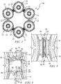
- the combustor assembly 140 is of the can-type and includes a number of individual cans 12 and a number of crossover tubes 10 as shown in Fig. 2 .
- Each can 12 defines a combustion chamber 13 in which a fuel-air mixture is burned.
- Crossover tubes 10 of the present disclosure are positioned between and are used to interconnect the combustion chambers 13 of cans 12 as suggested, for example in Figs. 1 and 2 .
- each crossover tube 10 includes a biasing member 40 that accommodates movement of adjacent cans 12 included in the same combustor assembly 140 during operation of a gas turbine engine 110.
- Cans 12 are self-contained cylindrical combustion chambers, as shown, for example, in Fig. 1 .
- Each can 12 typically includes a fuel nozzle 142 include an igniter (not shown) used to ignite the fuel atomized by the fuel nozzles 142.
- Fuel in cans 12 without igniters are ignited through the use of crossover tubes 10. For the purpose of initial ignition and continuous combustion, it has become customary to join the interiors of adjacent cans 12 through crossover tubes 10, so that when ignition occurs in one of the cans 12, a burning fuel-air mixture will pass through the crossover tubes 10 to ignite the fuel-air mixture in the adjacent cans 12.
- Crossover tubes 10 are adapted to interconnect cans 12, as shown in Figs. 3 and 4 .
- Cans 12 include a cylindrical side wall 14 that is provided with openings 16 or ports formed by annular crossover ferrules 18.
- Crossover ferrules 18 include an annular sidewall 20 and an annular flange 22 that is perpendicularly oriented to the annular sidewall 20.
- Annular sidewall 20 of crossover ferrule 18 is coupled to the side wall 14 of the can 12 at a first end 24 and to annular flange 22 at a second end 26.
- Annular sidewall 20 includes an inside surface 28 and an outside surface 30 that is greater than the inside surface 28. Inside surface 28 is positioned against a portion of crossover tube 10 when crossover tube 10 is positioned within crossover ferrule 18 during assembly.
- Annular flange 22 of crossover ferrules 18 are relatively planar and include a first face 32 and an opposing second face 34.
- First face 32 faces towards can 12 and is coupled to annular sidewall 20.
- Second face 32 of annular flange 22 faces away from can 12 and forms an engagement surface for at least a portion of crossover tubes 10.
- Second face 34 of annular flange 22 faces the second face 34 of an annular flange 22 of an adjacent can 12.
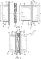
- Crossover tube 10 includes an assembly of components as shown, for example, in Fig. 6 .
- Crossover tube 10 includes an outer member 36, an inner member 38 that is telescopically received in outer member 36 and a biasing member 40 positioned between outer and inner members 36, 38.
- Outer member 36 of crossover tube 10 includes an annular side wall 42, as shown in Figs. 6 and 7 .
- Annular side wall 42 includes a first end 44 and a spaced apart second end 46.
- Annular side wall 42 also includes an inside surface 48 and a spaced apart outer surface 50.
- Annular sidewall 42 has an inner diameter D1 and an outer diameter D2 that is greater than inner diameter D1.
- Outer member 36 of crossover tube 10 also includes an annular flange 52 that is coupled to the second end 46 of annular side wall 42.
- Annular flange 52 extends radially outwardly from outer surface 50 of annular side wall 42 and includes a first face 54 and a spaced apart second face 56. Second face 56 of annular flange 52 is adapted to engage biasing member 40 to provide a support surface for biasing member 40.
- Outer member 36 of crossover tube 10 is preferably machined as a single piece and preferably made from a high temperature metal alloy such as a nickel based cobalt alloy or other alloys that exhibit good high temperature and wear resistance.
- Inner member 38 of crossover tube 10 is configured to telescopingly engage outer member 36 and both are adapted to move collinearly with respect to each other.
- Inner member 38 includes an annular sleeve member 58, an annular side wall 60 and an annular flange 62 positioned between sleeve member 58 and annular side wall 60.
- Sleeve member 58 is adapted to be positioned within annular side wall 42 of outer member 36.
- Annular sleeve member 58 of inner member 38 is tubular in shape and includes a first end 63 and a spaced apart second end 64, as shown in Figs. 6 and 7 .
- Sleeve member 58 includes an inner surface 66 and an outer surface 68.
- Sleeve member 58 has an outer diameter D3 that is less than diameter D1 of annular side wall 42 of outer member 36 to allow sleeve member 58 to fit inside of annular side wall 42, as shown in Fig. 8 .
- the gap between outer surface 68 of sleeve member 58 and inner surface 48 of annular side wall 42 is between .001" and .004" and preferably between .001" and .002" to permit linear movement between the two components, while limiting unwanted blow by of combustion gasses.
- Annular side wall 60 of inner member 38 includes a first end 70 and a spaced apart second end 72, as shown in Fig. 7 .
- Annular side wall 60 also includes an inner surface 74 and an outer surface 76.
- Annular side wall 60 has an outer diameter D4, which is greater than outer diameter D3 of sleeve member 58.
- Outer diameter D4 of annular side wall 60 is the same diameter as outer diameter D2 of annular side wall 42.
- Annular side wall 60 is adapted to be inserted into crossover ferrule 18 of can 12. Once inserted, outer surface 76 of annular side wall 60 is positioned adjacent inside surface 28 of crossover ferrule 18.
- Annular flange 62 of inner member 38 is positioned between annular side wall 60 and sleeve member 58, as shown in Fig. 7 .
- Annular flange 62 is positioned at second end 64 of sleeve member 58 and at first end 70 of annular side wall 60.
- Annular flange 62 of inner member 38 includes a first face 78 and a spaced apart second face 80.
- First face 78 of inner member 38 is adapted to face second face 56 of annular flange 52 of outer member 36.
- Inner member 36 of crossover tube 10 is preferably machined as a single piece and preferably made from a high temperature alloy such as a nickel based cobalt alloy or other alloys that exhibit good high temperature and wear resistance.
- Biasing member 40 is designed to allow for movement between inner member 38 and outer member 36 and maintains force against flanges 52, 62 to secure flanges 52, 62 against crossover ferrules 18.
- Biasing member 40 is in the form of a compression spring such as a coil spring and is preferably a single turn wave spring or a nested wave spring.
- a wave spring also known as a coiled wave spring, a disc spring, or a scrowave spring, is a spring made from pre-hardened flat wire in a process called, on-edge-coiling, also known as edge winding. During this process, waves are added to give it a spring effect. The number of turns and waves can be adjusted to accommodate stronger force.
- a wave spring has the following advantages over a traditional coiled spring or a washer.
- the axial space can be reduced by 50% versus a coil spring.
- an overall size of the crossover tube assembly becomes smaller and thus significant weight reduction.
- the load in an axial direction is 100% transferable.
- Biasing member 40 is preferably made from a nickel based alloy or a stainless alloy for heat resistance. Location of biasing member 40 with respect to outer and inner members 36, 38 protect biasing member 40 from hot combustion gasses. The reduction in heat exposure significantly increases the life of biasing member 40 and reduces metal fatigue.
- crossover tube 81 is a one piece design, as shown in Figs. 3-5 , as opposed to the two piece design shown in Figs. 6-8 , which include outer and inner members 36, 38.
- crossover tube 10 includes a first annular side wall section 82, a second annular side wall section 84 and an annular flange 86.
- First annular side wall section 82 is shorter in axial length than second annular side wall section 84 so that annular flange 86 is closer to first end 88 than to second end 90.
- Annular flange 86 of crossover tube 81 includes a first face 92 and a spaced apart second face 94.
- first annular side wall section 82 is positioned within a first ferrule 18 of a first can 12
- second annular side wall section 84 is positioned within a second ferrule 18 of a second can 12, as shown, for example in Figs. 3-5 .
- Movement of the first can 12 and ferrule 18 toward the second can 12 and ferrule 18 causes movement of the second annular side wall section 84 with respect to the ferrule 18 and compression of biasing member 40, as shown in Fig. 5 .
- crossover tube designs 10, 81 make assembling the cans 12 easier. This is because biasing member 40 of crossover tube compensates for errors in manufacturing tolerances in the cans 12 and ferrules 18 so that spacer washers do not need to be used to take up any unwanted gaps between annular flanges 22 of adjacent ferrules 18. Also, during operation of the engine, heat expansion of the metal and vibration caused by engine operation is absorbed by the crossover tubes and biasing member 40, which reduces wear to cans 12 and ferrules 18. The crossover tube design also controls airflow leakage at the crossover interface between cans 12.
Landscapes
- Engineering & Computer Science (AREA)
- Chemical & Material Sciences (AREA)
- Combustion & Propulsion (AREA)
- Mechanical Engineering (AREA)
- General Engineering & Computer Science (AREA)
- Heat-Exchange Devices With Radiators And Conduit Assemblies (AREA)
Claims (4)
- Brennkammeranordnung (140) zur Verwendung mit einem Turbinenmotor (110), wobei die Brennkammeranordnung (140) umfasst:eine Vielzahl von Büchsen (12), die in einer kreisförmigen Struktur angeordnet sind, wobei jede Büchse (12) eine Brennkammer (13) definiert; wobei jede Büchse eine zylindrische Seitenwand aufweist, die mit Übergangsöffnungen (16) versehen ist, die durch ringförmige Übergangshülsen (18) gebildet sind, wobei jede Übergangshülse eine ringförmige Seitenwand (20) und einen ringförmigen Flansch (22) aufweist, der senkrecht zu der ringförmigen Seitenwand (20) ausgerichtet ist;eine Vielzahl von Übergangsrohrbaugruppen, die zum Verbinden der Büchsen (12) an der Stelle der Übergangsöffnungen (16) verwendet werden, wobei die Übergangsrohrbaugruppen jeweils ein Übergangsrohr (81) umfassen, das als einstückiges Design mit einem ersten ringförmigen Seitenwandabschnitt (82), einem zweiten ringförmigen Seitenwandabschnitt (84) und einem ringförmigen Flansch (86) versehen ist, der sich von dem ersten und zweiten ringförmigen Seitenwandabschnitt (82, 84) radial nach außen erstreckt und eine erste Fläche (92) und eine beabstandete zweite Fläche (94) aufweist, wobei ein Abschnitt des ersten ringförmigen Seitenwandabschnitts (82) innerhalb einer ersten Hülse (18) einer ersten Büchse (12) angeordnet ist; und ein Teil des zweiten ringförmigen Seitenwandabschnitts (84) innerhalb einer zweiten Hülse (18) einer zweiten Büchse (12) angeordnet ist; unddie Übergangsrohrbaugruppen jeweils auch ein Vorspannelement (40) umfassen, das um einen Abschnitt des Übergangsrohrs (81) herum angeordnet ist und dazu angepasst ist, mit dem ringförmigen Flansch (86) des Übergangsrohrs (81) in Eingriff zu kommen.
- Brennkammeranordnung (140) nach Anspruch 1, wobei der erste und der zweite ringförmige Seitenwandabschnitt (82, 84) der Übergangsrohre (81) einen Durchgang zwischen Büchsen (12) bilden, so dass Verbrennungsgase von einer Büchse (12) durch den Durchgang des Übergangsrohrs (81) und zu einer zweiten Büchse (12) gelangen.
- Brennkammeranordnung nach Anspruch 2, wobei das Vorspannelement (40) außerhalb des Durchgangs so angeordnet ist, dass durch den Durchgang strömende Verbrennungsgase das Vorspannelement (40) nicht direkt berühren.
- Brennkammeranordnung (140) nach einem der vorhergehenden Ansprüche, wobei der ringförmige Flansch (86) des Übergangsrohres (81) von einem ersten Ende (88) und einem zweiten Ende (90) des Übergangsrohres (81) beabstandet ist.
Applications Claiming Priority (1)
| Application Number | Priority Date | Filing Date | Title |
|---|---|---|---|
| US201462011732P | 2014-06-13 | 2014-06-13 |
Publications (2)
| Publication Number | Publication Date |
|---|---|
| EP2955447A1 EP2955447A1 (de) | 2015-12-16 |
| EP2955447B1 true EP2955447B1 (de) | 2018-10-24 |
Family
ID=53181079
Family Applications (1)
| Application Number | Title | Priority Date | Filing Date |
|---|---|---|---|
| EP15166865.4A Not-in-force EP2955447B1 (de) | 2014-06-13 | 2015-05-08 | Brennkammer mit federbelastetem verbindungsrohr |
Country Status (2)
| Country | Link |
|---|---|
| US (1) | US10161635B2 (de) |
| EP (1) | EP2955447B1 (de) |
Families Citing this family (11)
| Publication number | Priority date | Publication date | Assignee | Title |
|---|---|---|---|---|
| US20170059165A1 (en) * | 2015-08-28 | 2017-03-02 | Rolls-Royce High Temperature Composites Inc. | Cmc cross-over tube |
| US10563869B2 (en) * | 2016-03-25 | 2020-02-18 | General Electric Company | Operation and turndown of a segmented annular combustion system |
| US10006568B2 (en) | 2016-06-06 | 2018-06-26 | United Technologies Corporation | Double walled tube and manufacture thereof |
| US10156363B2 (en) | 2016-07-20 | 2018-12-18 | General Electric Company | Compact multi-piece spring-loaded crossfire tube |
| US11614233B2 (en) | 2020-08-31 | 2023-03-28 | General Electric Company | Impingement panel support structure and method of manufacture |
| US11994292B2 (en) | 2020-08-31 | 2024-05-28 | General Electric Company | Impingement cooling apparatus for turbomachine |
| US11460191B2 (en) | 2020-08-31 | 2022-10-04 | General Electric Company | Cooling insert for a turbomachine |
| US11994293B2 (en) | 2020-08-31 | 2024-05-28 | General Electric Company | Impingement cooling apparatus support structure and method of manufacture |
| US11371702B2 (en) | 2020-08-31 | 2022-06-28 | General Electric Company | Impingement panel for a turbomachine |
| US11255545B1 (en) | 2020-10-26 | 2022-02-22 | General Electric Company | Integrated combustion nozzle having a unified head end |
| US11767766B1 (en) | 2022-07-29 | 2023-09-26 | General Electric Company | Turbomachine airfoil having impingement cooling passages |
Citations (2)
| Publication number | Priority date | Publication date | Assignee | Title |
|---|---|---|---|---|
| US2437385A (en) * | 1941-11-21 | 1948-03-09 | Dehavilland Aircraft | Jet propulsion plant |
| US2832195A (en) * | 1956-04-16 | 1958-04-29 | Gen Electric | Cross-ignition tube assembly for gas turbine combustion system |
Family Cites Families (59)
| Publication number | Priority date | Publication date | Assignee | Title |
|---|---|---|---|---|
| US2406234A (en) * | 1946-08-20 | Expansion joint | ||
| GB347206A (en) | 1930-01-16 | 1931-04-16 | Frank Whittle | Improvements relating to the propulsion of aircraft and other vehicles |
| US2404334A (en) | 1939-12-09 | 1946-07-16 | Power Jets Res & Dev Ltd | Aircraft propulsion system and power unit |
| FR963784A (de) * | 1947-01-13 | 1950-07-20 | ||
| US2540642A (en) * | 1947-06-19 | 1951-02-06 | Armstrong Siddeley Motors Ltd | Multiple combustion chamber torch igniter and auxiliary fuel spray device arrangement for initiating combustion |
| US2679136A (en) * | 1950-10-21 | 1954-05-25 | Gen Motors Corp | Combustion chamber with crossover tubes |
| US2729938A (en) * | 1951-01-26 | 1956-01-10 | Gen Motors Corp | Combustion chamber crossover tube |
| US2722803A (en) * | 1951-05-23 | 1955-11-08 | Gen Electric | Cooling means for combustion chamber cross ignition tubes |
| US2738471A (en) * | 1952-04-04 | 1956-03-13 | Collins Radio Co | Power amplifier tuning and loading device |
| US2979898A (en) * | 1958-04-25 | 1961-04-18 | United Aircraft Corp | Hooded crossover tube |
| US3001366A (en) * | 1958-05-15 | 1961-09-26 | Gen Motors Corp | Combustion chamber crossover tube |
| US3184918A (en) | 1963-06-18 | 1965-05-25 | United Aircraft Corp | Cooling arrangement for crossover tubes |
| US3492030A (en) * | 1968-09-23 | 1970-01-27 | Atomic Energy Commission | Bellows liner |
| AT279483B (de) * | 1968-10-18 | 1970-03-10 | Flensburger Maschinenbau Ansta | Beschickungswagen, insbesondere zum transport von heiszem schwarzdeckenmischgut |
| US3721089A (en) * | 1971-06-08 | 1973-03-20 | United Aircraft Corp | Crossover tube construction |
| US3811274A (en) * | 1972-08-30 | 1974-05-21 | United Aircraft Corp | Crossover tube construction |
| US3991560A (en) * | 1975-01-29 | 1976-11-16 | Westinghouse Electric Corporation | Flexible interconnection for combustors |
| US4249372A (en) * | 1979-07-16 | 1981-02-10 | General Electric Company | Cross-ignition assembly for combustion apparatus |
| US5001896A (en) * | 1986-02-26 | 1991-03-26 | Hilt Milton B | Impingement cooled crossfire tube assembly in multiple-combustor gas turbine engine |
| JPS6357882U (de) * | 1986-10-04 | 1988-04-18 | ||
| US5154049A (en) | 1990-07-10 | 1992-10-13 | General Electric Company | Tube mounting apparatus including a wire retainer |
| GB9021201D0 (en) * | 1990-09-28 | 1990-11-14 | Ruston Gas Turbines Ltd | Gas turbine combustors |
| US5361577A (en) * | 1991-07-15 | 1994-11-08 | General Electric Company | Spring loaded cross-fire tube |
| US5286071A (en) * | 1992-12-01 | 1994-02-15 | General Electric Company | Bellows sealed ball joint |
| US5407237A (en) * | 1993-02-26 | 1995-04-18 | The United States Of America As Represented By The Secretary Of The Air Force | Flexible coupling |
| FR2704628B1 (fr) | 1993-04-29 | 1995-06-09 | Snecma | Chambre de combustion comportant un système d'injection de comburant à géométrie variable. |
| US5402635A (en) * | 1993-09-09 | 1995-04-04 | Westinghouse Electric Corporation | Gas turbine combustor with cooling cross-flame tube connector |
| US5603531A (en) * | 1994-12-06 | 1997-02-18 | United Technologies Corporation | Blind assembly-swivel crossover tube |
| JP3120049B2 (ja) * | 1996-03-12 | 2000-12-25 | 三菱製鋼株式会社 | コイルドウェーブスプリング及びその製造方法 |
| US5896742A (en) * | 1997-03-20 | 1999-04-27 | General Electric Co. | Tapered cross-fire tube for gas turbine combustors |
| US5964250A (en) * | 1997-12-01 | 1999-10-12 | General Electric Company | Low leakage, articulating fluid transfer tube |
| GB2339468B (en) * | 1998-07-11 | 2002-04-24 | Alstom Gas Turbines Ltd | Gas-turbine engine combustion system |
| US6334294B1 (en) * | 2000-05-16 | 2002-01-01 | General Electric Company | Combustion crossfire tube with integral soft chamber |
| US6606865B2 (en) * | 2001-10-31 | 2003-08-19 | General Electric Company | Bellows type outer crossfire tube |
| US6705088B2 (en) * | 2002-04-05 | 2004-03-16 | Power Systems Mfg, Llc | Advanced crossfire tube cooling scheme for gas turbine combustors |
| US7143583B2 (en) * | 2002-08-22 | 2006-12-05 | Hitachi, Ltd. | Gas turbine combustor, combustion method of the gas turbine combustor, and method of remodeling a gas turbine combustor |
| US6880341B2 (en) * | 2002-12-18 | 2005-04-19 | Pratt & Whitney Canada Corp. | Low cost combustor floating collar with improved sealing and damping |
| US6912838B2 (en) * | 2003-03-06 | 2005-07-05 | Power Systems Mfg, Llc | Coated crossfire tube assembly |
| JP2006083730A (ja) * | 2004-09-15 | 2006-03-30 | Hitachi Ltd | ガスタービンの着火検出方法 |
| US7712302B2 (en) * | 2006-01-05 | 2010-05-11 | General Electric Company | Crossfire tube assembly for gas turbines |
| JP4838763B2 (ja) | 2007-06-11 | 2011-12-14 | 三菱重工業株式会社 | 燃焼振動検出装置の取付構造 |
| JP4959523B2 (ja) * | 2007-11-29 | 2012-06-27 | 株式会社日立製作所 | 燃焼装置,燃焼装置の改造方法及び燃焼装置の燃料噴射方法 |
| JP5456772B2 (ja) * | 2009-05-25 | 2014-04-02 | イーグル工業株式会社 | シール装置 |
| US8220246B2 (en) * | 2009-09-21 | 2012-07-17 | General Electric Company | Impingement cooled crossfire tube assembly |
| JP5156066B2 (ja) * | 2010-08-27 | 2013-03-06 | 株式会社日立製作所 | ガスタービン燃焼器 |
| US9068510B2 (en) * | 2011-11-22 | 2015-06-30 | Delavan, Inc | Machined springs for injector applications |
| US8959925B2 (en) * | 2012-01-18 | 2015-02-24 | General Electric Company | Combustor recovery method and system |
| US9335052B2 (en) * | 2012-11-08 | 2016-05-10 | General Electric Company | Cross-fire tube mounting assembly for a gas turbine engine combustor |
| US9328925B2 (en) * | 2012-11-15 | 2016-05-03 | General Electric Company | Cross-fire tube purging arrangement and method of purging a cross-fire tube |
| US20140137536A1 (en) * | 2012-11-21 | 2014-05-22 | General Electric Company | Super telescoping cross-fire tube and method of assembling a combustor structure |
| US9353952B2 (en) * | 2012-11-29 | 2016-05-31 | General Electric Company | Crossfire tube assembly with tube bias between adjacent combustors |
| JP6325930B2 (ja) * | 2014-07-24 | 2018-05-16 | 三菱日立パワーシステムズ株式会社 | ガスタービン燃焼器 |
| EP3189277B1 (de) * | 2014-09-05 | 2020-04-15 | Siemens Aktiengesellschaft | Überschlagrohr |
| US20160298853A1 (en) * | 2015-04-09 | 2016-10-13 | Siemens Energy, Inc. | Service-friendly cross flame tube with twist lock attachment for can-annular gas turbines |
| US20170059165A1 (en) * | 2015-08-28 | 2017-03-02 | Rolls-Royce High Temperature Composites Inc. | Cmc cross-over tube |
| JP6612165B2 (ja) * | 2016-03-29 | 2019-11-27 | 三菱日立パワーシステムズ株式会社 | ガスタービン燃焼器 |
| US10156363B2 (en) * | 2016-07-20 | 2018-12-18 | General Electric Company | Compact multi-piece spring-loaded crossfire tube |
| JP6590771B2 (ja) * | 2016-08-09 | 2019-10-16 | 三菱日立パワーシステムズ株式会社 | ガスタービン燃焼器 |
| US10247421B2 (en) * | 2016-10-10 | 2019-04-02 | General Electric Company | Tool and method for decoupling cross-fire tube assemblies in gas turbine engines |
-
2015
- 2015-04-08 US US14/681,410 patent/US10161635B2/en active Active
- 2015-05-08 EP EP15166865.4A patent/EP2955447B1/de not_active Not-in-force
Patent Citations (2)
| Publication number | Priority date | Publication date | Assignee | Title |
|---|---|---|---|---|
| US2437385A (en) * | 1941-11-21 | 1948-03-09 | Dehavilland Aircraft | Jet propulsion plant |
| US2832195A (en) * | 1956-04-16 | 1958-04-29 | Gen Electric | Cross-ignition tube assembly for gas turbine combustion system |
Also Published As
| Publication number | Publication date |
|---|---|
| US10161635B2 (en) | 2018-12-25 |
| US20160010868A1 (en) | 2016-01-14 |
| EP2955447A1 (de) | 2015-12-16 |
Similar Documents
| Publication | Publication Date | Title |
|---|---|---|
| EP2955447B1 (de) | Brennkammer mit federbelastetem verbindungsrohr | |
| US11255543B2 (en) | Dilution structure for gas turbine engine combustor | |
| EP1353127B1 (de) | Einteilige ringförmige Verkleidung für Gasturbinenbrennkammer | |
| US10519866B2 (en) | Decoupler assemblies for engine starter | |
| US10935245B2 (en) | Annular concentric fuel nozzle assembly with annular depression and radial inlet ports | |
| US9612017B2 (en) | Combustor with tiled liner | |
| US6725667B2 (en) | Combustor dome for gas turbine engine | |
| JP5149596B2 (ja) | 燃焼器ドームミキサー保持手段 | |
| EP2636952A2 (de) | Kraftstoffdüse und Brennkammer für eine Gasturbine | |
| US9696037B2 (en) | Liner retaining feature for a combustor | |
| JP2017072034A (ja) | ガスタービン用ケーシング及びガスタービン | |
| JP4424553B2 (ja) | ジェットバーナー | |
| EP3441675B1 (de) | Gasturbinenmotor | |
| KR101986021B1 (ko) | 씰링어셈블리 및 이를 포함하는 가스터빈 | |
| CN205425015U (zh) | 燃烧器 | |
| CN110529876A (zh) | 旋转爆轰燃烧系统 | |
| US20190128524A1 (en) | Combustor and gas turbine including the same | |
| JPH09507280A (ja) | ガスタービンエンジン燃焼器に用いられるイグナイタプラグガイド | |
| KR102047369B1 (ko) | 연료 노즐, 이를 포함하는 연소기 및 가스 터빈 | |
| EP3751201B1 (de) | Verfahren und vorrichtung zum installieren/entfernen eines überschlagrohrs | |
| JP2003166716A (ja) | ベローズ形外側火炎伝ぱ管 | |
| EP4524470A1 (de) | Gasturbinentriebwerk und brennstoffdüse dafür | |
| KR101953462B1 (ko) | 베인 어셈블리를갖는 가스터빈 | |
| CN110887060B (zh) | 火焰传播管、燃烧器及包括其的燃气轮机 | |
| US11156162B2 (en) | Fluid manifold damper for gas turbine engine |
Legal Events
| Date | Code | Title | Description |
|---|---|---|---|
| PUAI | Public reference made under article 153(3) epc to a published international application that has entered the european phase |
Free format text: ORIGINAL CODE: 0009012 |
|
| AK | Designated contracting states |
Kind code of ref document: A1 Designated state(s): AL AT BE BG CH CY CZ DE DK EE ES FI FR GB GR HR HU IE IS IT LI LT LU LV MC MK MT NL NO PL PT RO RS SE SI SK SM TR |
|
| AX | Request for extension of the european patent |
Extension state: BA ME |
|
| 17P | Request for examination filed |
Effective date: 20160524 |
|
| RBV | Designated contracting states (corrected) |
Designated state(s): AL AT BE BG CH CY CZ DE DK EE ES FI FR GB GR HR HU IE IS IT LI LT LU LV MC MK MT NL NO PL PT RO RS SE SI SK SM TR |
|
| STAA | Information on the status of an ep patent application or granted ep patent |
Free format text: STATUS: EXAMINATION IS IN PROGRESS |
|
| 17Q | First examination report despatched |
Effective date: 20170201 |
|
| GRAP | Despatch of communication of intention to grant a patent |
Free format text: ORIGINAL CODE: EPIDOSNIGR1 |
|
| STAA | Information on the status of an ep patent application or granted ep patent |
Free format text: STATUS: GRANT OF PATENT IS INTENDED |
|
| INTG | Intention to grant announced |
Effective date: 20180716 |
|
| GRAS | Grant fee paid |
Free format text: ORIGINAL CODE: EPIDOSNIGR3 |
|
| GRAA | (expected) grant |
Free format text: ORIGINAL CODE: 0009210 |
|
| STAA | Information on the status of an ep patent application or granted ep patent |
Free format text: STATUS: THE PATENT HAS BEEN GRANTED |
|
| AK | Designated contracting states |
Kind code of ref document: B1 Designated state(s): AL AT BE BG CH CY CZ DE DK EE ES FI FR GB GR HR HU IE IS IT LI LT LU LV MC MK MT NL NO PL PT RO RS SE SI SK SM TR |
|
| REG | Reference to a national code |
Ref country code: CH Ref legal event code: EP |
|
| REG | Reference to a national code |
Ref country code: IE Ref legal event code: FG4D |
|
| REG | Reference to a national code |
Ref country code: DE Ref legal event code: R096 Ref document number: 602015018556 Country of ref document: DE Ref country code: AT Ref legal event code: REF Ref document number: 1057130 Country of ref document: AT Kind code of ref document: T Effective date: 20181115 |
|
| REG | Reference to a national code |
Ref country code: NL Ref legal event code: MP Effective date: 20181024 |
|
| REG | Reference to a national code |
Ref country code: LT Ref legal event code: MG4D |
|
| REG | Reference to a national code |
Ref country code: AT Ref legal event code: MK05 Ref document number: 1057130 Country of ref document: AT Kind code of ref document: T Effective date: 20181024 |
|
| PG25 | Lapsed in a contracting state [announced via postgrant information from national office to epo] |
Ref country code: NL Free format text: LAPSE BECAUSE OF FAILURE TO SUBMIT A TRANSLATION OF THE DESCRIPTION OR TO PAY THE FEE WITHIN THE PRESCRIBED TIME-LIMIT Effective date: 20181024 |
|
| PG25 | Lapsed in a contracting state [announced via postgrant information from national office to epo] |
Ref country code: FI Free format text: LAPSE BECAUSE OF FAILURE TO SUBMIT A TRANSLATION OF THE DESCRIPTION OR TO PAY THE FEE WITHIN THE PRESCRIBED TIME-LIMIT Effective date: 20181024 Ref country code: NO Free format text: LAPSE BECAUSE OF FAILURE TO SUBMIT A TRANSLATION OF THE DESCRIPTION OR TO PAY THE FEE WITHIN THE PRESCRIBED TIME-LIMIT Effective date: 20190124 Ref country code: IS Free format text: LAPSE BECAUSE OF FAILURE TO SUBMIT A TRANSLATION OF THE DESCRIPTION OR TO PAY THE FEE WITHIN THE PRESCRIBED TIME-LIMIT Effective date: 20190224 Ref country code: LT Free format text: LAPSE BECAUSE OF FAILURE TO SUBMIT A TRANSLATION OF THE DESCRIPTION OR TO PAY THE FEE WITHIN THE PRESCRIBED TIME-LIMIT Effective date: 20181024 Ref country code: HR Free format text: LAPSE BECAUSE OF FAILURE TO SUBMIT A TRANSLATION OF THE DESCRIPTION OR TO PAY THE FEE WITHIN THE PRESCRIBED TIME-LIMIT Effective date: 20181024 Ref country code: BG Free format text: LAPSE BECAUSE OF FAILURE TO SUBMIT A TRANSLATION OF THE DESCRIPTION OR TO PAY THE FEE WITHIN THE PRESCRIBED TIME-LIMIT Effective date: 20190124 Ref country code: PL Free format text: LAPSE BECAUSE OF FAILURE TO SUBMIT A TRANSLATION OF THE DESCRIPTION OR TO PAY THE FEE WITHIN THE PRESCRIBED TIME-LIMIT Effective date: 20181024 Ref country code: ES Free format text: LAPSE BECAUSE OF FAILURE TO SUBMIT A TRANSLATION OF THE DESCRIPTION OR TO PAY THE FEE WITHIN THE PRESCRIBED TIME-LIMIT Effective date: 20181024 Ref country code: LV Free format text: LAPSE BECAUSE OF FAILURE TO SUBMIT A TRANSLATION OF THE DESCRIPTION OR TO PAY THE FEE WITHIN THE PRESCRIBED TIME-LIMIT Effective date: 20181024 Ref country code: AT Free format text: LAPSE BECAUSE OF FAILURE TO SUBMIT A TRANSLATION OF THE DESCRIPTION OR TO PAY THE FEE WITHIN THE PRESCRIBED TIME-LIMIT Effective date: 20181024 |
|
| PG25 | Lapsed in a contracting state [announced via postgrant information from national office to epo] |
Ref country code: PT Free format text: LAPSE BECAUSE OF FAILURE TO SUBMIT A TRANSLATION OF THE DESCRIPTION OR TO PAY THE FEE WITHIN THE PRESCRIBED TIME-LIMIT Effective date: 20190224 Ref country code: AL Free format text: LAPSE BECAUSE OF FAILURE TO SUBMIT A TRANSLATION OF THE DESCRIPTION OR TO PAY THE FEE WITHIN THE PRESCRIBED TIME-LIMIT Effective date: 20181024 Ref country code: RS Free format text: LAPSE BECAUSE OF FAILURE TO SUBMIT A TRANSLATION OF THE DESCRIPTION OR TO PAY THE FEE WITHIN THE PRESCRIBED TIME-LIMIT Effective date: 20181024 Ref country code: GR Free format text: LAPSE BECAUSE OF FAILURE TO SUBMIT A TRANSLATION OF THE DESCRIPTION OR TO PAY THE FEE WITHIN THE PRESCRIBED TIME-LIMIT Effective date: 20190125 Ref country code: SE Free format text: LAPSE BECAUSE OF FAILURE TO SUBMIT A TRANSLATION OF THE DESCRIPTION OR TO PAY THE FEE WITHIN THE PRESCRIBED TIME-LIMIT Effective date: 20181024 |
|
| REG | Reference to a national code |
Ref country code: DE Ref legal event code: R097 Ref document number: 602015018556 Country of ref document: DE |
|
| PG25 | Lapsed in a contracting state [announced via postgrant information from national office to epo] |
Ref country code: DK Free format text: LAPSE BECAUSE OF FAILURE TO SUBMIT A TRANSLATION OF THE DESCRIPTION OR TO PAY THE FEE WITHIN THE PRESCRIBED TIME-LIMIT Effective date: 20181024 Ref country code: IT Free format text: LAPSE BECAUSE OF FAILURE TO SUBMIT A TRANSLATION OF THE DESCRIPTION OR TO PAY THE FEE WITHIN THE PRESCRIBED TIME-LIMIT Effective date: 20181024 Ref country code: CZ Free format text: LAPSE BECAUSE OF FAILURE TO SUBMIT A TRANSLATION OF THE DESCRIPTION OR TO PAY THE FEE WITHIN THE PRESCRIBED TIME-LIMIT Effective date: 20181024 |
|
| PGFP | Annual fee paid to national office [announced via postgrant information from national office to epo] |
Ref country code: DE Payment date: 20190530 Year of fee payment: 5 |
|
| PG25 | Lapsed in a contracting state [announced via postgrant information from national office to epo] |
Ref country code: SK Free format text: LAPSE BECAUSE OF FAILURE TO SUBMIT A TRANSLATION OF THE DESCRIPTION OR TO PAY THE FEE WITHIN THE PRESCRIBED TIME-LIMIT Effective date: 20181024 Ref country code: RO Free format text: LAPSE BECAUSE OF FAILURE TO SUBMIT A TRANSLATION OF THE DESCRIPTION OR TO PAY THE FEE WITHIN THE PRESCRIBED TIME-LIMIT Effective date: 20181024 Ref country code: SM Free format text: LAPSE BECAUSE OF FAILURE TO SUBMIT A TRANSLATION OF THE DESCRIPTION OR TO PAY THE FEE WITHIN THE PRESCRIBED TIME-LIMIT Effective date: 20181024 Ref country code: EE Free format text: LAPSE BECAUSE OF FAILURE TO SUBMIT A TRANSLATION OF THE DESCRIPTION OR TO PAY THE FEE WITHIN THE PRESCRIBED TIME-LIMIT Effective date: 20181024 |
|
| PGFP | Annual fee paid to national office [announced via postgrant information from national office to epo] |
Ref country code: FR Payment date: 20190527 Year of fee payment: 5 |
|
| PLBE | No opposition filed within time limit |
Free format text: ORIGINAL CODE: 0009261 |
|
| STAA | Information on the status of an ep patent application or granted ep patent |
Free format text: STATUS: NO OPPOSITION FILED WITHIN TIME LIMIT |
|
| 26N | No opposition filed |
Effective date: 20190725 |
|
| PG25 | Lapsed in a contracting state [announced via postgrant information from national office to epo] |
Ref country code: SI Free format text: LAPSE BECAUSE OF FAILURE TO SUBMIT A TRANSLATION OF THE DESCRIPTION OR TO PAY THE FEE WITHIN THE PRESCRIBED TIME-LIMIT Effective date: 20181024 |
|
| REG | Reference to a national code |
Ref country code: CH Ref legal event code: PL |
|
| GBPC | Gb: european patent ceased through non-payment of renewal fee |
Effective date: 20190508 |
|
| PG25 | Lapsed in a contracting state [announced via postgrant information from national office to epo] |
Ref country code: CH Free format text: LAPSE BECAUSE OF NON-PAYMENT OF DUE FEES Effective date: 20190531 Ref country code: MC Free format text: LAPSE BECAUSE OF FAILURE TO SUBMIT A TRANSLATION OF THE DESCRIPTION OR TO PAY THE FEE WITHIN THE PRESCRIBED TIME-LIMIT Effective date: 20181024 Ref country code: LI Free format text: LAPSE BECAUSE OF NON-PAYMENT OF DUE FEES Effective date: 20190531 |
|
| REG | Reference to a national code |
Ref country code: BE Ref legal event code: MM Effective date: 20190531 |
|
| PG25 | Lapsed in a contracting state [announced via postgrant information from national office to epo] |
Ref country code: LU Free format text: LAPSE BECAUSE OF NON-PAYMENT OF DUE FEES Effective date: 20190508 |
|
| PG25 | Lapsed in a contracting state [announced via postgrant information from national office to epo] |
Ref country code: TR Free format text: LAPSE BECAUSE OF FAILURE TO SUBMIT A TRANSLATION OF THE DESCRIPTION OR TO PAY THE FEE WITHIN THE PRESCRIBED TIME-LIMIT Effective date: 20181024 |
|
| PG25 | Lapsed in a contracting state [announced via postgrant information from national office to epo] |
Ref country code: IE Free format text: LAPSE BECAUSE OF NON-PAYMENT OF DUE FEES Effective date: 20190508 Ref country code: GB Free format text: LAPSE BECAUSE OF NON-PAYMENT OF DUE FEES Effective date: 20190508 |
|
| PG25 | Lapsed in a contracting state [announced via postgrant information from national office to epo] |
Ref country code: BE Free format text: LAPSE BECAUSE OF NON-PAYMENT OF DUE FEES Effective date: 20190531 |
|
| REG | Reference to a national code |
Ref country code: DE Ref legal event code: R119 Ref document number: 602015018556 Country of ref document: DE |
|
| PG25 | Lapsed in a contracting state [announced via postgrant information from national office to epo] |
Ref country code: FR Free format text: LAPSE BECAUSE OF NON-PAYMENT OF DUE FEES Effective date: 20200531 |
|
| PG25 | Lapsed in a contracting state [announced via postgrant information from national office to epo] |
Ref country code: CY Free format text: LAPSE BECAUSE OF FAILURE TO SUBMIT A TRANSLATION OF THE DESCRIPTION OR TO PAY THE FEE WITHIN THE PRESCRIBED TIME-LIMIT Effective date: 20181024 Ref country code: DE Free format text: LAPSE BECAUSE OF NON-PAYMENT OF DUE FEES Effective date: 20201201 |
|
| PG25 | Lapsed in a contracting state [announced via postgrant information from national office to epo] |
Ref country code: HU Free format text: LAPSE BECAUSE OF FAILURE TO SUBMIT A TRANSLATION OF THE DESCRIPTION OR TO PAY THE FEE WITHIN THE PRESCRIBED TIME-LIMIT; INVALID AB INITIO Effective date: 20150508 Ref country code: MT Free format text: LAPSE BECAUSE OF FAILURE TO SUBMIT A TRANSLATION OF THE DESCRIPTION OR TO PAY THE FEE WITHIN THE PRESCRIBED TIME-LIMIT Effective date: 20181024 |
|
| PG25 | Lapsed in a contracting state [announced via postgrant information from national office to epo] |
Ref country code: MK Free format text: LAPSE BECAUSE OF FAILURE TO SUBMIT A TRANSLATION OF THE DESCRIPTION OR TO PAY THE FEE WITHIN THE PRESCRIBED TIME-LIMIT Effective date: 20181024 |