EP2955409B1 - Suspension mount - Google Patents
Suspension mount Download PDFInfo
- Publication number
- EP2955409B1 EP2955409B1 EP13874462.8A EP13874462A EP2955409B1 EP 2955409 B1 EP2955409 B1 EP 2955409B1 EP 13874462 A EP13874462 A EP 13874462A EP 2955409 B1 EP2955409 B1 EP 2955409B1
- Authority
- EP
- European Patent Office
- Prior art keywords
- inclined portion
- elastomer
- extended portion
- elastomer member
- suspension
- Prior art date
- Legal status (The legal status is an assumption and is not a legal conclusion. Google has not performed a legal analysis and makes no representation as to the accuracy of the status listed.)
- Active
Links
Images


Classifications
-
- B—PERFORMING OPERATIONS; TRANSPORTING
- B60—VEHICLES IN GENERAL
- B60G—VEHICLE SUSPENSION ARRANGEMENTS
- B60G15/00—Resilient suspensions characterised by arrangement, location or type of combined spring and vibration damper, e.g. telescopic type
- B60G15/08—Resilient suspensions characterised by arrangement, location or type of combined spring and vibration damper, e.g. telescopic type having fluid spring
-
- B—PERFORMING OPERATIONS; TRANSPORTING
- B60—VEHICLES IN GENERAL
- B60G—VEHICLE SUSPENSION ARRANGEMENTS
- B60G13/00—Resilient suspensions characterised by arrangement, location or type of vibration dampers
- B60G13/001—Arrangements for attachment of dampers
- B60G13/003—Arrangements for attachment of dampers characterised by the mounting on the vehicle body or chassis of the damper unit
-
- B—PERFORMING OPERATIONS; TRANSPORTING
- B60—VEHICLES IN GENERAL
- B60G—VEHICLE SUSPENSION ARRANGEMENTS
- B60G2204/00—Indexing codes related to suspensions per se or to auxiliary parts
- B60G2204/10—Mounting of suspension elements
- B60G2204/12—Mounting of springs or dampers
- B60G2204/128—Damper mount on vehicle body or chassis
-
- B—PERFORMING OPERATIONS; TRANSPORTING
- B60—VEHICLES IN GENERAL
- B60G—VEHICLE SUSPENSION ARRANGEMENTS
- B60G2204/00—Indexing codes related to suspensions per se or to auxiliary parts
- B60G2204/40—Auxiliary suspension parts; Adjustment of suspensions
- B60G2204/41—Elastic mounts, e.g. bushings
-
- B—PERFORMING OPERATIONS; TRANSPORTING
- B60—VEHICLES IN GENERAL
- B60G—VEHICLE SUSPENSION ARRANGEMENTS
- B60G2206/00—Indexing codes related to the manufacturing of suspensions: constructional features, the materials used, procedures or tools
- B60G2206/01—Constructional features of suspension elements, e.g. arms, dampers, springs
- B60G2206/80—Manufacturing procedures
-
- F—MECHANICAL ENGINEERING; LIGHTING; HEATING; WEAPONS; BLASTING
- F16—ENGINEERING ELEMENTS AND UNITS; GENERAL MEASURES FOR PRODUCING AND MAINTAINING EFFECTIVE FUNCTIONING OF MACHINES OR INSTALLATIONS; THERMAL INSULATION IN GENERAL
- F16F—SPRINGS; SHOCK-ABSORBERS; MEANS FOR DAMPING VIBRATION
- F16F1/00—Springs
- F16F1/36—Springs made of rubber or other material having high internal friction, e.g. thermoplastic elastomers
- F16F1/42—Springs made of rubber or other material having high internal friction, e.g. thermoplastic elastomers characterised by the mode of stressing
- F16F1/44—Springs made of rubber or other material having high internal friction, e.g. thermoplastic elastomers characterised by the mode of stressing loaded mainly in compression
- F16F1/445—Springs made of rubber or other material having high internal friction, e.g. thermoplastic elastomers characterised by the mode of stressing loaded mainly in compression the spring material being contained in a generally closed space
-
- F—MECHANICAL ENGINEERING; LIGHTING; HEATING; WEAPONS; BLASTING
- F16—ENGINEERING ELEMENTS AND UNITS; GENERAL MEASURES FOR PRODUCING AND MAINTAINING EFFECTIVE FUNCTIONING OF MACHINES OR INSTALLATIONS; THERMAL INSULATION IN GENERAL
- F16F—SPRINGS; SHOCK-ABSORBERS; MEANS FOR DAMPING VIBRATION
- F16F2228/00—Functional characteristics, e.g. variability, frequency-dependence
- F16F2228/08—Functional characteristics, e.g. variability, frequency-dependence pre-stressed
-
- F—MECHANICAL ENGINEERING; LIGHTING; HEATING; WEAPONS; BLASTING
- F16—ENGINEERING ELEMENTS AND UNITS; GENERAL MEASURES FOR PRODUCING AND MAINTAINING EFFECTIVE FUNCTIONING OF MACHINES OR INSTALLATIONS; THERMAL INSULATION IN GENERAL
- F16F—SPRINGS; SHOCK-ABSORBERS; MEANS FOR DAMPING VIBRATION
- F16F9/00—Springs, vibration-dampers, shock-absorbers, or similarly-constructed movement-dampers using a fluid or the equivalent as damping medium
- F16F9/32—Details
- F16F9/54—Arrangements for attachment
Landscapes
- Engineering & Computer Science (AREA)
- Mechanical Engineering (AREA)
- Vehicle Body Suspensions (AREA)
- Springs (AREA)
- Fluid-Damping Devices (AREA)
- Vibration Prevention Devices (AREA)
Description
- The present invention relates to a suspension mount according to the preamble of claim 1 which connects with a vehicle body a suspension member which constitutes a suspension mechanism of the vehicle.
- Conventionally, a strut mount as shown in the following patent document 1 (PTL1) is known, for example. This conventional strut mount comprises an inside clasp attached to a piston rod and an outside clasp connected with the inside clasp through an elastic member. Here, the elastic member used for this conventional strut mount consists of a first rubber and a second rubber with a dynamic multiplication, which is a ratio of a spring constant under a dynamic load to a spring constant under a static load, and a damping characteristic tan δ larger than those of the first rubber. The first rubber and the second rubber are integrally attached at least to the inside clasp, and the first rubber is configured to contact with the faceplate portion of the outside clasp under an overall range of load including no load, and the second rubber is configured to contact with the faceplate portion of the outside clasp only under a load exceeding a predetermined value.
- Moreover, conventionally, a strut mount as shown in the following patent document 2 (PTL2) is also known. This conventional strut mount comprises an inner cylinder fixed at the end of a piston rod of a shock absorber, a vibration-isolation substrate consisting of a rubber-like elastic object disposed in this inner cylinder and a pair of upper and lower brackets which forms a housing portion for containing this vibration-isolation substrate and is fixed to the vehicle body side by a plurality of mounting members.
- Moreover, conventionally, a strut mount as shown in the following patent document 3 (PTL3) is also known, for example. This conventional strut mount comprises an outer member, an inner mounting member and an elastic object, and the elastic object consists of a rubber elastic portion and a low-density portion. This rubber elastic portion is cure-adhered to the inner mounting member, and its upper surface and lower surface are formed in a shape of a wave which has amplitude in an axial direction of the strut mount. The low-density portion is formed of an expandable urethane and a soft rubber, etc., for example.
- Furthermore, conventionally, a strut mount as shown in the following patent document 4 (PTL4) is also known, for example. This conventional strut mount comprises an outside clasp attached to a vehicle body, an inside clasp attached to a piston rod of a shock absorber, and a rubber elastic object interposed between the outside clasp and the inside clasp by being pressed Into a housing portion of the outside clasp in a status that it is formed integrally with the inside clasp at the outer periphery of the inside clasp. This conventional strut mount is configured so that a soft layer (urethane) with a higher loss coefficient and a lower density than those of the rubber elastic object is interposed between the outside clasp and the rubber elastic object and thereby the soft layer absorbs a minute high-frequency oscillation and the rubber elastic object absorbs a big external force.
- Patent document 5 (PTL5) shows a generic suspension mount according to the preamble of claim 1.
-
- [PTL1]
JP 2010 281412 A - [PTL2]
JP 2006 219106 A - [PTL3]
JP 2010 090995 A - [PTL4]
JP 2007 100889 A - [PTL5]
DE 10 2007 026471 A1 - By the way, in the conventional strut mounts shown in the above-mentioned patent documents 1 and 2 (PTLs 1 and 2), an elastic member and/or a vibration-isolation substrate mainly consisting of a rubber material are adopted. Here, the rubber material can usually demonstrate an elastic force promptly against a deformation accompanied by an input. For this reason, when a strut mount which adopts an elastic member and/or a vibration-isolation substrate mainly consisting of a rubber material connects a suspension member, such as a shock absorber, with a vehicle body, the elastic member and the vibration-isolation substrate can generate an elastic force for controlling displacements of the vehicle In a up-and-down, front-and-rear and left-and-right directions in the shock absorber, etc., promptly against these displacements (upon the initiation of these displacements). Therefore, a strut mount which adopts an elastic member and a vibration-isolation substrate mainly consisting of the above-mentioned rubber material can demonstrate an elastic force suitable for a suspension member not only against a displacement of a vehicle in a up-and-down direction, but also against displacements of the vehicle in a front-and-rear and left-and-right directions. In other words, the strut mount is configured to be able to demonstrate a suitable characteristic (spring constant).
- However, an elastic member and vibration-isolation substrate mainly consisting of a rubber material are attached to an inside clasp or inner cylinder (strut mount) in a status that they have a desired characteristic (spring constant) through what is called a cure-adhesion. Therefore, a process for the cure-adhesion of the elastic member and/or vibration-isolation substrate is needed separately. In this connection, elastomeric materials, such as an expandable urethane etc. adopted as a low-density portion and/or soft layer in the conventional strut mounts disclosed in the above-mentioned patent documents 3 and 4 (PTLs 3 and 4), do not need a cure-adhesion process, and can be attached to a strut mount after being formed in a predetermined shape beforehand.
- Here, an expandable urethane etc. which is an elastomeric material, demonstrates an elastic force promptly against a deformation accompanied by an input In other words, since it has a desired characteristic (spring constant), it is important to be maintained at a status that it is compressed to a predetermined compressibility beforehand (a precompressed status), as shown in
Fig. 8 . Namely, as shown inFig. 8 , in a no load status (a) that it is not precompressed, an unnecessary region where an elastic force does not increase against an increasing displacement (stroke) appears in an early period after an input was started, and thereafter a necessary region where an elastic force increases against an increasing displacement (stroke) appears. Therefore, in the status with no precompression, since a useless displacement (stroke) occurs in the unnecessary region, a total displacement (stroke) becomes large and an elastic force cannot be generated with a sufficient responsibility. On the other hand, in a precompressed status (b) that it is precompressed, the necessary region where an elastic force increases against an increasing displacement (stroke) appears from the early period after an input was started. Namely, in the precompressed status, since the necessary region can be generated from an early period of the input, a total displacement (stroke) becomes small and an elastic force can be generated with a sufficient responsibility. - Based on such a characteristic, when the above-mentioned elastic member and/or vibration-isolation substrate is formed only of an elastomeric material which consists of an expandable urethane, etc. and is held being compressed (precompressed) between an inside clasp and an outside clasp and/or between an inner cylinder and a bracket, for instance, the elastic member and/or vibration-isolation substrate can demonstrate an elastic force with a sufficient responsibility against a displacement in an axial direction of a shock absorber connected with a strut mount, etc. (for instance, in a up-and-down direction of the vehicle). In other words, the strut mount can demonstrate a suitable characteristic (spring constant).
- On the other hand, an elastomeric material such as an expandable urethane, in spite of the presence or absence of the above-mentioned precompression, an elastic force can be generated also by enlarging a pressure receiving area, as shown in
Fig. 9 . Namely, as shown inFig. 9 , although a status that an elastic force does not increase against an increasing displacement (stroke) after an input is started continues in the case where the pressure receiving area is A0, an elastic force increases against an increasing displacement (stroke) after an input is started in a case where the pressure receiving area is A1 which is larger than the pressure receiving area A0. Namely, an elastic force can be generated from an early period of an input (early period of a stroke) by enlarging a pressure receiving area. - Here, when an elastic member and/or vibration-isolation substrate formed only of an elastomeric material consisting of an expandable urethane, etc. are compressed (precompressed) and held between an inside clasp and an outside clasp and/or between an inner cylinder and a bracket, a status that the elastic member and/or vibration-isolation substrate are precompressed in an axial direction of a shock absorber, etc., i.e. an axial direction of the inside clasp and an inner cylinder can be secured, as mentioned above. However, since the elastic member and/or vibration-isolation substrate cannot be precompressed in an axially-perpendicular direction which is a direction perpendicular to the axial direction of the inside clasp and/or inner cylinder, an elastic force cannot be given with a sufficient responsibility against a displacement in the axially-perpendicular direction of the shock absorber, etc. (for instance, in front-and-rear and left-and-right directions of a vehicle). Therefore, in order to give an elastic force against a displacement in the axially-perpendicular direction of the shock absorber, etc., i.e. the inside clasp and/or inner cylinder (in the front-and-rear and left-and-right directions of the vehicle), it can be supposed to increase the area of a contact portion with the elastic member and/or vibration-isolation substrate in the axial direction of the inside clasp and/or inner cylinder, i.e., the pressure receiving area. Specifically, it can be supposed to cylindrically extend the elastic member and/or vibration-isolation substrate along the axial direction of the strut mount (shock absorber, etc.).
- However, as apparent from
Fig. 8 andFig. 9 , even if a pressure receiving area is enlarged, when an elastic member and/or vibration-isolation substrate is not precompressed, it is difficult to give a suitable elastic force with a sufficient responsibility against a displacement in an axially-perpendicular direction of a shock absorber, etc. (in front-and-rear and left-and-right directions of a vehicle). Therefore, in a conventional strut mount, since an elastic member and/or vibration-isolation substrate, etc. formed only of an elastomeric material can be precompressed only in a specific direction (axial direction of a shock absorber, etc.), it is difficult to demonstrate a suitable characteristic (spring constant) in an axial direction and an axially-perpendicular direction, and its adoption to vehicles may be limited. Moreover, when a pressure receiving area is enlarged in order to demonstrate the characteristic against the displacement in the axially-perpendicular direction, this leads to an enlargement of the dimension (height dimension) of a strut mount in its axial direction, and this may affect a configuration of various mechanisms aiming at pedestrian protection, for example, especially in a case where the strut mount is arranged in the front portion of a vehicle. - The present invention has been made in order to cope with the above-mentioned issues, and the objective thereof is to provide a small and simply structured suspension mount which adopts an expandable resin elastomer and which is capable of improving responsibility to displacement of the suspension member in any direction.
- In order to achieve the above-mentioned objective, a feature of the present invention is in that a suspension mount which connects with a vehicle body a suspension member constituting a suspension mechanism of the vehicle comprises an inside member connected with said suspension member, an expandable resin elastomer which clamps an extended portion formed of an expandable resin and extended from said inside member, a case member which has a containing portion for integrally containing said inside member and said expandable resin elastomer, a plate member which is integrally adhered to an opening end of said case member and has a compression surface for compressing said expandable resin elastomer contained inside of said containing portion of said case member, along with a bottom Inner surface of said case member, in a status that said expandable resin elastomer clasps said extended portion of said inside member, and a compressing means -for compressing said expandable resin elastomer in an extending direction of said extended portion of said inside member in association with the compression of said expandable resin elastomer by said bottom inner surface of said case member and said compression surface of said plate member. In this case, said suspension member is a shock absorber, for example, and said inside member is connected with an absorber rod of this shock absorber.
- Moreover, in these cases, said compressing - means is configured to comprise an inclined portion formed at least on one side of clamped surfaces of said extended portion of said inside member, which are clamped by said expandable resin elastomer. And in this case, said inclined portion may be formed so that its thickness becomes thinner towards the outer edge of said extended portion In an extending direction of said extended portion.
- In these cases, when said inclined portion is formed at least on the clamped surface opposed to said compression surface of said plate member among said clamped surfaces of said extended portion, said compressing means may be configured to further comprise a plate member side inclined portion formed on said compression surface of said plate member. In this case, said plate member side- inclined portion may be formed so that its thickness becomes thicker towards the outer edge of said extended portion in an extending direction of said extended portion.
- Moreover, in these cases, when said inclined portion is formed at leat on the clamped surface opposed to said bottom inner surface of said case member among said clamped surfaces of said extended portion, said compressing means may be configured to further comprise a case member side inclined portion formed on said bottom inner surface of said case member. In this case, said case member side inclined portion may be formed so that its thickness becomes thicker towards the outer edge of said extended portion, to which said case member side inclined portion is opposed, in an extending direction of said extended portion.
- Furthermore, in these cases, said compressing means may compress said expandable resin elastomer to different compression states along the circumference direction of said inside member. In this case, specifically, said expandable resin elastomer can be compressed to different compression states by changing the angle of inclination of said inclined portion formed on said extended portion of said inside member along the circumference direction of said inside member. Moreover, said expandable resin elastomer can be compressed to different compression states by changing the angle of inclination of said plate member side inclined portion formed on said compression surface of said plate member along the circumference direction of said inside member. Furthermore, said expandable resin elastomer can be compressed to different compression states by changing the angle of inclination of said case member side inclined portion -formed on said bottom inner surface of said case member along the circumference direction of said inside member. In these cases, said compressing means can compress said expandable resin elastomer to different compression states along the circumference direction of said inside member, depending on the extent of an elastic force required for a displacement of said suspension member connected with said inside member in front-and-rear and left-and-right directions of a vehicle.
- In accordance with the above, the suspension mount using an expandable resin elastomer comprises a compression means, specifically an inclined portion, for compressing the expandable resin elastomer in the extending direction of the extended portion of the inside member. Thereby, the compressing means can generate a compressive load by compressing said expandable resin elastomer also in the extending direction of the extended portion of the inside member, in association with the compression of the expandable resin elastomer by the bottom inner surface of the case member and the compression surface of the plate member (i.e., in association with the generation of a compressive load). Therefore, the expandable resin elastomer can be held in a status that it is precompressed in an axial direction of the suspension mount and in an axially-perpendicular direction which is a direction perpendicular to this axial direction (the extending direction of the extended portion of the inside member), for example. Thereby, when a shock absorber which is the suspension member connected with the vehicle body through the suspension mount is displaced (vibrates) in the up-and-down, front-and-rear and left-and-right directions of the vehicle, the expandable resin elastomer in a precompressed status can give a desired elastic force with a sufficient responsibility. As a result, the suspension mount can demonstrate a desired characteristic and can properly control the displacement of the shock absorber. Namely, it becomes possible for the suspension mount to control a vibration characteristic between a wheel and the vehicle body not only in the axial direction, but also in the axially-perpendicular direction (in the extending direction of the extended portion of the inside member).
- Moreover, by the compressing means, a compressive load can be generated also in the axially-perpendicular direction (the extending direction of the extended portion of the inside member) to precompress the expandable resin elastomer. For this reason, it is not necessary to enlarge a pressure receiving area with the expandable resin elastomer in the axial direction of the inside member, and it is not necessary to increase the dimension in the height direction of the suspension mount Therefore, the suspension mount can be miniaturized while securing a desired characteristic.
- Furthermore, as the expandable resin, an elastomeric material (polyurethane elastomer foam) can be adopted, for example. Thereby, the expandable resin elastomer can be easily formed in a desired shape, and it is not necessary to include a process of a cure-adhesion in an assembly of the suspension mount, unlike a rubber material. Therefore, easy processing can be secured while a manufacturing cost can be reduced.
-
-
Fig. 1 is a sectional view for showing the configuration of a suspension mount according to an embodiment of the present invention in detail. -
Fig. 2 is an expanded sectional view for explaining the compression state of an elastomer member in the suspension mount shown inFig. 1 . -
Fig. 3 is a view for explaining a change of a compressive load accompanying a change of the angle of inclination in an inclined portion in an inner plate, according to the first modification of the embodiment of the present invention. -
Fig. 4 is a view for explaining an arrangement of an inclined portion (presence or absence of an inclined portion) and a continuous change of the angle of inclination of the inclined portion in an inner plate, according to the second modification of the embodiment of the present invention. -
Fig. 5 is a view for explaining a configuration (one side configuration) of an inclined portion in an inner plate, according to the third modification of the embodiment of the present invention. -
Fig. 6 is a view for explaining an arrangement of a lower case side inclined portion and an upper plate side inclined portion in a lower case and an upper plate, according to the third modification of the embodiment of the present invention. -
Fig. 7 is a view for explaining an arrangement of a lower case side inclined portion portion and an upper plate side inclined portion (presence or absence of an inclined portion portion) and a continuous change of the angle of inclination of the inclined portion, according to the third modification of the embodiment of the present invention. -
Fig. 8 is a view for explaining a change of a generation status of an elastic force in accordance with the presence or absence of a precompression in an elastomeric material (urethane). -
Fig. 9 is a view for explaining a change of a generation status of an elastic force in accordance with a change of a pressure receiving area in an elastomeric material (urethane). - Hereafter, a suspension mount according to an embodiment of the present invention will be explained using drawings.
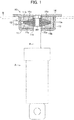
Fig. 1 is a sectional view for showing roughly the configuration of a suspension member which constitutes a suspension mechanism of a vehicles, specifically asuspension mount 10 which connects with a vehicle body B a shock absorber A constituting a strut-type suspension mechanism, according to one embodiment of the present invention. Here, thesuspension mount 10 in this embodiment is attached to the front side fender apron of the vehicle body B, etc. through a volt, and is used as an upper mount which connects the shock absorber A with the vehicle body B, for example. - The
suspension mount 10 is constituted by aninner plate 11 as a inside member, anelastomer member 12 as an expandable resin elastomer, alower case 13 as a case member, and anupper plate 14 as a plate member, as shown inFig. 1 . - The
inner plate 11 is connected with the shock absorber A, and has acylinder portion 11a made of metal and an annularextended portion 11b which extends outwards in a radial direction from the outer periphery surface of thecylinder portion 11a. Thecylinder portion 11a is connected with the shock absorber A by a nut being screwed on a screw part formed at a tip portion R1 of an absorber rod of the shock absorber A in a status that the tip portion R1 is inserted in the cylinder portion. In addition, although theinner plate 11 has thecylinder portion 11a in this embodiment, thecylinder portion 11a can be omitted if theinner plate 11 can be connected with the absorber rod R of the shock absorber A. - The
extended portion 11b is clamped by theelastomer member 12. And aninclined portion 11c which constitutes a compressing means is integrally formed in theextended portion 11b of theinner plate 11. Specifically, theinclined portion 11c in this embodiment is formed in a tapered shape around its whole circumference with a thickness decreasing towards the outer edge of theextended portion 11b in an extending direction of theextended portion 11b, i.e., outwards in a radial direction from the center of theinner plate 11. Therefore, it is also possible to integrally form theinclined portion 11c by decreasing the board thickness of theextended portion 11b in its extending direction, for example. - The
elastomer member 12 is constituted by thefirst elastomer member 12a and thesecond elastomer member 12b, as shown inFig. 1 . Here, the elastomer member 12 (thefirst elastomer member 12a and thesecond elastomer member 12b) which is an expandable resin elastomer can be formed using a foamed object of a polyurethane elastomer as an expandable resin. In addition, in this embodiment, for example, in consideration of an attachment property and a desired characteristic (spring constant after attachment), etc., theelastomer member 12 is constituted by thefirst elastomer member 12a and thesecond elastomer member 12b with predetermined thicknesses. However, it is needless to say that theelastomer member 12 does not have to be divided. - The
lower case 13 is made of metal and is formed in a bottomed cylindrical shape whose cross-section shape is approximately U-shaped to form a containingportion 13a, as shown inFig. 1 . The containingportion 13a contains thefirst elastomer member 12a, theinner plate 11 and thesecond elastomer member 12b in order. Moreover, the through-hole 13c, in which the absorber rod R of the shock absorber A to be connected with theinner plate 11 is inserted, is formed in a bottominner surface 13b which forms the containingportion 13a. - The
upper plate 14 is a thin plate made of metal, and is integrally adhered to the opening end of thelower case 13 in a status that thefirst elastomer member 12a, theinner plate 11 and thesecond elastomer member 12b are contained in order in the containingportion 13a of thelower case 13, as shown inFig. 1 . Thus, theupper plate 14 is integrally adhered to thelower case 13 and thereby a portion of theupper plate 14, which contacts with thesecond elastomer member 12b, i.e., acompression surface 14a, and the bottominner surface 13b of thelower case 13 compresses thefirst elastomer member 12a and thesecond elastomer member 12b which clamp theinclined portion 11c formed in theextended portion 11b of theinner plate 11 and are contained within the containingportion 13a to a predetermined compressibility. - The compression of the
first elastomer member 12a and thesecond elastomer member 12b accompanying attachment of thisupper plate 14 to thelower case 13 will be concretely explained below usingFig. 2 . Thefirst elastomer member 12a and thesecond elastomer member 12b are formed so that it has a predetermined thickness in a no-load status, based on its desired characteristic (spring constant) after attachment, i.e., in a precompressed status. For this reason, as shown inFig. 2 (a) , at the beginning of compression, the thicknesses of thefirst elastomer member 12a and thesecond elastomer member 12b are large, and they are gradually compressed with a displacement of the upper plate 14 (inFig. 2 , it descends toward the bottom of the plane of drawing). - At this time, the
first elastomer member 12a and thesecond elastomer member 12b are compressed in a status that they clamp theinclined portion 11c integrally formed in theextended portion 11b of theinner plate 11. For this reason, by theinclined portion 11c in contact with thesecond elastomer member 12b, the downward input which acts on thesecond elastomer member 12b with a displacement (descent) of thecompression surface 14a in theupper plate 14 is decomposed into a compressive load in the axial direction of the suspension mount 10 (inFig. 2 , it is a direction toward the top of the plane of drawing) and a compressive load in an axially-perpendicular direction which is perpendicular to the axial direction (inFig. 2 , it is a left-and-right direction, and corresponds to the extending direction of theextended portion 11b of theinner plate 11 in this embodiment). - On the other hand, an upward input acts on the
first elastomer member 12a from the bottominner surface 13b of thelower case 13, as a reaction force accompanying a displacement (descent) of thecompression surface 14a in theupper plate 14. For this reason, by theinclined portion 11c in contact with thefirst elastomer member 12a, the upward input which acts on thefirst elastomer member 12a is decomposed into a compressive load in the axial direction of the suspension mount 10 (inFig. 2 , it is a direction toward the bottom of the plane of drawing) and a compressive load in an axially-perpendicular direction which is perpendicular to the axial direction (inFig. 2 , it is a left-and-right direction, and corresponds to the extending direction of theextended portion 11b of theinner plate 11 in this embodiment). - And when the compression is completed by a displacement (descent) of the
compression surface 14a in theupper plate 14 as shown in (b), a suitable compressibility in the axial direction of thefirst elastomer member 12a and thesecond elastomer member 12b will be secured. Thereby, respectively on thefirst elastomer member 12a and thesecond elastomer member 12b, while a compressive load acts in an up-and-down axial direction, a compressive load acts in a left-and-right axially-perpendicular direction (the extending direction of theextended portion 11b of the inner plate 11). Therefore, for example, in a case where the shock absorber A is connected with the vehicle body B through thissuspension mount 10, when the shock absorber A, in other words, theinner plate 11 integrally connected therewith, is displaced (vibrates) in the up-and-down, front-and-rear and left-and-right directions of the vehicle, thefirst elastomer member 12a and thesecond elastomer member 12b (elastomer member 12) in a precompressed status can give a suitable elastic force with a sufficient responsibility against the above-mentioned displacement of the inner plate 11 (shock absorber A). Namely, thesuspension mount 10 can demonstrate a suitable characteristic (spring constant) against the displacement of the shock absorber A in the up-and-down, left-and-right and front-and-rear directions of the vehicle. - Here, for reference, a conventional-
type suspension mount 10 wherein aninclined portion 11c is not formed in theinner plate 11 is supposed as a specimen for reference, and the precompressed status of thefirst elastomer member 12a and thesecond elastomer member 12b in this supposed suspension mount 10 (specimen for reference) will be explained. As for thesuspension mount 10 wherein theinclined portion 11c is not formed in theinner plate 11 like a conventional type, as shown inFig. 2 (c) , only a compressive load in an up-and-down axial direction acts on thefirst elastomer member 12a and thesecond elastomer member 12b with a displacement (descent) of thecompression surface 14a in theupper plate 14. Namely, in such asuspension mount 10, thefirst elastomer member 12a and thesecond elastomer member 12b are in a status that they are precompressed only in the axial direction and are not precompressed in an axially-perpendicular direction at all. For this reason, for example, although they can give a suitable elastic force with a sufficient responsibility only against a displacement of the inner plate 11 (shock absorber A) in the up-and-down direction of the vehicle, an elastic force cannot be demonstrated against a displacement of the inner plate 11 (shock absorber A) in the left-and-right and front-and-rear directions of the vehicle. - As can be understood from the above explanation, in accordance with the above-mentioned embodiment, in the
suspension mount 10 using the elastomer member 12 (thefirst elastomer member 12a and thesecond elastomer member 12b) as an expandable resin, theinclined portion 11c which constitutes a compressing means can be formed in theextended portion 11b of theinner plate 11. Thereby, while the elastomer member 12 (thefirst elastomer member 12a and thesecond elastomer member 12b) generates a compressive load in the axial direction of the suspension mount 10 (shock absorber A), it can generate a compressive load also in the axially-perpendicular direction (the extending direction of theextended portion 11b of the inner plate 11). Therefore, the elastomer member 12 (thefirst elastomer member 12a and thesecond elastomer member 12b) can be held in a state that it is precompressed in the axial direction and the axially-perpendicular direction. Thereby, when the shock absorber A connected with the vehicle body B through thesuspension mount 10 is displaced (vibrates) in the up-and-down, left-and-right and front-and-rear directions of the vehicle, the elastomer member 12 (thefirst elastomer member 12a and thesecond elastomer member 12b) can give a desired elastic force with a sufficient responsibility and, as a result, thesuspension mount 10 can demonstrate a desired characteristic and can properly control the displacement of the shock absorber A. Namely, it becomes possible for thesuspension mount 10 to control the vibration characteristic between a wheel and the vehicle body B not only in the axial direction, but also in the axially-perpendicular direction (the extending direction of theextended portion 11b of the inner plate 11). - Moreover, by forming the
inclined portion 11c as a compressing means, a compressive load is generated and a precompression can be carried out also in the axially-perpendicular direction. For this reason, it is not necessary to enlarge a pressure receiving area with the elastomer member 12 (thefirst elastomer member 12a and thesecond elastomer member 12b) in the axial direction of theinner plate 11, and it is not necessary to increase the dimension in the height direction of thesuspension mount 10. Therefore, thesuspension mount 10 can be miniaturized while securing a desired characteristic. - Furthermore, an elastomeric material (foamed object of a polyurethane elastomer) can be employed as an expandable resin. Thereby, the elastomer member 12 (the
first elastomer member 12a and thesecond elastomer member 12b) can be easily formed into a desired shape and, unlike a rubber material, it is not necessary to include a cure-adhesion process in an assembly of thesuspension mount 10. Therefore, easy processing can be secured while a manufacturing cost can be reduced. - As mentioned in the above-mentioned embodiment, the
inclined portion 11c integrally formed in theextended portion 11b of theinner plate 11 can generate a compressive load in the axially-perpendicular direction (the extending direction of theextended portion 11b of the inner plate 11) against thefirst elastomer member 12a and thesecond elastomer member 12b, while the bottominner surface 13b of thelower case 13 and thecompression surface 14a of theupper plate 14 can generate a compressive load in the axial direction. By the way, for controlling the displacement (vibration) of the shock absorber A connected with theinner plate 11 in the front-and-rear and left-and-right directions of the vehicle, it is desirable that the elastic force (spring constant) which thefirst elastomer member 12a and thesecond elastomer member 12b generate can be arbitrarily changed depending on the demand from a viewpoint of securing performance of a suspension mechanism, for example. - In this case, as mentioned above, the elastic force (spring constant) which the
first elastomer member 12a and thesecond elastomer member 12b generate depends on the precompressed status, i.e., the extent of the compressive load which theinclined portion 11c formed on theextended portion 11b of theinner plate 11 acts in the axially-perpendicular direction (extending direction of theextended portion 11b of the inner plate 11). Here, the extent of the compressive load in the axially-perpendicular direction, which acts on thefirst elastomer member 12a and thesecond elastomer member 12b, changes according to the extent of the angle of inclination of theinclined portion 11c. - Namely, as shown in
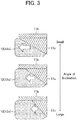
Fig. 3 , the smaller the angle of inclination of theinclined portion 11c becomes, the larger the region which contacts and compresses the elastomer member 12 (thefirst elastomer member 12a) becomes, and the larger input can act as a compressive load in the axially-perpendicular direction (the extending direction of theextended portion 11b of the inner plate 11). And, the larger the angle of inclination of theinclined portion 11c becomes, the smaller the region which contacts and compresses the elastomer member 12 (thefirst elastomer member 12a) becomes, and the smaller input can act as a compressive load in the axially-perpendicular direction (the extending direction of theextended portion 11b of the inner plate 11). - Therefore, the extent of the compressive load which acts on the elastomer member 12 (the
first elastomer member 12a and thesecond elastomer member 12b) in the axially-perpendicular direction (the extending direction of theextended portion 11b of the inner plate) can be changed by suitably changing the angle of inclination of theinclined portion 11c. Thereby, the precompressed status in the elastomer member 12 (thefirst elastomer member 12a and thesecond elastomer member 12b) can be properly changed, and the elastic force (spring constant) which the elastomer member 12 (thefirst elastomer member 12a and thesecond elastomer member 12b) generates can be arbitrarily changed. - In the above-mentioned embodiment and the above-mentioned first modification, the
inclined portion 11c was formed around the whole circumference of the annularextended portion 11b of theinner plate 11. In this case, as shown inFig. 4 (a) , it is also possible to form theinclined portion 11c in an arbitrary location on the circumference of the annularextended portion 11b. - Namely, in the location in which the
inclined portion 11c is formed, the elastomer member 12 (thefirst elastomer member 12a and thesecond elastomer member 12b), in a status that they are clamping theinclined portion 11c, is compressed. Thereby, as mentioned above, a compressive load in the axially-perpendicular direction (the extending direction of theextended portion 11b of the inner plate 11) acts on the elastomer member 12 (thefirst elastomer member 12a and thesecond elastomer member 12b) by theinclined portion 11c. On the other hand, in the location in which theinclined portion 11c ist not formed, in other words, the angle of inclination is set to "0", the elastomer member 12 (thefirst elastomer member 12a and thesecond elastomer member 12b), in a status that they are clamping theextended portion 11b, is compressed. Thereby, a compressive load acts on the elastomer member 12 (thefirst elastomer member 12a and thesecond elastomer member 12b) only in the axial direction, like the above-mentioned specimen for reference. That is, in this case, the location (direction) in which a compressive load acts on the elastomer member 12 (thefirst elastomer member 12a and thesecond elastomer member 12b) in the axial direction and the axially-perpendicular direction (the extending direction of theextended portion 11b of the inner plate 11) and the location (direction) in which a compressive load act thereon only in the axial direction can be distinguished. - Moreover, the angle of inclination of the
inclined portion 11c can be changed, like the above-mentioned first modification. In this case, as shown inFig. 4 (b) , it is also possible to form theinclined portion 11c in an arbitrary location on the circumference of the annularextended portion 11b (including the case where theinclined portion 11c is formed around the whole circumference) and continuously change the angle of inclination of thisinclined portion 11c in the circumference direction. - Namely, in the location in which the
inclined portion 11c is formed, the elastomer member 12 (thefirst elastomer member 12a and thesecond elastomer member 12b) is compressed, in a status that they are clamping theinclined portion 11c with its angle of inclination changes continuously. For this reason, theinclined portion 11c makes the compressive load whose extent changes continuously in the circumference direction act on the elastomer member 12 (thefirst elastomer member 12a and thesecond elastomer member 12b) in the axial direction and the axially-perpendicular direction (the extending direction of theextended portion 11b of the inner plate 11), respectively. On the other hand, in the location in which theinclined portion 11c is not formed, in other words, the angle of inclination is set to "0", the elastomer member 12 (thefirst elastomer member 12a and thesecond elastomer member 12b) in a status that they are clamping theextended portion 11b is compressed. For this reason, a compressive load acts on the elastomer member 12 (thefirst elastomer member 12a and thesecond elastomer member 12b) only in the axial direction. Namely, in this case, the compressive load which continuously changes in the axial direction and the axially-perpendicular direction (the extending direction of theextended portion 11b of the inner plate 11) can act on the elastomer member 12 (thefirst elastomer member 12a and thesecond elastomer member 12b). - Therefore, also in accordance with these, the precompressed status in the elastomer member 12 (the
first elastomer member 12a and thesecond elastomer member 12b) can be properly changed for every locations (every directions), and the elastic force (spring constant) which the elastomer member 12 (thefirst elastomer member 12a and thesecond elastomer member 12b) generates can be arbitrarily changed. Other effects are the same as the above-mentioned embodiment and the above-mentioned first modification. - In the above-mentioned embodiment and the above-mentioned first and second modifications, the
inclined portion 11c which constitutes a compressing means is formed on both the back and front sides opposed to both thefirst elastomer member 12a and thesecond elastomer member 12b of theextended portion 11b of theinner plate 11. In this case, depending on the characteristic demanded, as shown inFig. 5 (a) , for example, in theextended portion 11b of theinner plate 11, it is also possible to form theinclined portion 11c only on one side opposed to thefirst elastomer member 12a. That is, in this case, the compressive load in the axial direction and the axially-perpendicular direction (the extending direction of theextended portion 11b of the inner plate 11) can act only on thefirst elastomer member 12a. Alternatively, as shown inFig. 5 (b) , in theextended portion 11b of theinner plate 11, it is also possible to form theinclined portion 11c only on the one side opposed to thesecond elastomer member 12b. That is, in this case, the compressive load in the axial direction and the axially-perpendicular direction (the extending direction of theextended portion 11b of the inner plate 11) can act only on thesecond elastomer member 12b. - By the way, when the
inclined portion 11c which is formed on theextended portion 11b of theinner plate 11 is formed to be thus opposed to only one of thefirst elastomer member 12a and thesecond elastomer members 12b, there is a possibility that the elastic force (spring constant) generated in the axially-perpendicular direction of the inner plate 11 (more particularly, the shock absorber A connected therewith) (the extending direction of theextended portion 11b of the inner plate 11) may become small as compared with that in the above-mentioned embodiment and the first and second modifications. Therefore, in this case, it is also possible to form the lower case side inclinedportion 13d as a case member side inclined portion or the upper case side inclinedportion 14b as a plate member side inclined portion on the bottominner surface 13b of thelower case 13 or thecompression surface 14a of theupper plate 14, and to constitute a pressing measure including these lower case side-inclined portions 13d or (and) upper case side inclinedportion 14b. - Specifically, in the
extended portion 11b of theinner plate 11, when forming theinclined portion 11c only on one side opposed to thefirst elastomer member 12a, in other words, only on one side opposed to the bottominner surface 13b of thelower case 13, the lower case side inclinedportion 13d can be formed on the bottominner surface 13b of thelower case 13, as shown inFig. 6 (a) . This lower case side inclinedportion 13d is formed in a tapered shape, around the whole circumference of the bottominner surface 13b of thelower case 13, with a thickness increasing towards the outer edge of theextended portion 11b in the extending direction of theextended portion 11b of theinner plate 11, i.e., outwards in a radial direction from the center of the bottominner surface 13b of thelower case 13. Thus, by forming the lower case side inclinedportion 13d in addition to that formation of theinclined portion 11c on theextended portion 11b so as to be opposed to thefirst elastomer member 12a, the elastic force (spring constant) generated in the axially-perpendicular direction (the extending direction of theextended portion 11b of the inner plate 11) can be effectively increased. - Moreover, in the
extended portion 11b of theinner plate 11, when forming theinclined portion 11c only on one side opposed to thesecond elastomer member 12b, in other words, only on one side opposed to thecompression surface 14a of theupper plate 14, the upper plate side inclinedportion 14b can be formed on thecompression surface 14a of theupper plate 14, as shown inFig. 6 (b) . This upper plate side inclinedportion 14b is formed in a tapered shape, around the whole circumference of thecompression surface 14a of theupper plate 14, with a thickness increasing towards the outer edge of theextended portion 11b in the extending direction of theextended portion 11b of theinner plate 11, i.e., outwards in a radial direction from the center of thecompression surface 14a of theupper plate 14. Thus, by forming the upper plate side inclinedportion 14b in addition to that formation of theinclined portion 11c on theextended portion 11b so as to be opposed to thesecond elastomer member 12b, the elastic force (spring constant) generated in the axially-perpendicular direction (the extending direction of theextended portion 11b of the inner plate 11) can be effectively increased. - Therefore, also in this third modification, the same effects as those of the above-mentioned embodiment and the above-mentioned first and second modifications can be expected. In addition, as for the lower case side inclined
portion 13d or the upper plate side inclinedportion 14b formed in accordance with this third modification, similarly to the above-mentioned second modification, it is also possible to form in an arbitrary location on the circumference of the circular bottominner surface 13b of thelower case 13 or thecircular compression surface 14b of theupper plate 14, as shown inFig. 7 (a) , for example., Moreover, as for the angle of inclination of the lower case side inclinedportion 13d or the upper plate side inclinedportion 14b, similarly to the above-mentioned first and second modifications, it is also possible to form the lower case side inclinedportion 13d or the upper plate side-inclined portion 14b in an arbitrary location on the circumference and to continuously change the angle of inclination of these lower case side inclinedportions 13d or the upper plate side inclinedportion 14b in the circumference direction, as shown inFig. 7 (b) , for example. - Also in accordance with these, the precompressed status in the elastomer member 12 (the
first elastomer member 12a and thesecond elastomer member 12b) can be properly changed for every locations (every directions). Therefore, the elastic force (spring constant) which the elastomer member 12 (thefirst elastomer member 12a and thesecond elastomer member 12b) generates can be arbitrarily changed. - Implementation of the present invention is not limited to the above-mentioned embodiment and each modification, and various modifications are possible, unless it deviates from the objectives of the present invention.
- For example, in the above-mentioned embodiment, the
inclined portion 11c was formed on both back and front sides of theextended portion 11b of theinner plate 11. In this case, it is also possible to further form the lower case side inclinedportion 13d on the bottominner surface 13b of thelower case 13, or to further form the upper plate side inclinedportion 14b on thecompression surface 14a of theupper plate 14. Moreover, in the above-mentioned third modification, corresponding to theinclined portion 11c formed on theextended portion 11b of theinner plate 11, the lower case side inclinedportion 13d or the upper plate side inclinedportion 14b was formed. In this case, it is also possible to form the upper plate side inclinedportion 14b or the lower case side inclinedportion 13d also on the side where theinclined portion 11c is not formed. - Also in these cases, the elastomer member 12 (the
first elastomer member 12a and thesecond elastomer member 12b) can be precompressed by generating a compressive load also in the axially-predetermined direction while generating a compressive load in the axial direction. Thereby, when the shock absorber A connected with the vehicle body B through thesuspension mount 10 is displaced in the up-and-down, left-and-right and front-and-rear directions of the vehicle, a desired elastic force can be given with a sufficient responsibility, a displacement of the shock absorber A can be properly controlled, and a desired characteristic can be demonstrated.
Claims (9)
- A suspension mount (10) which connects with a vehicle body (13) a suspension member (A) constituting a suspension mechanism of the vehicle, wherein said suspension mount (10) comprises:an inside member (11) connected with said suspension member (A),an expandable resin elastomer (12) which clamps an extended portion (11b) formed of an expandable resin and extended from said inside member (11),a case member (13) which has a containing portion (13a) for integrally containing said inside member (11) and said expandable resin elastomer (12),a plate member (14) which is integrally adhered to an opening end of said case member (13) and has a compression surface (14a) for compressing said expandable resin elastomer (12) contained inside of said containing portion (13a) of said case member (13), along with a bottom inner surface (13b) of said case member (13), in a status that said expandable resin elastomer (12) clasps said extended portion (11b) of said inside member (11), anda compressing means (11c, 13d, 14b) for compressing said expandable resin elastomer (12) in an extending direction of said extended portion (11b) of said inside member (11) in association with the compression of said expandable resin elastomer (12) by said bottom inner surface (13b) of said case member (13) and said compression surface (14a) of said plate member (14),characterized in thatan inclined portion (11c) which constitutes the compressing means (11c, 13d, 14b) is integrally formed in the extended portion (11b) of the inside member (11).
- The suspension mount (10) according to Claim 1, wherein:
said inclined portion (11c) is formed at least on one side of clamped surfaces of said extended portion (11b) of said inside member (11), which are clamped by said expandable resin elastomer (12). - The suspension mount (10) according to Claim 2, wherein:
said inclined portion (11c) is formed so that its thickness becomes thinner towards the outer edge of said extended portion (11b) in an extending direction of said extended portion (11b). - The suspension mount (10) according to Claim 2 or Claim 3, wherein:in a case where said inclined portion (11c) is formed at least on the clamped surface opposed to said compression surface (14a) of said plate member (14) among said clamped surfaces of said extended portion (11b),said compressing means is configured to further comprise a plate member side inclined portion (14b) formed on said compression surface (14a) of said plate member (14).
- The suspension mount (10) according to Claim 4, wherein:
said plate member side inclined portion (14b) is formed so that its thickness becomes thicker towards the outer edge of said extended portion (11b) in an extending direction of said extended portion (11b). - The suspension mount (10) according to any one of Claims 2 to 5, wherein:in a case where said inclined portion (11c) is formed at least on the clamped surface opposed to said bottom inner surface (13b) of said case member (13) among said clamped surfaces of said extended portion (11b),said compressing means is configured to further comprise a case member side inclined portion (13d) formed on said bottom inner surface (13b) of said case member (13).
- The suspension mount (10) according to Claim 6, wherein:
said case member side inclined portion (13d) is formed so that its thickness becomes thicker towards the outer edge of said extended portion (11b), to which said case member side inclined portion (13d) is opposed, in an extending direction of said extended portion (11b). - The suspension mount (10) according to any one of Claims 1 to 7, wherein:
said compressing means (11c, 13d, 14b) compresses said expandable resin elastomer (12) to different compression states along the circumference direction of said inside member (11). - The suspension mount (10) according to any one of Claims 1 to 8, wherein:
said suspension member is a shock absorber (A) and said inside member (11) is connected with an absorber rod (R) of the shock absorber (A).
Applications Claiming Priority (2)
| Application Number | Priority Date | Filing Date | Title |
|---|---|---|---|
| JP2013021110A JP5786876B2 (en) | 2013-02-06 | 2013-02-06 | Suspension mount |
| PCT/JP2013/082601 WO2014122842A1 (en) | 2013-02-06 | 2013-12-04 | Suspension mount |
Publications (3)
| Publication Number | Publication Date |
|---|---|
| EP2955409A1 EP2955409A1 (en) | 2015-12-16 |
| EP2955409A4 EP2955409A4 (en) | 2016-04-27 |
| EP2955409B1 true EP2955409B1 (en) | 2020-02-26 |
Family
ID=51299448
Family Applications (1)
| Application Number | Title | Priority Date | Filing Date |
|---|---|---|---|
| EP13874462.8A Active EP2955409B1 (en) | 2013-02-06 | 2013-12-04 | Suspension mount |
Country Status (5)
| Country | Link |
|---|---|
| US (1) | US9452651B2 (en) |
| EP (1) | EP2955409B1 (en) |
| JP (1) | JP5786876B2 (en) |
| CN (1) | CN104981625B (en) |
| WO (1) | WO2014122842A1 (en) |
Families Citing this family (5)
| Publication number | Priority date | Publication date | Assignee | Title |
|---|---|---|---|---|
| US10427488B2 (en) * | 2016-10-13 | 2019-10-01 | ClearMotion, Inc. | Method and apparatus for mitigating static loads in components connecting multiple structures |
| WO2019074026A1 (en) * | 2017-10-10 | 2019-04-18 | 株式会社ブリヂストン | Active damper upper mount |
| US20190161141A1 (en) | 2017-11-29 | 2019-05-30 | Ryan D. Aberle | Snowmobile ski dampener |
| CN110588268B (en) * | 2018-06-12 | 2023-02-24 | 上海凯众材料科技股份有限公司 | Upper support of shock absorber |
| US11884359B2 (en) | 2022-02-25 | 2024-01-30 | Sram, Llc | Bicycle suspension components |
Family Cites Families (22)
| Publication number | Priority date | Publication date | Assignee | Title |
|---|---|---|---|---|
| FR2319813A1 (en) * | 1975-08-01 | 1977-02-25 | Renault | Shock absorber bushing on motor vehicle - is prestressed by expanding inner bush and reducing face angles to eliminate static moulding stess |
| JPS55140607A (en) * | 1979-04-18 | 1980-11-04 | Nissan Motor Co Ltd | Strut-type suspender |
| US4828232A (en) * | 1983-11-14 | 1989-05-09 | General Motors Corporation | Vehicle air suspension strut with compliant cover plate assembly |
| JPS6126613U (en) * | 1984-07-24 | 1986-02-17 | トヨタ自動車株式会社 | Air spring suspension bushing assembly |
| JPH0662241U (en) * | 1993-02-05 | 1994-09-02 | 株式会社ショーワ | Mounting structure for mounting mount of shock absorber |
| JP3168856B2 (en) * | 1995-02-07 | 2001-05-21 | 三菱自動車工業株式会社 | Strut mount mounting structure |
| DE29900342U1 (en) * | 1999-01-12 | 1999-04-08 | Daimler Chrysler Ag | Support bearing for the angularly movable, elastic support of a piston rod from a shock absorber on the vehicle body |
| JP2001347814A (en) * | 2000-06-05 | 2001-12-18 | Toyo Tire & Rubber Co Ltd | Suspension support |
| JP2002021867A (en) * | 2000-07-04 | 2002-01-23 | Minebea Co Ltd | Fixing structure for upper mount spherical bearing |
| NO20021215A (en) * | 2002-03-12 | 2003-07-28 | Kongsberg Automotive Asa | Coupling |
| US7178795B2 (en) * | 2003-12-23 | 2007-02-20 | Basf Corporation | Mounting assembly for a vehicle suspension component |
| DE102004003132A1 (en) * | 2004-01-15 | 2005-08-11 | Dr.Ing.H.C. F. Porsche Ag | Bearing for a damper element of a vehicle |
| JP3844002B2 (en) * | 2005-01-12 | 2006-11-08 | 東洋ゴム工業株式会社 | Strut mount |
| JP4841923B2 (en) * | 2005-10-06 | 2011-12-21 | 株式会社ブリヂストン | Strut mount |
| US7347414B2 (en) * | 2006-06-30 | 2008-03-25 | Ford Global Technologies, Llc | Integrated vehicle shock absorber mount and jounce bumper |
| DE102007026471B4 (en) * | 2007-06-05 | 2009-01-22 | Zf Friedrichshafen Ag | Suspension strut |
| JP2010090995A (en) | 2008-10-08 | 2010-04-22 | Bridgestone Corp | Strut mount |
| JP5290875B2 (en) | 2009-06-05 | 2013-09-18 | 株式会社ブリヂストン | Strut mount |
| JP5015309B2 (en) * | 2009-11-24 | 2012-08-29 | ヤマハ発動機株式会社 | Hydraulic shock absorber for vehicles |
| JP5490566B2 (en) * | 2010-02-25 | 2014-05-14 | 東洋ゴム工業株式会社 | Suspension support |
| JP5400980B1 (en) * | 2013-03-29 | 2014-01-29 | 株式会社ショーワ | Suspension device, suspension support, and cushioning member |
| US8960696B2 (en) * | 2013-04-16 | 2015-02-24 | Zhongli North America Inc. | Strut top mount with MCU and integral travel limiter |
-
2013
- 2013-02-06 JP JP2013021110A patent/JP5786876B2/en active Active
- 2013-12-04 EP EP13874462.8A patent/EP2955409B1/en active Active
- 2013-12-04 CN CN201380072461.3A patent/CN104981625B/en not_active Expired - Fee Related
- 2013-12-04 US US14/764,462 patent/US9452651B2/en active Active
- 2013-12-04 WO PCT/JP2013/082601 patent/WO2014122842A1/en active Application Filing
Non-Patent Citations (1)
| Title |
|---|
| None * |
Also Published As
| Publication number | Publication date |
|---|---|
| CN104981625B (en) | 2017-03-08 |
| EP2955409A1 (en) | 2015-12-16 |
| JP5786876B2 (en) | 2015-09-30 |
| WO2014122842A1 (en) | 2014-08-14 |
| CN104981625A (en) | 2015-10-14 |
| JP2014152821A (en) | 2014-08-25 |
| US20150367699A1 (en) | 2015-12-24 |
| EP2955409A4 (en) | 2016-04-27 |
| US9452651B2 (en) | 2016-09-27 |
Similar Documents
| Publication | Publication Date | Title |
|---|---|---|
| EP2955409B1 (en) | Suspension mount | |
| US8939437B2 (en) | Anti-vibration device | |
| JP5906251B2 (en) | Mounting structure for vehicle damper | |
| US9739338B2 (en) | Vibration- damping support device | |
| US20050133325A1 (en) | Dynamic damper | |
| US20130161888A1 (en) | Jounce bumper | |
| CA2976751C (en) | Lower-side spring-receiving member | |
| JP5804252B2 (en) | Grommet | |
| US20080136076A1 (en) | Jounce Bumper Assembly | |
| JP6681189B2 (en) | Upper support with cushion body | |
| US20150300445A1 (en) | Vibration damping device | |
| JP2020012527A (en) | Cab mount | |
| JP3627527B2 (en) | Cylindrical anti-vibration mount | |
| US20190048956A1 (en) | Vibration damping device | |
| JPH06280913A (en) | Spring seat rubber | |
| CN116928284A (en) | Cylindrical support | |
| JP7374754B2 (en) | Vibration isolator | |
| KR101162304B1 (en) | Air suspension apparatus | |
| CN215908305U (en) | Automobile rear shock absorber and vehicle with same | |
| JP2002021931A (en) | Member mount | |
| KR101131044B1 (en) | Air suspension apparatus | |
| GB2579245A (en) | Vibrating flange assembly | |
| JP6562663B2 (en) | Vibration isolator | |
| JPS6230924B2 (en) | ||
| JP2019065988A (en) | Vibration control device |
Legal Events
| Date | Code | Title | Description |
|---|---|---|---|
| PUAI | Public reference made under article 153(3) epc to a published international application that has entered the european phase |
Free format text: ORIGINAL CODE: 0009012 |
|
| 17P | Request for examination filed |
Effective date: 20150820 |
|
| AK | Designated contracting states |
Kind code of ref document: A1 Designated state(s): AL AT BE BG CH CY CZ DE DK EE ES FI FR GB GR HR HU IE IS IT LI LT LU LV MC MK MT NL NO PL PT RO RS SE SI SK SM TR |
|
| AX | Request for extension of the european patent |
Extension state: BA ME |
|
| A4 | Supplementary search report drawn up and despatched |
Effective date: 20160331 |
|
| RIC1 | Information provided on ipc code assigned before grant |
Ipc: B60G 13/00 20060101ALI20160323BHEP Ipc: F16F 9/54 20060101AFI20160323BHEP Ipc: B60G 15/06 20060101ALI20160323BHEP Ipc: F16F 15/08 20060101ALI20160323BHEP Ipc: B60G 15/08 20060101ALI20160323BHEP Ipc: F16F 1/44 20060101ALI20160323BHEP |
|
| DAX | Request for extension of the european patent (deleted) | ||
| STAA | Information on the status of an ep patent application or granted ep patent |
Free format text: STATUS: EXAMINATION IS IN PROGRESS |
|
| 17Q | First examination report despatched |
Effective date: 20181128 |
|
| GRAP | Despatch of communication of intention to grant a patent |
Free format text: ORIGINAL CODE: EPIDOSNIGR1 |
|
| STAA | Information on the status of an ep patent application or granted ep patent |
Free format text: STATUS: GRANT OF PATENT IS INTENDED |
|
| INTG | Intention to grant announced |
Effective date: 20190826 |
|
| GRAS | Grant fee paid |
Free format text: ORIGINAL CODE: EPIDOSNIGR3 |
|
| GRAA | (expected) grant |
Free format text: ORIGINAL CODE: 0009210 |
|
| STAA | Information on the status of an ep patent application or granted ep patent |
Free format text: STATUS: THE PATENT HAS BEEN GRANTED |
|
| AK | Designated contracting states |
Kind code of ref document: B1 Designated state(s): AL AT BE BG CH CY CZ DE DK EE ES FI FR GB GR HR HU IE IS IT LI LT LU LV MC MK MT NL NO PL PT RO RS SE SI SK SM TR |
|
| REG | Reference to a national code |
Ref country code: GB Ref legal event code: FG4D |
|
| REG | Reference to a national code |
Ref country code: CH Ref legal event code: EP |
|
| REG | Reference to a national code |
Ref country code: DE Ref legal event code: R096 Ref document number: 602013066334 Country of ref document: DE |
|
| REG | Reference to a national code |
Ref country code: AT Ref legal event code: REF Ref document number: 1238001 Country of ref document: AT Kind code of ref document: T Effective date: 20200315 |
|
| REG | Reference to a national code |
Ref country code: IE Ref legal event code: FG4D |
|
| PG25 | Lapsed in a contracting state [announced via postgrant information from national office to epo] |
Ref country code: NO Free format text: LAPSE BECAUSE OF FAILURE TO SUBMIT A TRANSLATION OF THE DESCRIPTION OR TO PAY THE FEE WITHIN THE PRESCRIBED TIME-LIMIT Effective date: 20200526 Ref country code: FI Free format text: LAPSE BECAUSE OF FAILURE TO SUBMIT A TRANSLATION OF THE DESCRIPTION OR TO PAY THE FEE WITHIN THE PRESCRIBED TIME-LIMIT Effective date: 20200226 Ref country code: RS Free format text: LAPSE BECAUSE OF FAILURE TO SUBMIT A TRANSLATION OF THE DESCRIPTION OR TO PAY THE FEE WITHIN THE PRESCRIBED TIME-LIMIT Effective date: 20200226 |
|
| REG | Reference to a national code |
Ref country code: NL Ref legal event code: MP Effective date: 20200226 |
|
| REG | Reference to a national code |
Ref country code: LT Ref legal event code: MG4D |
|
| PG25 | Lapsed in a contracting state [announced via postgrant information from national office to epo] |
Ref country code: GR Free format text: LAPSE BECAUSE OF FAILURE TO SUBMIT A TRANSLATION OF THE DESCRIPTION OR TO PAY THE FEE WITHIN THE PRESCRIBED TIME-LIMIT Effective date: 20200527 Ref country code: IS Free format text: LAPSE BECAUSE OF FAILURE TO SUBMIT A TRANSLATION OF THE DESCRIPTION OR TO PAY THE FEE WITHIN THE PRESCRIBED TIME-LIMIT Effective date: 20200626 Ref country code: HR Free format text: LAPSE BECAUSE OF FAILURE TO SUBMIT A TRANSLATION OF THE DESCRIPTION OR TO PAY THE FEE WITHIN THE PRESCRIBED TIME-LIMIT Effective date: 20200226 Ref country code: BG Free format text: LAPSE BECAUSE OF FAILURE TO SUBMIT A TRANSLATION OF THE DESCRIPTION OR TO PAY THE FEE WITHIN THE PRESCRIBED TIME-LIMIT Effective date: 20200526 Ref country code: SE Free format text: LAPSE BECAUSE OF FAILURE TO SUBMIT A TRANSLATION OF THE DESCRIPTION OR TO PAY THE FEE WITHIN THE PRESCRIBED TIME-LIMIT Effective date: 20200226 Ref country code: LV Free format text: LAPSE BECAUSE OF FAILURE TO SUBMIT A TRANSLATION OF THE DESCRIPTION OR TO PAY THE FEE WITHIN THE PRESCRIBED TIME-LIMIT Effective date: 20200226 |
|
| PG25 | Lapsed in a contracting state [announced via postgrant information from national office to epo] |
Ref country code: NL Free format text: LAPSE BECAUSE OF FAILURE TO SUBMIT A TRANSLATION OF THE DESCRIPTION OR TO PAY THE FEE WITHIN THE PRESCRIBED TIME-LIMIT Effective date: 20200226 |
|
| PG25 | Lapsed in a contracting state [announced via postgrant information from national office to epo] |
Ref country code: PT Free format text: LAPSE BECAUSE OF FAILURE TO SUBMIT A TRANSLATION OF THE DESCRIPTION OR TO PAY THE FEE WITHIN THE PRESCRIBED TIME-LIMIT Effective date: 20200719 Ref country code: LT Free format text: LAPSE BECAUSE OF FAILURE TO SUBMIT A TRANSLATION OF THE DESCRIPTION OR TO PAY THE FEE WITHIN THE PRESCRIBED TIME-LIMIT Effective date: 20200226 Ref country code: CZ Free format text: LAPSE BECAUSE OF FAILURE TO SUBMIT A TRANSLATION OF THE DESCRIPTION OR TO PAY THE FEE WITHIN THE PRESCRIBED TIME-LIMIT Effective date: 20200226 Ref country code: ES Free format text: LAPSE BECAUSE OF FAILURE TO SUBMIT A TRANSLATION OF THE DESCRIPTION OR TO PAY THE FEE WITHIN THE PRESCRIBED TIME-LIMIT Effective date: 20200226 Ref country code: DK Free format text: LAPSE BECAUSE OF FAILURE TO SUBMIT A TRANSLATION OF THE DESCRIPTION OR TO PAY THE FEE WITHIN THE PRESCRIBED TIME-LIMIT Effective date: 20200226 Ref country code: EE Free format text: LAPSE BECAUSE OF FAILURE TO SUBMIT A TRANSLATION OF THE DESCRIPTION OR TO PAY THE FEE WITHIN THE PRESCRIBED TIME-LIMIT Effective date: 20200226 Ref country code: SK Free format text: LAPSE BECAUSE OF FAILURE TO SUBMIT A TRANSLATION OF THE DESCRIPTION OR TO PAY THE FEE WITHIN THE PRESCRIBED TIME-LIMIT Effective date: 20200226 Ref country code: RO Free format text: LAPSE BECAUSE OF FAILURE TO SUBMIT A TRANSLATION OF THE DESCRIPTION OR TO PAY THE FEE WITHIN THE PRESCRIBED TIME-LIMIT Effective date: 20200226 Ref country code: SM Free format text: LAPSE BECAUSE OF FAILURE TO SUBMIT A TRANSLATION OF THE DESCRIPTION OR TO PAY THE FEE WITHIN THE PRESCRIBED TIME-LIMIT Effective date: 20200226 |
|
| REG | Reference to a national code |
Ref country code: AT Ref legal event code: MK05 Ref document number: 1238001 Country of ref document: AT Kind code of ref document: T Effective date: 20200226 |
|
| REG | Reference to a national code |
Ref country code: DE Ref legal event code: R097 Ref document number: 602013066334 Country of ref document: DE |
|
| PLBE | No opposition filed within time limit |
Free format text: ORIGINAL CODE: 0009261 |
|
| STAA | Information on the status of an ep patent application or granted ep patent |
Free format text: STATUS: NO OPPOSITION FILED WITHIN TIME LIMIT |
|
| PG25 | Lapsed in a contracting state [announced via postgrant information from national office to epo] |
Ref country code: IT Free format text: LAPSE BECAUSE OF FAILURE TO SUBMIT A TRANSLATION OF THE DESCRIPTION OR TO PAY THE FEE WITHIN THE PRESCRIBED TIME-LIMIT Effective date: 20200226 Ref country code: AT Free format text: LAPSE BECAUSE OF FAILURE TO SUBMIT A TRANSLATION OF THE DESCRIPTION OR TO PAY THE FEE WITHIN THE PRESCRIBED TIME-LIMIT Effective date: 20200226 |
|
| 26N | No opposition filed |
Effective date: 20201127 |
|
| PG25 | Lapsed in a contracting state [announced via postgrant information from national office to epo] |
Ref country code: PL Free format text: LAPSE BECAUSE OF FAILURE TO SUBMIT A TRANSLATION OF THE DESCRIPTION OR TO PAY THE FEE WITHIN THE PRESCRIBED TIME-LIMIT Effective date: 20200226 Ref country code: SI Free format text: LAPSE BECAUSE OF FAILURE TO SUBMIT A TRANSLATION OF THE DESCRIPTION OR TO PAY THE FEE WITHIN THE PRESCRIBED TIME-LIMIT Effective date: 20200226 |
|
| REG | Reference to a national code |
Ref country code: CH Ref legal event code: PL |
|
| GBPC | Gb: european patent ceased through non-payment of renewal fee |
Effective date: 20201204 |
|
| PG25 | Lapsed in a contracting state [announced via postgrant information from national office to epo] |
Ref country code: MC Free format text: LAPSE BECAUSE OF FAILURE TO SUBMIT A TRANSLATION OF THE DESCRIPTION OR TO PAY THE FEE WITHIN THE PRESCRIBED TIME-LIMIT Effective date: 20200226 |
|
| REG | Reference to a national code |
Ref country code: BE Ref legal event code: MM Effective date: 20201231 |
|
| REG | Reference to a national code |
Ref country code: DE Ref legal event code: R084 Ref document number: 602013066334 Country of ref document: DE |
|
| PG25 | Lapsed in a contracting state [announced via postgrant information from national office to epo] |
Ref country code: IE Free format text: LAPSE BECAUSE OF NON-PAYMENT OF DUE FEES Effective date: 20201204 Ref country code: LU Free format text: LAPSE BECAUSE OF NON-PAYMENT OF DUE FEES Effective date: 20201204 Ref country code: FR Free format text: LAPSE BECAUSE OF NON-PAYMENT OF DUE FEES Effective date: 20201231 |
|
| PG25 | Lapsed in a contracting state [announced via postgrant information from national office to epo] |
Ref country code: LI Free format text: LAPSE BECAUSE OF NON-PAYMENT OF DUE FEES Effective date: 20201231 Ref country code: CH Free format text: LAPSE BECAUSE OF NON-PAYMENT OF DUE FEES Effective date: 20201231 Ref country code: GB Free format text: LAPSE BECAUSE OF NON-PAYMENT OF DUE FEES Effective date: 20201204 |
|
| PGFP | Annual fee paid to national office [announced via postgrant information from national office to epo] |
Ref country code: DE Payment date: 20211102 Year of fee payment: 9 |
|
| PG25 | Lapsed in a contracting state [announced via postgrant information from national office to epo] |
Ref country code: TR Free format text: LAPSE BECAUSE OF FAILURE TO SUBMIT A TRANSLATION OF THE DESCRIPTION OR TO PAY THE FEE WITHIN THE PRESCRIBED TIME-LIMIT Effective date: 20200226 Ref country code: MT Free format text: LAPSE BECAUSE OF FAILURE TO SUBMIT A TRANSLATION OF THE DESCRIPTION OR TO PAY THE FEE WITHIN THE PRESCRIBED TIME-LIMIT Effective date: 20200226 Ref country code: CY Free format text: LAPSE BECAUSE OF FAILURE TO SUBMIT A TRANSLATION OF THE DESCRIPTION OR TO PAY THE FEE WITHIN THE PRESCRIBED TIME-LIMIT Effective date: 20200226 |
|
| PG25 | Lapsed in a contracting state [announced via postgrant information from national office to epo] |
Ref country code: MK Free format text: LAPSE BECAUSE OF FAILURE TO SUBMIT A TRANSLATION OF THE DESCRIPTION OR TO PAY THE FEE WITHIN THE PRESCRIBED TIME-LIMIT Effective date: 20200226 Ref country code: AL Free format text: LAPSE BECAUSE OF FAILURE TO SUBMIT A TRANSLATION OF THE DESCRIPTION OR TO PAY THE FEE WITHIN THE PRESCRIBED TIME-LIMIT Effective date: 20200226 |
|
| PG25 | Lapsed in a contracting state [announced via postgrant information from national office to epo] |
Ref country code: BE Free format text: LAPSE BECAUSE OF NON-PAYMENT OF DUE FEES Effective date: 20201231 |
|
| REG | Reference to a national code |
Ref country code: DE Ref legal event code: R119 Ref document number: 602013066334 Country of ref document: DE |
|
| PG25 | Lapsed in a contracting state [announced via postgrant information from national office to epo] |
Ref country code: DE Free format text: LAPSE BECAUSE OF NON-PAYMENT OF DUE FEES Effective date: 20230701 |