EP2955036A1 - Pneumatic tire - Google Patents
Pneumatic tire Download PDFInfo
- Publication number
- EP2955036A1 EP2955036A1 EP14748799.5A EP14748799A EP2955036A1 EP 2955036 A1 EP2955036 A1 EP 2955036A1 EP 14748799 A EP14748799 A EP 14748799A EP 2955036 A1 EP2955036 A1 EP 2955036A1
- Authority
- EP
- European Patent Office
- Prior art keywords
- tire
- lateral groove
- groove
- grooves
- lateral
- Prior art date
- Legal status (The legal status is an assumption and is not a legal conclusion. Google has not performed a legal analysis and makes no representation as to the accuracy of the status listed.)
- Granted
Links
- XLYOFNOQVPJJNP-UHFFFAOYSA-N water Substances O XLYOFNOQVPJJNP-UHFFFAOYSA-N 0.000 description 15
- 230000000694 effects Effects 0.000 description 3
- 230000015572 biosynthetic process Effects 0.000 description 2
- 230000007423 decrease Effects 0.000 description 2
- 238000005452 bending Methods 0.000 description 1
- 238000005096 rolling process Methods 0.000 description 1
- 238000006748 scratching Methods 0.000 description 1
Images

Classifications
-
- B—PERFORMING OPERATIONS; TRANSPORTING
- B60—VEHICLES IN GENERAL
- B60C—VEHICLE TYRES; TYRE INFLATION; TYRE CHANGING; CONNECTING VALVES TO INFLATABLE ELASTIC BODIES IN GENERAL; DEVICES OR ARRANGEMENTS RELATED TO TYRES
- B60C11/00—Tyre tread bands; Tread patterns; Anti-skid inserts
- B60C11/03—Tread patterns
- B60C11/04—Tread patterns in which the raised area of the pattern consists only of continuous circumferential ribs, e.g. zig-zag
-
- B—PERFORMING OPERATIONS; TRANSPORTING
- B60—VEHICLES IN GENERAL
- B60C—VEHICLE TYRES; TYRE INFLATION; TYRE CHANGING; CONNECTING VALVES TO INFLATABLE ELASTIC BODIES IN GENERAL; DEVICES OR ARRANGEMENTS RELATED TO TYRES
- B60C11/00—Tyre tread bands; Tread patterns; Anti-skid inserts
- B60C11/03—Tread patterns
- B60C11/0302—Tread patterns directional pattern, i.e. with main rolling direction
-
- B—PERFORMING OPERATIONS; TRANSPORTING
- B60—VEHICLES IN GENERAL
- B60C—VEHICLE TYRES; TYRE INFLATION; TYRE CHANGING; CONNECTING VALVES TO INFLATABLE ELASTIC BODIES IN GENERAL; DEVICES OR ARRANGEMENTS RELATED TO TYRES
- B60C11/00—Tyre tread bands; Tread patterns; Anti-skid inserts
- B60C11/03—Tread patterns
- B60C11/0306—Patterns comprising block rows or discontinuous ribs
-
- B—PERFORMING OPERATIONS; TRANSPORTING
- B60—VEHICLES IN GENERAL
- B60C—VEHICLE TYRES; TYRE INFLATION; TYRE CHANGING; CONNECTING VALVES TO INFLATABLE ELASTIC BODIES IN GENERAL; DEVICES OR ARRANGEMENTS RELATED TO TYRES
- B60C11/00—Tyre tread bands; Tread patterns; Anti-skid inserts
- B60C11/03—Tread patterns
- B60C11/11—Tread patterns in which the raised area of the pattern consists only of isolated elements, e.g. blocks
-
- B—PERFORMING OPERATIONS; TRANSPORTING
- B60—VEHICLES IN GENERAL
- B60C—VEHICLE TYRES; TYRE INFLATION; TYRE CHANGING; CONNECTING VALVES TO INFLATABLE ELASTIC BODIES IN GENERAL; DEVICES OR ARRANGEMENTS RELATED TO TYRES
- B60C11/00—Tyre tread bands; Tread patterns; Anti-skid inserts
- B60C11/03—Tread patterns
- B60C11/12—Tread patterns characterised by the use of narrow slits or incisions, e.g. sipes
- B60C11/1259—Depth of the sipe
- B60C11/1263—Depth of the sipe different within the same sipe
-
- B—PERFORMING OPERATIONS; TRANSPORTING
- B60—VEHICLES IN GENERAL
- B60C—VEHICLE TYRES; TYRE INFLATION; TYRE CHANGING; CONNECTING VALVES TO INFLATABLE ELASTIC BODIES IN GENERAL; DEVICES OR ARRANGEMENTS RELATED TO TYRES
- B60C5/00—Inflatable pneumatic tyres or inner tubes
-
- B—PERFORMING OPERATIONS; TRANSPORTING
- B60—VEHICLES IN GENERAL
- B60C—VEHICLE TYRES; TYRE INFLATION; TYRE CHANGING; CONNECTING VALVES TO INFLATABLE ELASTIC BODIES IN GENERAL; DEVICES OR ARRANGEMENTS RELATED TO TYRES
- B60C11/00—Tyre tread bands; Tread patterns; Anti-skid inserts
- B60C11/03—Tread patterns
- B60C2011/0337—Tread patterns characterised by particular design features of the pattern
- B60C2011/0339—Grooves
- B60C2011/0341—Circumferential grooves
- B60C2011/0346—Circumferential grooves with zigzag shape
-
- B—PERFORMING OPERATIONS; TRANSPORTING
- B60—VEHICLES IN GENERAL
- B60C—VEHICLE TYRES; TYRE INFLATION; TYRE CHANGING; CONNECTING VALVES TO INFLATABLE ELASTIC BODIES IN GENERAL; DEVICES OR ARRANGEMENTS RELATED TO TYRES
- B60C11/00—Tyre tread bands; Tread patterns; Anti-skid inserts
- B60C11/03—Tread patterns
- B60C2011/0337—Tread patterns characterised by particular design features of the pattern
- B60C2011/0339—Grooves
- B60C2011/0341—Circumferential grooves
- B60C2011/0351—Shallow grooves, i.e. having a depth of less than 50% of other grooves
-
- B—PERFORMING OPERATIONS; TRANSPORTING
- B60—VEHICLES IN GENERAL
- B60C—VEHICLE TYRES; TYRE INFLATION; TYRE CHANGING; CONNECTING VALVES TO INFLATABLE ELASTIC BODIES IN GENERAL; DEVICES OR ARRANGEMENTS RELATED TO TYRES
- B60C11/00—Tyre tread bands; Tread patterns; Anti-skid inserts
- B60C11/03—Tread patterns
- B60C2011/0337—Tread patterns characterised by particular design features of the pattern
- B60C2011/0386—Continuous ribs
- B60C2011/0388—Continuous ribs provided at the equatorial plane
-
- B—PERFORMING OPERATIONS; TRANSPORTING
- B60—VEHICLES IN GENERAL
- B60C—VEHICLE TYRES; TYRE INFLATION; TYRE CHANGING; CONNECTING VALVES TO INFLATABLE ELASTIC BODIES IN GENERAL; DEVICES OR ARRANGEMENTS RELATED TO TYRES
- B60C11/00—Tyre tread bands; Tread patterns; Anti-skid inserts
- B60C11/03—Tread patterns
- B60C11/12—Tread patterns characterised by the use of narrow slits or incisions, e.g. sipes
- B60C11/1204—Tread patterns characterised by the use of narrow slits or incisions, e.g. sipes with special shape of the sipe
- B60C2011/1213—Tread patterns characterised by the use of narrow slits or incisions, e.g. sipes with special shape of the sipe sinusoidal or zigzag at the tread surface
Definitions
- the disclosure relates to a pneumatic tire, and in particular to a pneumatic tire that can be suitably used as a winter tire.
- Pneumatic tires for use on snow-covered or icy roads that have been conventionally proposed comprise, on a tread, transverse grooves each inclined toward the side opposite the rotation direction and extending from the groove starting point that terminates near the tire equator toward the outer side in the tire width direction; and inclined grooves each crossing at least two of the transverse grooves and extending at a greater angle than the transverse grooves in the same direction as the transverse grooves which the inclined groove has crossed, wherein a center land extending continuously in the tire circumference direction on the tire equator and edge lands disposed on the outsides, in the tire width direction, of the inclined grooves are defined, and a large number of sipes are provided in the center land and the edge lands.
- Patent Literature 1 PTL 1
- the pneumatic tire of the disclosure includes, on a tread surface, a pair of circumferential grooves extending on both sides of a tire equator; a plurality of lateral grooves each extending in a tire width direction between a tread edge and a rib-shaped center land row defined by the pair of circumferential grooves; and longitudinal grooves disposed on the outsides, in the tire width direction, of the circumferential grooves and each communicating between the lateral grooves that are adjacent to each other in a tire circumference direction.
- Each of the lateral grooves includes a lateral groove first portion, a lateral groove second portion disposed further outward, in the tire width direction, than the lateral groove first portion, and a lateral groove step portion connecting the lateral groove first portion and the lateral groove second portion.
- a groove width center of the outer end, in the tire width direction, of the lateral groove first portion is disposed closer to one tire circumferential side than a groove width center of the inner end, in the tire width direction, of the lateral groove second portion.
- the lateral groove step portion extends at an angle relative to the tire circumference direction so as to connect the outer end, in the tire width direction, of the lateral groove first portion and the inner end, in the tire width direction, of the lateral groove second portion.
- the longitudinal grooves extend at an angle relative to the tire circumference direction toward the side opposite the side the lateral groove step portion extends.
- the end portion on the one tire circumferential side of each of the longitudinal grooves joins an area where the lateral groove second portion and the lateral groove step portion of the lateral groove on the one tire circumferential side join together.
- the end portion on the other tire circumferential side of each of the longitudinal grooves joins an area where the lateral groove first portion and the lateral groove step portion of the lateral groove on the other tire circumferential side join together.
- the phrase “extend at an angle relative to the tire circumference direction toward the side opposite the side the lateral groove step portion extends” means that the extending direction of the grooves is inclined, relative to the tire circumference direction, in the direction opposite the direction the lateral groove step portion extends.
- the term “extending direction of the grooves” refers to, when the grooves extend in a bending manner, the direction in which the center line of the amplitude extends.
- Each of the longitudinal grooves preferably includes a longitudinal groove first portion, a longitudinal groove second portion disposed on the one tire circumferential side of the longitudinal groove first portion, and a longitudinal groove step portion connecting the longitudinal first portion and the longitudinal second portion.
- the inclination angle of the longitudinal groove step portion relative to the tire circumference direction is preferably greater than the inclination angles of the longitudinal groove first portion and the longitudinal groove second portion relative to the tire circumference direction.
- the depth of the longitudinal grooves is preferably shallower than the depth of the circumferential grooves.
- the depth of the longitudinal grooves By making the depth of the longitudinal grooves shallower, which is disposed further outward, in the tire width direction, than the circumferential grooves, rigidity reduction of the blocks on the outer side in the tire width direction can be suppressed. Thus, inclination of the blocks can be prevented so that turning performance as well as braking performance can be improved.
- the depth of the longitudinal grooves is made shallow, water flow through the lateral grooves in wet road surface running can be further enhanced, thereby improving drainage performance.
- the lateral groove second portion have a part extending zigzag as seen in a planar view.
- the shoulder portions which is subjected to high pressure in braking, is sufficiently provided with an edge component, so that braking performance can be improved.
- a pneumatic tire that has superior drainage performance while maintaining on-snow and on-ice performances.
- a pneumatic tire 1 includes, on a tread surface, a pair of circumferential grooves 2 extending on both sides of the tire equator C, a plurality of lateral grooves 3 each continuously extending in a tire width direction between a tread edge TE and a rib-shaped center land row CL defined by the pair of circumferential grooves 2, and longitudinal grooves 4 disposed on the outsides of the circumferential grooves 2 in the tire width direction and each communicating between the lateral grooves 3 that are adjacent to each other in a tire circumference direction.
- a middle block row ML On each outside, in the tire width direction, of the center land row CL, a middle block row ML is provided that consists of a plurality of middle blocks each defined by the circumferential groove 2, the longitudinal groove 4, and the lateral grooves 3. Further, on the outside, in the tire width direction, of each middle block row ML, an edge block row EL is provided that consists of a plurality of edge blocks each defined by the longitudinal groove 4, the tread edge TE, and the lateral grooves 3.
- Each of the center land row CL, the middle block row ML, and the edge block row EL includes a plurality of sipes S.
- the sipes S may take any shape.
- the sipes S may be so-what is called three-dimensional sipes or two-dimensional sipes.
- the sipes S may extend in any direction.
- a plurality of sipes S oriented in the tire with direction may be provided in the center land row CL, the middle block row ML, and the edge block row EL so as to increase an edge component in the tire width direction.
- a plurality of sipes S oriented in the tire circumference direction may be provided to increase an edge component in the tire circumference direction.
- the pneumatic tire 1 is a tire with a rotation direction that is specified by known means. In use, the pneumatic tire 1 is fitted to a vehicle to rotate downwardly in FIG. 1 when rotated in a normal direction (i.e., when moving forward).
- the pair of circumferential grooves 2 extending in the tire circumference direction are bent with amplitude in the tire width direction.
- the circumferential grooves 2 have a zigzag shape, or specifically have bends each of which is convex toward the inside in the tire width direction between two lateral grooves 3 that are adjacent to each other in the tire circumference direction.
- each lateral groove 3 extends at an angle relative to the tire width direction. More specifically, the lateral groove 3 extending at an angle is bent twice toward an other tire circumferential side B.
- the lateral grooves 3L, 3L', and 3L" disposed on one side, in the tire width direction, of the tire equator C (i.e., the left side in FIG. 1 ) and the lateral grooves 3R, 3R', and 3R" disposed on the other side, in the tire width direction, of the tire equator C are both arranged in parallel in the tire circumference direction at a constant pitch.
- the positions where the lateral grooves 3L, 3L', and 3L", disposed on one side in the tire width direction, are arranged are half pitch off-set, in the tire circumference direction, from the positions where the lateral grooves 3R, 3R', and 3R", disposed on the other side in the tire width direction, are arranged.
- Each lateral groove 3 includes a lateral groove first portion 31, a lateral groove second portion 32 disposed further outward, in the tire width direction, than the lateral groove first portion 31, and a lateral groove step portion 33 that connects the lateral groove first portion 31 and the lateral groove second portion 32.
- the lateral groove first portion 31 extends to form a curve that is convex toward the other tire circumferential side B.
- the lateral groove first portion 31 has projections and recesses on one tire circumferential side A and on the other tire circumferential side B as seen in a planar view. More specifically, in FIG. 1 , the portion of the groove wall of the lateral groove first portion 31 lying on the inner side in the tire width direction and on the one tire circumferential side A and the portion of the groove wall of the lateral groove first portion 31 lying on the outer side in the tire width direction and on the other tire circumferential side B extend with projections and recesses, as seen in a planar view.
- the lateral groove second portion 32 extends to form a curve that is convex toward the other tire circumferential side B.
- the lateral groove second portion 32 has a part that extends zigzag as seen in a planar view. More specifically, the portion of the groove wall of the lateral groove second portion 32 lying on the outer side in the tire width direction extends with projections and recesses as seen in a planar view. The inclination angles of the lateral groove first portion 31 and the lateral groove second portion 32 relative to the tire width direction decreases gradually toward the tread edge.
- the lateral groove first portion 31 has a groove width center line l 1 , and a groove width center X at the outer end, in the tire width direction, of the lateral groove first portion 31.
- the lateral groove second portion 32 has a groove width center line l 2 , and a groove width center Y at the inner end, in the tire width direction, of the lateral groove second portion 32.
- the groove width center X at the outer end, in the tire width direction, of the lateral groove first portion 31 is disposed closer to the one tire circumferential side A than the groove width center Y at the inner end, in the tire width direction, of the lateral groove second portion 32. More specifically, in FIG. 2 , the groove width center X is disposed closer to the one tire circumferential side A and further inward, in the tire width direction, than the groove width center Y at the inner end, in the tire width direction, of the lateral groove second portion 32.
- the lateral groove step portion 33 extends straight at an angle relative to the tire circumference direction so as to connect the outer end, in the tire width direction, of the lateral groove first portion 31 and the inner end, in the tire width direction, of the lateral groove second portion 32. More specifically, in FIGS. 1 and 2 , the lateral groove step portion 33 extends at an angle relative to the tire circumference direction line toward the outside in the tire width direction. For example, the lateral groove step portion 33 extends at an angle of 20 to 70° relative to the tire circumference direction line toward the outside in the tire width direction.
- the dimension of the lateral groove step portion 33 along the tire width direction is 20% or less the dimension of the lateral groove 3 along the tire width direction.
- the dimension of the lateral groove step portion 33 along the tire width direction is 5 to 12 mm.
- the longitudinal grooves 4 are bent twice and extend at an angle relative the tire circumference direction toward the side opposite the side the lateral groove step portion 33 extends. More specifically, in FIGS. 1 and 2 , the longitudinal grooves 4 extend at an angle relative to the tire circumference direction line toward the inside in the tire width direction. For example, the longitudinal grooves 4 extend at an angle of 5 to 40° relative the tire circumference direction line toward the inside in the tire width direction.
- the end portion of one of the longitudinal groove 4 on the one tire circumferential side A joins an area where the lateral groove second portion 32 and the lateral groove step portion 33 of the lateral groove 3R on the one tire circumferential side A join together.
- the end portion of the longitudinal groove 4 on the other tire circumferential side B joins an area where the lateral groove first portion 31' and the lateral groove step portion 33' of the lateral groove 3R' on the other tire circumferential side B join together.
- the areas circumferentially adjacent to each other where the lateral groove first portions 31 and the longitudinal grooves 4 join together are disposed on an identical tire circumference direction line. Further, the areas circumferentially adjacent to each other where the lateral groove second portions 32 and the longitudinal grooves 4 join together are disposed on an identical tire circumference direction line.
- the depth of the longitudinal grooves 4 is shallower than the depth of the circumferential grooves 2.
- the depth of the longitudinal grooves 4 may be shallower than the depth of the lateral grooves 3.
- Each of the longitudinal grooves 4 includes a longitudinal groove first portion 41 disposed on the other tire circumferential side B, a longitudinal groove second portion 42 disposed on the one tire circumferential side A, and a longitudinal groove step portion 43 that connects the longitudinal groove first portion 41 and the longitudinal groove second portion 42.
- the inclination angle of the longitudinal groove step portion 43 relative to the tire circumference direction is greater than the inclination angles of the longitudinal groove first portion 41 and the longitudinal groove second portion 42 relative to the tire circumference direction.
- the longitudinal groove step portion 43 is inclined, relative to the tire circumference direction line, toward the inside in the tire width direction at an angle of 50 to 90°.
- the dimension of the longitudinal groove step portion 43 along the tire circumference direction is 40% or less the dimension of the longitudinal groove 4 along the tire circumference direction.
- the dimension of the longitudinal groove step portion 43 along the tire circumference direction is 3 to 7 mm.
- the pneumatic tire 1 includes the rib-shaped center land row CL at the center region of the tire tread surface.
- Such a pneumatic tire 1 with the rib-shaped center land row CL demonstrates superior steering stability performance particularly on dry road surface.
- the center land row CL is provided with sipes S, which ensures that the edge component is sufficiently provided without lowering rigidity of the land, as compared with case where the center land row CL is provided with grooves.
- the lateral groove first portion 31 and the lateral groove second portion 32 of each lateral groove 3 extend to form a curve that is convex toward the other tire circumferential side B, and the inclination angles of the lateral groove first portion 31 and the lateral groove second portion 32 relative to the tire width direction decrease toward the tread edge TE.
- the position where the lateral groove 3L, disposed on one side of the tire equator C in the tire width direction, is arranged is circumferentially off-set from the position where the lateral groove 3R, disposed on the other side in the tire width direction, is arranged.
- the pneumatic tire 1 can reduce the pattern noise of tire rolling, as compared with a case where the lateral grooves 3R and 3L are arranged in line, so that noise performance can be improved.
- the pair of circumferential grooves 2 are bent with amplitude in the tire width direction. This ensures that the edge component are sufficiently provided in both the tire width and the tire circumference directions, as compared with a case where circumferential grooves are extending straight, so that steering stability can be eusured. Furthermore, the exemplary pneumatic tire 1 allows successful formation of snow columns within the circumferential grooves 2, and improves snow column shear force to further improve on-snow performance.
- the lateral grooves 3 include the lateral groove step portions 33 extending at an angle relative to the tire circumference direction. This increases the edge component with respect to the tire circumference direction and thus turning performance on snow-covered road can be improved.
- the lateral groove step portion 33 which connects the lateral groove first portion 31 and the lateral groove second portion 32, can increase an edge portion of the blocks constituting the middle land row ML on the outer side, in the tire width direction, of the one tire circumferential side A. This allows the edges to scratch the road surface on the outer side in the tire width direction where ground contact area increases in turning, so that turning performance can be improved.
- the lateral groove first portion 31 has the projections and recesses on the one tire circumferential side A and on the other tire circumferential side B as seen in a planar view. This increases the edge component in the blocks constituting the middle land row ML and allows such edges to provide road surface-scratching effect. This also allows successful formation of snow columns within the lateral grooves 3, improving snow column shear force to further improve on-snow performance.
- the lateral groove second portion 32 has the zigzag shape as seen in a planar view. This allows the edge component to be sufficiently provided to the shoulder portions, where high pressure is applied in braking. The braking performance can be thus improved.
- the lateral grooves 3 each include a lateral groove step portion 33; the longitudinal grooves 4 each extend at an angle relative to the tire circumference direction toward the side opposite the side the lateral groove step portion 33 extends; the end portion of the longitudinal groove 4 on the one tire circumferential side A joins the area where the lateral groove second portion 32 and the lateral groove step portion 33 of the lateral groove 3 on the one tire circumferential side A join together; and the end portion of the longitudinal groove 4 on the other tire circumferential side B join the area where the lateral groove first portion 31' and the lateral groove step portion 33' of the lateral groove 3' on the other tire circumferential side B join together.
- water having entered the circumferential groove 2 from the one tire circumferential side A flows through the lateral groove first portion 31 and, at the area where the lateral groove first portion 31 and the lateral groove step portion 33 join together, meets water flowing through the longitudinal groove 4a to enter the lateral groove step portion 33.
- the water having entered the lateral groove step portion 33 is then split, at the area where the lateral groove step portion 33 and the lateral groove second portion 32 join together, into the longitudinal groove 4b and the lateral groove second portion 32.
- the water having entered the lateral groove second portion 32 flows to the tread edge of the tire to be drained.
- the water having entered the longitudinal groove 4b meets, at the area where the lateral groove first portion 31' and the lateral groove step portion 33' of the lateral groove 3R' on the other tire circumferential side B join together, the water having flown through the circumferential groove 2 and then the lateral groove first portion 31' to enter the lateral groove step portion 33'.
- the water having entered the lateral groove step portion 33' is split, at the area where the lateral groove step portion 33' and the lateral groove second portion 32' join together, into the longitudinal groove 4c and the lateral groove second portion 32'.
- the water having entered the lateral groove second portion 32' flows to the tread edge TE of the tire to be drained, and the water having entered the longitudinal groove 4c further enters the lateral groove 3R".
- the pneumatic tire 1 which has meeting points of the longitudinal grooves 4 and the lateral grooves 3, nonetheless can keep a constant inflow and outflow at the meeting points.
- This allows the pneumatic tire 1 to efficiently drain water, without impairing on-snow performance, allowing the pneumatic tire 1 to demonstrate superior drainage performance.
- the depth of the longitudinal grooves 4 can be made shallower than the depth of the circumferential grooves 2. This would further enhance the water flow through the lateral grooves in wet road surface running, further improving drainage performance.
- the longitudinal groove 4 includes the longitudinal groove step portion 43 that has a greater inclination angle, relative to the tire circumference direction, than the longitudinal groove first portion 41 and the longitudinal groove second portion 42. With this, the edge component in the tire width direction is increased so that driving performance can be improved.
- the longitudinal grooves 4 having a depth shallower than the circumferential grooves 2, rigidity of the blocks disposed on the outer side in the tire width direction, or specifically rigidity of the blocks constituting the middle land rows ML and the edge land rows EL, can be ensured. Thus, inclination of the blocks disposed on the outer side in the tire width direction can be prevented so that the ground contact area can be sufficiently provided, and thus braking performance as well as turning performance can be improved. If the depth of the longitudinal grooves 4 is made shallower than the depth of the lateral grooves 3, water flow through the lateral grooves 3 may further be enhanced in wet road surface running, and thus drainage performance can be improved.
- the angle of the edges at the end portions, on the one tire circumferential side A, of the blocks constituting the edge land row EL is increased, as compared with a case where the longitudinal grooves 4 extend at an angle relative to the tire circumference direction line toward the same side as the lateral groove step portion 33 extends (i.e., toward the outer side in the tire width direction). This ensures that the blocks constituting the edge land row EL have sufficient rigidity.
Abstract
Description
- The disclosure relates to a pneumatic tire, and in particular to a pneumatic tire that can be suitably used as a winter tire.
- Pneumatic tires for use on snow-covered or icy roads that have been conventionally proposed comprise, on a tread, transverse grooves each inclined toward the side opposite the rotation direction and extending from the groove starting point that terminates near the tire equator toward the outer side in the tire width direction; and inclined grooves each crossing at least two of the transverse grooves and extending at a greater angle than the transverse grooves in the same direction as the transverse grooves which the inclined groove has crossed, wherein a center land extending continuously in the tire circumference direction on the tire equator and edge lands disposed on the outsides, in the tire width direction, of the inclined grooves are defined, and a large number of sipes are provided in the center land and the edge lands. Refer for example to Patent Literature 1 (PTL 1).
- PTL 1: Japanese Patent No.
4656239 - However, while the pneumatic tire described in PTL 1 demonstrates superior on-snow and on-ice performances on snow-covered and icy roads, it does not sufficiently demonstrate drainage performance in wet road surface running.
- It is therefore an object of the disclosure to provide a pneumatic tire that has superior drainage performance while maintaining on-snow and on-ice performances.
- The pneumatic tire of the disclosure includes, on a tread surface, a pair of circumferential grooves extending on both sides of a tire equator; a plurality of lateral grooves each extending in a tire width direction between a tread edge and a rib-shaped center land row defined by the pair of circumferential grooves; and longitudinal grooves disposed on the outsides, in the tire width direction, of the circumferential grooves and each communicating between the lateral grooves that are adjacent to each other in a tire circumference direction. Each of the lateral grooves includes a lateral groove first portion, a lateral groove second portion disposed further outward, in the tire width direction, than the lateral groove first portion, and a lateral groove step portion connecting the lateral groove first portion and the lateral groove second portion. A groove width center of the outer end, in the tire width direction, of the lateral groove first portion is disposed closer to one tire circumferential side than a groove width center of the inner end, in the tire width direction, of the lateral groove second portion. The lateral groove step portion extends at an angle relative to the tire circumference direction so as to connect the outer end, in the tire width direction, of the lateral groove first portion and the inner end, in the tire width direction, of the lateral groove second portion. The longitudinal grooves extend at an angle relative to the tire circumference direction toward the side opposite the side the lateral groove step portion extends. The end portion on the one tire circumferential side of each of the longitudinal grooves joins an area where the lateral groove second portion and the lateral groove step portion of the lateral groove on the one tire circumferential side join together. The end portion on the other tire circumferential side of each of the longitudinal grooves joins an area where the lateral groove first portion and the lateral groove step portion of the lateral groove on the other tire circumferential side join together. With the lateral grooves including the above lateral groove step portions, the edge component in the tire circumference direction can be sufficiently provided, so that running performance, particularly turning performance, can be improved while maintaining on-snow and on-ice performances. Further, with the lateral groove step portions and the longitudinal grooves arranged in the above prescribed positions, water entering the grooves can be efficiently drained to the outer sides in the tire width direction, which improves drainage performance on wet road surface, while maintaining on-snow and on-ice performances.
- Regarding the longitudinal grooves, the phrase "extend at an angle relative to the tire circumference direction toward the side opposite the side the lateral groove step portion extends" means that the extending direction of the grooves is inclined, relative to the tire circumference direction, in the direction opposite the direction the lateral groove step portion extends. The term "extending direction of the grooves" refers to, when the grooves extend in a bending manner, the direction in which the center line of the amplitude extends.
- Each of the longitudinal grooves preferably includes a longitudinal groove first portion, a longitudinal groove second portion disposed on the one tire circumferential side of the longitudinal groove first portion, and a longitudinal groove step portion connecting the longitudinal first portion and the longitudinal second portion. The inclination angle of the longitudinal groove step portion relative to the tire circumference direction is preferably greater than the inclination angles of the longitudinal groove first portion and the longitudinal groove second portion relative to the tire circumference direction. With the longitudinal grooves including the longitudinal groove step portions, the edge component in the tire width direction can be sufficiently provided so that driving performance can be improved.
- The depth of the longitudinal grooves is preferably shallower than the depth of the circumferential grooves. By making the depth of the longitudinal grooves shallower, which is disposed further outward, in the tire width direction, than the circumferential grooves, rigidity reduction of the blocks on the outer side in the tire width direction can be suppressed. Thus, inclination of the blocks can be prevented so that turning performance as well as braking performance can be improved. When the depth of the longitudinal grooves is made shallow, water flow through the lateral grooves in wet road surface running can be further enhanced, thereby improving drainage performance.
- It is further preferred that the lateral groove second portion have a part extending zigzag as seen in a planar view. With the lateral groove second portion which is provided with the part extending zigzag, the shoulder portions, which is subjected to high pressure in braking, is sufficiently provided with an edge component, so that braking performance can be improved.
- According to the disclosure, provided is a pneumatic tire that has superior drainage performance while maintaining on-snow and on-ice performances.
- In the accompanying drawings:
-
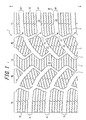
FIG. 1 is a partial plan view of an exemplary tread of a pneumatic tire according to the disclosure; -
FIG. 2 is a partial enlarged view of the plan view ofFIG. 1 ; and -
FIG. 3 is a half sectional view, in the tire width direction, of the pneumatic tire illustrated inFIG. 1 , taken along the line III-III. - Hereinafter, the pneumatic tire of the disclosure will be described in detail with reference to the drawings.
- As shown in
FIG. 1 , a pneumatic tire 1 according to an example of the disclosure herein includes, on a tread surface, a pair ofcircumferential grooves 2 extending on both sides of the tire equator C, a plurality of lateral grooves 3 each continuously extending in a tire width direction between a tread edge TE and a rib-shaped center land row CL defined by the pair ofcircumferential grooves 2, and longitudinal grooves 4 disposed on the outsides of thecircumferential grooves 2 in the tire width direction and each communicating between the lateral grooves 3 that are adjacent to each other in a tire circumference direction. - On each outside, in the tire width direction, of the center land row CL, a middle block row ML is provided that consists of a plurality of middle blocks each defined by the
circumferential groove 2, the longitudinal groove 4, and the lateral grooves 3. Further, on the outside, in the tire width direction, of each middle block row ML, an edge block row EL is provided that consists of a plurality of edge blocks each defined by the longitudinal groove 4, the tread edge TE, and the lateral grooves 3. - Each of the center land row CL, the middle block row ML, and the edge block row EL includes a plurality of sipes S. The sipes S may take any shape. For example, the sipes S may be so-what is called three-dimensional sipes or two-dimensional sipes. Also, the sipes S may extend in any direction. For example, as shown in
FIG. 1 , a plurality of sipes S oriented in the tire with direction may be provided in the center land row CL, the middle block row ML, and the edge block row EL so as to increase an edge component in the tire width direction. Alternatively, a plurality of sipes S oriented in the tire circumference direction may be provided to increase an edge component in the tire circumference direction. By providing the sipes S as such, a scratch effect in a desired direction can be increased on a snow-covered road, so that on-snow performance can be improved. - The pneumatic tire 1 is a tire with a rotation direction that is specified by known means. In use, the pneumatic tire 1 is fitted to a vehicle to rotate downwardly in
FIG. 1 when rotated in a normal direction (i.e., when moving forward). - The pair of
circumferential grooves 2 extending in the tire circumference direction are bent with amplitude in the tire width direction. Specifically, as shown inFIG. 1 , thecircumferential grooves 2 have a zigzag shape, or specifically have bends each of which is convex toward the inside in the tire width direction between two lateral grooves 3 that are adjacent to each other in the tire circumference direction. - As shown in
FIG. 1 , each lateral groove 3 extends at an angle relative to the tire width direction. More specifically, the lateral groove 3 extending at an angle is bent twice toward an other tire circumferential side B. Thelateral grooves FIG. 1 ) and thelateral grooves FIG. 1 ) are both arranged in parallel in the tire circumference direction at a constant pitch. The positions where thelateral grooves lateral grooves - Each lateral groove 3 includes a lateral groove
first portion 31, a lateral groovesecond portion 32 disposed further outward, in the tire width direction, than the lateral groovefirst portion 31, and a lateralgroove step portion 33 that connects the lateral groovefirst portion 31 and the lateral groovesecond portion 32. - The lateral groove
first portion 31 extends to form a curve that is convex toward the other tire circumferential side B. The lateral groovefirst portion 31 has projections and recesses on one tire circumferential side A and on the other tire circumferential side B as seen in a planar view. More specifically, inFIG. 1 , the portion of the groove wall of the lateral groovefirst portion 31 lying on the inner side in the tire width direction and on the one tire circumferential side A and the portion of the groove wall of the lateral groovefirst portion 31 lying on the outer side in the tire width direction and on the other tire circumferential side B extend with projections and recesses, as seen in a planar view. - Similarly to the lateral groove
first portion 31, the lateral groovesecond portion 32 extends to form a curve that is convex toward the other tire circumferential side B. The lateral groovesecond portion 32 has a part that extends zigzag as seen in a planar view. More specifically, the portion of the groove wall of the lateral groovesecond portion 32 lying on the outer side in the tire width direction extends with projections and recesses as seen in a planar view. The inclination angles of the lateral groovefirst portion 31 and the lateral groovesecond portion 32 relative to the tire width direction decreases gradually toward the tread edge. - In this regard, as shown in
FIG. 2 , the lateral groovefirst portion 31 has a groove width center line l1, and a groove width center X at the outer end, in the tire width direction, of the lateral groovefirst portion 31. Further, the lateral groovesecond portion 32 has a groove width center line l2, and a groove width center Y at the inner end, in the tire width direction, of the lateral groovesecond portion 32. The groove width center X at the outer end, in the tire width direction, of the lateral groovefirst portion 31 is disposed closer to the one tire circumferential side A than the groove width center Y at the inner end, in the tire width direction, of the lateral groovesecond portion 32. More specifically, inFIG. 2 , the groove width center X is disposed closer to the one tire circumferential side A and further inward, in the tire width direction, than the groove width center Y at the inner end, in the tire width direction, of the lateral groovesecond portion 32. - The lateral
groove step portion 33 extends straight at an angle relative to the tire circumference direction so as to connect the outer end, in the tire width direction, of the lateral groovefirst portion 31 and the inner end, in the tire width direction, of the lateral groovesecond portion 32. More specifically, inFIGS. 1 and2 , the lateralgroove step portion 33 extends at an angle relative to the tire circumference direction line toward the outside in the tire width direction. For example, the lateralgroove step portion 33 extends at an angle of 20 to 70° relative to the tire circumference direction line toward the outside in the tire width direction. - The dimension of the lateral
groove step portion 33 along the tire width direction is 20% or less the dimension of the lateral groove 3 along the tire width direction. For example, the dimension of the lateralgroove step portion 33 along the tire width direction is 5 to 12 mm. - The longitudinal grooves 4 are bent twice and extend at an angle relative the tire circumference direction toward the side opposite the side the lateral
groove step portion 33 extends. More specifically, inFIGS. 1 and2 , the longitudinal grooves 4 extend at an angle relative to the tire circumference direction line toward the inside in the tire width direction. For example, the longitudinal grooves 4 extend at an angle of 5 to 40° relative the tire circumference direction line toward the inside in the tire width direction. - The end portion of one of the longitudinal groove 4 on the one tire circumferential side A joins an area where the lateral groove
second portion 32 and the lateralgroove step portion 33 of thelateral groove 3R on the one tire circumferential side A join together. The end portion of the longitudinal groove 4 on the other tire circumferential side B joins an area where the lateral groove first portion 31' and the lateral groove step portion 33' of thelateral groove 3R' on the other tire circumferential side B join together. - As shown in
FIGS. 1 and2 , the areas circumferentially adjacent to each other where the lateral groovefirst portions 31 and the longitudinal grooves 4 join together are disposed on an identical tire circumference direction line. Further, the areas circumferentially adjacent to each other where the lateral groovesecond portions 32 and the longitudinal grooves 4 join together are disposed on an identical tire circumference direction line. - Still further, as shown in
FIG. 3 , the depth of the longitudinal grooves 4 is shallower than the depth of thecircumferential grooves 2. Although not shown, the depth of the longitudinal grooves 4 may be shallower than the depth of the lateral grooves 3. - Each of the longitudinal grooves 4 includes a longitudinal groove
first portion 41 disposed on the other tire circumferential side B, a longitudinal groovesecond portion 42 disposed on the one tire circumferential side A, and a longitudinalgroove step portion 43 that connects the longitudinal groovefirst portion 41 and the longitudinal groovesecond portion 42. The inclination angle of the longitudinalgroove step portion 43 relative to the tire circumference direction is greater than the inclination angles of the longitudinal groovefirst portion 41 and the longitudinal groovesecond portion 42 relative to the tire circumference direction. For example, the longitudinalgroove step portion 43 is inclined, relative to the tire circumference direction line, toward the inside in the tire width direction at an angle of 50 to 90°. - The dimension of the longitudinal
groove step portion 43 along the tire circumference direction is 40% or less the dimension of the longitudinal groove 4 along the tire circumference direction. For example, the dimension of the longitudinalgroove step portion 43 along the tire circumference direction is 3 to 7 mm. - As described above, the pneumatic tire 1 includes the rib-shaped center land row CL at the center region of the tire tread surface. Such a pneumatic tire 1 with the rib-shaped center land row CL demonstrates superior steering stability performance particularly on dry road surface.
- The center land row CL is provided with sipes S, which ensures that the edge component is sufficiently provided without lowering rigidity of the land, as compared with case where the center land row CL is provided with grooves.
- The lateral groove
first portion 31 and the lateral groovesecond portion 32 of each lateral groove 3 extend to form a curve that is convex toward the other tire circumferential side B, and the inclination angles of the lateral groovefirst portion 31 and the lateral groovesecond portion 32 relative to the tire width direction decrease toward the tread edge TE. These features allow the pneumatic tire 1 to successfully form snow columns within the lateral grooves on the tread edge sides where the inclination angle of the lateral grooves 3 is small. Thus, the pneumatic tire 1 can further improve on-snow performance. - While the lateral grooves 3 are arranged at a constant pitch, the position where the
lateral groove 3L, disposed on one side of the tire equator C in the tire width direction, is arranged is circumferentially off-set from the position where thelateral groove 3R, disposed on the other side in the tire width direction, is arranged. Thus, the pneumatic tire 1 can reduce the pattern noise of tire rolling, as compared with a case where thelateral grooves - Furthermore, in the exemplary pneumatic tire 1, the pair of
circumferential grooves 2 are bent with amplitude in the tire width direction. This ensures that the edge component are sufficiently provided in both the tire width and the tire circumference directions, as compared with a case where circumferential grooves are extending straight, so that steering stability can be eusured. Furthermore, the exemplary pneumatic tire 1 allows successful formation of snow columns within thecircumferential grooves 2, and improves snow column shear force to further improve on-snow performance. - The lateral grooves 3 include the lateral
groove step portions 33 extending at an angle relative to the tire circumference direction. This increases the edge component with respect to the tire circumference direction and thus turning performance on snow-covered road can be improved. - In particular, the lateral
groove step portion 33, which connects the lateral groovefirst portion 31 and the lateral groovesecond portion 32, can increase an edge portion of the blocks constituting the middle land row ML on the outer side, in the tire width direction, of the one tire circumferential side A. This allows the edges to scratch the road surface on the outer side in the tire width direction where ground contact area increases in turning, so that turning performance can be improved. - Further, the lateral groove
first portion 31 has the projections and recesses on the one tire circumferential side A and on the other tire circumferential side B as seen in a planar view. This increases the edge component in the blocks constituting the middle land row ML and allows such edges to provide road surface-scratching effect. This also allows successful formation of snow columns within the lateral grooves 3, improving snow column shear force to further improve on-snow performance. - The lateral groove
second portion 32 has the zigzag shape as seen in a planar view. This allows the edge component to be sufficiently provided to the shoulder portions, where high pressure is applied in braking. The braking performance can be thus improved. - In the pneumatic tire 1, the lateral grooves 3 each include a lateral
groove step portion 33; the longitudinal grooves 4 each extend at an angle relative to the tire circumference direction toward the side opposite the side the lateralgroove step portion 33 extends; the end portion of the longitudinal groove 4 on the one tire circumferential side A joins the area where the lateral groovesecond portion 32 and the lateralgroove step portion 33 of the lateral groove 3 on the one tire circumferential side A join together; and the end portion of the longitudinal groove 4 on the other tire circumferential side B join the area where the lateral groove first portion 31' and the lateral groove step portion 33' of the lateral groove 3' on the other tire circumferential side B join together. These features allow the pneumatic tire 1 to demonstrate superior drainage performance while maintaining on-snow performance. - Specifically, in wet road surface running, water having entered the
circumferential groove 2 from the one tire circumferential side A flows through the lateral groovefirst portion 31 and, at the area where the lateral groovefirst portion 31 and the lateralgroove step portion 33 join together, meets water flowing through thelongitudinal groove 4a to enter the lateralgroove step portion 33. The water having entered the lateralgroove step portion 33 is then split, at the area where the lateralgroove step portion 33 and the lateral groovesecond portion 32 join together, into thelongitudinal groove 4b and the lateral groovesecond portion 32. The water having entered the lateral groovesecond portion 32 flows to the tread edge of the tire to be drained. On the other hand, the water having entered thelongitudinal groove 4b meets, at the area where the lateral groove first portion 31' and the lateral groove step portion 33' of thelateral groove 3R' on the other tire circumferential side B join together, the water having flown through thecircumferential groove 2 and then the lateral groove first portion 31' to enter the lateral groove step portion 33'. The water having entered the lateral groove step portion 33' is split, at the area where the lateral groove step portion 33' and the lateral groove second portion 32' join together, into thelongitudinal groove 4c and the lateral groove second portion 32'. The water having entered the lateral groove second portion 32' flows to the tread edge TE of the tire to be drained, and the water having entered thelongitudinal groove 4c further enters thelateral groove 3R". With such water flow through the grooves, the pneumatic tire 1, which has meeting points of the longitudinal grooves 4 and the lateral grooves 3, nonetheless can keep a constant inflow and outflow at the meeting points. This allows the pneumatic tire 1 to efficiently drain water, without impairing on-snow performance, allowing the pneumatic tire 1 to demonstrate superior drainage performance. In addition to making the pattern of the lateralgroove step portion 33 and the longitudinal groove 4 as such, the depth of the longitudinal grooves 4 can be made shallower than the depth of thecircumferential grooves 2. This would further enhance the water flow through the lateral grooves in wet road surface running, further improving drainage performance. - In the pneumatic tire 1, the longitudinal groove 4 includes the longitudinal
groove step portion 43 that has a greater inclination angle, relative to the tire circumference direction, than the longitudinal groovefirst portion 41 and the longitudinal groovesecond portion 42. With this, the edge component in the tire width direction is increased so that driving performance can be improved. - With the longitudinal grooves 4 having a depth shallower than the
circumferential grooves 2, rigidity of the blocks disposed on the outer side in the tire width direction, or specifically rigidity of the blocks constituting the middle land rows ML and the edge land rows EL, can be ensured. Thus, inclination of the blocks disposed on the outer side in the tire width direction can be prevented so that the ground contact area can be sufficiently provided, and thus braking performance as well as turning performance can be improved. If the depth of the longitudinal grooves 4 is made shallower than the depth of the lateral grooves 3, water flow through the lateral grooves 3 may further be enhanced in wet road surface running, and thus drainage performance can be improved. - With the longitudinal grooves 4 that extend at an angle relative to the tire circumference direction line toward the side opposite the side the lateral
groove step portion 33 extends (i.e., toward the inner side in the tire width direction), the angle of the edges at the end portions, on the one tire circumferential side A, of the blocks constituting the edge land row EL is increased, as compared with a case where the longitudinal grooves 4 extend at an angle relative to the tire circumference direction line toward the same side as the lateralgroove step portion 33 extends (i.e., toward the outer side in the tire width direction). This ensures that the blocks constituting the edge land row EL have sufficient rigidity. Furthermore, with the lateralgroove step portion 33, acute-angled portions can be eliminated from the middle land row ML at the outer side in the tire width direction and on the one tire circumferential side A, and from the edge land row EL at the inner side in the tire width direction and on the other tire circumferential side B. This ensures that the blocks have sufficient rigidity. - In the foregoing, an example of the pneumatic tire according to the disclosure has been described with reference to the drawings. However, the pneumatic tire of the disclosure is not limited to the above example; the pneumatic tire of the disclosure can be modified as appropriate.
-
- 1
- Pneumatic tire
- 2
- Circumferential groove
- 3R, 3R', 3R", 3L, 3L', 3L"
- Lateral groove
- 4a, 4b, 4c, 4d
- Longitudinal groove
- 31, 31'
- Lateral groove first portion
- 32, 32'
- Lateral groove second portion
- 33, 33'
- Lateral groove step portion
- 41
- Longitudinal groove first portion
- 42
- Longitudinal groove second portion
- 43
- Longitudinal groove step portion
- l1, l1'
- Groove center line of the lateral groove first portion
- l2, l2'
- Groove center line of the lateral groove second portion
- X, X'
- Groove width center of the outer end, in the tire width direction, of the lateral groove first portion
- Y, Y'
- Groove width center of the inner end, in the tire width direction, of the lateral groove second portion
- A
- One tire circumferential side
- B
- The other tire circumferential side
- C
- Tire equator
- CL
- Center land row
- ML
- Middle land row
- EL
- Edge land row
- S
- Sipe
- TE
- Tread edge
Claims (4)
- A pneumatic tire comprising, on a tread surface:a pair of circumferential grooves extending on both sides of a tire equator;a plurality of lateral grooves each extending in a tire width direction between a rib-shaped center land row and a tread edge, the rib-shaped center land row being defined by the pair of circumferential grooves; andlongitudinal grooves disposed on the outsides, in the tire width direction, of the circumferential grooves, each of the longitudinal grooves communicating between the lateral grooves that are adjacent to each other in a tire circumference direction, whereineach of the lateral grooves includes a lateral groove first portion, a lateral groove second portion disposed further outward, in the tire width direction, than the lateral groove first portion, and a lateral groove step portion connecting the lateral groove first portion and the lateral groove second portion,a groove width center of the outer end, in the tire width direction, of the lateral groove first portion is disposed closer to one tire circumferential side than a groove width center of the inner end, in the tire width direction, of the lateral groove second portion,the lateral groove step portion extends at an angle relative to the tire circumference direction so as to connect the outer end, in the tire width direction, of the lateral groove first portion and the inner end, in the tire width direction, of the lateral groove second portion,the longitudinal grooves extend at an angle relative to the tire circumference direction toward the side opposite the side the lateral groove step portion extends,the end portion on the one tire circumferential side of each of the longitudinal grooves joins an area where the lateral groove second portion and the lateral groove step portion of the lateral groove on the one tire circumferential side join together, andthe end portion on the other tire circumferential side of each of the longitudinal grooves joins an area where the lateral groove first portion and the lateral groove step portion of the lateral groove on the other tire circumferential side join together.
- The pneumatic tire according to claim 1, wherein
each of the longitudinal grooves includes a longitudinal groove first portion, a longitudinal groove second portion disposed on the one tire circumferential side of the longitudinal groove first portion, and a longitudinal groove step portion connecting the longitudinal groove first portion and the longitudinal groove second portion, and
an inclination angle of the longitudinal groove step portion relative to the tire circumference direction is greater than inclination angles of the longitudinal groove first portion and the longitudinal groove second portion relative to the tire circumference direction. - The pneumatic tire according to claim 1 or 2, wherein the depth of the longitudinal grooves is shallower than the depth of the circumferential grooves.
- The pneumatic tire according to any one of claims 1 to 3, wherein the lateral groove second portion has a part extending zigzag as seen in a planar view.
Applications Claiming Priority (2)
| Application Number | Priority Date | Filing Date | Title |
|---|---|---|---|
| JP2013023578A JP5620529B2 (en) | 2013-02-08 | 2013-02-08 | Pneumatic tire |
| PCT/JP2014/000639 WO2014122932A1 (en) | 2013-02-08 | 2014-02-06 | Pneumatic tire |
Publications (3)
| Publication Number | Publication Date |
|---|---|
| EP2955036A1 true EP2955036A1 (en) | 2015-12-16 |
| EP2955036A4 EP2955036A4 (en) | 2016-10-26 |
| EP2955036B1 EP2955036B1 (en) | 2018-12-12 |
Family
ID=51299531
Family Applications (1)
| Application Number | Title | Priority Date | Filing Date |
|---|---|---|---|
| EP14748799.5A Not-in-force EP2955036B1 (en) | 2013-02-08 | 2014-02-06 | Pneumatic tire |
Country Status (6)
| Country | Link |
|---|---|
| US (1) | US10245893B2 (en) |
| EP (1) | EP2955036B1 (en) |
| JP (1) | JP5620529B2 (en) |
| CN (1) | CN105008147B (en) |
| RU (1) | RU2607491C1 (en) |
| WO (1) | WO2014122932A1 (en) |
Families Citing this family (9)
| Publication number | Priority date | Publication date | Assignee | Title |
|---|---|---|---|---|
| JP6367139B2 (en) * | 2015-02-27 | 2018-08-01 | 東洋ゴム工業株式会社 | Pneumatic tire |
| USD782960S1 (en) * | 2015-10-02 | 2017-04-04 | Nokian Tyres Plc | Tyre |
| JP6744085B2 (en) * | 2015-11-17 | 2020-08-19 | Toyo Tire株式会社 | Pneumatic tire |
| JP6711172B2 (en) * | 2016-06-27 | 2020-06-17 | 住友ゴム工業株式会社 | tire |
| EP3323637B1 (en) * | 2016-11-22 | 2019-09-04 | Sumitomo Rubber Industries, Ltd. | Tire |
| CN108725101B (en) * | 2017-04-18 | 2021-12-03 | 住友橡胶工业株式会社 | Tyre for vehicle wheels |
| CN108859613B (en) * | 2017-05-16 | 2021-09-24 | 住友橡胶工业株式会社 | Tyre for vehicle wheels |
| WO2018235345A1 (en) * | 2017-06-22 | 2018-12-27 | 株式会社ブリヂストン | Heavy-load tire |
| JP7178813B2 (en) | 2018-07-04 | 2022-11-28 | 株式会社ブリヂストン | tire |
Family Cites Families (16)
| Publication number | Priority date | Publication date | Assignee | Title |
|---|---|---|---|---|
| JPS55114605A (en) | 1979-02-28 | 1980-09-04 | Yokohama Rubber Co Ltd:The | All-weather tire |
| JPH01297302A (en) * | 1988-05-24 | 1989-11-30 | Bridgestone Corp | Pneumatic tyre |
| JPH09226324A (en) * | 1996-02-29 | 1997-09-02 | Bridgestone Corp | Pneumatic tire |
| JPH1024707A (en) * | 1996-07-08 | 1998-01-27 | Yokohama Rubber Co Ltd:The | Pneumatic tire for ice/snow road |
| JP3378789B2 (en) * | 1998-02-27 | 2003-02-17 | 住友ゴム工業株式会社 | Pneumatic tire |
| DE19829038C2 (en) * | 1998-07-01 | 2002-07-25 | Continental Ag | vehicle tires |
| JP4233665B2 (en) * | 1999-02-10 | 2009-03-04 | 株式会社ブリヂストン | Pneumatic tire |
| JP2002036820A (en) * | 2000-07-24 | 2002-02-06 | Bridgestone Corp | Pneumatic tire |
| DE10301012A1 (en) * | 2003-01-13 | 2004-07-22 | Continental Aktiengesellschaft | Pneumatic vehicle tires in particular for use in winter driving conditions |
| JP3943506B2 (en) | 2003-01-24 | 2007-07-11 | 住友ゴム工業株式会社 | Pneumatic tire |
| JP5045383B2 (en) * | 2007-11-15 | 2012-10-10 | 横浜ゴム株式会社 | Pneumatic tire |
| CN101722794B (en) * | 2008-10-16 | 2011-12-21 | 横滨橡胶株式会社 | Pneumatic tire |
| JP4656239B2 (en) | 2009-01-23 | 2011-03-23 | 横浜ゴム株式会社 | Pneumatic tire |
| JP5149957B2 (en) * | 2010-12-14 | 2013-02-20 | 住友ゴム工業株式会社 | Pneumatic tire |
| JP5665611B2 (en) * | 2011-03-07 | 2015-02-04 | 株式会社ブリヂストン | Pneumatic tire |
| JP5083451B1 (en) * | 2011-12-07 | 2012-11-28 | 横浜ゴム株式会社 | Pneumatic tire |
-
2013
- 2013-02-08 JP JP2013023578A patent/JP5620529B2/en active Active
-
2014
- 2014-02-06 US US14/762,907 patent/US10245893B2/en not_active Expired - Fee Related
- 2014-02-06 CN CN201480008078.6A patent/CN105008147B/en not_active Expired - Fee Related
- 2014-02-06 RU RU2015138150A patent/RU2607491C1/en active
- 2014-02-06 EP EP14748799.5A patent/EP2955036B1/en not_active Not-in-force
- 2014-02-06 WO PCT/JP2014/000639 patent/WO2014122932A1/en active Application Filing
Also Published As
| Publication number | Publication date |
|---|---|
| JP5620529B2 (en) | 2014-11-05 |
| EP2955036B1 (en) | 2018-12-12 |
| US10245893B2 (en) | 2019-04-02 |
| CN105008147B (en) | 2017-06-06 |
| JP2014151786A (en) | 2014-08-25 |
| US20150352902A1 (en) | 2015-12-10 |
| RU2607491C1 (en) | 2017-01-10 |
| EP2955036A4 (en) | 2016-10-26 |
| CN105008147A (en) | 2015-10-28 |
| WO2014122932A1 (en) | 2014-08-14 |
Similar Documents
| Publication | Publication Date | Title |
|---|---|---|
| EP2955036B1 (en) | Pneumatic tire | |
| RU2632243C2 (en) | Pneumatic motor tire | |
| EP3086957B1 (en) | Tyre for vehicle wheels having improved tread pattern | |
| CN107160948B (en) | Tire tread pattern structure for motor two-wheeled vehicle | |
| US20170246914A1 (en) | Tire Traction Element | |
| JP5679105B2 (en) | Pneumatic tire and its vulcanization mold | |
| US10350946B2 (en) | Snow tire with directional paddles | |
| JP6434270B2 (en) | Pneumatic tire for snow | |
| JP5480866B2 (en) | Pneumatic tire | |
| US20140116589A1 (en) | Pneumatic Tire | |
| EP2821258A1 (en) | Pneumatic tire | |
| JP6046471B2 (en) | Pneumatic tire | |
| RU2016125287A (en) | Winter tire | |
| JP4570262B2 (en) | Pneumatic tire | |
| JP6867121B2 (en) | Pneumatic tires | |
| CN107709046A (en) | Pneumatic tire | |
| US10266014B2 (en) | Tire having circumferentially biased sipe depths | |
| JPH06305307A (en) | Pneumatic tire used in winter time | |
| JP6579895B2 (en) | Pneumatic tire | |
| JP2011140248A (en) | Pneumatic tire | |
| JP5353975B2 (en) | Pneumatic tire | |
| JP2017071280A (en) | Pneumatic tire | |
| JP2006273328A (en) | Pneumatic tire | |
| JP5805244B2 (en) | Pneumatic tire |
Legal Events
| Date | Code | Title | Description |
|---|---|---|---|
| PUAI | Public reference made under article 153(3) epc to a published international application that has entered the european phase |
Free format text: ORIGINAL CODE: 0009012 |
|
| 17P | Request for examination filed |
Effective date: 20150727 |
|
| AK | Designated contracting states |
Kind code of ref document: A1 Designated state(s): AL AT BE BG CH CY CZ DE DK EE ES FI FR GB GR HR HU IE IS IT LI LT LU LV MC MK MT NL NO PL PT RO RS SE SI SK SM TR |
|
| AX | Request for extension of the european patent |
Extension state: BA ME |
|
| DAX | Request for extension of the european patent (deleted) | ||
| A4 | Supplementary search report drawn up and despatched |
Effective date: 20160922 |
|
| RIC1 | Information provided on ipc code assigned before grant |
Ipc: B60C 11/04 20060101AFI20160916BHEP |
|
| STAA | Information on the status of an ep patent application or granted ep patent |
Free format text: STATUS: EXAMINATION IS IN PROGRESS |
|
| 17Q | First examination report despatched |
Effective date: 20171128 |
|
| REG | Reference to a national code |
Ref country code: DE Ref legal event code: R079 Ref document number: 602014037839 Country of ref document: DE Free format text: PREVIOUS MAIN CLASS: B60C0011040000 Ipc: B60C0011120000 |
|
| GRAP | Despatch of communication of intention to grant a patent |
Free format text: ORIGINAL CODE: EPIDOSNIGR1 |
|
| STAA | Information on the status of an ep patent application or granted ep patent |
Free format text: STATUS: GRANT OF PATENT IS INTENDED |
|
| RIC1 | Information provided on ipc code assigned before grant |
Ipc: B60C 11/03 20060101ALI20180523BHEP Ipc: B60C 11/12 20060101AFI20180523BHEP |
|
| INTG | Intention to grant announced |
Effective date: 20180627 |
|
| GRAS | Grant fee paid |
Free format text: ORIGINAL CODE: EPIDOSNIGR3 |
|
| GRAA | (expected) grant |
Free format text: ORIGINAL CODE: 0009210 |
|
| STAA | Information on the status of an ep patent application or granted ep patent |
Free format text: STATUS: THE PATENT HAS BEEN GRANTED |
|
| AK | Designated contracting states |
Kind code of ref document: B1 Designated state(s): AL AT BE BG CH CY CZ DE DK EE ES FI FR GB GR HR HU IE IS IT LI LT LU LV MC MK MT NL NO PL PT RO RS SE SI SK SM TR |
|
| REG | Reference to a national code |
Ref country code: GB Ref legal event code: FG4D |
|
| REG | Reference to a national code |
Ref country code: CH Ref legal event code: EP |
|
| REG | Reference to a national code |
Ref country code: AT Ref legal event code: REF Ref document number: 1075446 Country of ref document: AT Kind code of ref document: T Effective date: 20181215 |
|
| REG | Reference to a national code |
Ref country code: IE Ref legal event code: FG4D |
|
| REG | Reference to a national code |
Ref country code: DE Ref legal event code: R096 Ref document number: 602014037839 Country of ref document: DE |
|
| REG | Reference to a national code |
Ref country code: NL Ref legal event code: MP Effective date: 20181212 |
|
| REG | Reference to a national code |
Ref country code: LT Ref legal event code: MG4D |
|
| PG25 | Lapsed in a contracting state [announced via postgrant information from national office to epo] |
Ref country code: HR Free format text: LAPSE BECAUSE OF FAILURE TO SUBMIT A TRANSLATION OF THE DESCRIPTION OR TO PAY THE FEE WITHIN THE PRESCRIBED TIME-LIMIT Effective date: 20181212 Ref country code: LT Free format text: LAPSE BECAUSE OF FAILURE TO SUBMIT A TRANSLATION OF THE DESCRIPTION OR TO PAY THE FEE WITHIN THE PRESCRIBED TIME-LIMIT Effective date: 20181212 Ref country code: ES Free format text: LAPSE BECAUSE OF FAILURE TO SUBMIT A TRANSLATION OF THE DESCRIPTION OR TO PAY THE FEE WITHIN THE PRESCRIBED TIME-LIMIT Effective date: 20181212 Ref country code: NO Free format text: LAPSE BECAUSE OF FAILURE TO SUBMIT A TRANSLATION OF THE DESCRIPTION OR TO PAY THE FEE WITHIN THE PRESCRIBED TIME-LIMIT Effective date: 20190312 Ref country code: FI Free format text: LAPSE BECAUSE OF FAILURE TO SUBMIT A TRANSLATION OF THE DESCRIPTION OR TO PAY THE FEE WITHIN THE PRESCRIBED TIME-LIMIT Effective date: 20181212 Ref country code: BG Free format text: LAPSE BECAUSE OF FAILURE TO SUBMIT A TRANSLATION OF THE DESCRIPTION OR TO PAY THE FEE WITHIN THE PRESCRIBED TIME-LIMIT Effective date: 20190312 Ref country code: LV Free format text: LAPSE BECAUSE OF FAILURE TO SUBMIT A TRANSLATION OF THE DESCRIPTION OR TO PAY THE FEE WITHIN THE PRESCRIBED TIME-LIMIT Effective date: 20181212 |
|
| REG | Reference to a national code |
Ref country code: AT Ref legal event code: MK05 Ref document number: 1075446 Country of ref document: AT Kind code of ref document: T Effective date: 20181212 |
|
| PG25 | Lapsed in a contracting state [announced via postgrant information from national office to epo] |
Ref country code: RS Free format text: LAPSE BECAUSE OF FAILURE TO SUBMIT A TRANSLATION OF THE DESCRIPTION OR TO PAY THE FEE WITHIN THE PRESCRIBED TIME-LIMIT Effective date: 20181212 Ref country code: SE Free format text: LAPSE BECAUSE OF FAILURE TO SUBMIT A TRANSLATION OF THE DESCRIPTION OR TO PAY THE FEE WITHIN THE PRESCRIBED TIME-LIMIT Effective date: 20181212 Ref country code: AL Free format text: LAPSE BECAUSE OF FAILURE TO SUBMIT A TRANSLATION OF THE DESCRIPTION OR TO PAY THE FEE WITHIN THE PRESCRIBED TIME-LIMIT Effective date: 20181212 Ref country code: GR Free format text: LAPSE BECAUSE OF FAILURE TO SUBMIT A TRANSLATION OF THE DESCRIPTION OR TO PAY THE FEE WITHIN THE PRESCRIBED TIME-LIMIT Effective date: 20190313 |
|
| PG25 | Lapsed in a contracting state [announced via postgrant information from national office to epo] |
Ref country code: NL Free format text: LAPSE BECAUSE OF FAILURE TO SUBMIT A TRANSLATION OF THE DESCRIPTION OR TO PAY THE FEE WITHIN THE PRESCRIBED TIME-LIMIT Effective date: 20181212 |
|
| PG25 | Lapsed in a contracting state [announced via postgrant information from national office to epo] |
Ref country code: PL Free format text: LAPSE BECAUSE OF FAILURE TO SUBMIT A TRANSLATION OF THE DESCRIPTION OR TO PAY THE FEE WITHIN THE PRESCRIBED TIME-LIMIT Effective date: 20181212 Ref country code: CZ Free format text: LAPSE BECAUSE OF FAILURE TO SUBMIT A TRANSLATION OF THE DESCRIPTION OR TO PAY THE FEE WITHIN THE PRESCRIBED TIME-LIMIT Effective date: 20181212 Ref country code: PT Free format text: LAPSE BECAUSE OF FAILURE TO SUBMIT A TRANSLATION OF THE DESCRIPTION OR TO PAY THE FEE WITHIN THE PRESCRIBED TIME-LIMIT Effective date: 20190412 Ref country code: IT Free format text: LAPSE BECAUSE OF FAILURE TO SUBMIT A TRANSLATION OF THE DESCRIPTION OR TO PAY THE FEE WITHIN THE PRESCRIBED TIME-LIMIT Effective date: 20181212 |
|
| PG25 | Lapsed in a contracting state [announced via postgrant information from national office to epo] |
Ref country code: IS Free format text: LAPSE BECAUSE OF FAILURE TO SUBMIT A TRANSLATION OF THE DESCRIPTION OR TO PAY THE FEE WITHIN THE PRESCRIBED TIME-LIMIT Effective date: 20190412 Ref country code: RO Free format text: LAPSE BECAUSE OF FAILURE TO SUBMIT A TRANSLATION OF THE DESCRIPTION OR TO PAY THE FEE WITHIN THE PRESCRIBED TIME-LIMIT Effective date: 20181212 Ref country code: EE Free format text: LAPSE BECAUSE OF FAILURE TO SUBMIT A TRANSLATION OF THE DESCRIPTION OR TO PAY THE FEE WITHIN THE PRESCRIBED TIME-LIMIT Effective date: 20181212 Ref country code: SM Free format text: LAPSE BECAUSE OF FAILURE TO SUBMIT A TRANSLATION OF THE DESCRIPTION OR TO PAY THE FEE WITHIN THE PRESCRIBED TIME-LIMIT Effective date: 20181212 Ref country code: SK Free format text: LAPSE BECAUSE OF FAILURE TO SUBMIT A TRANSLATION OF THE DESCRIPTION OR TO PAY THE FEE WITHIN THE PRESCRIBED TIME-LIMIT Effective date: 20181212 |
|
| REG | Reference to a national code |
Ref country code: DE Ref legal event code: R097 Ref document number: 602014037839 Country of ref document: DE |
|
| REG | Reference to a national code |
Ref country code: CH Ref legal event code: PL |
|
| PLBE | No opposition filed within time limit |
Free format text: ORIGINAL CODE: 0009261 |
|
| STAA | Information on the status of an ep patent application or granted ep patent |
Free format text: STATUS: NO OPPOSITION FILED WITHIN TIME LIMIT |
|
| PG25 | Lapsed in a contracting state [announced via postgrant information from national office to epo] |
Ref country code: MC Free format text: LAPSE BECAUSE OF FAILURE TO SUBMIT A TRANSLATION OF THE DESCRIPTION OR TO PAY THE FEE WITHIN THE PRESCRIBED TIME-LIMIT Effective date: 20181212 Ref country code: AT Free format text: LAPSE BECAUSE OF FAILURE TO SUBMIT A TRANSLATION OF THE DESCRIPTION OR TO PAY THE FEE WITHIN THE PRESCRIBED TIME-LIMIT Effective date: 20181212 Ref country code: DK Free format text: LAPSE BECAUSE OF FAILURE TO SUBMIT A TRANSLATION OF THE DESCRIPTION OR TO PAY THE FEE WITHIN THE PRESCRIBED TIME-LIMIT Effective date: 20181212 Ref country code: LU Free format text: LAPSE BECAUSE OF NON-PAYMENT OF DUE FEES Effective date: 20190206 Ref country code: SI Free format text: LAPSE BECAUSE OF FAILURE TO SUBMIT A TRANSLATION OF THE DESCRIPTION OR TO PAY THE FEE WITHIN THE PRESCRIBED TIME-LIMIT Effective date: 20181212 |
|
| 26N | No opposition filed |
Effective date: 20190913 |
|
| REG | Reference to a national code |
Ref country code: BE Ref legal event code: MM Effective date: 20190228 |
|
| GBPC | Gb: european patent ceased through non-payment of renewal fee |
Effective date: 20190312 |
|
| REG | Reference to a national code |
Ref country code: IE Ref legal event code: MM4A |
|
| PG25 | Lapsed in a contracting state [announced via postgrant information from national office to epo] |
Ref country code: CH Free format text: LAPSE BECAUSE OF NON-PAYMENT OF DUE FEES Effective date: 20190228 Ref country code: LI Free format text: LAPSE BECAUSE OF NON-PAYMENT OF DUE FEES Effective date: 20190228 |
|
| PG25 | Lapsed in a contracting state [announced via postgrant information from national office to epo] |
Ref country code: IE Free format text: LAPSE BECAUSE OF NON-PAYMENT OF DUE FEES Effective date: 20190206 Ref country code: GB Free format text: LAPSE BECAUSE OF NON-PAYMENT OF DUE FEES Effective date: 20190312 |
|
| PG25 | Lapsed in a contracting state [announced via postgrant information from national office to epo] |
Ref country code: BE Free format text: LAPSE BECAUSE OF NON-PAYMENT OF DUE FEES Effective date: 20190228 |
|
| PG25 | Lapsed in a contracting state [announced via postgrant information from national office to epo] |
Ref country code: TR Free format text: LAPSE BECAUSE OF FAILURE TO SUBMIT A TRANSLATION OF THE DESCRIPTION OR TO PAY THE FEE WITHIN THE PRESCRIBED TIME-LIMIT Effective date: 20181212 |
|
| PG25 | Lapsed in a contracting state [announced via postgrant information from national office to epo] |
Ref country code: MT Free format text: LAPSE BECAUSE OF NON-PAYMENT OF DUE FEES Effective date: 20190206 |
|
| PG25 | Lapsed in a contracting state [announced via postgrant information from national office to epo] |
Ref country code: CY Free format text: LAPSE BECAUSE OF FAILURE TO SUBMIT A TRANSLATION OF THE DESCRIPTION OR TO PAY THE FEE WITHIN THE PRESCRIBED TIME-LIMIT Effective date: 20181212 |
|
| PG25 | Lapsed in a contracting state [announced via postgrant information from national office to epo] |
Ref country code: HU Free format text: LAPSE BECAUSE OF FAILURE TO SUBMIT A TRANSLATION OF THE DESCRIPTION OR TO PAY THE FEE WITHIN THE PRESCRIBED TIME-LIMIT; INVALID AB INITIO Effective date: 20140206 |
|
| PGFP | Annual fee paid to national office [announced via postgrant information from national office to epo] |
Ref country code: DE Payment date: 20220217 Year of fee payment: 9 |
|
| PGFP | Annual fee paid to national office [announced via postgrant information from national office to epo] |
Ref country code: FR Payment date: 20220216 Year of fee payment: 9 |
|
| PG25 | Lapsed in a contracting state [announced via postgrant information from national office to epo] |
Ref country code: MK Free format text: LAPSE BECAUSE OF FAILURE TO SUBMIT A TRANSLATION OF THE DESCRIPTION OR TO PAY THE FEE WITHIN THE PRESCRIBED TIME-LIMIT Effective date: 20181212 |
|
| REG | Reference to a national code |
Ref country code: DE Ref legal event code: R119 Ref document number: 602014037839 Country of ref document: DE |
|
| PG25 | Lapsed in a contracting state [announced via postgrant information from national office to epo] |
Ref country code: FR Free format text: LAPSE BECAUSE OF NON-PAYMENT OF DUE FEES Effective date: 20230228 Ref country code: DE Free format text: LAPSE BECAUSE OF NON-PAYMENT OF DUE FEES Effective date: 20230901 |