EP2952807B1 - Pressurized incineration equipment and pressurized incineration method - Google Patents
Pressurized incineration equipment and pressurized incineration method Download PDFInfo
- Publication number
- EP2952807B1 EP2952807B1 EP14746349.1A EP14746349A EP2952807B1 EP 2952807 B1 EP2952807 B1 EP 2952807B1 EP 14746349 A EP14746349 A EP 14746349A EP 2952807 B1 EP2952807 B1 EP 2952807B1
- Authority
- EP
- European Patent Office
- Prior art keywords
- pressurized
- turbocharger
- air
- facility
- turbine impeller
- Prior art date
- Legal status (The legal status is an assumption and is not a legal conclusion. Google has not performed a legal analysis and makes no representation as to the accuracy of the status listed.)
- Active
Links
Images



Classifications
-
- F—MECHANICAL ENGINEERING; LIGHTING; HEATING; WEAPONS; BLASTING
- F01—MACHINES OR ENGINES IN GENERAL; ENGINE PLANTS IN GENERAL; STEAM ENGINES
- F01D—NON-POSITIVE DISPLACEMENT MACHINES OR ENGINES, e.g. STEAM TURBINES
- F01D11/00—Preventing or minimising internal leakage of working-fluid, e.g. between stages
- F01D11/02—Preventing or minimising internal leakage of working-fluid, e.g. between stages by non-contact sealings, e.g. of labyrinth type
- F01D11/04—Preventing or minimising internal leakage of working-fluid, e.g. between stages by non-contact sealings, e.g. of labyrinth type using sealing fluid, e.g. steam
-
- F—MECHANICAL ENGINEERING; LIGHTING; HEATING; WEAPONS; BLASTING
- F23—COMBUSTION APPARATUS; COMBUSTION PROCESSES
- F23C—METHODS OR APPARATUS FOR COMBUSTION USING FLUID FUEL OR SOLID FUEL SUSPENDED IN A CARRIER GAS OR AIR
- F23C10/00—Fluidised bed combustion apparatus
- F23C10/16—Fluidised bed combustion apparatus specially adapted for operation at superatmospheric pressures, e.g. by the arrangement of the combustion chamber and its auxiliary systems inside a pressure vessel
-
- F—MECHANICAL ENGINEERING; LIGHTING; HEATING; WEAPONS; BLASTING
- F23—COMBUSTION APPARATUS; COMBUSTION PROCESSES
- F23C—METHODS OR APPARATUS FOR COMBUSTION USING FLUID FUEL OR SOLID FUEL SUSPENDED IN A CARRIER GAS OR AIR
- F23C10/00—Fluidised bed combustion apparatus
- F23C10/18—Details; Accessories
-
- F—MECHANICAL ENGINEERING; LIGHTING; HEATING; WEAPONS; BLASTING
- F23—COMBUSTION APPARATUS; COMBUSTION PROCESSES
- F23G—CREMATION FURNACES; CONSUMING WASTE PRODUCTS BY COMBUSTION
- F23G5/00—Incineration of waste; Incinerator constructions; Details, accessories or control therefor
- F23G5/30—Incineration of waste; Incinerator constructions; Details, accessories or control therefor having a fluidised bed
-
- F—MECHANICAL ENGINEERING; LIGHTING; HEATING; WEAPONS; BLASTING
- F23—COMBUSTION APPARATUS; COMBUSTION PROCESSES
- F23L—SUPPLYING AIR OR NON-COMBUSTIBLE LIQUIDS OR GASES TO COMBUSTION APPARATUS IN GENERAL ; VALVES OR DAMPERS SPECIALLY ADAPTED FOR CONTROLLING AIR SUPPLY OR DRAUGHT IN COMBUSTION APPARATUS; INDUCING DRAUGHT IN COMBUSTION APPARATUS; TOPS FOR CHIMNEYS OR VENTILATING SHAFTS; TERMINALS FOR FLUES
- F23L5/00—Blast-producing apparatus before the fire
- F23L5/02—Arrangements of fans or blowers
-
- F—MECHANICAL ENGINEERING; LIGHTING; HEATING; WEAPONS; BLASTING
- F05—INDEXING SCHEMES RELATING TO ENGINES OR PUMPS IN VARIOUS SUBCLASSES OF CLASSES F01-F04
- F05D—INDEXING SCHEME FOR ASPECTS RELATING TO NON-POSITIVE-DISPLACEMENT MACHINES OR ENGINES, GAS-TURBINES OR JET-PROPULSION PLANTS
- F05D2220/00—Application
- F05D2220/40—Application in turbochargers
-
- F—MECHANICAL ENGINEERING; LIGHTING; HEATING; WEAPONS; BLASTING
- F23—COMBUSTION APPARATUS; COMBUSTION PROCESSES
- F23G—CREMATION FURNACES; CONSUMING WASTE PRODUCTS BY COMBUSTION
- F23G2200/00—Waste incineration
-
- F—MECHANICAL ENGINEERING; LIGHTING; HEATING; WEAPONS; BLASTING
- F23—COMBUSTION APPARATUS; COMBUSTION PROCESSES
- F23G—CREMATION FURNACES; CONSUMING WASTE PRODUCTS BY COMBUSTION
- F23G2202/00—Combustion
- F23G2202/30—Combustion in a pressurised chamber
-
- F—MECHANICAL ENGINEERING; LIGHTING; HEATING; WEAPONS; BLASTING
- F23—COMBUSTION APPARATUS; COMBUSTION PROCESSES
- F23G—CREMATION FURNACES; CONSUMING WASTE PRODUCTS BY COMBUSTION
- F23G2203/00—Furnace arrangements
- F23G2203/50—Fluidised bed furnace
- F23G2203/502—Fluidised bed furnace with recirculation of bed material inside combustion chamber
-
- F—MECHANICAL ENGINEERING; LIGHTING; HEATING; WEAPONS; BLASTING
- F23—COMBUSTION APPARATUS; COMBUSTION PROCESSES
- F23L—SUPPLYING AIR OR NON-COMBUSTIBLE LIQUIDS OR GASES TO COMBUSTION APPARATUS IN GENERAL ; VALVES OR DAMPERS SPECIALLY ADAPTED FOR CONTROLLING AIR SUPPLY OR DRAUGHT IN COMBUSTION APPARATUS; INDUCING DRAUGHT IN COMBUSTION APPARATUS; TOPS FOR CHIMNEYS OR VENTILATING SHAFTS; TERMINALS FOR FLUES
- F23L2900/00—Special arrangements for supplying or treating air or oxidant for combustion; Injecting inert gas, water or steam into the combustion chamber
- F23L2900/05021—Gas turbine driven blowers for supplying combustion air or oxidant, i.e. turbochargers
Definitions
- the present invention relates to a pressurized incineration facility and a pressurized incineration method.
- Patent Document 1 shown below discloses a pressurized incinerator facility and a start-up method thereof, in which a blower used to start up a turbocharger is provided on the upstream side of an air inlet pipe of the turbocharger in order to reduce the production cost or the running cost thereof.
- the pressurized incinerator facility includes the turbocharger which produces compressed air by using high-temperature exhaust gas exhausted from a pressurized-fluidized bed incinerator and which supplies the compressed air to the pressurized-fluidized bed incinerator.
- the pressurized incinerator facility supplies start-up air from the blower to a compressor of the turbocharger at the time of start-up of the facility.
- Patent Document 2 discloses a technology to prevent leakage (leakage into the bearing) of exhaust gas imported to a turbine, the leakage being prevented by a gasket which blocks and seals a gap by using gas pressure.
- a turbine shaft (rotary shaft) of a turbine impeller is supported by a bearing mechanism, and the bearing mechanism obtains the bearing performance thereof by lubricating oil.
- a gas bearing device being an example of the bearing mechanism, in which the rotary shaft is inserted into a journal bearing with a gap formed therebetween and is supported in a state of being floated by pressurized air supplied from outside of the device, is costly because the device is complicated, and has no actual example of adoption for mass production.
- high-temperature exhaust gas exhausted from the pressurized-fluidized bed incinerator flows into the turbocharger so as to serve as a drive fluid, and part of the high-temperature exhaust gas may affect the lubricating oil of the bearing mechanism and may deteriorate the lubricating oil. That is, ingredients of the high-temperature exhaust gas seem to be based on an incineration object or on a fuel used for incineration, and the ingredients may contain an ingredient which deteriorates the lubricating oil of the turbocharger. In this case, since deterioration of the lubricating oil is accelerated, the exchange frequency of the lubricating oil is increased, and as a result, the running cost is increased.
- the present invention has been made in view of the above circumstances, and an object thereof is to provide a pressurized incineration facility and a pressurized incineration method in which deterioration of lubricating oil of a turbocharger at least due to exhaust gas of a pressurized incinerator can be limited.
- a pressurized incineration facility of a first aspect of the present invention includes: a pressurized incinerator which incinerates a processing object under a pressure increased by compressed air; a turbocharger which produces the compressed air by being rotationally driven by combustion exhaust gas from the pressurized incinerator; and a seal device which jets seal gas to a rear surface of a turbine impeller of the turbocharger.
- a second aspect of the present invention is that the pressure incineration facility of the first aspect further includes a blower which supplies start-up air to the pressurized incinerator at the time of start-up of the facility.
- the seal device is configured to obtain the start-up air of the blower at the time of start-up of the facility and to jet the start-up air to the rear surface of the turbine impeller so that the start-up air serves as the seal gas, and is configured to obtain the compressed air of the turbocharger after start-up of the facility and to jet the compressed air to the rear surface of the turbine impeller so that the compressed air serves as the seal gas.
- a third aspect of the present invention is that in the second aspect, the seal device includes: a switching device which selects and discharges the start-up air at the time of start-up of the facility, and which selects and discharges the compressed air after start-up of the facility; and a seal gas flow passageway provided in the turbocharger, one end of the seal gas flow passageway being connected to a discharge port of the switching device, and another end of the seal gas flow passageway opening at a housing facing the rear surface of the turbine impeller.
- a fourth aspect of the present invention is that in the first aspect, the seal device includes a seal gas flow passageway which is provided in the turbocharger and which guides the compressed air to a housing facing the rear surface of the turbine impeller so that the compressed air serves as the seal gas.
- a fifth aspect of the present invention is that in any one of the first to fourth aspects, the seal device includes a plurality of jetting ports which jet the seal gas to a plurality of parts of the rear surface of the turbine impeller.
- a sixth aspect of the present invention is that in any one of the first to fifth aspects, the seal device includes a jetting port which jets the seal gas to the rear surface of the turbine impeller toward an outer periphery of the turbine impeller.
- a seventh aspect of the present invention is that in any one of the first to sixth aspects, the seal device includes a jetting port which jets the seal gas in a circular pattern coaxial with the turbine impeller to the rear surface of the turbine impeller.
- a pressurized incineration method of an eighth aspect of the present invention includes steps of: incinerating a processing object under a pressure increased by supplying a pressurized incinerator with compressed air produced by a turbocharger; producing the compressed air by rotationally driving the turbocharger by combustion exhaust gas of the pressurized incinerator; and jetting seal gas to a rear surface of a turbine impeller of the turbocharger.
- seal gas is jetted to a rear surface of a turbine impeller of a turbocharger, it is possible to limit or prevent inflow of exhaust gas of a pressurized incinerator into a bearing mechanism of the turbocharger. Therefore, according to the present invention, it is possible to limit or prevent deterioration of lubricating oil in the bearing mechanism of the turbocharger.
- a pressurized incineration facility 100 of this embodiment is configured including a pressurized-fluidized bed incinerator 1 (a pressurized incinerator), a supply device 2, an air filter 3, a blower 4, a turbocharger 5, a first on-off valve 6, a second on-off valve 7, a three-way valve 8 (a switching device), a preheater 9, first and second regulating valves 10A and 10B, a dust collector 11, an exhaust gas treatment device 12, a smokestack 13 and the like. As shown in FIG. 1 , these components are connected to each other through pipes.
- the pressurized-fluidized bed incinerator 1 is an approximately cylindrical incinerator.
- the pressurized-fluidized bed incinerator 1 obtains start-up air K supplied from the blower 4 through the first and second regulating valves 10A and 10B so that the start-up air K serves as primary combustion air and secondary combustion air or obtains compressed air A supplied from the turbocharger 5 through the first and second regulating valves 10A and 10B so that the compressed air A serves as the primary combustion air and the secondary combustion air, and thereby incinerates a processing object P in a pressurized-fluidized bed method.
- the pressurized-fluidized bed incinerator 1 exhausts high-temperature and high-pressure combustion exhaust gas G which is generated by incinerating the processing object P.
- the pressurized-fluidized bed incinerator 1 is adjunctively provided with a start-up apparatus which increases the temperature inside the pressurized-fluidized bed incinerator 1 at the time the pressurized incineration facility 100 is started (at the time of start-up of the facility).
- the start-up apparatus is configured of an auxiliary fuel tank 1a, a heating burner 1b and the like.
- the start-up apparatus burns an auxiliary fuel together with the start-up air K inside the pressurized-fluidized bed incinerator 1, the auxiliary fuel having been supplied to the heating burner 1b from the auxiliary fuel tank 1a or from an auxiliary fuel supply source (not shown) of city gas or the like, and thereby increases the temperature inside the pressurized-fluidized bed incinerator 1 up to a predetermined temperature (for example, a temperature at which the processing object P spontaneously combusts).
- a predetermined temperature for example, a temperature at which the processing object P spontaneously combusts.
- the supply device 2 is a device which supplies the pressurized-fluidized bed incinerator 1 with the processing object P received from outside of the supply device 2, and is, for example, a screw conveyor or a pump.
- the processing object P being an incineration object of the pressurized-fluidized bed incinerator 1 is a combustible waste such as various kinds of biomass.
- the air filter 3 is a device which purifies air by removing dirt, dust or the like therefrom, and supplies a compressor of the turbocharger 5 with purified air obtained by purifying air in this way.
- the blower 4 is a device which operates only at the time of start-up of the facility similarly to the start-up apparatus of the pressurized-fluidized bed incinerator 1, and supplies the start-up air K to the pressurized-fluidized bed incinerator 1 at the time incineration of the processing object P is started by the pressurized-fluidized bed incinerator 1.
- the pressurized-fluidized bed incinerator 1 since the pressurized-fluidized bed incinerator 1 is not in a normal combustion state at the time of start-up of the facility, the combustion exhaust gas G sufficient to drive the turbocharger 5 is not supplied to a turbine of the turbocharger 5 from the pressurized-fluidized bed incinerator 1. Therefore, the turbocharger 5 cannot compress air supplied from the air filter 3 (to be described later), and cannot supply the compressed air A to the pressurized-fluidized bed incinerator 1.
- the blower 4 in place of the turbocharger 5 at the time of start-up of the facility supplies the pressurized-fluidized bed incinerator 1 with the start-up air K obtained from outside air so that the start-up air K serves as the primary and secondary combustion air.
- the blower 4 stops operating at a phase (after start-up of the facility) in which the start-up of the pressurized incineration facility 100 finishes and the pressurized incineration facility 100 enter
- the turbocharger 5 compresses the purified air taken from the air filter 3 by being rotationally driven by the combustion exhaust gas G of the pressurized-fluidized bed incinerator 1, and thereby produces the compressed air A.
- the turbocharger 5 is a rotary machine in which a turbine impeller 5a and a compressor impeller 5b are fixed to a rotary shaft 5c.
- the compressor impeller 5b is rotationally driven by a rotational driving force generated by the combustion exhaust gas G, which serves as a drive fluid, striking on the turbine impeller 5a, and the compressed air A is produced by rotation of the compressor impeller 5b.
- the turbocharger 5 supplies the compressed air A to the second on-off valve 7.
- the turbocharger 5 is configured so that a rotor, in which the turbine impeller 5a and the compressor impeller 5b are fixed and united to two ends of the rotary shaft 5c, is rotatably accommodated in a housing having a predetermined shape.
- a rear surface 5a1 of the turbine impeller 5a and a rear surface 5b1 of the compressor impeller 5b are disposed so as to face each other.
- FIG. 2 shows a state where the turbocharger 5 shown in FIG. 1 is horizontally reversed, namely a state where the turbine impeller 5a is disposed on the left side of FIG. 2 and the compressor impeller 5b is disposed on the right side thereof.
- the housing of the turbocharger 5 is configured in which a turbine housing 5d accommodating the turbine impeller 5a and a compressor housing 5e accommodating the compressor impeller 5b are fixed using screws to a bearing housing 5f accommodating the rotary shaft 5c in a state where the bearing housing 5f is interposed between the turbine housing 5d and the compressor housing 5e.
- the bearing housing 5f also accommodates a bearing mechanism 5g in addition to the rotary shaft 5c, the bearing mechanism 5g rotatably supporting the rotary shaft 5c.
- An oil flow passageway which supplies lubricating oil to the bearing mechanism 5g is formed in the bearing housing 5f.
- a heat shield plate 5h which limits transfer of heat of the combustion exhaust gas G to the bearing mechanism 5g, is interposed between the turbine housing 5d and the bearing housing 5f.
- the heat shield plate 5h is an approximately circular plate-shaped member provided with an opening at the center of the member, the rotary shaft 5c being inserted into the opening, and the outer peripheral part of the heat shield plate 5h is sandwiched between the turbine housing 5d and the bearing housing 5f.
- a scroll flow passageway 5d1 and a turbine nozzle 5d2 are formed in the turbine housing 5d at a position radially outside of the turbine impeller 5a.
- the combustion exhaust gas G passes through the scroll flow passageway 5d1 and the turbine nozzle 5d2, and strikes on the turbine impeller 5a from radially outside thereof, thereby generating a rotation force of the turbine impeller 5a.
- a diffuser 5e1 and a scroll flow passageway 5e2 are formed in the compressor housing 5e at a position radially outside of the compressor impeller 5b.
- the purified air supplied from the air filter 3 flows from the front side (the right side in FIG. 2 ) of the rotating compressor impeller 5b into the compressor impeller 5b, thereby being discharged into the diffuser 5e1, and thereafter passes through the diffuser 5e1 and the scroll flow passageway 5e2, thereby becoming the compressed air A.
- the turbocharger 5 is provided with a seal gas flow passageway 5i which supplies seal gas S to the rear surface 5a1 of the turbine impeller 5a. That is, the seal gas flow passageway 5i supplies the seal gas S into a space between the rear surface 5a1 of the turbine impeller 5a and the housing (the heat shield plate 5h) of the turbocharger 5.
- the seal gas flow passageway 5i is configured including a flow passageway, which is formed in the bearing housing 5f and in which one end thereof is connected to an output port (a discharge port) of the three-way valve 8, and a gap formed between the bearing housing 5f and the heat shield plate 5h.
- the other end (front end part) of the seal gas flow passageway 5i is a jetting port N for the seal gas S, the jetting port N being formed of a gap between the bearing housing 5f and the heat shield plate 5h.
- the jetting port N opens at the housing facing the rear surface 5a1 of the turbine impeller 5a. That is, the other end of the seal gas flow passageway 5i is a small-width nozzle which opens in a circular-annular pattern around the rotary shaft 5c.
- the jetting port N is formed in a circular pattern coaxial with the turbine impeller 5a.
- a cross-sectional shape of the jetting port N along the central axis of the rotary shaft 5c is curved toward the outer periphery of the turbine impeller 5a so that the jetting port N jets the seal gas S to the rear surface 5a1 of the turbine impeller 5a toward the outer periphery of the turbine impeller 5a.
- the seal gas S jetted from the jetting port N to the rear surface 5a1 of the turbine impeller 5a toward the outer periphery thereof forms a continuous gas film around the rotary shaft 5c on the rear surface 5a1 of the turbine impeller 5a.
- the seal gas S can limit or prevent inflow of the combustion exhaust gas G into the bearing mechanism 5g supporting the rotary shaft 5c, the combustion exhaust gas G having flowed to the rear surface 5a1 of the turbine impeller 5a.
- the seal gas S need not be jetted toward the outer periphery of the turbine impeller 5a.
- the seal gas S may be jetted to the rear surface 5a1 of the turbine impeller 5a in a direction approximately perpendicular to the rear surface 5a1.
- the seal gas S may be jetted inward slightly (toward the rotation center) of the turbine impeller 5a.
- the facing distance (for example, the distance in the central axis direction of the rotary shaft 5c) between the jetting port N and the rear surface 5a1 of the turbine impeller 5a be as small as possible.
- the shapes of the bearing housing 5f and the heat shield plate 5h may be changed so that the facing distance is decreased.
- the seal gas flow passageway 5i is supplied with part of the start-up air K at the time of start-up of the facility so that the start-up air K serves as the seal gas S, and on the other hand, is supplied with part of the compressed air A after start-up of the facility so that the compressed air A serves as the seal gas S.
- the first on-off valve 6 is provided in a discharge-side pipe of the blower 4.
- the first on-off valve 6 is set to be completely opened at the time of start-up of the facility, and on the other hand, is set to be completely closed after start-up of the facility.
- the second on-off valve 7 is provided in a pipe connected to an outlet of the compressor of the turbocharger 5, namely in the pipe connected to an outlet of the scroll flow passageway 5e2.
- the second on-off valve 7 is set to be completely closed at the time of start-up of the facility, and on the other hand, is set to be completely opened after start-up of the facility. That is, at the time of start-up of the facility, only the start-up air K discharged from the blower 4 is supplied to the preheater 9 through pipes.
- the three-way valve 8 is a switching device including two input ports and one output port, and selects one from the two input ports and connects one to the output port. As shown in FIGS. 1 and 2 , in the three-way valve 8, one input port is connected to the blower 4, and the other input port is connected to the outlet (namely, the outlet of the scroll flow passageway 5e2) of the compressor of the turbocharger 5. In addition, the output port of the three-way valve 8 is connected to one end (the rear end) of the seal gas flow passageway 5i. At the time of start-up of the facility, the three-way valve 8 selects the one input port and thereby supplies the seal gas flow passageway 5i with the start-up air K supplied from the blower 4. On the other hand, after start-up of the facility, the three-way valve 8 selects the other input port and thereby supplies the seal gas flow passageway 5i with the compressed air A supplied from the turbocharger 5.
- the three-way valve 8 and the seal gas flow passageway 5i of the turbocharger 5 constitute a seal device which obtains the start-up air K or the compressed air A and which jets out the air to the rear surface 5a1 of the turbine impeller 5a so that the air serves as the seal gas S.
- the blower 4 and the turbocharger 5 also serve as a gas supply source in the pressurized incineration facility 100.
- the preheater 9 is provided between the first and second on-off valves 6 and 7 and the first and second regulating valves 10A and 10B.
- the preheater 9 is a heat exchanger which increases the temperature of the start-up air K supplied from the blower 4 (at the time of start-up of the facility) or of the compressed air A supplied from the turbocharger 5 (after start-up of the facility) by using the combustion exhaust gas G supplied from the pressurized-fluidized bed incinerator 1.
- the temperature of the compressed air A is increased by compression operation of the compressor impeller 5b so as to be higher than the temperature (approximately equal to the atmospheric temperature) of the purified air.
- the preheater 9 further increases the temperature of the start-up air K or of the compressed air A by exchanging heat between the high-temperature combustion exhaust gas G and the start-up air K or the compressed air A, and thereafter supplies the start-up air K or the compressed air A to the first and second regulating valves 10A and 10B.
- the preheater 9 discharges into the dust collector 11, the combustion exhaust gas G whose temperature has been decreased through heat exchange with the start-up air K or with the compressed air A.
- the first regulating valve 10A is a first control valve which regulates the flow volume of the compressed air A (or the start-up air K) to be supplied to the bottom of the pressurized-fluidized bed incinerator 1 so that the air serves as the primary combustion air.
- the second regulating valve 10B is a second control valve which regulates the flow volume of the compressed air A (or the start-up air K) to be supplied to a position of the pressurized-fluidized bed incinerator 1 so that the air serves as the secondary combustion air, the position being higher in the vertical direction than a position to which the primary combustion air is supplied.
- the first and second regulating valves 10A and 10B are regulated so that the combustion state of the processing object P inside the pressurized-fluidized bed incinerator 1 becomes most preferable.
- the dust collector 11 is a device which separates and removes solids such as dust from the combustion exhaust gas G supplied from the preheater 9, and is, for example, a bug filter.
- the dust collector 11 supplies the turbine of the turbocharger 5 with the high-temperature combustion exhaust gas G from which the solids have been separated and removed.
- the combustion exhaust gas G acts on the turbine impeller 5a, whereby the pressure and temperature of the combustion exhaust gas G are decreased, and thereafter the combustion exhaust gas G is supplied to the exhaust gas treatment device 12.
- the exhaust gas treatment device 12 is a device which removes impurities such as sulfur component or nitrogen component from the combustion exhaust gas G supplied from the dust collector 11, and supplies the smokestack 13 with exhaust gas purified by removing the impurities.
- the smokestack 13 is a well-known cylindrical construct having a predetermined height, and releases exhaust gas into the atmosphere from a predetermined height, the exhaust gas being supplied from the exhaust gas treatment device 12.
- the operation of the pressurized incineration facility 100 at the time of start-up (at the time of start-up of the facility) is described.
- the first on-off valve 6 is set to be completely opened
- the second on-off valve 7 is set to be completely closed
- the three-way valve 8 being the switching device is set so as to select the one input port thereof.
- the blower 4 operates in this state, whereby most of the start-up air K discharged from the blower 4 is supplied to the pressurized-fluidized bed incinerator 1, and part of the start-up air K is supplied to the seal gas flow passageway 5i of the turbocharger 5 through the three-way valve 8.
- the start-up air K discharged from the blower 4 is supplied to the first and second regulating valves 10A and 10B via the first on-off valve 6 and the preheater 9, the flow volume of the start-up air K is finally regulated by the first and second regulating valves 10A and 10B, and thereafter the start-up air K is supplied to the pressurized-fluidized bed incinerator 1 and to the heating burner 1b.
- the pressurized-fluidized bed incinerator 1 takes the start-up air K therein so that the start-up air K serves as the first and second combustion air, and the start-up apparatus burns fuel (auxiliary fuel) by using the first and second combustion air serving as an oxidizer, thereby gradually increasing the temperature inside the incinerator.
- the supply device 2 When the temperature inside the pressurized-fluidized bed incinerator 1 is increased up to a predetermined temperature (for example, a temperature at which the processing object P spontaneously combusts), the supply device 2 operates and supplies the processing object P thereinto, and thereby the pressurized-fluidized bed incinerator 1 starts an incineration process (combustion process) of the processing object P.
- a predetermined temperature for example, a temperature at which the processing object P spontaneously combusts
- the supply device 2 operates and supplies the processing object P thereinto, and thereby the pressurized-fluidized bed incinerator 1 starts an incineration process (combustion process) of the processing object P.
- the combustion exhaust gas G of a volume sufficient to drive the turbocharger 5 is generated inside the pressurized-fluidized bed incinerator 1.
- the combustion exhaust gas G is supplied from the pressurized-fluidized bed incinerator 1 to the turbine of the turbocharger 5 via the preheater 9 and the dust collector 11. As a result, the turbocharger 5 is rotationally driven by the combustion exhaust gas G supplied from the pressurized-fluidized bed incinerator 1.
- the pressurized incineration facility 100 changes from a facility start-up state (the time of start-up of the facility) to a normal operation state (after start-up of the facility).
- the combustion exhaust gas G from which solids have been separated and removed at the dust collector 11, is supplied to the turbocharger 5, and the compressed air A supplied from the turbocharger 5 is preheated by the preheater 9.
- the combustion exhaust gas G which has been used for driving the turbocharger 5 is supplied from the turbocharger 5 to the exhaust gas treatment device 12, impurities of the combustion exhaust gas G are removed, and thereafter the exhaust gas is released from the smokestack 13 into the atmosphere.
- the compressed air A which has been preheated by the preheater 9 and thereafter whose flow volume has been regulated by the first and second regulating valves 10A and 10B, is supplied to the pressurized-fluidized bed incinerator 1, and is used for combustion of the processing object P so that the compressed air A serves as the first and second combustion air.
- the above description shows the overall operation of the pressurized incineration facility 100, and the pressurized incineration facility 100 performs distinctive operations described below at the time of start-up of the facility and after start-up of the facility.
- part of the start-up air K is supplied to the seal gas flow passageway 5i of the turbocharger 5 through the three-way valve 8, and is jetted to the rear surface 5a1 of the turbine impeller 5a toward the outer periphery of the turbine impeller 5a from the jetting port N positioned at the front end of the seal gas flow passageway 5i so that the start-up air K serves as the seal gas S.
- part of the start-up air K is supplied into a space between the rear surface 5a1 of the turbine impeller 5a and the housing (the heat shield plate 5h) of the turbocharger 5 so that the start-up air K serves as the seal gas S.
- the seal gas S (the start-up air K) forms a continuous gas film around the rotary shaft 5c on the rear surface 5a1 of the turbine impeller 5a.
- the second on-off valve 7 Since the second on-off valve 7 is set to be completely closed at the time of start-up of the facility, part of the start-up air K discharged from the blower 4 is prevented from being supplied to the outlet of the compressor of the turbocharger 5 and from giving disturbance to the compressor of the turbocharger 5.
- the three-way valve 8 since the three-way valve 8 is set so as to select the one input port at the time of start-up of the facility, the seal gas flow passageway 5i is not supplied with discharged air of the compressor of the turbocharger 5 having an insufficient pressure because the rotation speed of the turbocharger 5 does not reach a normal rotation speed but is supplied with the start-up air K provided with a predetermined flow velocity by the blower 4.
- the combustion exhaust gas G which has flowed to the rear surface 5a1 of the turbine impeller 5a cannot flow into the vicinity of the rotary shaft 5c due to the gas film formed by the seal gas S (the start-up air K), and thus cannot flow into the bearing mechanism 5g supporting the rotary shaft 5c inside the bearing housing 5f. Therefore, since the combustion exhaust gas G can be prevented from contacting the lubricating oil of the bearing mechanism 5g, deterioration of the lubricating oil can be prevented at the time of start-up of the facility.
- the seal gas flow passageway 5i is supplied through the three-way valve 8 with part of the compressed air A discharged from the compressor of the turbocharger 5 instead of part of the start-up air K discharged from the blower 4.
- the compressed air A has a sufficient pressure because the compressed air A is gas discharged from the compressor of the turbocharger 5 which normally rotates.
- the compressed air A is jetted from the jetting port N to the rear surface 5a1 of the turbine impeller 5a toward the outer periphery of the turbine impeller 5a so that the compressed air A serves as the seal gas S.
- part of the compressed air A is supplied into a space between the rear surface 5a1 of the turbine impeller 5a and the housing (the heat shield plate 5h) of the turbocharger 5 so that the compressed air A serves as the seal gas S.
- the seal gas S (the compressed air A) forms a continuous gas film around the rotary shaft 5c on the rear surface 5a1 of the turbine impeller 5a.
- the combustion exhaust gas G which has flowed to the rear surface 5a1 of the turbine impeller 5a cannot flow into the vicinity of the rotary shaft 5c due to the gas film formed by the seal gas S (the compressed air A), and thus cannot flow into the bearing mechanism 5g supporting the rotary shaft 5c inside the bearing housing 5f. Therefore, since contact of the combustion exhaust gas G with the lubricating oil of the bearing mechanism 5g can be prevented by the seal gas S (the compressed air A), deterioration of the lubricating oil can also be prevented after start-up of the facility.
- the pressure of the start-up air K used as the seal gas S at the time of start-up of the facility may be lower than that of the compressed air A at the time of the normal operation of the turbocharger 5.
- the pressure of the combustion exhaust gas G at the time of start-up of the facility is lower than the pressure of the combustion exhaust gas G at the time of the normal operation. That is, the jetting pressure required of the seal gas S at the time of start-up of the facility is lower than the jetting pressure required of the seal gas S at the time of the normal operation.
- the combustion exhaust gas G can be sufficiently prevented from flowing into the bearing mechanism 5g.
- the start-up air K is used as the seal gas S at the time of start-up of the facility, and the compressed air A is used as the seal gas S after start-up of the facility. That is, in this embodiment, at the time of start-up of the facility, inflow of the combustion exhaust gas G into the bearing mechanism 5g is prevented by using the blower 4 as the supply source of the seal gas S, and after start-up of the facility, inflow of the combustion exhaust gas G into the bearing mechanism 5g is prevented by using the turbocharger 5 as the supply source of the seal gas S. According to this embodiment, inflow of the combustion exhaust gas G into the bearing mechanism 5g can be prevented in both cases at the time of start-up of the facility and after start-up of the facility, and thereby deterioration of the lubricating oil can be limited.
- the present invention can be applied to a pressurized incineration facility and a pressurized incineration method used to incinerate a processing object under a pressure increased by compressed air.
Landscapes
- Engineering & Computer Science (AREA)
- Mechanical Engineering (AREA)
- General Engineering & Computer Science (AREA)
- Chemical & Material Sciences (AREA)
- Combustion & Propulsion (AREA)
- Turbine Rotor Nozzle Sealing (AREA)
- Fluidized-Bed Combustion And Resonant Combustion (AREA)
- Supercharger (AREA)
- Engine Equipment That Uses Special Cycles (AREA)
Description
- The present invention relates to a pressurized incineration facility and a pressurized incineration method.
- Priority is claimed on
Japanese Patent Application No. 2013-015556, filed January 30, 2013 - Patent Document 1 shown below discloses a pressurized incinerator facility and a start-up method thereof, in which a blower used to start up a turbocharger is provided on the upstream side of an air inlet pipe of the turbocharger in order to reduce the production cost or the running cost thereof. The pressurized incinerator facility includes the turbocharger which produces compressed air by using high-temperature exhaust gas exhausted from a pressurized-fluidized bed incinerator and which supplies the compressed air to the pressurized-fluidized bed incinerator. The pressurized incinerator facility supplies start-up air from the blower to a compressor of the turbocharger at the time of start-up of the facility.
- Furthermore, as an example of the technology of a turbine-side gas seal for a bearing (described later) of the turbocharger, for example,
Patent Document 2 discloses a technology to prevent leakage (leakage into the bearing) of exhaust gas imported to a turbine, the leakage being prevented by a gasket which blocks and seals a gap by using gas pressure. -
-
JP 2008-25966 -
JP 2000-265845 -
JP 2011-137575 -
JP 2005-098267 -
Japanese Unexamined Patent Application, First Publication No. 2008-25966 -
Japanese Unexamined Patent Application, First Publication No. 2000-265845
-
- As is well known, in the turbocharger, a turbine shaft (rotary shaft) of a turbine impeller is supported by a bearing mechanism, and the bearing mechanism obtains the bearing performance thereof by lubricating oil. A gas bearing device being an example of the bearing mechanism, in which the rotary shaft is inserted into a journal bearing with a gap formed therebetween and is supported in a state of being floated by pressurized air supplied from outside of the device, is costly because the device is complicated, and has no actual example of adoption for mass production. In the pressurized incinerator facility, high-temperature exhaust gas exhausted from the pressurized-fluidized bed incinerator flows into the turbocharger so as to serve as a drive fluid, and part of the high-temperature exhaust gas may affect the lubricating oil of the bearing mechanism and may deteriorate the lubricating oil. That is, ingredients of the high-temperature exhaust gas seem to be based on an incineration object or on a fuel used for incineration, and the ingredients may contain an ingredient which deteriorates the lubricating oil of the turbocharger. In this case, since deterioration of the lubricating oil is accelerated, the exchange frequency of the lubricating oil is increased, and as a result, the running cost is increased.
- The present invention has been made in view of the above circumstances, and an object thereof is to provide a pressurized incineration facility and a pressurized incineration method in which deterioration of lubricating oil of a turbocharger at least due to exhaust gas of a pressurized incinerator can be limited.
- In order to accomplish the above object, a pressurized incineration facility of a first aspect of the present invention includes: a pressurized incinerator which incinerates a processing object under a pressure increased by compressed air; a turbocharger which produces the compressed air by being rotationally driven by combustion exhaust gas from the pressurized incinerator; and a seal device which jets seal gas to a rear surface of a turbine impeller of the turbocharger.
- A second aspect of the present invention is that the pressure incineration facility of the first aspect further includes a blower which supplies start-up air to the pressurized incinerator at the time of start-up of the facility. In addition, the seal device is configured to obtain the start-up air of the blower at the time of start-up of the facility and to jet the start-up air to the rear surface of the turbine impeller so that the start-up air serves as the seal gas, and is configured to obtain the compressed air of the turbocharger after start-up of the facility and to jet the compressed air to the rear surface of the turbine impeller so that the compressed air serves as the seal gas.
- A third aspect of the present invention is that in the second aspect, the seal device includes: a switching device which selects and discharges the start-up air at the time of start-up of the facility, and which selects and discharges the compressed air after start-up of the facility; and a seal gas flow passageway provided in the turbocharger, one end of the seal gas flow passageway being connected to a discharge port of the switching device, and another end of the seal gas flow passageway opening at a housing facing the rear surface of the turbine impeller.
- A fourth aspect of the present invention is that in the first aspect, the seal device includes a seal gas flow passageway which is provided in the turbocharger and which guides the compressed air to a housing facing the rear surface of the turbine impeller so that the compressed air serves as the seal gas.
- A fifth aspect of the present invention is that in any one of the first to fourth aspects, the seal device includes a plurality of jetting ports which jet the seal gas to a plurality of parts of the rear surface of the turbine impeller.
- A sixth aspect of the present invention is that in any one of the first to fifth aspects, the seal device includes a jetting port which jets the seal gas to the rear surface of the turbine impeller toward an outer periphery of the turbine impeller.
- A seventh aspect of the present invention is that in any one of the first to sixth aspects, the seal device includes a jetting port which jets the seal gas in a circular pattern coaxial with the turbine impeller to the rear surface of the turbine impeller.
- A pressurized incineration method of an eighth aspect of the present invention includes steps of: incinerating a processing object under a pressure increased by supplying a pressurized incinerator with compressed air produced by a turbocharger; producing the compressed air by rotationally driving the turbocharger by combustion exhaust gas of the pressurized incinerator; and jetting seal gas to a rear surface of a turbine impeller of the turbocharger.
- According to the present invention, since seal gas is jetted to a rear surface of a turbine impeller of a turbocharger, it is possible to limit or prevent inflow of exhaust gas of a pressurized incinerator into a bearing mechanism of the turbocharger. Therefore, according to the present invention, it is possible to limit or prevent deterioration of lubricating oil in the bearing mechanism of the turbocharger.
-
-
FIG. 1 is a system configuration diagram of a pressurized incineration facility of an embodiment of the present invention. -
FIG. 2 is a cross-sectional diagram showing an overall structure of a turbocharger of the embodiment of the present invention. -
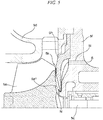
FIG. 3 is a cross-sectional diagram showing a main structure of the turbocharger of the embodiment of the present invention. -
FIG. 4A is a cross-sectional diagram showing a first modification of the main structure of the turbocharger of the embodiment of the present invention. -
FIG. 4B is a cross-sectional diagram showing a modification ofFIG. 4A . -
FIG. 5 is a cross-sectional diagram showing a second modification of the main structure of the turbocharger of the embodiment of the present invention. -
FIG. 6 is a system configuration diagram showing a modification of the pressurized incineration facility of the embodiment of the present invention. - Hereinafter, an embodiment of the present invention is described with reference to the drawings.
- As shown in
FIG. 1 , a pressurizedincineration facility 100 of this embodiment is configured including a pressurized-fluidized bed incinerator 1 (a pressurized incinerator), asupply device 2, anair filter 3, ablower 4, aturbocharger 5, a first on-off valve 6, a second on-off valve 7, a three-way valve 8 (a switching device), apreheater 9, first and second regulatingvalves dust collector 11, an exhaustgas treatment device 12, asmokestack 13 and the like. As shown inFIG. 1 , these components are connected to each other through pipes. - The pressurized-fluidized bed incinerator 1 is an approximately cylindrical incinerator. The pressurized-fluidized bed incinerator 1 obtains start-up air K supplied from the
blower 4 through the first and second regulatingvalves turbocharger 5 through the first and second regulatingvalves - The pressurized-fluidized bed incinerator 1 is adjunctively provided with a start-up apparatus which increases the temperature inside the pressurized-fluidized bed incinerator 1 at the time the pressurized
incineration facility 100 is started (at the time of start-up of the facility). The start-up apparatus is configured of anauxiliary fuel tank 1a, aheating burner 1b and the like. The start-up apparatus burns an auxiliary fuel together with the start-up air K inside the pressurized-fluidized bed incinerator 1, the auxiliary fuel having been supplied to theheating burner 1b from theauxiliary fuel tank 1a or from an auxiliary fuel supply source (not shown) of city gas or the like, and thereby increases the temperature inside the pressurized-fluidized bed incinerator 1 up to a predetermined temperature (for example, a temperature at which the processing object P spontaneously combusts). - The
supply device 2 is a device which supplies the pressurized-fluidized bed incinerator 1 with the processing object P received from outside of thesupply device 2, and is, for example, a screw conveyor or a pump. In addition, the processing object P being an incineration object of the pressurized-fluidized bed incinerator 1 is a combustible waste such as various kinds of biomass. - The
air filter 3 is a device which purifies air by removing dirt, dust or the like therefrom, and supplies a compressor of theturbocharger 5 with purified air obtained by purifying air in this way. - The
blower 4 is a device which operates only at the time of start-up of the facility similarly to the start-up apparatus of the pressurized-fluidized bed incinerator 1, and supplies the start-up air K to the pressurized-fluidized bed incinerator 1 at the time incineration of the processing object P is started by the pressurized-fluidized bed incinerator 1. - That is, since the pressurized-fluidized bed incinerator 1 is not in a normal combustion state at the time of start-up of the facility, the combustion exhaust gas G sufficient to drive the
turbocharger 5 is not supplied to a turbine of theturbocharger 5 from the pressurized-fluidized bed incinerator 1. Therefore, theturbocharger 5 cannot compress air supplied from the air filter 3 (to be described later), and cannot supply the compressed air A to the pressurized-fluidized bed incinerator 1. Theblower 4 in place of theturbocharger 5 at the time of start-up of the facility supplies the pressurized-fluidized bed incinerator 1 with the start-up air K obtained from outside air so that the start-up air K serves as the primary and secondary combustion air. Theblower 4 stops operating at a phase (after start-up of the facility) in which the start-up of the pressurizedincineration facility 100 finishes and the pressurizedincineration facility 100 enters a normal operation state. - The
turbocharger 5 compresses the purified air taken from theair filter 3 by being rotationally driven by the combustion exhaust gas G of the pressurized-fluidized bed incinerator 1, and thereby produces the compressed air A. Theturbocharger 5 is a rotary machine in which aturbine impeller 5a and acompressor impeller 5b are fixed to arotary shaft 5c. In theturbocharger 5, thecompressor impeller 5b is rotationally driven by a rotational driving force generated by the combustion exhaust gas G, which serves as a drive fluid, striking on theturbine impeller 5a, and the compressed air A is produced by rotation of thecompressor impeller 5b. Theturbocharger 5 supplies the compressed air A to the second on-off valve 7. - In more detail, as shown in
FIG. 2 , theturbocharger 5 is configured so that a rotor, in which theturbine impeller 5a and thecompressor impeller 5b are fixed and united to two ends of therotary shaft 5c, is rotatably accommodated in a housing having a predetermined shape. A rear surface 5a1 of theturbine impeller 5a and a rear surface 5b1 of thecompressor impeller 5b are disposed so as to face each other. In addition, for the sake of convenience,FIG. 2 shows a state where theturbocharger 5 shown inFIG. 1 is horizontally reversed, namely a state where theturbine impeller 5a is disposed on the left side ofFIG. 2 and thecompressor impeller 5b is disposed on the right side thereof. - As shown in
FIG. 2 , the housing of theturbocharger 5 is configured in which aturbine housing 5d accommodating theturbine impeller 5a and acompressor housing 5e accommodating thecompressor impeller 5b are fixed using screws to a bearinghousing 5f accommodating therotary shaft 5c in a state where the bearinghousing 5f is interposed between theturbine housing 5d and thecompressor housing 5e. The bearinghousing 5f also accommodates abearing mechanism 5g in addition to therotary shaft 5c, thebearing mechanism 5g rotatably supporting therotary shaft 5c. An oil flow passageway which supplies lubricating oil to thebearing mechanism 5g is formed in the bearinghousing 5f. - A
heat shield plate 5h, which limits transfer of heat of the combustion exhaust gas G to thebearing mechanism 5g, is interposed between theturbine housing 5d and the bearinghousing 5f. - The
heat shield plate 5h is an approximately circular plate-shaped member provided with an opening at the center of the member, therotary shaft 5c being inserted into the opening, and the outer peripheral part of theheat shield plate 5h is sandwiched between theturbine housing 5d and the bearinghousing 5f. - A scroll flow passageway 5d1 and a turbine nozzle 5d2 are formed in the
turbine housing 5d at a position radially outside of theturbine impeller 5a. In theturbine housing 5d, the combustion exhaust gas G passes through the scroll flow passageway 5d1 and the turbine nozzle 5d2, and strikes on theturbine impeller 5a from radially outside thereof, thereby generating a rotation force of theturbine impeller 5a. - A diffuser 5e1 and a scroll flow passageway 5e2 are formed in the
compressor housing 5e at a position radially outside of thecompressor impeller 5b. In thecompressor housing 5e, the purified air supplied from theair filter 3 flows from the front side (the right side inFIG. 2 ) of therotating compressor impeller 5b into thecompressor impeller 5b, thereby being discharged into the diffuser 5e1, and thereafter passes through the diffuser 5e1 and the scroll flow passageway 5e2, thereby becoming the compressed air A. - As shown in
FIGS. 2 and3 , theturbocharger 5 is provided with a sealgas flow passageway 5i which supplies seal gas S to the rear surface 5a1 of theturbine impeller 5a. That is, the sealgas flow passageway 5i supplies the seal gas S into a space between the rear surface 5a1 of theturbine impeller 5a and the housing (theheat shield plate 5h) of theturbocharger 5. As shown inFIGS. 2 and3 , the sealgas flow passageway 5i is configured including a flow passageway, which is formed in the bearinghousing 5f and in which one end thereof is connected to an output port (a discharge port) of the three-way valve 8, and a gap formed between the bearinghousing 5f and theheat shield plate 5h. The other end (front end part) of the sealgas flow passageway 5i is a jetting port N for the seal gas S, the jetting port N being formed of a gap between the bearinghousing 5f and theheat shield plate 5h. - The jetting port N opens at the housing facing the rear surface 5a1 of the
turbine impeller 5a. That is, the other end of the sealgas flow passageway 5i is a small-width nozzle which opens in a circular-annular pattern around therotary shaft 5c. The jetting port N is formed in a circular pattern coaxial with theturbine impeller 5a. - As shown in
FIG. 3 , a cross-sectional shape of the jetting port N along the central axis of therotary shaft 5c is curved toward the outer periphery of theturbine impeller 5a so that the jetting port N jets the seal gas S to the rear surface 5a1 of theturbine impeller 5a toward the outer periphery of theturbine impeller 5a. The seal gas S jetted from the jetting port N to the rear surface 5a1 of theturbine impeller 5a toward the outer periphery thereof forms a continuous gas film around therotary shaft 5c on the rear surface 5a1 of theturbine impeller 5a. Thus, the seal gas S can limit or prevent inflow of the combustion exhaust gas G into thebearing mechanism 5g supporting therotary shaft 5c, the combustion exhaust gas G having flowed to the rear surface 5a1 of theturbine impeller 5a. - It is to be noted that since the inflow of the combustion exhaust gas G into the
bearing mechanism 5g is prevented by a continuous gas film formed at least around therotary shaft 5c, the seal gas S need not be jetted toward the outer periphery of theturbine impeller 5a. For example, the seal gas S may be jetted to the rear surface 5a1 of theturbine impeller 5a in a direction approximately perpendicular to the rear surface 5a1. In some cases, the seal gas S may be jetted inward slightly (toward the rotation center) of theturbine impeller 5a. - In order to form a gas film capable of stably countering the inflow of the combustion exhaust gas G, it is preferable that the facing distance (for example, the distance in the central axis direction of the
rotary shaft 5c) between the jetting port N and the rear surface 5a1 of theturbine impeller 5a be as small as possible. For example, the shapes of the bearinghousing 5f and theheat shield plate 5h may be changed so that the facing distance is decreased. Because of intervention of the three-way valve 8, the sealgas flow passageway 5i is supplied with part of the start-up air K at the time of start-up of the facility so that the start-up air K serves as the seal gas S, and on the other hand, is supplied with part of the compressed air A after start-up of the facility so that the compressed air A serves as the seal gas S. - As shown in
FIG. 1 , the first on-off valve 6 is provided in a discharge-side pipe of theblower 4. The first on-off valve 6 is set to be completely opened at the time of start-up of the facility, and on the other hand, is set to be completely closed after start-up of the facility. - As shown in
FIG. 1 , the second on-off valve 7 is provided in a pipe connected to an outlet of the compressor of theturbocharger 5, namely in the pipe connected to an outlet of the scroll flow passageway 5e2. The second on-off valve 7 is set to be completely closed at the time of start-up of the facility, and on the other hand, is set to be completely opened after start-up of the facility. That is, at the time of start-up of the facility, only the start-up air K discharged from theblower 4 is supplied to thepreheater 9 through pipes. - The three-
way valve 8 is a switching device including two input ports and one output port, and selects one from the two input ports and connects one to the output port. As shown inFIGS. 1 and2 , in the three-way valve 8, one input port is connected to theblower 4, and the other input port is connected to the outlet (namely, the outlet of the scroll flow passageway 5e2) of the compressor of theturbocharger 5. In addition, the output port of the three-way valve 8 is connected to one end (the rear end) of the sealgas flow passageway 5i. At the time of start-up of the facility, the three-way valve 8 selects the one input port and thereby supplies the sealgas flow passageway 5i with the start-up air K supplied from theblower 4. On the other hand, after start-up of the facility, the three-way valve 8 selects the other input port and thereby supplies the sealgas flow passageway 5i with the compressed air A supplied from theturbocharger 5. - In the
pressurized incineration facility 100, the three-way valve 8 and the sealgas flow passageway 5i of theturbocharger 5 constitute a seal device which obtains the start-up air K or the compressed air A and which jets out the air to the rear surface 5a1 of theturbine impeller 5a so that the air serves as the seal gas S. In addition, theblower 4 and theturbocharger 5 also serve as a gas supply source in thepressurized incineration facility 100. - The
preheater 9 is provided between the first and second on-off valves 6 and 7 and the first andsecond regulating valves preheater 9 is a heat exchanger which increases the temperature of the start-up air K supplied from the blower 4 (at the time of start-up of the facility) or of the compressed air A supplied from the turbocharger 5 (after start-up of the facility) by using the combustion exhaust gas G supplied from the pressurized-fluidized bed incinerator 1. The temperature of the compressed air A is increased by compression operation of thecompressor impeller 5b so as to be higher than the temperature (approximately equal to the atmospheric temperature) of the purified air. Thepreheater 9 further increases the temperature of the start-up air K or of the compressed air A by exchanging heat between the high-temperature combustion exhaust gas G and the start-up air K or the compressed air A, and thereafter supplies the start-up air K or the compressed air A to the first andsecond regulating valves preheater 9 discharges into thedust collector 11, the combustion exhaust gas G whose temperature has been decreased through heat exchange with the start-up air K or with the compressed air A. - The
first regulating valve 10A is a first control valve which regulates the flow volume of the compressed air A (or the start-up air K) to be supplied to the bottom of the pressurized-fluidized bed incinerator 1 so that the air serves as the primary combustion air. On the other hand, thesecond regulating valve 10B is a second control valve which regulates the flow volume of the compressed air A (or the start-up air K) to be supplied to a position of the pressurized-fluidized bed incinerator 1 so that the air serves as the secondary combustion air, the position being higher in the vertical direction than a position to which the primary combustion air is supplied. The first andsecond regulating valves - The
dust collector 11 is a device which separates and removes solids such as dust from the combustion exhaust gas G supplied from thepreheater 9, and is, for example, a bug filter. Thedust collector 11 supplies the turbine of theturbocharger 5 with the high-temperature combustion exhaust gas G from which the solids have been separated and removed. The combustion exhaust gas G acts on theturbine impeller 5a, whereby the pressure and temperature of the combustion exhaust gas G are decreased, and thereafter the combustion exhaust gas G is supplied to the exhaustgas treatment device 12. - The exhaust
gas treatment device 12 is a device which removes impurities such as sulfur component or nitrogen component from the combustion exhaust gas G supplied from thedust collector 11, and supplies thesmokestack 13 with exhaust gas purified by removing the impurities. Thesmokestack 13 is a well-known cylindrical construct having a predetermined height, and releases exhaust gas into the atmosphere from a predetermined height, the exhaust gas being supplied from the exhaustgas treatment device 12. - Next, the operation of the
pressurized incineration facility 100, particularly the operation of the seal device being a distinctive component in thepressurized incineration facility 100, is described in detail. - First, the operation of the
pressurized incineration facility 100 at the time of start-up (at the time of start-up of the facility) is described. At the time of start-up of the facility, the first on-off valve 6 is set to be completely opened, the second on-off valve 7 is set to be completely closed, and the three-way valve 8 being the switching device is set so as to select the one input port thereof. Theblower 4 operates in this state, whereby most of the start-up air K discharged from theblower 4 is supplied to the pressurized-fluidized bed incinerator 1, and part of the start-up air K is supplied to the sealgas flow passageway 5i of theturbocharger 5 through the three-way valve 8. - That is, the start-up air K discharged from the
blower 4 is supplied to the first andsecond regulating valves preheater 9, the flow volume of the start-up air K is finally regulated by the first andsecond regulating valves heating burner 1b. The pressurized-fluidized bed incinerator 1 takes the start-up air K therein so that the start-up air K serves as the first and second combustion air, and the start-up apparatus burns fuel (auxiliary fuel) by using the first and second combustion air serving as an oxidizer, thereby gradually increasing the temperature inside the incinerator. - When the temperature inside the pressurized-fluidized bed incinerator 1 is increased up to a predetermined temperature (for example, a temperature at which the processing object P spontaneously combusts), the
supply device 2 operates and supplies the processing object P thereinto, and thereby the pressurized-fluidized bed incinerator 1 starts an incineration process (combustion process) of the processing object P. When the incineration process of the processing object P is started, the combustion exhaust gas G of a volume sufficient to drive theturbocharger 5 is generated inside the pressurized-fluidized bed incinerator 1. The combustion exhaust gas G is supplied from the pressurized-fluidized bed incinerator 1 to the turbine of theturbocharger 5 via thepreheater 9 and thedust collector 11. As a result, theturbocharger 5 is rotationally driven by the combustion exhaust gas G supplied from the pressurized-fluidized bed incinerator 1. - When the
turbocharger 5 reaches a state of being rotationally driven by the combustion exhaust gas G in this way, the operation of theblower 4 is stopped, the first on-off valve 6 is set to be completely closed, the second on-off valve 7 is set to be completely opened, and the three-way valve 8 is set so as to select the other input port thereof. As a result, thepressurized incineration facility 100 changes from a facility start-up state (the time of start-up of the facility) to a normal operation state (after start-up of the facility). - After start-up of the facility, the combustion exhaust gas G, from which solids have been separated and removed at the
dust collector 11, is supplied to theturbocharger 5, and the compressed air A supplied from theturbocharger 5 is preheated by thepreheater 9. The combustion exhaust gas G which has been used for driving theturbocharger 5 is supplied from theturbocharger 5 to the exhaustgas treatment device 12, impurities of the combustion exhaust gas G are removed, and thereafter the exhaust gas is released from thesmokestack 13 into the atmosphere. In addition, the compressed air A, which has been preheated by thepreheater 9 and thereafter whose flow volume has been regulated by the first andsecond regulating valves - The above description shows the overall operation of the
pressurized incineration facility 100, and thepressurized incineration facility 100 performs distinctive operations described below at the time of start-up of the facility and after start-up of the facility. - That is, at the time of start-up of the facility, part of the start-up air K is supplied to the seal
gas flow passageway 5i of theturbocharger 5 through the three-way valve 8, and is jetted to the rear surface 5a1 of theturbine impeller 5a toward the outer periphery of theturbine impeller 5a from the jetting port N positioned at the front end of the sealgas flow passageway 5i so that the start-up air K serves as the seal gas S. Thus, part of the start-up air K is supplied into a space between the rear surface 5a1 of theturbine impeller 5a and the housing (theheat shield plate 5h) of theturbocharger 5 so that the start-up air K serves as the seal gas S. The seal gas S (the start-up air K) forms a continuous gas film around therotary shaft 5c on the rear surface 5a1 of theturbine impeller 5a. - Since the second on-off valve 7 is set to be completely closed at the time of start-up of the facility, part of the start-up air K discharged from the
blower 4 is prevented from being supplied to the outlet of the compressor of theturbocharger 5 and from giving disturbance to the compressor of theturbocharger 5. In addition, since the three-way valve 8 is set so as to select the one input port at the time of start-up of the facility, the sealgas flow passageway 5i is not supplied with discharged air of the compressor of theturbocharger 5 having an insufficient pressure because the rotation speed of theturbocharger 5 does not reach a normal rotation speed but is supplied with the start-up air K provided with a predetermined flow velocity by theblower 4. - As a result, the combustion exhaust gas G which has flowed to the rear surface 5a1 of the
turbine impeller 5a cannot flow into the vicinity of therotary shaft 5c due to the gas film formed by the seal gas S (the start-up air K), and thus cannot flow into thebearing mechanism 5g supporting therotary shaft 5c inside the bearinghousing 5f. Therefore, since the combustion exhaust gas G can be prevented from contacting the lubricating oil of thebearing mechanism 5g, deterioration of the lubricating oil can be prevented at the time of start-up of the facility. - On the other hand, after start-up of the facility, the seal
gas flow passageway 5i is supplied through the three-way valve 8 with part of the compressed air A discharged from the compressor of theturbocharger 5 instead of part of the start-up air K discharged from theblower 4. The compressed air A has a sufficient pressure because the compressed air A is gas discharged from the compressor of theturbocharger 5 which normally rotates. The compressed air A is jetted from the jetting port N to the rear surface 5a1 of theturbine impeller 5a toward the outer periphery of theturbine impeller 5a so that the compressed air A serves as the seal gas S. That is, part of the compressed air A is supplied into a space between the rear surface 5a1 of theturbine impeller 5a and the housing (theheat shield plate 5h) of theturbocharger 5 so that the compressed air A serves as the seal gas S. The seal gas S (the compressed air A) forms a continuous gas film around therotary shaft 5c on the rear surface 5a1 of theturbine impeller 5a. - As a result, the combustion exhaust gas G which has flowed to the rear surface 5a1 of the
turbine impeller 5a cannot flow into the vicinity of therotary shaft 5c due to the gas film formed by the seal gas S (the compressed air A), and thus cannot flow into thebearing mechanism 5g supporting therotary shaft 5c inside the bearinghousing 5f. Therefore, since contact of the combustion exhaust gas G with the lubricating oil of thebearing mechanism 5g can be prevented by the seal gas S (the compressed air A), deterioration of the lubricating oil can also be prevented after start-up of the facility. - The pressure of the start-up air K used as the seal gas S at the time of start-up of the facility may be lower than that of the compressed air A at the time of the normal operation of the
turbocharger 5. However, the pressure of the combustion exhaust gas G at the time of start-up of the facility is lower than the pressure of the combustion exhaust gas G at the time of the normal operation. That is, the jetting pressure required of the seal gas S at the time of start-up of the facility is lower than the jetting pressure required of the seal gas S at the time of the normal operation. Therefore, if the start-up air K is jetted to the rear surface 5a1 of theturbine impeller 5a at the time of start-up of the facility so that the start-up air K serves as the seal gas S, the combustion exhaust gas G can be sufficiently prevented from flowing into thebearing mechanism 5g. - As described above, in this embodiment, the start-up air K is used as the seal gas S at the time of start-up of the facility, and the compressed air A is used as the seal gas S after start-up of the facility. That is, in this embodiment, at the time of start-up of the facility, inflow of the combustion exhaust gas G into the
bearing mechanism 5g is prevented by using theblower 4 as the supply source of the seal gas S, and after start-up of the facility, inflow of the combustion exhaust gas G into thebearing mechanism 5g is prevented by using theturbocharger 5 as the supply source of the seal gas S. According to this embodiment, inflow of the combustion exhaust gas G into thebearing mechanism 5g can be prevented in both cases at the time of start-up of the facility and after start-up of the facility, and thereby deterioration of the lubricating oil can be limited. - Hereinbefore, the preferable embodiment of the present invention is described with reference to the attached drawings, but the present invention is not limited to this embodiment. The shape, the combination or the like of each component shown in the above embodiment is merely an example, and additions, omissions, replacements, and other modifications of configurations based on design requests or the like can be adopted within the scope of and not departing from the gist of the present invention. For example, the following modifications can be proposed.
- (1) In the above embodiment, the start-up air K is used as the seal gas S at the time of start-up of the facility, and the compressed air A is used as the seal gas S after start-up of the facility (during the normal operation), but the present invention is not limited thereto. For example, in a case where a separately prepared air supply source (for example, a compressor) is used, the air supply source may be used at the time of start-up instead of a start-up blower, and may be switched to a turbocharger after start-up so that the turbocharger supplies air serving as seal gas. In addition, at the time of start-up, a start-up blower may supply air serving as seal gas, and after start-up, may be switched to a separately prepared air supply source. Furthermore, a separately prepared air supply source may be used in both cases at the time of start-up and after start-up.
- (2) In the above embodiment, the seal gas S is not only jetted to the rear surface 5a1 of the
turbine impeller 5a at the time after start-up in which the pressurized incineration facility is in the normal operation state but is also jetted thereto at the time of start-up of the facility, but the present invention is not limited thereto. Since the amount of the combustion exhaust gas G generated at the time of start-up of the facility is small and the pressure thereof is low, the combustion exhaust gas G has a low potential to flow into thebearing mechanism 5g. In view of this point, it is conceivable that jetting of the seal gas S is not performed at the time of start-up of the facility. In this case, since it is only necessary to supply the compressed air A to the sealgas flow passageway 5i after start-up of the facility, the three-way valve 8 may be omitted, and discharged air of the compressor of theturbocharger 5 may be directly supplied to the sealgas flow passageway 5i. That is, the seal device in this case includes as a main component, theturbocharger 5 including the sealgas flow passageway 5i. - (3) In the above embodiment, only one annular jetting port N is provided facing the rear surface 5a1 of the
turbine impeller 5a, but the present invention is not limited thereto. For example, as shown inFIGS. 4A and 4B , theheat shield plate 5h may be composed of three unit plates 5h1, 5h2 and 5h3, and thereby three flow passageways (branching flow passageways) 5i1, 5i2 and 5i3 may be provided so that the jetting ports of the three flow passageways face the rear surface 5a1 of theturbine impeller 5a.
That is, as shown inFIG. 4A , a first flow passageway 5i1 which supplies the seal gas S to the rear surface 5a1 of theturbine impeller 5a is formed by the bearinghousing 5f and the first unit plate 5h1, a second flow passageway (branching flow passageway) 5i2 communicating with the first flow passageway 5i1 is formed by the first and second unit plates 5h1 and 5h2, and a third flow passageway (branching flow passageway) 5i3 communicating with the second flow passageway 5i2 is formed by the second and third unit plates 5h2 and 5h3. The front end parts of the first to third flow passageways 5i1 to 5i3 are small-width jetting ports N1 to N3 (nozzles) provided in a triple annular pattern around therotary shaft 5c. Each of the jetting ports N1 to N3 is disposed in a circular pattern coaxial with theturbine impeller 5a.
As shown inFIGS. 4A and 4B , the first flow passageway 5i1 is formed of a gap between the bearinghousing 5f and the first unit plate 5h1. The second flow passageway 5i2 is formed of a through-hole formed in the first unit plate 5h1 and of a gap between the first and second unit plates 5h1 and 5h2. The third flow passageway 5i3 is formed of a through-hole formed in the second unit plate 5h2 and of a gap between the second and third unit plates 5h2 and 5h3. Since a triple gas seal is formed around therotary shaft 5c by providing the three jetting ports N1 to N3, it is possible to further reliably prevent the combustion exhaust gas G from flowing into thebearing mechanism 5g and from affecting the lubricating oil.
FIG. 4A shows a state where the three jetting ports N1 to N3 are formed so that all the three jetting ports N1 to N3 jet the seal gas S to the rear surface 5a1 of theturbine impeller 5a in a direction approximately perpendicular to the rear surface 5a1. However, for example, as shown inFIG. 4B , two jetting ports N1A and N2A close to therotary shaft 5c may be formed so as to jet the seal gas S toward the outer periphery of theturbine impeller 5a. - (4) In the above embodiment, only one annular jetting port N is provided facing the rear surface 5a1 of the
turbine impeller 5a, but the present invention is not limited thereto. For example, as shown inFIG. 5 , alabyrinth seal 5k is added to part of theheat shield plate 5h closest to theturbine impeller 5a, and thereby thelabyrinth seal 5k and the gas seal formed by the seal gas S can further reliably prevent the combustion exhaust gas G from flowing into thebearing mechanism 5g and from affecting the lubricating oil. - (5) In the above embodiment, the outlet of the
blower 4 is connected to the outlet of the compressor of theturbocharger 5, but the present invention is not limited thereto. For example, a configuration shown inFIG. 6 may be adopted in which theblower 4 is interposed between the inlet of the compressor of theturbocharger 5 and theair filter 3, a second on-offvalve 7A and a third on-offvalve 14A are provided between the outlet of theblower 4 and the inlet of the compressor of theturbocharger 5, a bypass pipe connects the inlet and the outlet of the compressor of theturbocharger 5, and the bypass pipe is provided with a first on-offvalve 6A. Additionally, inFIG. 6 , a second bypass pipe connects theair filter 3 and theturbocharger 5 so as to bypass theblower 4, the second bypass pipe is provided with a fourth on-offvalve 14B, and a fifth on-offvalve 8A and a sixth on-offvalve 8B are adopted instead of the three-way valve 8.
In apressurized incineration facility 200 having the above configuration, at the time of start-up of the facility, the first and third on-offvalves valves valve 8A is completely closed, and the sixth on-offvalve 8B is completely opened. Theblower 4 operates in this state, whereby most of the start-up air K discharged from theblower 4 is supplied to the pressurized-fluidized bed incinerator 1 through the first on-offvalve 6A, and part of the start-up air K is supplied to the sealgas flow passageway 5i of theturbocharger 5 through the sixth on-offvalve 8B. The start-up air K is jetted to the rear surface 5a1 of theturbine impeller 5a through the sealgas flow passageway 5i so that the start-up air K serves as the seal gas S, and prevents the combustion exhaust gas G from flowing into thebearing mechanism 5g.
On the other hand, after start-up of the facility, theblower 4 stops operating, the first and third on-offvalves valves valve 8A is completely opened, and the sixth on-offvalve 8B is completely closed. As a result, theturbocharger 5 rotationally driven by the combustion exhaust gas G produces the compressed air A by inhaling purified air supplied from theair filter 3 without intervention of theblower 4, and supplies the compressed air A to the pressurized-fluidized bed incinerator 1. In addition, part of the compressed air A is supplied to the sealgas flow passageway 5i of theturbocharger 5 through the fifth on-offvalve 8A, and is jetted to the rear surface 5a1 of theturbine impeller 5a through the sealgas flow passageway 5i so that the compressed air A serves as the seal gas S, thereby preventing the combustion exhaust gas G from flowing into thebearing mechanism 5g.
In thepressurized incineration facility 200, similarly to the above embodiment, since the start-up air K or the compressed air A is also jetted to the rear surface 5a1 of theturbine impeller 5a so as to serve as the seal gas S, inflow of the combustion exhaust gas G into thebearing mechanism 5g can be prevented, and thus deterioration of the lubricating oil can be limited.
Additionally, in thepressurized incineration facility 100 of the above embodiment, the fifth and sixth on-offvalves pressurized incineration facility 200 may be adopted instead of the three-way valve 8. That is, the fifth and sixth on-offvalves - (6) In the above embodiment, the pressurized-fluidized bed incinerator 1 is used, but the pressurized incinerator of the present invention is not limited to an incinerator having a fluidized bed, and another type of pressurized incinerator may be adopted.
- (7) As described above, although the discharge amount of the combustion exhaust gas G discharged from the pressurized-fluidized bed incinerator 1 at the time of start-up of the facility is generally less than the discharge amount thereof at the time of the normal operation, the discharge amount of the combustion exhaust gas G discharged from the pressurized-fluidized bed incinerator 1 at the time of the normal operation may also vary in accordance with the processing amount of the processing object P, or the like. It is considered that the flow volume of the compressed air A discharged from the
turbocharger 5, namely the flow volume of the seal gas S, varies in proportion to the flow volume of the combustion exhaust gas G supplied to theturbocharger 5, and it may be preferable that the flow volume of the jetted seal gas S be regulated in order that the seal gas S does not influence the turbine efficiency of theturbocharger 5. In this case, a flow volume-regulating device (regulating valve) may be provided at a position of a flow passageway from the three-way valve 8 to the jetting port N. In addition, a controller or the like may be provided which controls the flow volume-regulating device based on information of the processing amount of the pressurized-fluidized bed incinerator 1, the discharge amount of the combustion exhaust gas G, the rotation speed of theturbocharger 5, or the like. - The present invention can be applied to a pressurized incineration facility and a pressurized incineration method used to incinerate a processing object under a pressure increased by compressed air.
-
- 1
- pressurized-fluidized bed incinerator (pressurized incinerator)
- 2
- supply device
- 3
- air filter
- 4
- blower
- 5
- turbocharger
- 5a
- turbine impeller
- 5a1
- rear surface
- 5b
- compressor impeller
- 5c
- rotary shaft
- 5d
- turbine housing
- 5e
- compressor housing
- 5f
- bearing housing
- 5g
- bearing mechanism
- 5h
- heat shield plate
- 5i
- seal gas flow passageway (seal device)
- 6
- first on-off valve
- 7
- second on-off valve
- 8
- three-way valve (switching device)
- 8A
- fifth on-off valve
- 8B
- sixth on-off valve
- 9
- preheater
- 10A
- first regulating valve
- 10B
- second regulating valve
- 11
- dust collector
- 12
- exhaust gas treatment device
- 13
- smokestack
- 14A
- third on-off valve
- 14B
- fourth on-off valve
- 100, 200
- pressurized incineration facility
- A
- compressed air
- G
- combustion exhaust gas
- K
- start-up air
- P
- processing object
- S
- seal gas
- N
- jetting port
Claims (8)
- A pressurized incineration facility (100) comprising:a pressurized incinerator (1) which incinerates a processing object (P) under a pressure increased by compressed air (A);a turbocharger (5) which produces the compressed air by being rotationally driven by combustion exhaust gas (G) from the pressurized incinerator (1);characterized by a seal device which jets seal gas (S) to a rear surface of a turbine impeller (5a) of the turbocharger (5).
- The pressurized incineration facility (100) according to claim 1, further comprising:a blower (4) which supplies start-up air to the pressurized incinerator (1) at the time of start-up of the facility,wherein the seal device is configured to obtain the start-up air (K) of the blower (4) at the time of start-up of the facility (100) and to jet the start-up air (K) to the rear surface of the turbine impeller (5a) so that the start-up air (K) serves as the seal gas (5), and is configured to obtain the compressed air (A) of the turbocharger (5) after start-up of the facility (100) and to jet the compressed air (A) to the rear surface of the turbine impeller (5a) so that the compressed air (A) serves as the seal gas (5).
- The pressurized incineration facility (100) according to claim 2,
wherein the seal device includes:a switching device (8) which selects and discharges the start-up air (K) at the time of start-up of the facility (100), and which selects and discharges the compressed air (A) after start-up of the facility (100); anda seal gas flow passageway provided in the turbocharger (5), one end of the seal gas flow passageway (5i) being connected to a discharge port of the switching device (8), and another end of the seal gas flow passageway (5i) opening at a housing facing the rear surface of the turbine impeller (5a). - The pressurized incineration facility (100) according to claim 1,
wherein the seal device includes a seal gas flow passageway (5i) which is provided in the turbocharger (5) and which guides the compressed air (A) to a housing facing the rear surface of the turbine impeller (5a) so that the compressed air (A) serves as the seal gas. - The pressurized incineration facility (100) according to any one of claims 1 to 4,
wherein the seal device includes a plurality of jetting ports which jet the seal gas (5) to a plurality of parts of the rear surface of the turbine impeller (5a). - The pressurized incineration facility (100) according to any one of claims 1 to 5,
wherein the seal device includes a jetting port which jets the seal gas (5) to the rear surface of the turbine impeller toward an outer periphery of the turbine impeller (5a). - The pressurized incineration facility (100) according to any one of claims 1 to 6,
wherein the seal device includes a jetting port which jets the seal gas (S) in a circular pattern coaxial with the turbine impeller (5a) to the rear surface of the turbine impeller (5a). - A pressurized incineration method comprising steps of:incinerating a processing object under a pressure increased by supplying a pressurized incinerator (1) with compressed air (A) produced by a turbocharger (5);producing the compressed air (A) by rotationally driving the turbocharger (5) by combustion exhaust gas (6) of the pressurized incinerator (1);characterized by jetting seal gas (S) to a rear surface of a turbine impeller of the turbocharger (5).
Applications Claiming Priority (2)
| Application Number | Priority Date | Filing Date | Title |
|---|---|---|---|
| JP2013015556A JP6030462B2 (en) | 2013-01-30 | 2013-01-30 | Pressure incineration equipment and pressure incineration method |
| PCT/JP2014/051632 WO2014119499A1 (en) | 2013-01-30 | 2014-01-27 | Pressurized incineration equipment and pressurized incineration method |
Publications (3)
| Publication Number | Publication Date |
|---|---|
| EP2952807A1 EP2952807A1 (en) | 2015-12-09 |
| EP2952807A4 EP2952807A4 (en) | 2016-09-21 |
| EP2952807B1 true EP2952807B1 (en) | 2017-06-28 |
Family
ID=51262214
Family Applications (1)
| Application Number | Title | Priority Date | Filing Date |
|---|---|---|---|
| EP14746349.1A Active EP2952807B1 (en) | 2013-01-30 | 2014-01-27 | Pressurized incineration equipment and pressurized incineration method |
Country Status (6)
| Country | Link |
|---|---|
| US (1) | US9982552B2 (en) |
| EP (1) | EP2952807B1 (en) |
| JP (1) | JP6030462B2 (en) |
| KR (1) | KR102087675B1 (en) |
| CN (1) | CN104969002B (en) |
| WO (1) | WO2014119499A1 (en) |
Families Citing this family (8)
| Publication number | Priority date | Publication date | Assignee | Title |
|---|---|---|---|---|
| EP3434875B1 (en) * | 2016-03-30 | 2021-05-26 | Mitsubishi Heavy Industries Engine & Turbocharger, Ltd. | Turbocharger |
| JP2018159481A (en) * | 2017-03-22 | 2018-10-11 | メタウォーター株式会社 | Incinerator with supercharger and operation method thereof |
| CN107178785A (en) * | 2017-07-28 | 2017-09-19 | 贵州富燃环保科技有限公司 | A kind of circulating fluid bed garbage furnace |
| US12460727B2 (en) * | 2019-09-20 | 2025-11-04 | Rtx Corporation | Self-centering seal and method of using same |
| WO2021199308A1 (en) * | 2020-03-31 | 2021-10-07 | 三菱重工エンジン&ターボチャージャ株式会社 | Turbocharger |
| CN114776403B (en) * | 2021-12-29 | 2023-12-26 | 东方电气集团东方汽轮机有限公司 | An air inlet structure and method suitable for turbines with large enthalpy drop and small flow rate |
| US12516611B2 (en) * | 2023-05-25 | 2026-01-06 | Borgwarner Inc. | Turbocharger bearing housing |
| WO2025128167A1 (en) * | 2023-12-15 | 2025-06-19 | Florida State University Research Foundation, Inc. | Method for providing a rotating shaft into a high pressure, high temperature furnace |
Family Cites Families (20)
| Publication number | Priority date | Publication date | Assignee | Title |
|---|---|---|---|---|
| US3818846A (en) * | 1972-04-26 | 1974-06-25 | Combustion Power | Method and apparatus for liquid disposal in a fluid bed reactor |
| EP0131736B1 (en) * | 1983-06-29 | 1987-01-21 | BBC Brown Boveri AG | Axial turbine for a turbo charger |
| JPS60173316A (en) | 1984-02-17 | 1985-09-06 | Nissan Motor Co Ltd | Gas bearing service for turbocharger |
| US4722663A (en) * | 1986-02-04 | 1988-02-02 | Rotoflow Corporation | Seal-off mechanism for rotating turbine shaft |
| JPS63106326A (en) | 1986-10-24 | 1988-05-11 | Isuzu Motors Ltd | Sealing device for exhaust turbine |
| JPH07119477A (en) * | 1993-10-20 | 1995-05-09 | Toyota Motor Corp | Supercharger seal device |
| JPH108903A (en) * | 1996-06-24 | 1998-01-13 | Nissan Motor Co Ltd | Structure of ceramic gas turbine |
| JP4062811B2 (en) | 1999-03-11 | 2008-03-19 | 株式会社Ihi | Gas seal device for variable capacity turbocharger |
| GB2348695A (en) * | 1999-04-06 | 2000-10-11 | James Engineering | Gas turbines |
| JP4274659B2 (en) | 2000-01-18 | 2009-06-10 | 三菱重工業株式会社 | Turbocharger |
| JP4247082B2 (en) * | 2003-09-26 | 2009-04-02 | 三菱重工業株式会社 | Turbocharger |
| JP4991986B2 (en) * | 2006-07-25 | 2012-08-08 | 独立行政法人土木研究所 | Pressure incinerator equipment and its startup method |
| JP2009174442A (en) * | 2008-01-25 | 2009-08-06 | Toyota Motor Corp | Turbocharger |
| US8096747B2 (en) * | 2008-02-01 | 2012-01-17 | General Electric Company | Apparatus and related methods for turbine cooling |
| JP5125684B2 (en) | 2008-03-28 | 2013-01-23 | 株式会社Ihi | Turbocharger |
| JP5401302B2 (en) * | 2009-12-28 | 2014-01-29 | 三機工業株式会社 | Operating method of pressurized fluidized incinerator and pressurized fluidized incinerator equipment |
| JP5422480B2 (en) * | 2010-05-10 | 2014-02-19 | 三菱重工業株式会社 | Sealing air introducing means for supercharger, supercharger equipped with the same, supercharger system equipped with the same, diesel engine equipped with the same, and ship equipped with the same |
| JP5449062B2 (en) * | 2010-07-02 | 2014-03-19 | 三菱重工業株式会社 | Seal air supply device for exhaust gas turbocharger |
| GB2489531B (en) * | 2011-04-02 | 2017-02-01 | Cummins Ltd | A turbocharger |
| US8915708B2 (en) * | 2011-06-24 | 2014-12-23 | Caterpillar Inc. | Turbocharger with air buffer seal |
-
2013
- 2013-01-30 JP JP2013015556A patent/JP6030462B2/en active Active
-
2014
- 2014-01-27 CN CN201480006292.8A patent/CN104969002B/en active Active
- 2014-01-27 US US14/764,365 patent/US9982552B2/en active Active
- 2014-01-27 EP EP14746349.1A patent/EP2952807B1/en active Active
- 2014-01-27 KR KR1020157023124A patent/KR102087675B1/en active Active
- 2014-01-27 WO PCT/JP2014/051632 patent/WO2014119499A1/en not_active Ceased
Also Published As
| Publication number | Publication date |
|---|---|
| US9982552B2 (en) | 2018-05-29 |
| WO2014119499A1 (en) | 2014-08-07 |
| US20150369474A1 (en) | 2015-12-24 |
| KR20150114515A (en) | 2015-10-12 |
| JP2014145343A (en) | 2014-08-14 |
| CN104969002A (en) | 2015-10-07 |
| KR102087675B1 (en) | 2020-03-11 |
| JP6030462B2 (en) | 2016-11-24 |
| EP2952807A4 (en) | 2016-09-21 |
| EP2952807A1 (en) | 2015-12-09 |
| CN104969002B (en) | 2017-03-08 |
Similar Documents
| Publication | Publication Date | Title |
|---|---|---|
| US9982552B2 (en) | Pressurized incineration facility and pressurized incineration method | |
| EP2123863B1 (en) | Pre-diffuser for centrifugal compressor | |
| EP2365189B1 (en) | Steam turbine system including valve for leak off line for controlling seal steam flow | |
| US8966878B2 (en) | Gas turbine | |
| US9828887B2 (en) | Power generation system having compressor creating excess air flow and turbo-expander to increase turbine exhaust gas mass flow | |
| CN105986899B (en) | Power generation system with a compressor creating excess air flow and a turboexpander utilizing the same | |
| US20160273409A1 (en) | Power generation system having compressor creating excess air flow and turbo-expander for supplemental generator | |
| US20160273408A1 (en) | Power generation system having compressor creating excess air flow and eductor for augmenting same | |
| US20160273397A1 (en) | Power generation system having compressor creating excess air flow and supplemental compressor therefor | |
| US9822670B2 (en) | Power generation system having compressor creating excess air flow and turbo-expander for cooling inlet air | |
| EP3070300B1 (en) | Power generation system having compressor creating excess air flow and cooling fluid injection therefor | |
| US9863285B2 (en) | Power generation system having compressor creating excess gas flow for supplemental gas turbine system | |
| US20160273407A1 (en) | Power generation system having compressor creating excess air flow and burner module therefor | |
| US8196408B2 (en) | System and method for distributing fuel in a turbomachine | |
| WO2018110476A1 (en) | Gas turbine engine and method for controlling same | |
| US20160273403A1 (en) | Power generation system having compressor creating excess air flow and turbo-expander using same | |
| US20160273401A1 (en) | Power generation system having compressor creating excess air flow and eductor for process air demand | |
| US7937929B2 (en) | Exhaust duct with bypass channel | |
| CN106537043B (en) | gas turbine | |
| JP2011017326A (en) | Variable displacement turbocharger | |
| JP2017223215A (en) | Dry vacuum pump with detoxification function | |
| JP6218095B2 (en) | Pressure incinerator | |
| WO2004097178A3 (en) | Intermittent gas-turbine engine | |
| US20160273394A1 (en) | Power generation system having compressor creating excess air flow and eductor augmentation |
Legal Events
| Date | Code | Title | Description |
|---|---|---|---|
| PUAI | Public reference made under article 153(3) epc to a published international application that has entered the european phase |
Free format text: ORIGINAL CODE: 0009012 |
|
| 17P | Request for examination filed |
Effective date: 20150729 |
|
| AK | Designated contracting states |
Kind code of ref document: A1 Designated state(s): AL AT BE BG CH CY CZ DE DK EE ES FI FR GB GR HR HU IE IS IT LI LT LU LV MC MK MT NL NO PL PT RO RS SE SI SK SM TR |
|
| AX | Request for extension of the european patent |
Extension state: BA ME |
|
| DAX | Request for extension of the european patent (deleted) | ||
| A4 | Supplementary search report drawn up and despatched |
Effective date: 20160822 |
|
| RIC1 | Information provided on ipc code assigned before grant |
Ipc: F01D 11/04 20060101ALI20160816BHEP Ipc: F23C 10/18 20060101ALI20160816BHEP Ipc: F23G 5/30 20060101ALI20160816BHEP Ipc: F23C 10/16 20060101AFI20160816BHEP |
|
| GRAP | Despatch of communication of intention to grant a patent |
Free format text: ORIGINAL CODE: EPIDOSNIGR1 |
|
| INTG | Intention to grant announced |
Effective date: 20170215 |
|
| GRAS | Grant fee paid |
Free format text: ORIGINAL CODE: EPIDOSNIGR3 |
|
| GRAA | (expected) grant |
Free format text: ORIGINAL CODE: 0009210 |
|
| RAP1 | Party data changed (applicant data changed or rights of an application transferred) |
Owner name: SANKI ENGINEERING CO., LTD Owner name: TSUKISHIMA KIKAI CO., LTD. |
|
| AK | Designated contracting states |
Kind code of ref document: B1 Designated state(s): AL AT BE BG CH CY CZ DE DK EE ES FI FR GB GR HR HU IE IS IT LI LT LU LV MC MK MT NL NO PL PT RO RS SE SI SK SM TR |
|
| REG | Reference to a national code |
Ref country code: GB Ref legal event code: FG4D |
|
| REG | Reference to a national code |
Ref country code: CH Ref legal event code: EP |
|
| REG | Reference to a national code |
Ref country code: AT Ref legal event code: REF Ref document number: 905205 Country of ref document: AT Kind code of ref document: T Effective date: 20170715 |
|
| REG | Reference to a national code |
Ref country code: IE Ref legal event code: FG4D |
|
| REG | Reference to a national code |
Ref country code: DE Ref legal event code: R096 Ref document number: 602014011285 Country of ref document: DE |
|
| PG25 | Lapsed in a contracting state [announced via postgrant information from national office to epo] |
Ref country code: LT Free format text: LAPSE BECAUSE OF FAILURE TO SUBMIT A TRANSLATION OF THE DESCRIPTION OR TO PAY THE FEE WITHIN THE PRESCRIBED TIME-LIMIT Effective date: 20170628 Ref country code: GR Free format text: LAPSE BECAUSE OF FAILURE TO SUBMIT A TRANSLATION OF THE DESCRIPTION OR TO PAY THE FEE WITHIN THE PRESCRIBED TIME-LIMIT Effective date: 20170929 Ref country code: FI Free format text: LAPSE BECAUSE OF FAILURE TO SUBMIT A TRANSLATION OF THE DESCRIPTION OR TO PAY THE FEE WITHIN THE PRESCRIBED TIME-LIMIT Effective date: 20170628 Ref country code: HR Free format text: LAPSE BECAUSE OF FAILURE TO SUBMIT A TRANSLATION OF THE DESCRIPTION OR TO PAY THE FEE WITHIN THE PRESCRIBED TIME-LIMIT Effective date: 20170628 Ref country code: NO Free format text: LAPSE BECAUSE OF FAILURE TO SUBMIT A TRANSLATION OF THE DESCRIPTION OR TO PAY THE FEE WITHIN THE PRESCRIBED TIME-LIMIT Effective date: 20170928 |
|
| REG | Reference to a national code |
Ref country code: NL Ref legal event code: MP Effective date: 20170628 |
|
| REG | Reference to a national code |
Ref country code: LT Ref legal event code: MG4D |
|
| PG25 | Lapsed in a contracting state [announced via postgrant information from national office to epo] |
Ref country code: SE Free format text: LAPSE BECAUSE OF FAILURE TO SUBMIT A TRANSLATION OF THE DESCRIPTION OR TO PAY THE FEE WITHIN THE PRESCRIBED TIME-LIMIT Effective date: 20170628 Ref country code: RS Free format text: LAPSE BECAUSE OF FAILURE TO SUBMIT A TRANSLATION OF THE DESCRIPTION OR TO PAY THE FEE WITHIN THE PRESCRIBED TIME-LIMIT Effective date: 20170628 Ref country code: NL Free format text: LAPSE BECAUSE OF FAILURE TO SUBMIT A TRANSLATION OF THE DESCRIPTION OR TO PAY THE FEE WITHIN THE PRESCRIBED TIME-LIMIT Effective date: 20170628 Ref country code: BG Free format text: LAPSE BECAUSE OF FAILURE TO SUBMIT A TRANSLATION OF THE DESCRIPTION OR TO PAY THE FEE WITHIN THE PRESCRIBED TIME-LIMIT Effective date: 20170928 Ref country code: LV Free format text: LAPSE BECAUSE OF FAILURE TO SUBMIT A TRANSLATION OF THE DESCRIPTION OR TO PAY THE FEE WITHIN THE PRESCRIBED TIME-LIMIT Effective date: 20170628 |
|
| REG | Reference to a national code |
Ref country code: FR Ref legal event code: PLFP Year of fee payment: 5 |
|
| PG25 | Lapsed in a contracting state [announced via postgrant information from national office to epo] |
Ref country code: CZ Free format text: LAPSE BECAUSE OF FAILURE TO SUBMIT A TRANSLATION OF THE DESCRIPTION OR TO PAY THE FEE WITHIN THE PRESCRIBED TIME-LIMIT Effective date: 20170628 Ref country code: SK Free format text: LAPSE BECAUSE OF FAILURE TO SUBMIT A TRANSLATION OF THE DESCRIPTION OR TO PAY THE FEE WITHIN THE PRESCRIBED TIME-LIMIT Effective date: 20170628 Ref country code: RO Free format text: LAPSE BECAUSE OF FAILURE TO SUBMIT A TRANSLATION OF THE DESCRIPTION OR TO PAY THE FEE WITHIN THE PRESCRIBED TIME-LIMIT Effective date: 20170628 Ref country code: EE Free format text: LAPSE BECAUSE OF FAILURE TO SUBMIT A TRANSLATION OF THE DESCRIPTION OR TO PAY THE FEE WITHIN THE PRESCRIBED TIME-LIMIT Effective date: 20170628 |
|
| PG25 | Lapsed in a contracting state [announced via postgrant information from national office to epo] |
Ref country code: ES Free format text: LAPSE BECAUSE OF FAILURE TO SUBMIT A TRANSLATION OF THE DESCRIPTION OR TO PAY THE FEE WITHIN THE PRESCRIBED TIME-LIMIT Effective date: 20170628 Ref country code: SM Free format text: LAPSE BECAUSE OF FAILURE TO SUBMIT A TRANSLATION OF THE DESCRIPTION OR TO PAY THE FEE WITHIN THE PRESCRIBED TIME-LIMIT Effective date: 20170628 Ref country code: IT Free format text: LAPSE BECAUSE OF FAILURE TO SUBMIT A TRANSLATION OF THE DESCRIPTION OR TO PAY THE FEE WITHIN THE PRESCRIBED TIME-LIMIT Effective date: 20170628 Ref country code: IS Free format text: LAPSE BECAUSE OF FAILURE TO SUBMIT A TRANSLATION OF THE DESCRIPTION OR TO PAY THE FEE WITHIN THE PRESCRIBED TIME-LIMIT Effective date: 20171028 Ref country code: PL Free format text: LAPSE BECAUSE OF FAILURE TO SUBMIT A TRANSLATION OF THE DESCRIPTION OR TO PAY THE FEE WITHIN THE PRESCRIBED TIME-LIMIT Effective date: 20170628 |
|
| REG | Reference to a national code |
Ref country code: DE Ref legal event code: R097 Ref document number: 602014011285 Country of ref document: DE |
|
| PG25 | Lapsed in a contracting state [announced via postgrant information from national office to epo] |
Ref country code: DK Free format text: LAPSE BECAUSE OF FAILURE TO SUBMIT A TRANSLATION OF THE DESCRIPTION OR TO PAY THE FEE WITHIN THE PRESCRIBED TIME-LIMIT Effective date: 20170628 |
|
| PLBE | No opposition filed within time limit |
Free format text: ORIGINAL CODE: 0009261 |
|
| STAA | Information on the status of an ep patent application or granted ep patent |
Free format text: STATUS: NO OPPOSITION FILED WITHIN TIME LIMIT |
|
| 26N | No opposition filed |
Effective date: 20180329 |
|
| PG25 | Lapsed in a contracting state [announced via postgrant information from national office to epo] |
Ref country code: SI Free format text: LAPSE BECAUSE OF FAILURE TO SUBMIT A TRANSLATION OF THE DESCRIPTION OR TO PAY THE FEE WITHIN THE PRESCRIBED TIME-LIMIT Effective date: 20170628 |
|
| REG | Reference to a national code |
Ref country code: CH Ref legal event code: PL |
|
| PG25 | Lapsed in a contracting state [announced via postgrant information from national office to epo] |
Ref country code: LU Free format text: LAPSE BECAUSE OF NON-PAYMENT OF DUE FEES Effective date: 20180127 |
|
| REG | Reference to a national code |
Ref country code: IE Ref legal event code: MM4A |
|
| REG | Reference to a national code |
Ref country code: BE Ref legal event code: MM Effective date: 20180131 |
|
| PG25 | Lapsed in a contracting state [announced via postgrant information from national office to epo] |
Ref country code: BE Free format text: LAPSE BECAUSE OF NON-PAYMENT OF DUE FEES Effective date: 20180131 Ref country code: CH Free format text: LAPSE BECAUSE OF NON-PAYMENT OF DUE FEES Effective date: 20180131 Ref country code: LI Free format text: LAPSE BECAUSE OF NON-PAYMENT OF DUE FEES Effective date: 20180131 |
|
| PG25 | Lapsed in a contracting state [announced via postgrant information from national office to epo] |
Ref country code: IE Free format text: LAPSE BECAUSE OF NON-PAYMENT OF DUE FEES Effective date: 20180127 |
|
| PG25 | Lapsed in a contracting state [announced via postgrant information from national office to epo] |
Ref country code: MC Free format text: LAPSE BECAUSE OF FAILURE TO SUBMIT A TRANSLATION OF THE DESCRIPTION OR TO PAY THE FEE WITHIN THE PRESCRIBED TIME-LIMIT Effective date: 20170628 |
|
| PG25 | Lapsed in a contracting state [announced via postgrant information from national office to epo] |
Ref country code: MT Free format text: LAPSE BECAUSE OF NON-PAYMENT OF DUE FEES Effective date: 20180127 |
|
| PG25 | Lapsed in a contracting state [announced via postgrant information from national office to epo] |
Ref country code: TR Free format text: LAPSE BECAUSE OF FAILURE TO SUBMIT A TRANSLATION OF THE DESCRIPTION OR TO PAY THE FEE WITHIN THE PRESCRIBED TIME-LIMIT Effective date: 20170628 |
|
| PG25 | Lapsed in a contracting state [announced via postgrant information from national office to epo] |
Ref country code: PT Free format text: LAPSE BECAUSE OF FAILURE TO SUBMIT A TRANSLATION OF THE DESCRIPTION OR TO PAY THE FEE WITHIN THE PRESCRIBED TIME-LIMIT Effective date: 20170628 |
|
| PG25 | Lapsed in a contracting state [announced via postgrant information from national office to epo] |
Ref country code: HU Free format text: LAPSE BECAUSE OF FAILURE TO SUBMIT A TRANSLATION OF THE DESCRIPTION OR TO PAY THE FEE WITHIN THE PRESCRIBED TIME-LIMIT; INVALID AB INITIO Effective date: 20140127 Ref country code: MK Free format text: LAPSE BECAUSE OF NON-PAYMENT OF DUE FEES Effective date: 20170628 Ref country code: CY Free format text: LAPSE BECAUSE OF FAILURE TO SUBMIT A TRANSLATION OF THE DESCRIPTION OR TO PAY THE FEE WITHIN THE PRESCRIBED TIME-LIMIT Effective date: 20170628 |
|
| PG25 | Lapsed in a contracting state [announced via postgrant information from national office to epo] |
Ref country code: AL Free format text: LAPSE BECAUSE OF FAILURE TO SUBMIT A TRANSLATION OF THE DESCRIPTION OR TO PAY THE FEE WITHIN THE PRESCRIBED TIME-LIMIT Effective date: 20170628 |
|
| REG | Reference to a national code |
Ref country code: AT Ref legal event code: UEP Ref document number: 905205 Country of ref document: AT Kind code of ref document: T Effective date: 20170628 |
|
| REG | Reference to a national code |
Ref country code: GB Ref legal event code: 732E Free format text: REGISTERED BETWEEN 20231130 AND 20231206 |
|
| REG | Reference to a national code |
Ref country code: DE Ref legal event code: R081 Ref document number: 602014011285 Country of ref document: DE Owner name: TSUKISHIMA JFE AQUA SOLUTION CO., LTD., JP Free format text: FORMER OWNERS: SANKI ENGINEERING CO., LTD., TOKYO, JP; TSUKISHIMA KIKAI CO., LTD., TOKYO, JP Ref country code: DE Ref legal event code: R081 Ref document number: 602014011285 Country of ref document: DE Owner name: TSUKISHIMA AQUA SOLUTION CO., LTD., JP Free format text: FORMER OWNERS: SANKI ENGINEERING CO., LTD., TOKYO, JP; TSUKISHIMA KIKAI CO., LTD., TOKYO, JP Ref country code: DE Ref legal event code: R081 Ref document number: 602014011285 Country of ref document: DE Owner name: SANKI ENGINEERING CO., LTD., JP Free format text: FORMER OWNERS: SANKI ENGINEERING CO., LTD., TOKYO, JP; TSUKISHIMA KIKAI CO., LTD., TOKYO, JP |
|
| REG | Reference to a national code |
Ref country code: DE Ref legal event code: R081 Ref document number: 602014011285 Country of ref document: DE Owner name: TSUKISHIMA JFE AQUA SOLUTION CO., LTD., JP Free format text: FORMER OWNERS: SANKI ENGINEERING CO., LTD., TOKYO, JP; TSUKISHIMA AQUA SOLUTION CO., LTD., TOKYO, JP Ref country code: DE Ref legal event code: R081 Ref document number: 602014011285 Country of ref document: DE Owner name: SANKI ENGINEERING CO., LTD., JP Free format text: FORMER OWNERS: SANKI ENGINEERING CO., LTD., TOKYO, JP; TSUKISHIMA AQUA SOLUTION CO., LTD., TOKYO, JP |
|
| REG | Reference to a national code |
Ref country code: AT Ref legal event code: PC Ref document number: 905205 Country of ref document: AT Kind code of ref document: T Owner name: SANKI ENGINEERING CO., LTD, JP Effective date: 20240624 Ref country code: AT Ref legal event code: PC Ref document number: 905205 Country of ref document: AT Kind code of ref document: T Owner name: TSUKISHIMA JFE AQUA SOLUTION CO., LTD., JP Effective date: 20240624 |
|
| PGFP | Annual fee paid to national office [announced via postgrant information from national office to epo] |
Ref country code: GB Payment date: 20260121 Year of fee payment: 13 |
|
| PGFP | Annual fee paid to national office [announced via postgrant information from national office to epo] |
Ref country code: DE Payment date: 20260206 Year of fee payment: 13 |
|
| PGFP | Annual fee paid to national office [announced via postgrant information from national office to epo] |
Ref country code: AT Payment date: 20260115 Year of fee payment: 13 |
|
| PGFP | Annual fee paid to national office [announced via postgrant information from national office to epo] |
Ref country code: FR Payment date: 20260125 Year of fee payment: 13 |