EP2952257A1 - Drehbare Patrone zur Verarbeitung und Analyse einer biologischen Probe - Google Patents
Drehbare Patrone zur Verarbeitung und Analyse einer biologischen Probe Download PDFInfo
- Publication number
- EP2952257A1 EP2952257A1 EP14171424.6A EP14171424A EP2952257A1 EP 2952257 A1 EP2952257 A1 EP 2952257A1 EP 14171424 A EP14171424 A EP 14171424A EP 2952257 A1 EP2952257 A1 EP 2952257A1
- Authority
- EP
- European Patent Office
- Prior art keywords
- fluid
- chamber
- cartridge
- metering chamber
- duct
- Prior art date
- Legal status (The legal status is an assumption and is not a legal conclusion. Google has not performed a legal analysis and makes no representation as to the accuracy of the status listed.)
- Withdrawn
Links
Images


Classifications
-
- B—PERFORMING OPERATIONS; TRANSPORTING
- B01—PHYSICAL OR CHEMICAL PROCESSES OR APPARATUS IN GENERAL
- B01L—CHEMICAL OR PHYSICAL LABORATORY APPARATUS FOR GENERAL USE
- B01L3/00—Containers or dishes for laboratory use, e.g. laboratory glassware; Droppers
- B01L3/50—Containers for the purpose of retaining a material to be analysed, e.g. test tubes
- B01L3/502—Containers for the purpose of retaining a material to be analysed, e.g. test tubes with fluid transport, e.g. in multi-compartment structures
- B01L3/5027—Containers for the purpose of retaining a material to be analysed, e.g. test tubes with fluid transport, e.g. in multi-compartment structures by integrated microfluidic structures, i.e. dimensions of channels and chambers are such that surface tension forces are important, e.g. lab-on-a-chip
- B01L3/502723—Containers for the purpose of retaining a material to be analysed, e.g. test tubes with fluid transport, e.g. in multi-compartment structures by integrated microfluidic structures, i.e. dimensions of channels and chambers are such that surface tension forces are important, e.g. lab-on-a-chip characterised by venting arrangements
-
- B—PERFORMING OPERATIONS; TRANSPORTING
- B01—PHYSICAL OR CHEMICAL PROCESSES OR APPARATUS IN GENERAL
- B01L—CHEMICAL OR PHYSICAL LABORATORY APPARATUS FOR GENERAL USE
- B01L3/00—Containers or dishes for laboratory use, e.g. laboratory glassware; Droppers
- B01L3/50—Containers for the purpose of retaining a material to be analysed, e.g. test tubes
- B01L3/502—Containers for the purpose of retaining a material to be analysed, e.g. test tubes with fluid transport, e.g. in multi-compartment structures
- B01L3/5027—Containers for the purpose of retaining a material to be analysed, e.g. test tubes with fluid transport, e.g. in multi-compartment structures by integrated microfluidic structures, i.e. dimensions of channels and chambers are such that surface tension forces are important, e.g. lab-on-a-chip
- B01L3/50273—Containers for the purpose of retaining a material to be analysed, e.g. test tubes with fluid transport, e.g. in multi-compartment structures by integrated microfluidic structures, i.e. dimensions of channels and chambers are such that surface tension forces are important, e.g. lab-on-a-chip characterised by the means or forces applied to move the fluids
-
- B—PERFORMING OPERATIONS; TRANSPORTING
- B01—PHYSICAL OR CHEMICAL PROCESSES OR APPARATUS IN GENERAL
- B01L—CHEMICAL OR PHYSICAL LABORATORY APPARATUS FOR GENERAL USE
- B01L3/00—Containers or dishes for laboratory use, e.g. laboratory glassware; Droppers
- B01L3/50—Containers for the purpose of retaining a material to be analysed, e.g. test tubes
- B01L3/502—Containers for the purpose of retaining a material to be analysed, e.g. test tubes with fluid transport, e.g. in multi-compartment structures
- B01L3/5027—Containers for the purpose of retaining a material to be analysed, e.g. test tubes with fluid transport, e.g. in multi-compartment structures by integrated microfluidic structures, i.e. dimensions of channels and chambers are such that surface tension forces are important, e.g. lab-on-a-chip
- B01L3/502738—Containers for the purpose of retaining a material to be analysed, e.g. test tubes with fluid transport, e.g. in multi-compartment structures by integrated microfluidic structures, i.e. dimensions of channels and chambers are such that surface tension forces are important, e.g. lab-on-a-chip characterised by integrated valves
-
- G—PHYSICS
- G01—MEASURING; TESTING
- G01N—INVESTIGATING OR ANALYSING MATERIALS BY DETERMINING THEIR CHEMICAL OR PHYSICAL PROPERTIES
- G01N1/00—Sampling; Preparing specimens for investigation
- G01N1/28—Preparing specimens for investigation including physical details of (bio-)chemical methods covered elsewhere, e.g. G01N33/50, C12Q
- G01N1/38—Diluting, dispersing or mixing samples
-
- G—PHYSICS
- G01—MEASURING; TESTING
- G01N—INVESTIGATING OR ANALYSING MATERIALS BY DETERMINING THEIR CHEMICAL OR PHYSICAL PROPERTIES
- G01N35/00—Automatic analysis not limited to methods or materials provided for in any single one of groups G01N1/00 - G01N33/00; Handling materials therefor
- G01N35/00029—Automatic analysis not limited to methods or materials provided for in any single one of groups G01N1/00 - G01N33/00; Handling materials therefor provided with flat sample substrates, e.g. slides
- G01N35/00069—Automatic analysis not limited to methods or materials provided for in any single one of groups G01N1/00 - G01N33/00; Handling materials therefor provided with flat sample substrates, e.g. slides whereby the sample substrate is of the bio-disk type, i.e. having the format of an optical disk
-
- G—PHYSICS
- G01—MEASURING; TESTING
- G01N—INVESTIGATING OR ANALYSING MATERIALS BY DETERMINING THEIR CHEMICAL OR PHYSICAL PROPERTIES
- G01N35/00—Automatic analysis not limited to methods or materials provided for in any single one of groups G01N1/00 - G01N33/00; Handling materials therefor
- G01N35/10—Devices for transferring samples or any liquids to, in, or from, the analysis apparatus, e.g. suction devices, injection devices
- G01N35/1009—Characterised by arrangements for controlling the aspiration or dispense of liquids
- G01N35/1016—Control of the volume dispensed or introduced
-
- B—PERFORMING OPERATIONS; TRANSPORTING
- B01—PHYSICAL OR CHEMICAL PROCESSES OR APPARATUS IN GENERAL
- B01L—CHEMICAL OR PHYSICAL LABORATORY APPARATUS FOR GENERAL USE
- B01L2200/00—Solutions for specific problems relating to chemical or physical laboratory apparatus
- B01L2200/04—Exchange or ejection of cartridges, containers or reservoirs
-
- B—PERFORMING OPERATIONS; TRANSPORTING
- B01—PHYSICAL OR CHEMICAL PROCESSES OR APPARATUS IN GENERAL
- B01L—CHEMICAL OR PHYSICAL LABORATORY APPARATUS FOR GENERAL USE
- B01L2200/00—Solutions for specific problems relating to chemical or physical laboratory apparatus
- B01L2200/06—Fluid handling related problems
- B01L2200/0621—Control of the sequence of chambers filled or emptied
-
- B—PERFORMING OPERATIONS; TRANSPORTING
- B01—PHYSICAL OR CHEMICAL PROCESSES OR APPARATUS IN GENERAL
- B01L—CHEMICAL OR PHYSICAL LABORATORY APPARATUS FOR GENERAL USE
- B01L2200/00—Solutions for specific problems relating to chemical or physical laboratory apparatus
- B01L2200/06—Fluid handling related problems
- B01L2200/0684—Venting, avoiding backpressure, avoid gas bubbles
-
- B—PERFORMING OPERATIONS; TRANSPORTING
- B01—PHYSICAL OR CHEMICAL PROCESSES OR APPARATUS IN GENERAL
- B01L—CHEMICAL OR PHYSICAL LABORATORY APPARATUS FOR GENERAL USE
- B01L2200/00—Solutions for specific problems relating to chemical or physical laboratory apparatus
- B01L2200/10—Integrating sample preparation and analysis in single entity, e.g. lab-on-a-chip concept
-
- B—PERFORMING OPERATIONS; TRANSPORTING
- B01—PHYSICAL OR CHEMICAL PROCESSES OR APPARATUS IN GENERAL
- B01L—CHEMICAL OR PHYSICAL LABORATORY APPARATUS FOR GENERAL USE
- B01L2300/00—Additional constructional details
- B01L2300/04—Closures and closing means
- B01L2300/041—Connecting closures to device or container
- B01L2300/043—Hinged closures
-
- B—PERFORMING OPERATIONS; TRANSPORTING
- B01—PHYSICAL OR CHEMICAL PROCESSES OR APPARATUS IN GENERAL
- B01L—CHEMICAL OR PHYSICAL LABORATORY APPARATUS FOR GENERAL USE
- B01L2300/00—Additional constructional details
- B01L2300/04—Closures and closing means
- B01L2300/041—Connecting closures to device or container
- B01L2300/044—Connecting closures to device or container pierceable, e.g. films, membranes
-
- B—PERFORMING OPERATIONS; TRANSPORTING
- B01—PHYSICAL OR CHEMICAL PROCESSES OR APPARATUS IN GENERAL
- B01L—CHEMICAL OR PHYSICAL LABORATORY APPARATUS FOR GENERAL USE
- B01L2300/00—Additional constructional details
- B01L2300/06—Auxiliary integrated devices, integrated components
- B01L2300/0627—Sensor or part of a sensor is integrated
- B01L2300/0654—Lenses; Optical fibres
-
- B—PERFORMING OPERATIONS; TRANSPORTING
- B01—PHYSICAL OR CHEMICAL PROCESSES OR APPARATUS IN GENERAL
- B01L—CHEMICAL OR PHYSICAL LABORATORY APPARATUS FOR GENERAL USE
- B01L2300/00—Additional constructional details
- B01L2300/06—Auxiliary integrated devices, integrated components
- B01L2300/0672—Integrated piercing tool
-
- B—PERFORMING OPERATIONS; TRANSPORTING
- B01—PHYSICAL OR CHEMICAL PROCESSES OR APPARATUS IN GENERAL
- B01L—CHEMICAL OR PHYSICAL LABORATORY APPARATUS FOR GENERAL USE
- B01L2300/00—Additional constructional details
- B01L2300/08—Geometry, shape and general structure
- B01L2300/0803—Disc shape
-
- B—PERFORMING OPERATIONS; TRANSPORTING
- B01—PHYSICAL OR CHEMICAL PROCESSES OR APPARATUS IN GENERAL
- B01L—CHEMICAL OR PHYSICAL LABORATORY APPARATUS FOR GENERAL USE
- B01L2300/00—Additional constructional details
- B01L2300/08—Geometry, shape and general structure
- B01L2300/0861—Configuration of multiple channels and/or chambers in a single devices
- B01L2300/087—Multiple sequential chambers
-
- B—PERFORMING OPERATIONS; TRANSPORTING
- B01—PHYSICAL OR CHEMICAL PROCESSES OR APPARATUS IN GENERAL
- B01L—CHEMICAL OR PHYSICAL LABORATORY APPARATUS FOR GENERAL USE
- B01L2300/00—Additional constructional details
- B01L2300/08—Geometry, shape and general structure
- B01L2300/0861—Configuration of multiple channels and/or chambers in a single devices
- B01L2300/0883—Serpentine channels
-
- B—PERFORMING OPERATIONS; TRANSPORTING
- B01—PHYSICAL OR CHEMICAL PROCESSES OR APPARATUS IN GENERAL
- B01L—CHEMICAL OR PHYSICAL LABORATORY APPARATUS FOR GENERAL USE
- B01L2400/00—Moving or stopping fluids
- B01L2400/04—Moving fluids with specific forces or mechanical means
- B01L2400/0403—Moving fluids with specific forces or mechanical means specific forces
- B01L2400/0406—Moving fluids with specific forces or mechanical means specific forces capillary forces
-
- B—PERFORMING OPERATIONS; TRANSPORTING
- B01—PHYSICAL OR CHEMICAL PROCESSES OR APPARATUS IN GENERAL
- B01L—CHEMICAL OR PHYSICAL LABORATORY APPARATUS FOR GENERAL USE
- B01L2400/00—Moving or stopping fluids
- B01L2400/04—Moving fluids with specific forces or mechanical means
- B01L2400/0403—Moving fluids with specific forces or mechanical means specific forces
- B01L2400/0409—Moving fluids with specific forces or mechanical means specific forces centrifugal forces
-
- B—PERFORMING OPERATIONS; TRANSPORTING
- B01—PHYSICAL OR CHEMICAL PROCESSES OR APPARATUS IN GENERAL
- B01L—CHEMICAL OR PHYSICAL LABORATORY APPARATUS FOR GENERAL USE
- B01L2400/00—Moving or stopping fluids
- B01L2400/06—Valves, specific forms thereof
- B01L2400/0688—Valves, specific forms thereof surface tension valves, capillary stop, capillary break
-
- B—PERFORMING OPERATIONS; TRANSPORTING
- B01—PHYSICAL OR CHEMICAL PROCESSES OR APPARATUS IN GENERAL
- B01L—CHEMICAL OR PHYSICAL LABORATORY APPARATUS FOR GENERAL USE
- B01L2400/00—Moving or stopping fluids
- B01L2400/06—Valves, specific forms thereof
- B01L2400/0694—Valves, specific forms thereof vents used to stop and induce flow, backpressure valves
-
- G—PHYSICS
- G01—MEASURING; TESTING
- G01N—INVESTIGATING OR ANALYSING MATERIALS BY DETERMINING THEIR CHEMICAL OR PHYSICAL PROPERTIES
- G01N35/00—Automatic analysis not limited to methods or materials provided for in any single one of groups G01N1/00 - G01N33/00; Handling materials therefor
- G01N2035/00178—Special arrangements of analysers
- G01N2035/00237—Handling microquantities of analyte, e.g. microvalves, capillary networks
- G01N2035/00247—Microvalves
- G01N2035/00257—Capillary stop flow circuits
-
- G—PHYSICS
- G01—MEASURING; TESTING
- G01N—INVESTIGATING OR ANALYSING MATERIALS BY DETERMINING THEIR CHEMICAL OR PHYSICAL PROPERTIES
- G01N35/00—Automatic analysis not limited to methods or materials provided for in any single one of groups G01N1/00 - G01N33/00; Handling materials therefor
- G01N35/10—Devices for transferring samples or any liquids to, in, or from, the analysis apparatus, e.g. suction devices, injection devices
- G01N2035/1027—General features of the devices
- G01N2035/1032—Dilution or aliquotting
-
- G—PHYSICS
- G01—MEASURING; TESTING
- G01N—INVESTIGATING OR ANALYSING MATERIALS BY DETERMINING THEIR CHEMICAL OR PHYSICAL PROPERTIES
- G01N35/00—Automatic analysis not limited to methods or materials provided for in any single one of groups G01N1/00 - G01N33/00; Handling materials therefor
- G01N35/10—Devices for transferring samples or any liquids to, in, or from, the analysis apparatus, e.g. suction devices, injection devices
- G01N2035/1027—General features of the devices
- G01N2035/1034—Transferring microquantities of liquid
Definitions
- the invention relates to analytical test devices for biological samples, in particular to the design and use of rotatable cartridges for performing a measurement of a biological sample
- wet analysis systems Two classes of analysis systems are known in the field of medical analysis: wet analysis systems, and dry-chemical analysis systems.
- Wet analysis systems which essentially operate using "wet reagents" (liquid reagents), perform an analysis via a number of required step such as, for example, providing a sample and a reagent into a reagent vessel, mixing the sample and reagent together in the reagent vessel, and measuring and analyzing the mixture for a measurement variable characteristic to provide a desired analytical result (analysis result).
- Such steps are often performed using technically complex, large, line-operated analysis instruments, which allow manifold movements of participating elements.
- This class of analysis system is typically used in large medical-analytic laboratories.
- dry-chemical analysis systems operate using "dry reagents" which are typically integrated in a test element and implemented as a "test strip", for example.
- dry-chemical analysis systems When these dry-chemical analysis systems are used, the liquid sample dissolves the reagents in the test element, and the reaction of sample and dissolved reagent results in a change of a measurement variable, which can be measured on the test element itself.
- optically analyzable (in particular colorimetric) analysis systems are typical in this class, in which the measurement variable is a color change or other optically measurable variable.
- Electrochemical systems are also typical in this class, in which an electrical measurement variable characteristic for the analysis, in particular an electrical current upon application of a defined voltage, can be measured in a measuring zone of the test element using electrodes provided in the measuring zone.
- the analysis instruments of the dry-chemical analysis systems are usually compact, and some of them are portable and battery-operated.
- the systems are used for decentralized analysis, for example, at resident physicians, on the wards of the hospitals, and in so-called "home monitoring" during the monitoring of medical-analytic parameters by the patient himself (in particular blood glucose analysis by diabetics or coagulation status by warfarin patients).
- test protocols For example, immunochemical analyses often require a multistep reaction sequence, in which a "bound/free separation" (hereafter “b/f separation”), i.e., a separation of a bound phase and a free phase, is necessary.
- b/f separation a separation of a bound phase and a free phase
- the probe can first be transported through a porous solid matrix, which contains a specific binding reagent for the analyte.
- a marking reagent can subsequently be caused to flow through the porous matrix, to mark the bound analyte and allow its detection.
- a washing step must be performed, in which unbound marking reagent is completely removed.
- Numerous test protocols are known for determining manifold analytes, which differ in manifold ways, but which share the feature that they require complex handling having multiple reaction steps, in particular also a b/f separation possibly being necessary.
- Test strips and similar analysis elements normally do not allow controlled multistep reaction sequences.
- Test elements similar to test strips are known, which allow further functions, such as the separation of red blood cells from whole blood, in addition to supplying reagents in dried form. However, they normally do not allow precise control of the time sequence of individual reaction steps.
- Wet-chemical laboratory systems offer these capabilities, but are too large, too costly, and too complex to handle for many applications.
- test elements which are implemented in such a manner that at least one externally controlled (i.e., using an element outside the test element itself) liquid transport step occurs therein (“controllable test elements").
- the external control can be based on the application of pressure differences (overpressure or low-pressure) or on the change of force actions (e.g., change of the action direction of gravity by attitude change of the test element or by acceleration forces).
- the external control is especially frequently performed by centrifugal forces, which act on a rotating test element as a function of the velocity of the rotation.
- Analysis systems having controllable test elements are known and typically have a housing, which comprises a dimensionally-stable plastic material, and a sample analysis channel enclosed by the housing, which often comprises a sequence of multiple channel sections and chambers expanded in comparison to the channel sections lying between them.
- the structure of the sample analysis channel having its channel sections and chambers is defined by profiling of the plastic parts. This profiling is able to be generated by injection molding techniques or hot stamping. Microstructures, which are generated by lithography methods, increasingly being used more recently, however.
- test elements allow the miniaturization of tests which have only been able to be performed using large laboratory systems. In addition, they allow the parallelization of procedures by repeated application of identical structures for the parallel processing of similar analyses from one sample and/or identical analyses from different samples. It is a further advantage that the test elements can typically be produced using established production methods and that they can also be measured and analyzed using known analysis methods. Known methods and products can also be employed in the chemical and biochemical components of such test elements.
- United States patent US 8,114,351 B2 discloses an analysis system for the analysis of a body fluid sample for an analyte.
- the analysis system provides a test element and an analysis instrument having a dosing station and a measurement station.
- the test element has a housing an (at least) one sample analysis channel enclosed by the housing.
- the test element is rotatable around an axis of rotation which extends through the test element.
- United States patent 8,470,588 B2 discloses a test element and a method for detecting an analyte.
- the test element is essentially disk shaped and flat, and can be rotated about a preferably central axis which is perpendicular to the plane of the disk shaped test element.
- the invention provides for a method of performing a measurement of a processed biological sample, a cartridge and an automatic analyzer in the independent claims. Embodiments are given in the dependent claims.
- the invention provides for a method of performing a measurement of a processed biological sample using a cartridge.
- a cartridge as used here encompasses a test element for processing the biological sample into a processed biological sample.
- the cartridge may include structures or components which enable a measurement to be performed on the biological sample.
- a cartridge is a test element as is defined and explained in US patents 8,114,351 B2 and 8,470,588 B2 .
- a cartridge as used herein may also be referred to as a Centrifugal microfluidic disc, also known as "lab-on-a-disc” or a microfluidic CD.
- a biological sample as used herein encompasses also any chemical product derived, copied, replicated, or reproduced from a sample taken from an organism.
- the cartridge is operable for being spun around a rotational axis.
- the cartridge comprises a fluid chamber for receiving a fluid.
- receiving the fluid may have different meanings. In one interpretation receiving the fluid may for example be receiving a fluid via a pipette or other dispenser. In other situations the receiving of the fluid may be from opening a reservoir within the cartridge.
- the cartridge further comprises an aliquoting chamber.
- the cartridge further comprises a first duct connecting the fluid chamber and the aliquoting chamber.
- the cartridge further comprises a metering chamber.
- the metering chamber is operable for causing fluid to fill the metering chamber using capillary action.
- the cartridge further comprises a second duct connecting the metering chamber with the aliquoting chamber.
- the second duct comprises a duct entrance in the aliquoting chamber.
- the second duct further comprises a duct exit in the metering chamber.
- the duct exit is closer to the rotational axis than the duct entrance.
- the second duct is operable for causing fluid flow to flow into the metering chamber using capillary action.
- the cartridge further comprises a downstream fluidic element.
- the downstream fluidic element is connected to the metering chamber via a valve.
- the downstream fluidic element is downstream in the sense that fluid flows from the metering chamber to the downstream fluidic element.
- the cartridge further comprises a fluidic structure for processing a biological sample into the processed biological sample.
- the fluidic structure comprises the downstream fluidic element.
- the fluidic structure comprises the downstream fluidic element.
- the downstream fluidic element is fluidically connected to the fluidic structure.
- the downstream fluidic element may be considered to be a component or a part of the fluidic structure.
- the fluidic structure comprises a measurement structure for enabling measurement of the processed biological sample.
- the fluidic structure is configured for receiving the biological sample.
- the cartridge may have an entrance receptacle adapted for receiving the biological sample.
- the method comprises the step of placing the biological sample into the fluidic structure.
- the method further comprises the step of controlling the rotational rate of the cartridge to process the biological sample into the processed biological sample using the fluidic structure. By controlling the rotational rate and the duration at different rotational rates the disc or cartridge can be used to process the biological sample into the processed biological sample.
- the method further comprises the step of filling the fluid chamber with the fluid. In different embodiments this may be achieved in different ways, for example a reservoir within the cartridge may be opened or an external source may be used to dispense fluid into the fluid chamber.
- the method further comprises the step of controlling the rotational rate of the cartridge to transport the fluid from the fluid chamber to the aliquoting chamber via the first duct.
- the fluid chamber could be closer to the axis of rotation than the aliquoting chamber.
- the fluid may be forced through the first duct using a centrifugal force.
- the first duct may for instance be a siphon.
- the siphon for example may cause fluid to flow automatically by using capillary action and centrifugal forces.
- reducing the rotational rate of the cartridge may cause fluid to fill the siphon and an increase of the rotational rate may cause the fluid to flow from the fluid chamber to the aliquoting chamber.
- the method further comprises decreasing the rotational rate of the cartridge to permit the fluid in the reservoir to flow into the second duct and to fill the metering chamber a first time.
- Capillary forces cause the fluid to flow from the aliquoting chamber to the second duct and then to the metering chamber.
- the spinning of the cartridge with the centrifugal force may be used to counteract this capillary force.
- the rotational rate of the cartridge is slowed down this then allows the capillary action to draw the fluid into the metering chamber.
- the act of decreasing the rotational rate of the cartridge may cause forces on the fluid which cause the fluid to be forced into the metering chamber.
- the method further comprises the step of increasing the rotational rate of the cartridge to transfer a first part of the fluid from the metering chamber through the valve and to transfer a first remaining part back to the aliquoting chamber.
- the method further comprises the step of decreasing the rotational rate of the cartridge to permit the fluid in the reservoir to flow into the second duct and to fill the metering chamber a second time.
- the method further comprises the step of increasing the rotational rate of the cartridge to transfer a second part of the fluid from the metering chamber through the valve and to transfer a second remaining part back into the aliquoting chamber.
- the measurement is an optical measurement.
- the measurement may include, but is not limited to: a photometric transmission measurement, a measurement of the scattering of light, a chemiluminescence, a fluorescence, and electrochemiluminescense (ECL) measurement.
- This method may be beneficial because it may provide a means of performing multiple aliquotations of the fluid into the downstream fluidic element.
- the first part of the fluid has the same volume as the second part of the fluid. In some embodiments the first remaining part has the same volume as the second remaining part.
- the first and second remaining parts are the part of the fluid which is in the metering chamber but is transferred back into the aliquoting chamber when the rotational rate of the cartridge is increased.
- the rotation of the cartridge is such that the direction of rotation passes through the aliquoting chamber first and then the metering chamber. When this is done this way, when the cartridge is decelerated the inertia of the fluid naturally forces it into the second duct and assists the filling of the metering chamber.
- the cartridge is oriented in a horizontal direction.
- the axis of rotation may be described as being vertical.
- valve is a capillary valve or a capillary stop valve.
- a capillary valve or capillary stop value as used herein is a valve or structure which uses the capillary force of a fluid to prevent fluid from flowing through the capillary stop valve.
- a tube with a sufficiently small diameter will draw fluid into it and the capillary force will prevent the fluid from flowing out of the tube.
- the entrance and exit of the tube function as capillary stop valves.
- the siphon exit itself may have dimensions small enough (compared to the adjacent fluidic structures and chambers) that the siphon exit functions as a capillary stop.
- valve is a microvalve which is able to be opened and resealed.
- a paraffin-based valve with an embedded micro-heater may be used.
- the microvalve may be a valve based on a ferrofluid such as is described in Park et al in the article "Multifunctional Microvalves Control by Optical Illumination on Nanoheaters and Its Application in Centrifugal Microfluidic Devices” in Lab Chip, 2007, 7, pages 557-564 .
- the fluidic structure is a microfluidic structure.
- the step of increasing the rotational rate of the cartridge to transfer a first part of the fluid from the metering chamber through the valve comprises increasing the rotational rate of the cartridge to a first rotational rate to transfer the remaining part of the fluid back to the aliquoting chamber and increasing the rotational rate of the cartridge to a second rotational rate to transfer the first part of the fluid from the metering chamber through the valve.
- a ferrofluid or a paraffin-based microvalve is used.
- This embodiment may have the benefit of increasing the accuracy of the fluid which is dispensed to the downstream fluidic element.
- the cartridge is simply rotated at a rate which is fast enough to force the fluid through the valve. This may result in the amount of fluid being transferred to the downstream fluidic element if the first and second rotational rates are used.
- the valve is a controllably sealable or openable microvalve then the cartridge may be operated at a rotational rate to force the remaining part of the fluid back into the aliquoting chamber. After this is accomplished then the microvalve is opened and the rotation forces the fluid from the metering chamber into the downstream fluidic element.
- the fluid may be drawn into the metering chamber by capillary forces.
- the decrease in the rotational rate may cause the fluid to splash or move against the connecting duct and then the capillary forces may then fill the metering chamber.
- Increasing the rotational rate of the cartridge to transfer the first part of the fluid may have the effect of also cancelling any capillary forces which are drawing fluid into the metering chamber.
- the step of increasing the rotational rate of the cartridge to transfer a first part of the fluid from the metering chamber through the valve comprises increasing the rotational rate of the cartridge to a first rotational rate to transfer the remaining part of the fluid back to the aliquoting chamber and increasing the rotational rate of the cartridge to a second rotational rate to transfer the first part of the fluid from the metering chamber through the valve.
- a ferrofluid or a paraffin-based microvalve is used.
- This embodiment may have the benefit of increasing the accuracy of the fluid which is dispensed to the downstream fluidic element.
- the cartridge is simply rotated at a rate which is fast enough to force the fluid through the valve. This may result in the amount of fluid being transferred to the downstream fluidic element if the first and second rotational rates are used.
- the valve is a controllably sealable or openable microvalve then the cartridge may be operated at a rotational rate to force the remaining part of the fluid back into the aliquoting chamber. After this is accomplished then the microvalve is opened and the rotation forces the fluid from the metering chamber into the downstream fluidic element.
- the step of increasing the rotational rate of the cartridge to transfer a second part of the fluid from the metering chamber through the valve comprises increasing the rotational rate of the cartridge to the first rotational rate to transfer the remaining part of the fluid back to the aliquoting chamber and increasing the rotational rate of the cartridge to the second rotational rate to transfer the second part of the fluid from the metering chamber through the valve.
- the aliquoting chamber has a depth of approximately 2.5 mm and a width of 4.0 mm.
- the height in the radial direction (towards the axis of rotation) may be 6 mm.
- the metering chamber may have depth of 0.8 mm and a width of 3.8mm.
- the height without the expansion chamber may be approximately 7.0 mm.
- the second duct has a depth of 0.5 mm and a width of 1 mm. In other examples the depth of the second duct is between 0.1 mm and 1 mm. In other examples, the second duct has a width between 0.1 and 1.5 mm. The depth is in the direction of the axis of rotation and the width lies in the plane perpendicular to the axis of rotation.
- the invention provides for a cartridge for an automatic analyzer.
- the cartridge is operable for being spun around a rotational axis.
- the cartridge comprises a fluid chamber for receiving a fluid.
- the cartridge further comprises an aliquoting chamber.
- the cartridge further comprises a first duct connecting the fluid chamber and the aliquoting chamber.
- the cartridge further comprises a metering chamber operable for causing fluid to fill the metering chamber using capillary action.
- the cartridge further comprises a second duct connecting the metering chamber with the aliquoting chamber.
- the second duct comprises a duct entrance in the aliquoting chamber.
- the second duct further comprises a duct exit in the metering chamber.
- the duct exit is closer to the rotational axis than the duct entrance.
- the second duct is operable for or designed such that it causes fluid to flow to the metering chamber using capillary action.
- the second duct may be made operable for causing fluid flow to the metering chamber by using a characteristic dimension which is small enough such that it results in capillary forces.
- the cartridge further comprises a downstream fluidic element.
- the downstream fluidic element is connected to the metering chamber via a valve.
- the cartridge further comprises a fluidic structure for processing a biological sample into the processed biological sample.
- the fluidic structure comprises the downstream fluidic element.
- the downstream fluidic element is fluidically connected to the fluidic structure.
- the fluidic structure comprises a measurement structure for enabling measurement of the processed biological sample.
- the fluidic structure is configured for receiving the biological sample.
- the aliquoting chamber has an upper portion and a lower portion.
- the upper portion is closer to the rotational axis than the lower portion.
- the metering chamber has an upper part.
- the metering chamber has a lower part.
- the upper part is closer to the rotational axis than the lower part.
- the duct exit is within the upper part of the metering chamber.
- the duct entrance is within the lower portion of the aliquoting chamber.
- a cross-sectional view of the second duct and the aliquoting chamber is shaped similar to a watering can.
- the metering chamber has a metering chamber surface.
- the metering chamber surface is at least partially rounded.
- the hard corners are avoided in the metering chamber to reduce the chances that a bubble forms or adheres within the metering chamber and to promote a complete filling of the metering chamber with fluid. It may be desirable to avoid bubbles in the metering chamber because bubbles change the volume of fluid that can be stored in the metering chamber. If bubbles form during the filling of the metering chamber this may result in an inconsistent amount of fluid being transferred to the downstream fluidic element.
- the metering chamber has sidewalls and a central region.
- the sidewalls taper away from the central region. Having the sidewalls taper away from the central region may result in a larger capillary action near the sidewalls than in the central region area. This may cause the sidewalls to fill first with fluid and this may reduce the chances of bubbles forming in the metering chamber.
- the metering chamber has sidewalls.
- a profile of the metering chamber tapers towards the sidewalls.
- the capillary action next to the sidewalls of the metering chamber is greater than in the central region of the metering chamber. This may result in the sidewalls filling with fluid before the central region.
- the sidewalls are operable for filling with fluid before the central region to prevent the formation and/or adherence of bubbles in the metering chamber.
- the capillary action of the metering chamber is greater than the capillary action in the second duct. This may assist in filling the metering chamber with the fluid.
- the cartridge further comprises an expansion chamber with a vent.
- the expansion chamber is fluidically connected to the metering chamber.
- the capillary action in the metering chamber is greater than the capillary action in the expansion chamber.
- the expansion chamber is nearer to the rotational axis than the metering chamber. The use of such an expansion chamber may allow air to uniformly exit the metering chamber. This may further reduce the chances of bubbles forming or adhering in the metering chamber.
- the metering chamber has an upper edge or surface.
- the upper edge or surface is the boundary of the metering chamber that is closer to the rotational axis than the rest of the metering chamber.
- the whole upper section or boundary of the metering chamber may open into the expansion chamber. This may further reduce the chances of bubbles forming or adhering when filling the metering chamber.
- the expansion chamber is closer to the rotational axis than the aliquoting chamber. This may be beneficial because it reduces the chances that the expansion chamber will fill with the fluid.
- the cartridge further comprises a reservoir filled with the fluid.
- the reservoir is configured for being opened and for transferring the fluid to the fluid chamber.
- the cartridge may have for example a reservoir opening element that could be used for opening the reservoir. It may also be possible that an actuator could be used to actuate or activate the reservoir opening element.
- an automatic analyzer may have a device which would cause the actuation of the reservoir or a mechanism attached to it in order to open the reservoir allowing the fluid contained in the reservoir to be entered into the fluid chamber.
- the reservoir may for example be sealed with a removable or pierceable seal that could for example be a thin film or a foil.
- a removable or pierceable seal that could for example be a thin film or a foil.
- the fluid chamber or another component of the cartridge may have a piercing structure for opening the pierceable seal.
- the piercing structure may be any structure which is capable of piercing the particular pierceable seal and for instance could be a pin, a lance, or a sharp edge.
- the removable seal may be able to be peeled off to open the reservoir.
- the fluid chamber or a fluid receiving structure connected to the fluid chamber is configured for receiving a dosing needle for dispensing the fluid to the fluid chamber.
- a dosing needle for dispensing the fluid to the fluid chamber. This for instance may be performed manually or an automatic analyzer may have a dosing needle which automatically dispenses fluid to the fluid chamber or the fluid receiving structure.
- the fluid is any one of the following: a dispersion, a fluid comprising nanoparticles, a fluid comprising a blood grouping reagent, a fluid comprising an immune reagent, a fluid comprising an antibody, a fluid comprising an enzyme, a fluid comprising one or more substrates for an enzymatic reaction, a fluid comprising fluorescence emitting molecules, a fluid comprising molecules for measuring immunochemical reactions, a fluid comprising molecules for measuring reactions of nucleic acids, a fluid comprising a recombinant protein, a fluid comprising virus isolate, a fluid comprising a virus, a fluid comprising a biological reagent, a solvent, a diluent, a buffer, a fluid comprising a protein, a fluid comprising a salt, a detergent, a fluid comprising a fluid comprising a nucleic acid, a fluid comprising an acid, a fluid comprising a base, an aqueous solution, a non-aqueous
- the measurement structure comprises two or more electrodes and/or an optical measurement structure.
- the measurement system comprises a system for making an electrical measurement.
- the measurement system comprises a system for making optical measurements.
- the optical measurement structure may be a transparent structure.
- the measurement system comprises an optical measurement system.
- optically transparent may include the near infrared and near ultraviolet. In other examples optically transparent may exclude the near infrared or near ultraviolet.
- the measurement structure may have both the measurement structure with the transparent structure and also the electrodes for more complicated tests.
- the measurement structure may be a structure for making electrochemiluminescence measurements where electrodes cause an optical excitation in a sample.
- the measurement structure comprises two or more electrodes for making an electrical measurement or ECL measurement of the processed biological sample.
- the measurement structures of Martinez-Duarte et. al. or Kim et. al. may be incorporated into a cartridge.
- Examples may also only have electrode.
- an electrode may be used to measure a current caused by the result of a enzymatic reaction.
- the cartridge further comprises an excess fluid chamber connected to the aliquoting chamber via a fluidic connection.
- the fluidic connection comprises a fluidic connection entrance.
- the fluidic connection entrance is further away from the rotational axis than the duct exit. This may be beneficial because it means that the maximum level of the fluid in the aliquoting chamber is below the duct exit.
- the invention provides for an automatic analyzer configured for receiving a cartridge according to an embodiment.
- the automatic analyzer comprises a cartridge spinner, a measurement system, and a controller configured for controlling the automatic analyzer.
- the controller is configured or programmed to control the cartridge spinner to control the rotational rate of the cartridge to process the biological sample into the processed biological sample using the fluidic structure.
- the controller is further configured or programmed to control the cartridge spinner to control the rotational rate of the cartridge to transport the fluid from the fluid chamber to the aliquoting chamber via the first duct.
- the controller is further configured or programmed to control the cartridge spinner to force the fluid in the reservoir to flow into the second duct and to fill the metering chamber a first time.
- the controller is further configured or programmed to control the cartridge spinner to increase the rotational rate of the cartridge to transfer a first part of the fluid from the metering chamber through the valve and to transfer a first remaining part back into the aliquoting chamber.
- the controller is further configured or programmed to control the cartridge spinner to decrease the rotational rate of the cartridge to force the fluid in the reservoir to flow into the second duct and to fill the metering chamber a second time.
- the controller is further configured or programmed to control the cartridge spinner to increase the rotational rate of the cartridge to transfer a second part of the fluid from the metering chamber through the valve and to transfer a second remaining part back into the aliquoting chamber.
- the controller is further configured or programmed to control the measurement system to perform the measurement using the measurement structure.
- a washing buffer is often required to perform separation or washing steps to increase test sensitivity and reproducibility.
- buffers are often required for sample dilution or biochemical reactions.
- reagents According to isse der Bundesä beautician (RiliB ⁇ K) guidelines for Point of Care(POC) disposables all liquid reagents have to be prestored on the disposable. From such pre-storage containers, the released fluid volume is typically released at once. If the fluid volume has to be split into aliquots complicated space-consuming microfluidic structures are required. This space consumption often hinders the implementation of parallel microfluidic structure for panels into microfluidic disposables.
- valves typically used for disc format disposables like siphons geometrical valves or hydrophobic valves can either be used one time only or special variants of siphons can be used several times but a fluid volume in the interconnected chamber is completely transferred through the valve without the possibility to split the volumes into aliquots. Therefore with state-of-the art valves it is not possible to release a fluid volume from a pre-storage containment into a microfluidic cavity featuring a siphon valve and split this volume into several aliquots.
- hydrophobic valves A disadvantage with using hydrophobic valves is that there no control of fluids with decreased surface tension is possible. This is especially true for washing buffers. Hydrophobic valves also have the disadvantage that they can only be used once.
- state of the art siphons can only be filled once. Air bubbles remaining in the siphon after this has been used inhibit a second filling of the siphon. Further the siphons will transfer the complete fluid volume located radially inwards of the siphon from an upstream chamber into a downstream fluidic element.
- Fig. 1 shows a number of fluidic components 100.
- the fluidic components 100 are part of the fluidic components that make up a disc.
- Also shown in the Fig. is a portion of a fluid chamber 104.
- the fluid chamber either is designed for receiving fluid or for having a reservoir that provides fluid via a fluid chamber duct 106 that leads into the aliquoting chamber 108.
- the aliquoting chamber 108 is well-shaped.
- There is a second duct 110 which connects the aliquoting chamber 108 with a metering chamber 112.
- the second duct 110 has a duct entrance 114 and a duct exit 116.
- the duct entrance 114 leads to the aliquoting chamber 108 and the duct exit 116 leads to the metering chamber 112.
- the duct entrance 114 is further from the rotational axis 102 than the duct exit 116 is.
- the metering chamber 112 is connected via a tube 120 to a downstream fluidic element 122.
- a valve 121 between the tube 120 and the downstream fluidic element 122.
- the valve 121 in this example is a capillary valve.
- the valve 121 could be implemented in different ways.
- the tube 120 could functions as the capillary valve.
- a duct could be connected in the same location and a controllable microvalve could be used instead.
- the controllable microvalve could be placed between the metering chamber 112 and the tube 120 or between the tube 120 and the downstream fluidic element 122.
- An expansion chamber 124 is shown as bordering on an upper edge 126 of the metering chamber 112. There is a vent 128 which vents the expansion chamber 124. The whole boundary between the metering chamber 112 and the expansion chamber 124 is open. This may help reduce the chances of bubbles forming in the metering chamber 112. In some examples the expansion chamber 124 may have a thickness which is greater than that of the metering chamber 112. Capillary forces may be used then to keep the fluid in the metering chamber 112.
- the dashed line labeled 130 and also A-A shows the location of a cross-sectional view of the metering chamber 112. This cross-sectional view is shown in Fig. 2 .
- the aliquoting chamber 108 can be shown as also having a vent 128.
- the region around the duct entrance 114 is in this embodiment funnel-shaped. It may also be noted that the aliquoting chamber 108 is shown as not having sharp edges. The lack of sharp edges helps to facilitate the movement of fluid from the aliquoting chamber 108 to the duct entrance 114 when the disc is decelerated.
- the aliquoting chamber 108 is also shown as having a connection to a fluidic connection 134 which leads to an excess fluid chamber 132.
- the fluidic connection 134 has a fluidic connection entrance 136.
- the fluidic connection entrance 136 defines the maximum fluid level in the aliquoting chamber 108.
- the maximum fluid level in the aliquoting chamber 108 is further from the rotataional axis 102 than the the duct exit 116.
- the fluidic connection 134 is connected to the excess fluid chamber 132 in this example.
- the use of a valve or a capillary valve is optional.
- the excess fluid chamber is shown as having a vent 128 and it is also connected to a fail safe chamber 140. When the fluid flows into the excess fluid chamber 132 the fail safe 140 chamber is filled.
- the fail safe chamber 140 may be used to indicate optically if fluid has entered the excess fluid chamber 132. For example during use if the fail safe chamber 140 is not filled it may indicate that the aliquoting chamber 108 was not
- Fig. 2 shows a cross-sectional view 200 of the profile A-A which is labeled 130 in Fig. 1 .
- the body of the cartridge 202 can be seen.
- the body of the cartridge 202 in this example is fabricated by injection molding.
- the body of the cartridge is assembled from a lid 208 and a support structure 210.
- the metering chamber 112 can be seen as being divided into several different regions. On the edges there are two sidewalls regions 204. Between the two sidewalls regions or two side regions is a central region 206. The sidewall 204 regions become more narrow or taper away from the central region 206. This causes a narrowing in the dimensions of the metering chamber 112 in this region. The capillary action may therefore be higher in the sidewall regions 204 than in the central region 206. This may cause the metering chamber 112 to fill with fluid first in the sidewall region before the central region 206. This may have the benefit of using a number of bubbles which are formed or trapped in the metering chamber 112 when the metering chamber 112 is filled with fluid.
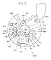
- Fig. 3 shows the integration of the fluidic components 100 into a cartridge 300.
- the cartridge 300 is flat and disc-like and is shown as having a rotational axis 102.
- the fluid reservoir 306 filled with a fluid 307 is sealed with a pierceable seal 308 in this example and there is a piercing element 310 on the wall of the fluid chamber 104.
- the fluid reservoir has a number of engaging surfaces or reservoir opening elements 312 which may be manipulated manually or by an apparatus such as an actuator which causes the pierceable seal 308 to contact the piercing element 310. This then causes the fluid chamber 104 to fill with the fluid 307.
- the fluid chamber 104 is shown as being connected to a first duct 106.
- the first duct 106 is connected to an aliquoting chamber 108.
- centrifugal force forces fluid 307 through the duct 106. This then causes the aliquoting chamber 108 to fill with the fluid 307.
- the aliquoting chamber 108 is shown as being connected to second duct 110 which leads to the metering chamber 112 as is shown in Fig. 1 .
- the aliquoting chamber 108 is laid out in a plane-like fashion aligned with the plane of the disc.
- the rotational axis is perpendicular to the plane.
- Attached to the aliquoting chamber 108 is an excess fluid container 132. This is an optional element.
- the metering chamber 112 is shown as being connected to a downstream fluidic element 122 via a tube 120. There is however a valve 121 located between the metering chamber 112 and the tube 120.
- the downstream fluidic element 122 is part of a fluidic structure 336 for processing a biological sample into a processed biological sample.
- the fluidic structure 336 comprises a number of fluidic elements 338 that are connected by various ducts and siphons 340. There are also a number of vents 342 within the fluidic structure 336. In this example there is an opening 346 which enables a biological sample to be placed into the fluidic structure 336. There is also a cover lid 348 which is used to close and seal the opening 346.
- the fluidic structure 336 also comprises a measurement structure 344 which allows a measurement to be made on the biological sample using a measurement system.
- the measurement system may for instance be an optical, electrical, or a combination of the two system for making the measurement on the processed biological sample.
- the processing of the biological sample can be controlled by controlling the rotational rate about the rotational axis and duration.
- the siphons 340 are designed to be filled automatically using a capillary action. However, a sufficiently large rotational rate about the rotational axis 102 will produce a centrifugal force which will oppose the capillary action.
- the processing of the biological sample can be controlled.
- the biological sample may be placed into the inlet 346 and the rotation rate of the system may be controlled. Then at some point an actuator or other mechanical means is used to manipulate the reservoir opening element and causes the piercing element 310 to pierce the pierceable seal 308. Rotation can then force fluid into the aliquoting chamber and a variety of rotational rates may be used to perform multiple aliquotations using the cartridge 300.
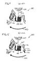
- Figs. 4-10 illustrate how the fluidic components 100 may be used to perform multiple aliquotations of fluid to the downstream fluidic element 122.
- fluid has been added to the fluid chamber 104.
- the cartridge is then spun about the axis of rotation 102. This forces fluid 307 to travel through the first duct 106 into the aliquoting chamber 108.
- the fluid 307 then fills the aliquoting chamber 108 and the corresponding radially outwards portion of the second duct 110 with fluid.
- Fig. 5 shows the cartridge spinning at the same rate and same direction 400 as was shown in Fig. 4 .
- the fluid 307 can be shown as filling the second duct 110 and the aliquoting chamber 108 to the maximum fluid level 500 which is set by the fluid connection entrance 136.
- Excess fluid 307 can be shown as being filled into the excess fluid chamber 132 and the fail safe chamber 140.
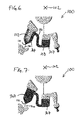
- FIG. 6 the disc stops or slows its rate of rotation.
- Capillary action in the second duct 110 and the metering chamber 112 is shown as beginning to draw fluid into the metering chamber 112.
- the fluid 307 first fills the periphery or edge of the metering chamber 112. This helps preventing the formation or adhesion of bubbles within the metering chamber 112.
- the cartridge is rapidly de-accelerated inertia of the fluid 307 may also help it to enter the metering chamber 112.
- Fig. 7 the cartridge is shown as being still stationary or at a reduced rotation rate and the metering chamber 112 is completely filled with fluid 307.
- the cartridge or disc may still be considered to be at rest.
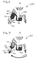
- Fig. 8 shows the same view as is shown in Fig. 7 except a dashed line 800 has been drawn in the metering chamber 112.
- This line 800 in the metering chamber 112 divides the fluid in the metering chamber into several parts or portions.
- a part of the fluid volume or the whole fluid volume 804 radially inward (closer to axis of rotation 102) from the line 800 may flow back into the reservoir.
- the radially outward part (further from the axis of rotation 102) or part 802 may be transferred into the downstream fluidic element 122.
- the radially inward part 804 can be referred to as the remaining part of the fluid and the radially outward part 802 can be referred to as the part of the fluid 802 that is transferred into the downstream fluidic element 122.
- the volume of the fluid 802 is the aliquot.
- the disc begins to accelerate and spin around in the direction 400.
- the disc for instance may spin at the rate shown in Figs. 1 and 2 .
- the disc accelerates; this causes the capillary valve 121 to open.
- the remaining part of the fluid 804 was transferred back to the aliquoting chamber 108.
- the part of the fluid 802 is in the process of being transferred to the downstream fluidic element 122. A drop of the fluid can be seen dropping from the tube 120.
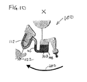
- Fig. 10 it can be seen that the fluid volume 802 has been completely transferred to the downstream fluidic element 122 and is no longer visible in Fig. 10 .
- the remaining part of the fluid 804 has been transferred into the aliquoting chamber 108 and is mixed with the fluid 307.
- the first aliquotation step is finished; the process may be repeated again from Fig. 6 and may be repeated until the fluid volume 307 in the aliquoting chamber 108 is smaller than the volume of the metering chamber 112.
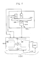
- Fig. 11 shows an example of an automatic analyzer.
- the automatic analyzer 1100 is adapted for receiving a cartridge 300.
- There is a cartridge spinner 1102 which is operable for rotating the cartridge 300 about the rotational axis 102.
- the cartridge spinner 1102 has a motor 1104 attached to a gripper 1106 which attaches to a portion of the cartridge 1108.
- the cartridge 300 is shown further as having a measurement or transparent structure 1110.
- the cartridge 300 can be rotated such that the measurement structure 1110 goes in front of a measurement system 1112 which can perform for example an optical measurement on the processed biological sample.
- the actuator 1104 as was shown previously is also shown in this Fig. It can be used to open a fluid reservoirs in the cartridge 100. In some examples the actuator may be replaced with a dispenser with a dosing needle for filling the fluid chamber of the cartridge 300.
- the actuator 1111, the cartridge spinner 1102, and the measurement system 1112 are shown as all being connected to a hardware interface 1116 of a controller 1114.
- the controller 1114 contains a processor 1118 in communication with the hardware interface 1116, electronic storage 1120, electronic memory 1122, and a network interface 1124.
- the electronic memory 1130 has a machine executable instructions which enables the processor 1118 to control the operation and function of the automatic analyzer 1100.
- the electronic storage 1120 is shown as containing a measurement 1132 that was acquired when instructions 1130 were executed by the processor 1118.
- the network interface 1124 enables the processor 1118 to send the measurement 1132 via network interface 1126 to a laboratory information system 1128.
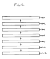
- Fig. 12 shows a flowchart which illustrates a method of operating the automatic analyzer 1100 of Fig. 11 .
- the commands 1130 cause the processor 1118 to control the cartridge spinner to control the rotation rate of the cartridge to process the biological sample into a processed biological sample using the fluidic structure.
- the commands 1130 cause the processor 1118 to control the cartridge spinner 1102 to control the rotation rate of the cartridge to transport the fluid from the fluid chamber to the aliquoting chamber via the first duct.
- the instructions 1130 cause the processor 1118 to control the cartridge spinner to force fluid in the reservoir to flow into the second duct and to fill the metering chamber a first time.
- step 1106 execution of the instructions 1130 cause the processor 1118 to control the cartridge spinner 1102 to increase the rotational rate of the cartridge to transfer a first part of the fluid from the metering chamber through the valve and to transfer a first remaining part back into the aliquoting chamber.
- step 1208 execution of the instructions 1130 cause the processor 1118 to control the cartridge spinner 1102 to decrease the rotational rate of the cartridge to force fluid in the reservoir to flow into the second duct and to fill the metering chamber a second time.
- step 1210 execution of the instructions 1130 cause the processor to control the cartridge spinner to increase the rotational rate of the cartridge to transfer a second part of the fluid from the metering chamber through the valve and to transfer a second remaining part of the fluid back into the aliquoting chamber.
- step 1212 execution of the instructions 1130 cause the processor 1118 to control the measurement system 1112 to perform the measurement using the measurement structure.
Landscapes
- Chemical & Material Sciences (AREA)
- Health & Medical Sciences (AREA)
- General Health & Medical Sciences (AREA)
- Analytical Chemistry (AREA)
- Life Sciences & Earth Sciences (AREA)
- Physics & Mathematics (AREA)
- Biochemistry (AREA)
- General Physics & Mathematics (AREA)
- Immunology (AREA)
- Pathology (AREA)
- Hematology (AREA)
- Clinical Laboratory Science (AREA)
- Chemical Kinetics & Catalysis (AREA)
- Dispersion Chemistry (AREA)
- Automatic Analysis And Handling Materials Therefor (AREA)
Priority Applications (9)
| Application Number | Priority Date | Filing Date | Title |
|---|---|---|---|
| EP14171424.6A EP2952257A1 (de) | 2014-06-06 | 2014-06-06 | Drehbare Patrone zur Verarbeitung und Analyse einer biologischen Probe |
| JP2016562796A JP6604966B2 (ja) | 2014-06-06 | 2015-06-03 | 生体試料を処理および分析するための回転可能カートリッジ |
| EP15725384.0A EP3151962B1 (de) | 2014-06-06 | 2015-06-03 | Drehbare patrone zur verarbeitung und analyse einer biologischen probe |
| PCT/EP2015/062337 WO2015185600A1 (en) | 2014-06-06 | 2015-06-03 | Rotatable cartridge for processing and analyzing a biological sample |
| CN201580025717.4A CN106660040B (zh) | 2014-06-06 | 2015-06-03 | 用于处理和分析生物样品的可旋转盒 |
| KR1020167031818A KR101930611B1 (ko) | 2014-06-06 | 2015-06-03 | 생물학적 샘플을 처리 및 분석하기 위한 회전가능한 카트리지 |
| US15/352,672 US9962699B2 (en) | 2014-06-06 | 2016-11-16 | Rotatable cartridge for processing and analyzing a biological sample |
| US15/943,093 US10478817B2 (en) | 2014-06-06 | 2018-04-02 | Rotatable cartridge for processing and analyzing a biological sample |
| US16/599,673 US11406979B2 (en) | 2014-06-06 | 2019-10-11 | Rotatable cartridge for processing and analyzing a biological sample and dispensing method therewith |
Applications Claiming Priority (1)
| Application Number | Priority Date | Filing Date | Title |
|---|---|---|---|
| EP14171424.6A EP2952257A1 (de) | 2014-06-06 | 2014-06-06 | Drehbare Patrone zur Verarbeitung und Analyse einer biologischen Probe |
Publications (1)
| Publication Number | Publication Date |
|---|---|
| EP2952257A1 true EP2952257A1 (de) | 2015-12-09 |
Family
ID=50884290
Family Applications (2)
| Application Number | Title | Priority Date | Filing Date |
|---|---|---|---|
| EP14171424.6A Withdrawn EP2952257A1 (de) | 2014-06-06 | 2014-06-06 | Drehbare Patrone zur Verarbeitung und Analyse einer biologischen Probe |
| EP15725384.0A Active EP3151962B1 (de) | 2014-06-06 | 2015-06-03 | Drehbare patrone zur verarbeitung und analyse einer biologischen probe |
Family Applications After (1)
| Application Number | Title | Priority Date | Filing Date |
|---|---|---|---|
| EP15725384.0A Active EP3151962B1 (de) | 2014-06-06 | 2015-06-03 | Drehbare patrone zur verarbeitung und analyse einer biologischen probe |
Country Status (6)
| Country | Link |
|---|---|
| US (3) | US9962699B2 (de) |
| EP (2) | EP2952257A1 (de) |
| JP (1) | JP6604966B2 (de) |
| KR (1) | KR101930611B1 (de) |
| CN (1) | CN106660040B (de) |
| WO (1) | WO2015185600A1 (de) |
Families Citing this family (13)
| Publication number | Priority date | Publication date | Assignee | Title |
|---|---|---|---|---|
| DE102012202775B4 (de) * | 2012-02-23 | 2016-08-25 | Hahn-Schickard-Gesellschaft für angewandte Forschung e.V. | Fluidikmodul, vorrichtung und verfahren zum pumpen einer flüssigkeit |
| CN110579435B (zh) | 2012-10-15 | 2023-09-26 | 纳诺赛莱克特生物医药股份有限公司 | 颗粒分选的系统、设备和方法 |
| EP2952258A1 (de) * | 2014-06-06 | 2015-12-09 | Roche Diagnostics GmbH | Drehbare Kartusche zur Analyse einer biologischen Probe |
| EP3151963B1 (de) | 2014-06-06 | 2018-03-14 | Roche Diagnostics GmbH | Drehbare kartusche mit dosierkammer zur analyse einer biologischen probe |
| EP2952257A1 (de) * | 2014-06-06 | 2015-12-09 | Roche Diagnostics GmbH | Drehbare Patrone zur Verarbeitung und Analyse einer biologischen Probe |
| EP2957890A1 (de) * | 2014-06-16 | 2015-12-23 | Roche Diagnostics GmbH | Patrone mit drehbarem Deckel |
| CN109211860B (zh) * | 2018-09-29 | 2023-11-17 | 厦门大学 | 一种多项式检测光盘和检测方法 |
| WO2020142845A1 (en) | 2019-01-11 | 2020-07-16 | Fredsense Technologies Corp. | Systems and methods for voltammetric detection |
| IT202000004015A1 (it) * | 2020-02-26 | 2021-08-26 | St Ortopedico Rizzoli | Sistema di allenamento per l'alimentazione di un fluido in una microcamera di un dispositivo microfluidico |
| WO2022025044A1 (ja) * | 2020-07-29 | 2022-02-03 | 京セラ株式会社 | 流路デバイス |
| CN115155678B (zh) * | 2022-06-09 | 2024-02-09 | 安图实验仪器(郑州)有限公司 | 一种离心式微流控分析芯片 |
| CN116713048A (zh) * | 2023-07-25 | 2023-09-08 | 石家庄禾柏生物技术股份有限公司 | 一种液体定量转移结构 |
| LU504853B1 (de) * | 2023-08-03 | 2025-02-03 | Dermagnostix GmbH | Probenträger zum Verwenden in einem rotationsbasierten Verfahren zur Vervielfältigung von DNA und/oder Bestimmung von Nukleinsäuren |
Citations (5)
| Publication number | Priority date | Publication date | Assignee | Title |
|---|---|---|---|---|
| EP2096444A1 (de) * | 2006-10-31 | 2009-09-02 | Panasonic Corporation | Mikrochip und analysegerät unter verwendung davon |
| US20090246082A1 (en) * | 2008-03-28 | 2009-10-01 | Hiroshi Saiki | Analysis device and an analysis apparatus using the analysis device |
| EP2302396A1 (de) * | 2008-07-17 | 2011-03-30 | Panasonic Corporation | Analysegerät und analyseverfahren unter verwendung des analysegerätes |
| US8114351B2 (en) | 2007-11-24 | 2012-02-14 | Roche Diagnostics Operations, Inc. | Analysis system and method for the analysis of a body fluid sample for an analyte contained therein |
| US8470588B2 (en) | 2006-09-27 | 2013-06-25 | Roche Diagnostics Operations, Inc. | Rotatable test element |
Family Cites Families (49)
| Publication number | Priority date | Publication date | Assignee | Title |
|---|---|---|---|---|
| US3864089A (en) | 1973-12-10 | 1975-02-04 | Atomic Energy Commission | Multiple-sample rotor assembly for blood fraction preparation |
| US4284602A (en) | 1979-12-10 | 1981-08-18 | Immutron, Inc. | Integrated fluid manipulator |
| FR2503866A1 (fr) * | 1981-04-14 | 1982-10-15 | Guigan Jean | Dispositif pour delivrer une dose determinee d'un echantillon de liquide dans une cellule et procede associe |
| US5089417A (en) * | 1987-07-01 | 1992-02-18 | Miles Inc. | Fluid separation and processing device |
| US5173262A (en) | 1987-07-17 | 1992-12-22 | Martin Marietta Energy Systems, Inc. | Rotor assembly and method for automatically processing liquids |
| US5160702A (en) * | 1989-01-17 | 1992-11-03 | Molecular Devices Corporation | Analyzer with improved rotor structure |
| US5061381A (en) | 1990-06-04 | 1991-10-29 | Abaxis, Inc. | Apparatus and method for separating cells from biological fluids |
| US5173193A (en) | 1991-04-01 | 1992-12-22 | Schembri Carol T | Centrifugal rotor having flow partition |
| US5186844A (en) | 1991-04-01 | 1993-02-16 | Abaxis, Inc. | Apparatus and method for continuous centrifugal blood cell separation |
| US5304348A (en) | 1992-02-11 | 1994-04-19 | Abaxis, Inc. | Reagent container for analytical rotor |
| US5591643A (en) | 1993-09-01 | 1997-01-07 | Abaxis, Inc. | Simplified inlet channels |
| US6299839B1 (en) * | 1995-08-31 | 2001-10-09 | First Medical, Inc. | System and methods for performing rotor assays |
| WO2001087487A2 (en) * | 2000-05-15 | 2001-11-22 | Tecan Trading Ag | Bidirectional flow centrifugal microfluidic devices |
| US7189368B2 (en) * | 2001-09-17 | 2007-03-13 | Gyros Patent Ab | Functional unit enabling controlled flow in a microfluidic device |
| US7138091B2 (en) * | 2003-07-18 | 2006-11-21 | Dade Behring Inc. | Reaction cuvette having anti-wicking features for use in an automatic clinical analyzer |
| CN2632680Y (zh) * | 2003-07-29 | 2004-08-11 | 深圳迈瑞生物医疗电子股份有限公司 | 用于全自动生化分析仪的试剂瓶安装座 |
| EP1669733B1 (de) * | 2003-10-03 | 2019-01-16 | National Institute for Materials Science | Testchip |
| DE102004046396A1 (de) | 2004-09-24 | 2006-04-13 | Land Baden-Württemberg, vertreten durch das Ministerium für Wissenschaft, Forschung und Kunst Baden-Württemberg, vertreten durch den Minister | Partikelsedimentationsvorrichtung und Verfahren zum Durchführen einer Partikelsedimentation |
| JP4361879B2 (ja) * | 2005-01-07 | 2009-11-11 | 株式会社日立ハイテクノロジーズ | 化学分析装置及び化学分析カートリッジ |
| JP4660662B2 (ja) * | 2005-09-06 | 2011-03-30 | アークレイ株式会社 | カートリッジ |
| US20090123337A1 (en) | 2005-06-24 | 2009-05-14 | Arkray,Inc | Cartridge |
| JPWO2007116909A1 (ja) | 2006-04-04 | 2009-08-20 | パナソニック株式会社 | 試料液分析用パネル |
| KR101335920B1 (ko) | 2006-08-02 | 2013-12-03 | 삼성전자주식회사 | 박막화학분석장치 및 이를 이용한 분석방법 |
| EP1939629A3 (de) | 2006-08-11 | 2011-03-09 | Samsung Electronics Co., Ltd. | Vorrichtung zur zentrifugalkraftbasierten Magnetpositionssteuerung sowie scheibenförmiges Mikrofluidiksystem |
| US8273310B2 (en) * | 2006-09-05 | 2012-09-25 | Samsung Electronics Co., Ltd. | Centrifugal force-based microfluidic device for nucleic acid extraction and microfluidic system including the microfluidic device |
| US7951333B2 (en) * | 2006-09-05 | 2011-05-31 | Samsung Electronics Co., Ltd. | Centrifugal force-based microfluidic device for protein detection and microfluidic system including the same |
| KR100818274B1 (ko) * | 2006-09-05 | 2008-04-01 | 삼성전자주식회사 | 미세유동 시스템 제어장치 및 그 방법, 및 미세유동 시스템 |
| JP4880419B2 (ja) | 2006-10-18 | 2012-02-22 | ローム株式会社 | 計量部を有するチップおよびこれを用いた液体試料の計量方法 |
| KR101305976B1 (ko) * | 2007-02-12 | 2013-09-12 | 삼성전자주식회사 | 연속희석을 위한 원심력 기반의 미세유동장치 및 이를포함하는 미세유동시스템 |
| KR100858091B1 (ko) | 2007-04-24 | 2008-09-10 | 삼성전자주식회사 | 시료 분배 구조를 갖는 원심력 기반의 미세유동장치 및이를 포함하는 미세유동시스템 |
| KR101335727B1 (ko) * | 2007-08-22 | 2013-12-04 | 삼성전자주식회사 | 원심력 기반의 혈액 검사용 디스크형 미세유동장치 |
| EP2072131B1 (de) | 2007-12-13 | 2015-04-22 | Roche Diagnostics GmbH | Mikrofluidisches Element zur Durchmischung einer Flüssigkeit in einer Reagenz |
| US7938030B2 (en) * | 2008-02-06 | 2011-05-10 | Panasonic Corporation | Analytical device |
| KR101157177B1 (ko) * | 2008-11-27 | 2012-06-20 | 삼성전자주식회사 | 표적 물질 처리 시스템 및 방법 |
| GB2466644B (en) | 2008-12-30 | 2011-05-11 | Biosurfit Sa | Liquid handling |
| TWI360438B (en) * | 2009-08-25 | 2012-03-21 | Ind Tech Res Inst | Analytical system, analytical method and flow-path |
| EP2309266A1 (de) | 2009-09-21 | 2011-04-13 | F. Hoffmann-La Roche AG | Verfahren zur Durchführung von Reaktionen in einer Analysevorrichtung |
| EP2329877A1 (de) | 2009-12-04 | 2011-06-08 | Roche Diagnostics GmbH | Mikrofluidisches Element zur Analyse einer Flüssigkeitsprobe |
| KR101722548B1 (ko) * | 2010-01-29 | 2017-04-03 | 삼성전자주식회사 | 원심력기반의 미세유동장치 및 이를 이용한 유체시료 내 분석대상물질 검출방법 |
| EP2486978A1 (de) | 2010-10-28 | 2012-08-15 | Roche Diagnostics GmbH | Mikrofluidischer Testträger zum Aufteilen einer Flüssigkeitsmenge in Teilmengen |
| EP2455162A1 (de) | 2010-10-29 | 2012-05-23 | Roche Diagnostics GmbH | Mikrofluidisches Element zur Analyse einer Probenflüssigkeit |
| KR101252259B1 (ko) * | 2011-12-12 | 2013-04-08 | 포항공과대학교 산학협력단 | 디스크형 미세 유체 시스템 및 혈액 상태 확인 방법 |
| DE102012202775B4 (de) * | 2012-02-23 | 2016-08-25 | Hahn-Schickard-Gesellschaft für angewandte Forschung e.V. | Fluidikmodul, vorrichtung und verfahren zum pumpen einer flüssigkeit |
| CN103424304B (zh) | 2012-05-18 | 2015-08-26 | 光宝科技股份有限公司 | 分析卡匣 |
| EP3135377A1 (de) * | 2013-04-15 | 2017-03-01 | Becton, Dickinson and Company | Entnahmevorrichtung für biologische flüssigkeit sowie trennungs- und testsystem für biologischen flüssigkeiten |
| EP2952257A1 (de) * | 2014-06-06 | 2015-12-09 | Roche Diagnostics GmbH | Drehbare Patrone zur Verarbeitung und Analyse einer biologischen Probe |
| EP2952258A1 (de) | 2014-06-06 | 2015-12-09 | Roche Diagnostics GmbH | Drehbare Kartusche zur Analyse einer biologischen Probe |
| EP3151963B1 (de) * | 2014-06-06 | 2018-03-14 | Roche Diagnostics GmbH | Drehbare kartusche mit dosierkammer zur analyse einer biologischen probe |
| EP2957890A1 (de) | 2014-06-16 | 2015-12-23 | Roche Diagnostics GmbH | Patrone mit drehbarem Deckel |
-
2014
- 2014-06-06 EP EP14171424.6A patent/EP2952257A1/de not_active Withdrawn
-
2015
- 2015-06-03 EP EP15725384.0A patent/EP3151962B1/de active Active
- 2015-06-03 KR KR1020167031818A patent/KR101930611B1/ko not_active Expired - Fee Related
- 2015-06-03 WO PCT/EP2015/062337 patent/WO2015185600A1/en not_active Ceased
- 2015-06-03 CN CN201580025717.4A patent/CN106660040B/zh active Active
- 2015-06-03 JP JP2016562796A patent/JP6604966B2/ja active Active
-
2016
- 2016-11-16 US US15/352,672 patent/US9962699B2/en active Active
-
2018
- 2018-04-02 US US15/943,093 patent/US10478817B2/en not_active Expired - Fee Related
-
2019
- 2019-10-11 US US16/599,673 patent/US11406979B2/en active Active
Patent Citations (5)
| Publication number | Priority date | Publication date | Assignee | Title |
|---|---|---|---|---|
| US8470588B2 (en) | 2006-09-27 | 2013-06-25 | Roche Diagnostics Operations, Inc. | Rotatable test element |
| EP2096444A1 (de) * | 2006-10-31 | 2009-09-02 | Panasonic Corporation | Mikrochip und analysegerät unter verwendung davon |
| US8114351B2 (en) | 2007-11-24 | 2012-02-14 | Roche Diagnostics Operations, Inc. | Analysis system and method for the analysis of a body fluid sample for an analyte contained therein |
| US20090246082A1 (en) * | 2008-03-28 | 2009-10-01 | Hiroshi Saiki | Analysis device and an analysis apparatus using the analysis device |
| EP2302396A1 (de) * | 2008-07-17 | 2011-03-30 | Panasonic Corporation | Analysegerät und analyseverfahren unter verwendung des analysegerätes |
Non-Patent Citations (3)
| Title |
|---|
| KIM, TAE-HYEONG ET AL.: "Flow-enhanced electrochemical immunosensors on centrifugal microfluidic platforms", LAB ON A CHIP 13.18, 2013, pages 3747 - 3754 |
| MARTINEZ-DUARTE, RODRIGO ET AL.: "The integration of 3D carbon-electrode dielectrophoresis on a CD-like centrifugal microfluidic platform", LAB ON A CHIP 10.8, 2010, pages 1030 - 1043 |
| PARK ET AL.: "Multifunctional Microvalves Control by Optical Illumination on Nanoheaters and Its Application in Centrifugal Microfluidic Devices", LAB CHIP, vol. 7, 2007, pages 557 - 564, XP007902269, DOI: doi:10.1039/b616112j |
Also Published As
| Publication number | Publication date |
|---|---|
| US20200038858A1 (en) | 2020-02-06 |
| JP2017516986A (ja) | 2017-06-22 |
| US20180221872A1 (en) | 2018-08-09 |
| CN106660040B (zh) | 2019-08-16 |
| US9962699B2 (en) | 2018-05-08 |
| US20170095811A1 (en) | 2017-04-06 |
| EP3151962A1 (de) | 2017-04-12 |
| US10478817B2 (en) | 2019-11-19 |
| JP6604966B2 (ja) | 2019-11-13 |
| WO2015185600A1 (en) | 2015-12-10 |
| KR101930611B1 (ko) | 2018-12-18 |
| KR20160144488A (ko) | 2016-12-16 |
| US11406979B2 (en) | 2022-08-09 |
| EP3151962B1 (de) | 2019-08-07 |
| CN106660040A (zh) | 2017-05-10 |
Similar Documents
| Publication | Publication Date | Title |
|---|---|---|
| US11406979B2 (en) | Rotatable cartridge for processing and analyzing a biological sample and dispensing method therewith | |
| US10307757B2 (en) | Rotatable cartridge with a metering chamber for analyzing a biological sample | |
| US10016758B2 (en) | Rotatable cartridge for analyzing a biological sample | |
| US9808801B2 (en) | Rotatable cartridge for measuring a property of a biological sample | |
| EP3380236B1 (de) | Bestimmung der menge eines analyts in einer blutprobe |
Legal Events
| Date | Code | Title | Description |
|---|---|---|---|
| PUAI | Public reference made under article 153(3) epc to a published international application that has entered the european phase |
Free format text: ORIGINAL CODE: 0009012 |
|
| AK | Designated contracting states |
Kind code of ref document: A1 Designated state(s): AL AT BE BG CH CY CZ DE DK EE ES FI FR GB GR HR HU IE IS IT LI LT LU LV MC MK MT NL NO PL PT RO RS SE SI SK SM TR |
|
| AX | Request for extension of the european patent |
Extension state: BA ME |
|
| STAA | Information on the status of an ep patent application or granted ep patent |
Free format text: STATUS: THE APPLICATION IS DEEMED TO BE WITHDRAWN |
|
| 18D | Application deemed to be withdrawn |
Effective date: 20160610 |