EP2952247B1 - Method for using ceramic filter, and filter device - Google Patents
Method for using ceramic filter, and filter device Download PDFInfo
- Publication number
- EP2952247B1 EP2952247B1 EP14745945.7A EP14745945A EP2952247B1 EP 2952247 B1 EP2952247 B1 EP 2952247B1 EP 14745945 A EP14745945 A EP 14745945A EP 2952247 B1 EP2952247 B1 EP 2952247B1
- Authority
- EP
- European Patent Office
- Prior art keywords
- face
- ceramic filter
- mixed fluid
- path
- filter
- Prior art date
- Legal status (The legal status is an assumption and is not a legal conclusion. Google has not performed a legal analysis and makes no representation as to the accuracy of the status listed.)
- Not-in-force
Links
- 239000000919 ceramic Substances 0.000 title claims description 110
- 238000000034 method Methods 0.000 title claims description 52
- 239000012530 fluid Substances 0.000 claims description 153
- 239000012528 membrane Substances 0.000 claims description 62
- 238000000926 separation method Methods 0.000 claims description 56
- XLYOFNOQVPJJNP-UHFFFAOYSA-N water Substances O XLYOFNOQVPJJNP-UHFFFAOYSA-N 0.000 claims description 53
- 238000010438 heat treatment Methods 0.000 claims description 25
- 239000000126 substance Substances 0.000 claims description 23
- 239000007788 liquid Substances 0.000 claims description 19
- LFQSCWFLJHTTHZ-UHFFFAOYSA-N Ethanol Chemical compound CCO LFQSCWFLJHTTHZ-UHFFFAOYSA-N 0.000 claims description 16
- VYPSYNLAJGMNEJ-UHFFFAOYSA-N Silicium dioxide Chemical compound O=[Si]=O VYPSYNLAJGMNEJ-UHFFFAOYSA-N 0.000 claims description 12
- 230000008569 process Effects 0.000 claims description 10
- 125000000524 functional group Chemical group 0.000 claims description 7
- 239000000377 silicon dioxide Substances 0.000 claims description 6
- 239000012466 permeate Substances 0.000 claims description 4
- 230000000149 penetrating effect Effects 0.000 claims description 3
- 230000000881 depressing effect Effects 0.000 claims 1
- 238000001914 filtration Methods 0.000 description 18
- 230000010287 polarization Effects 0.000 description 13
- 238000009834 vaporization Methods 0.000 description 10
- 230000008016 vaporization Effects 0.000 description 10
- 239000004020 conductor Substances 0.000 description 9
- 239000000463 material Substances 0.000 description 9
- 230000035515 penetration Effects 0.000 description 9
- 238000001612 separation test Methods 0.000 description 7
- 230000000052 comparative effect Effects 0.000 description 6
- 230000007423 decrease Effects 0.000 description 6
- 230000006837 decompression Effects 0.000 description 4
- 238000003756 stirring Methods 0.000 description 4
- 229910052782 aluminium Inorganic materials 0.000 description 3
- XAGFODPZIPBFFR-UHFFFAOYSA-N aluminium Chemical compound [Al] XAGFODPZIPBFFR-UHFFFAOYSA-N 0.000 description 3
- 230000007797 corrosion Effects 0.000 description 3
- 238000005260 corrosion Methods 0.000 description 3
- 230000000694 effects Effects 0.000 description 3
- 230000004907 flux Effects 0.000 description 3
- 239000011521 glass Substances 0.000 description 3
- 239000000203 mixture Substances 0.000 description 3
- 238000012856 packing Methods 0.000 description 3
- 239000011148 porous material Substances 0.000 description 3
- 230000009467 reduction Effects 0.000 description 3
- IJGRMHOSHXDMSA-UHFFFAOYSA-N Atomic nitrogen Chemical compound N#N IJGRMHOSHXDMSA-UHFFFAOYSA-N 0.000 description 2
- OKTJSMMVPCPJKN-UHFFFAOYSA-N Carbon Chemical compound [C] OKTJSMMVPCPJKN-UHFFFAOYSA-N 0.000 description 2
- CURLTUGMZLYLDI-UHFFFAOYSA-N Carbon dioxide Chemical compound O=C=O CURLTUGMZLYLDI-UHFFFAOYSA-N 0.000 description 2
- 229920001875 Ebonite Polymers 0.000 description 2
- XEEYBQQBJWHFJM-UHFFFAOYSA-N Iron Chemical compound [Fe] XEEYBQQBJWHFJM-UHFFFAOYSA-N 0.000 description 2
- CTQNGGLPUBDAKN-UHFFFAOYSA-N O-Xylene Chemical group CC1=CC=CC=C1C CTQNGGLPUBDAKN-UHFFFAOYSA-N 0.000 description 2
- 229910052799 carbon Inorganic materials 0.000 description 2
- 230000002542 deteriorative effect Effects 0.000 description 2
- 239000007789 gas Substances 0.000 description 2
- 238000003754 machining Methods 0.000 description 2
- 230000007246 mechanism Effects 0.000 description 2
- VNWKTOKETHGBQD-UHFFFAOYSA-N methane Chemical compound C VNWKTOKETHGBQD-UHFFFAOYSA-N 0.000 description 2
- 229920002379 silicone rubber Polymers 0.000 description 2
- 239000004945 silicone rubber Substances 0.000 description 2
- VZSRBBMJRBPUNF-UHFFFAOYSA-N 2-(2,3-dihydro-1H-inden-2-ylamino)-N-[3-oxo-3-(2,4,6,7-tetrahydrotriazolo[4,5-c]pyridin-5-yl)propyl]pyrimidine-5-carboxamide Chemical compound C1C(CC2=CC=CC=C12)NC1=NC=C(C=N1)C(=O)NCCC(N1CC2=C(CC1)NN=N2)=O VZSRBBMJRBPUNF-UHFFFAOYSA-N 0.000 description 1
- WZFUQSJFWNHZHM-UHFFFAOYSA-N 2-[4-[2-(2,3-dihydro-1H-inden-2-ylamino)pyrimidin-5-yl]piperazin-1-yl]-1-(2,4,6,7-tetrahydrotriazolo[4,5-c]pyridin-5-yl)ethanone Chemical compound C1C(CC2=CC=CC=C12)NC1=NC=C(C=N1)N1CCN(CC1)CC(=O)N1CC2=C(CC1)NN=N2 WZFUQSJFWNHZHM-UHFFFAOYSA-N 0.000 description 1
- JQMFQLVAJGZSQS-UHFFFAOYSA-N 2-[4-[2-(2,3-dihydro-1H-inden-2-ylamino)pyrimidin-5-yl]piperazin-1-yl]-N-(2-oxo-3H-1,3-benzoxazol-6-yl)acetamide Chemical compound C1C(CC2=CC=CC=C12)NC1=NC=C(C=N1)N1CCN(CC1)CC(=O)NC1=CC2=C(NC(O2)=O)C=C1 JQMFQLVAJGZSQS-UHFFFAOYSA-N 0.000 description 1
- 241000196324 Embryophyta Species 0.000 description 1
- 235000006508 Nelumbo nucifera Nutrition 0.000 description 1
- 240000002853 Nelumbo nucifera Species 0.000 description 1
- 229910021536 Zeolite Inorganic materials 0.000 description 1
- 230000002411 adverse Effects 0.000 description 1
- 125000000217 alkyl group Chemical group 0.000 description 1
- PNEYBMLMFCGWSK-UHFFFAOYSA-N aluminium oxide Inorganic materials [O-2].[O-2].[O-2].[Al+3].[Al+3] PNEYBMLMFCGWSK-UHFFFAOYSA-N 0.000 description 1
- 125000003118 aryl group Chemical group 0.000 description 1
- 125000004432 carbon atom Chemical group C* 0.000 description 1
- 229910002092 carbon dioxide Inorganic materials 0.000 description 1
- 239000001569 carbon dioxide Substances 0.000 description 1
- 230000008859 change Effects 0.000 description 1
- 238000007796 conventional method Methods 0.000 description 1
- 230000003247 decreasing effect Effects 0.000 description 1
- 230000006866 deterioration Effects 0.000 description 1
- HNPSIPDUKPIQMN-UHFFFAOYSA-N dioxosilane;oxo(oxoalumanyloxy)alumane Chemical compound O=[Si]=O.O=[Al]O[Al]=O HNPSIPDUKPIQMN-UHFFFAOYSA-N 0.000 description 1
- 239000003814 drug Substances 0.000 description 1
- 235000013305 food Nutrition 0.000 description 1
- 239000001257 hydrogen Substances 0.000 description 1
- 229910052739 hydrogen Inorganic materials 0.000 description 1
- 125000004435 hydrogen atom Chemical class [H]* 0.000 description 1
- 230000006872 improvement Effects 0.000 description 1
- 238000009434 installation Methods 0.000 description 1
- 239000011810 insulating material Substances 0.000 description 1
- 229910052742 iron Inorganic materials 0.000 description 1
- 229910052751 metal Inorganic materials 0.000 description 1
- 239000002184 metal Substances 0.000 description 1
- 238000002156 mixing Methods 0.000 description 1
- 230000004048 modification Effects 0.000 description 1
- 238000012986 modification Methods 0.000 description 1
- 239000003345 natural gas Substances 0.000 description 1
- 229910052757 nitrogen Inorganic materials 0.000 description 1
- TVMXDCGIABBOFY-UHFFFAOYSA-N octane Chemical compound CCCCCCCC TVMXDCGIABBOFY-UHFFFAOYSA-N 0.000 description 1
- 125000002347 octyl group Chemical group [H]C([*])([H])C([H])([H])C([H])([H])C([H])([H])C([H])([H])C([H])([H])C([H])([H])C([H])([H])[H] 0.000 description 1
- 229920000620 organic polymer Polymers 0.000 description 1
- 239000002245 particle Substances 0.000 description 1
- 230000002093 peripheral effect Effects 0.000 description 1
- 125000001997 phenyl group Chemical group [H]C1=C([H])C([H])=C(*)C([H])=C1[H] 0.000 description 1
- 238000011084 recovery Methods 0.000 description 1
- 238000007789 sealing Methods 0.000 description 1
- 229910001220 stainless steel Inorganic materials 0.000 description 1
- 239000010935 stainless steel Substances 0.000 description 1
- -1 steam Substances 0.000 description 1
- 238000012360 testing method Methods 0.000 description 1
- 125000003944 tolyl group Chemical group 0.000 description 1
- 239000010457 zeolite Substances 0.000 description 1
Images


Classifications
-
- B—PERFORMING OPERATIONS; TRANSPORTING
- B01—PHYSICAL OR CHEMICAL PROCESSES OR APPARATUS IN GENERAL
- B01D—SEPARATION
- B01D63/00—Apparatus in general for separation processes using semi-permeable membranes
-
- B—PERFORMING OPERATIONS; TRANSPORTING
- B01—PHYSICAL OR CHEMICAL PROCESSES OR APPARATUS IN GENERAL
- B01D—SEPARATION
- B01D63/00—Apparatus in general for separation processes using semi-permeable membranes
- B01D63/06—Tubular membrane modules
- B01D63/066—Tubular membrane modules with a porous block having membrane coated passages
-
- B—PERFORMING OPERATIONS; TRANSPORTING
- B01—PHYSICAL OR CHEMICAL PROCESSES OR APPARATUS IN GENERAL
- B01D—SEPARATION
- B01D61/00—Processes of separation using semi-permeable membranes, e.g. dialysis, osmosis or ultrafiltration; Apparatus, accessories or auxiliary operations specially adapted therefor
- B01D61/36—Pervaporation; Membrane distillation; Liquid permeation
- B01D61/366—Apparatus therefor
-
- B—PERFORMING OPERATIONS; TRANSPORTING
- B01—PHYSICAL OR CHEMICAL PROCESSES OR APPARATUS IN GENERAL
- B01D—SEPARATION
- B01D2311/00—Details relating to membrane separation process operations and control
- B01D2311/26—Further operations combined with membrane separation processes
- B01D2311/2673—Evaporation
-
- B—PERFORMING OPERATIONS; TRANSPORTING
- B01—PHYSICAL OR CHEMICAL PROCESSES OR APPARATUS IN GENERAL
- B01D—SEPARATION
- B01D2313/00—Details relating to membrane modules or apparatus
- B01D2313/04—Specific sealing means
-
- B—PERFORMING OPERATIONS; TRANSPORTING
- B01—PHYSICAL OR CHEMICAL PROCESSES OR APPARATUS IN GENERAL
- B01D—SEPARATION
- B01D2313/00—Details relating to membrane modules or apparatus
- B01D2313/08—Flow guidance means within the module or the apparatus
Definitions
- the present invention relates to a method for using a ceramic filter, and a filter device including a ceramic filter.
- a filter made of ceramic has been used to selectively separate and recover an only specific component from a mixture of multiple components.
- the filter made of ceramic is excellent in mechanical strength, durability, corrosion resistance and the like as compared with a filter made of organic polymer, and hence, the filter is preferably applied as a separation membrane which separates a liquid or gas mixture at a molecule level in a broad field such as a petrochemistry field, a natural gas plant, or a medicine or food field.
- a filter made of ceramic for the purpose of improving a permeation performance while acquiring a separation performance, it is necessary to enlarge an effective membrane area (the area of the separation membrane which comes in contact with a fluid to be treated), and for this necessity, a filter shape is desirably of a monolith type (or a honeycomb type).
- the monolith type of filter has advantages that the filter is hard to bend, is easy to seal, can be made compact and can achieve cost reduction, and the like, as compared with a tube type of filter.
- the monolith type of filter includes a porous supporter having a round pillar-like outer shape and having therein a large number of parallel through channels (also referred to as cells) formed in an axial direction of the filter, and further, a separation membrane having smaller pore diameters than those of the porous supporter is formed on an inner wall surface in which the cells are to be formed.
- Patent Document 1 An example of a prior document in which the conventional monolith type (or honeycomb type) of ceramic filter is disclosed is Patent Document 1.
- Patent Document 2 An example of a prior document in which a fluid separating method using such a filter is disclosed is Patent Document 2.
- a filter (a membrane container) in which a flow speed of the fluid flowing through the filter is increased to improve the separation performance (e.g., see Patent Document 3).
- WO 2004/091756 A1 discloses a ceramic filter where a plurality of through channels is present in a pillar-shaped body extending from a first end face to a second end face. Open ends of both the end faces of the through channels are opened, but in part of the through channels, the open ends of both the end faces are plugged by plugging members.
- main causes for the polarization are (1) a difference between an inner temperature and an outer temperature of the fluid flowing through the cells (a difference in temperature between a central portion and the vicinity of a separation membrane) due to vaporization heat of a permeable substance which has permeated the separation membrane, and (2) a difference between an inner concentration and an outer concentration (a difference in concentration between the central portion and the vicinity of the separation membrane) in "the concentration of the permeable substance" in the fluid flowing through the cells due to permeation of the permeable substance through the separation membrane. That is, when the flow speed lowers, the temperature and the concentration locally lower in a contact interface, and hence, a filter cannot exert any intrinsic performance.
- D is an inner diameter of each cell
- u is an average flow speed
- ⁇ is a density of the fluid
- ⁇ is a viscosity of the fluid.
- the mixed fluid to be treated is allowed to flow only in one direction from an inflow side end face to an outflow side end face of a filter, and is filtered.
- a fluid of the high flow rate corresponding to the sectional area of the filter as described above is filtered, temperature drop of the fluid in a filtering process easily occurs. Therefore, it is necessary to beforehand sufficiently apply heat to the fluid to be treated, but there have been incurred the problems such as installation of a large heater and increase of energy or cost required for an operation of the heater.
- a flow path of the fluid is returned in the membrane container with the intension of increasing the flow speed of the fluid to be treated. Further, the separation performance is intended to be improved in this way.
- a round returning portion for use in returning the fluid is disposed in an end face of a membrane container main body. In consequence, a portion of the membrane container end face in which the returning portion is disposed cannot come in contact with a membrane due to the flowing fluid, which has raised the problem that a treatment amount of the fluid (an effective membrane area) becomes smaller.
- An object of the present invention is to provide a method for using a ceramic filter and a filter device in which a high separation performance is realized while maintaining a high treatment amount.
- the present inventors have divided through channels of a ceramic filter into an outward path and a return path by through channel division means, allowing a mixed fluid to reciprocate through the same filter once or more, and have disposed the through channel division means on plugging portions of water collecting slits. Further, the present inventors have found that the above problem can thus be solved. That is, according to the present invention, the following method for using a ceramic filter and a filter device are provided.
- water collection means collecting of a liquid and/or vapor which has permeated a membrane, and an object of the collection is not limited to "water” and may be any substance as long as the substance permeates the membrane. Examples of the substance which has permeated the membrane include water, steam, hydrogen, nitrogen, carbon dioxide, alcohol, an organic liquid medium, and an organic molecule.
- the present invention even when a supply amount of the mixed fluid is the same, a higher flow speed can be obtained, and a separation performance is hard to deteriorate, thereby enabling downsizing of a pump which feeds out a fluid to be treated and reduction of an energy amount required for an operation of the pump. Additionally, in the method for using the ceramic filter and the filter device of the present invention, in a state where through channel division means is in contact with "a row in which water collecting cells are arranged" in at least one end face of a porous body, the through channel division means is disposed along the "row". Further, an outward path and a return path are divided by the through channel division means.
- the outward path and the return path are divided, the outward path and the return path (open ends of the through channels) are not closed by the through channel division means. In consequence, it is possible to prevent decrease of a treatment amount of the fluid (an effective membrane area) due to the disposing of the through channel division means in the end face of the porous body.
- the fluid which has been polarized in the outward path cells is stirred in a portion (an intermediate path) in which the fluid is returned. In consequence, the fluid whose polarization is dissolved in at least the intermediate path can be allowed to flow into the return path, to improve the separation performance.
- the stirring is effective especially in a case where the supply amount of the mixed fluid is small.
- the Reynolds number does not reach 4000 even when the through channels are divided into the large number of zones to heighten the flow speed, insides of the cells do not reach turbulence and the polarization cannot sufficiently be dissolved.
- the fluid can forcibly be stirred to dissolve the polarization regardless of the flow speed in the intermediate path.
- a heretofore known filter is usable, but it is preferable to use such a monolith type of ceramic filter 1 as shown in, e.g., Fig. 7 .
- the monolith type indicates a structure where a plurality of through channels are present in a pillar-shaped body as in a lotus root.
- the monolith type of ceramic filter 1 shown in Fig. 7 includes a porous body 9 having a first end face 2, a second end face 3, and a circumferential surface 6.
- the porous body 9 has a round pillar-like outer shape and has therein a large number of through channels 4 extending through the porous body from the first end face 2 to the second end face 3 and formed in rows parallel to one another. Open ends of both the end faces of the through channels 4 are opened, but in part of the through channels, the open ends of both the end faces are plugged by plugging members 8.
- a separation membrane 31 is disposed on an inner wall surface of the through channel, and the through channel functions as a filtering cell 4a.
- the separation membrane 31 does not have to be disposed on the inner wall surface, and the through channel functions as a water collecting cell 4b.
- the plugging members 8 can be made of the same material as in the porous body 9. Additionally, in the end face of the ceramic filter 1, the plugging members 8 are arranged to form at least one row (a row 8a in which the water collecting cells (the plugging members) are arranged).
- water collecting slits 7 are disposed so that the water collecting cells 4b communicate with an external space.
- the water collecting slits 7 are disposed, and hence, it is possible to prevent increase of a pressure loss and decrease of a permeation amount due to the increase when a mixed fluid 10 passes through the porous body 9.
- a length of the plugging member 8 may be such a length as to reach the water collecting slit 7.
- the mixed fluid 10 there is a mechanism for the mixed fluid 10 to be separated that the mixed fluid 10 enters the filtering cell 4a, and afterward, a permeable substance of a part of the mixed fluid selectively permeates the separation membrane 31, and is discharged to the outside of the ceramic filter 1 through the water collecting slit 7 or the porous body 9.
- the first end face 2 or the second end face 3 is preferably sealed by, e.g., a glass seal or a metal seal.
- the end face through which the mixed fluid 10 penetrates into the porous body 9 is an inflow side end face.
- a sectional shape of the through channel 4 is round, but in the method for using the ceramic filter and the filter device according to the present invention, the sectional shape of the through channel 4 may be any polygonal shape.
- Fig. 8 is an enlarged sectional view showing the enlarged vicinity of the filtering cell 4a shown in Fig. 7 .
- the porous body 9 is constituted of a supporter 35, and an intermediate layer 36 superimposed on the supporter 35 and including one or more layers having different average pore diameters.
- the separation membrane 31 is disposed on the surface of the intermediate layer 36.
- the number of the layers forming the intermediate layer 36 and the average pore diameter in each layer can suitably be selected in accordance with properties or use of the fluid to be treated, in view of a separation performance.
- the separation membrane 31 there is not any special restriction on the separation membrane 31 as long as it is possible to separate the mixed fluid including a mixed gas, a mixed liquid or the like, and the membrane may suitably be selected from a known carbon membrane, a zeolite membrane, a silica membrane, and the like in accordance with a type of fluid to be separated. It is to be noted that, when alcohol is separated from an organic liquid medium containing the alcohol, a hybrid silica membrane having an organic functional group is preferable among these membranes. As the organic functional group, the number of carbon atoms is preferably from 2 to 8, and the group can suitably be selected in accordance with a type of alcohol to be separated. Furthermore, the organic functional group may be a chain alkyl group or an annular aryl group. When the alcohol to be separated is ethanol, an octyl group, a phenyl group or a tolyl group is especially preferable from the viewpoint that a selection ratio is high.
- the present invention provides a method and a device for use in separating a target permeable substance from the mixed fluid by use of the ceramic filter including the porous body and the separation membrane disposed on each of the inner wall surfaces of at least part of the plurality of through channels.
- the porous body is a pillar-shaped structure body in which there are disposed the plurality of through channels extending through the body from the first end face to the second end face and formed in the rows.
- the method for using the ceramic filter of the present invention is preferably a method using the filter device of the present invention.
- FIG. 9A and FIG. 9B are schematic views showing the respective embodiments of the filter device of the present invention
- Fig. 2A , Fig. 2B and Fig. 6 are schematic views showing one embodiment of a conventional filter device.
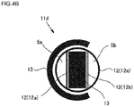
- Fig. 1A and the like the water collecting cells 4b and the plugging members 8 formed in the ceramic filter 1 are schematically shown.
- Fig. 1C shows, for convenience, an arrangement of the rows 8a in which the water collecting cells (the plugging members) are arranged and which is hidden by through channel division means 15.
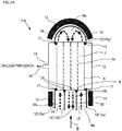
- the ceramic filter 1 is preferably received in a casing 12 and utilized as each of filter devices 11a to 11f as shown in Fig. 1A , Fig. 1B and the like.
- the casing 12 receives the ceramic filter 1, and forms an introduction path 16a to introduce the mixed fluid 10 into the ceramic filter 1, an intermediate path 16b to return and reintroduce, into the ceramic filter 1, the mixed fluid 10 which is being treated, and a discharge path 16c to discharge a treated fluid 30 from the ceramic filter 1.
- the casing 12 also functions as a disposing place of after-mentioned heating means 13 and a connecting place (a decompression port 14) of decompressing means.
- the mixed fluid 10 to be treated is allowed to flow only in one direction from the first end face 2 as an inflow side end face to the second end face 3 as an outflow side end face of the ceramic filter 1, and is filtered.
- the mixed fluid 10 undergoes, at least once, a passing process of passing through an outward path 5a in which the mixed fluid flows from the first end face 2 to the second end face 3 of the ceramic filter 1, returning, and passing through a return path 5b in which the mixed fluid flows from the second end face 3 to the first end face 2.
- such a passing process may be performed in one reciprocation as shown in, e.g., Fig. 1A , Fig. 3A , and Fig. 5A , two reciprocations as shown in Fig. 4A , or more.
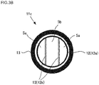
- the filter device 11c shown in Fig. 3A the mixed fluid 10 flows in from each of two introduction paths 16a and returns, and hence, the number of returning times is one, but the fluids from two directions join each other to be stirred, so that a stirring effect enhances.
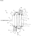
- the filter device of the present invention may only have at least one set of the outward path 5a and the return path 5b constituting a pair with the outward path 5a. For example, as shown in Fig.
- the introduction path 16a and the discharge path 16c may be formed in the different end faces of the ceramic filter 1, respectively, to have the passing process of one reciprocation and half or two reciprocations and half.
- the passing process may be discontinued halfway to dispose a plurality of mutually independent passing routes, and the routes may be used to filter different fluids, respectively. That is, a single filter device may be constituted to simultaneously serve as a plurality of filtering systems.
- the number of the returning times (the number of the intermediate paths) is preferably from 1 to 5, and further preferably from 2 to 4. When the number is smaller than 1, the separation performance deteriorates sometimes. When the number is larger than 5, this structure becomes complicated, and is hard to be manufactured sometimes.
- the plurality of through channels 4 are divided into a plurality of zones including the outward path 5a and the return path 5b by the through channel division means 15.
- the plurality of zones can be formed by the through channel division means 15 suitably disposed in the first end face 2 and/or the second end face 3.
- the casing 12 is preferably disposed on the through channel division means 15, and a flow-through route (the introduction path, the intermediate path and the discharge path) of each of the fluid flowing into the ceramic filter 1 and the fluid flowing out from the ceramic filter 1 is preferably formed by the casing 12.
- each of the introduction path, the intermediate path and the discharge path is preferably formed by a portion of the casing 12 which is disposed on the through channel division means 15, a portion of the casing which is not disposed on the through channel division means 15, or both the portions.
- the casing 12 When the casing 12 is disposed on the through channel division means 15, it is preferable that the casing 12 comes in contact with the through channel division means 15 and is disposed along the through channel division means 15.
- the fluid flows to the ceramic filter 1 through the flow-through route (the introduction path 16a) formed by a part of the casing including at least the portion of the casing which is disposed on the through channel division means 15, and the fluid flows into the zones divided by the through channel division means 15.
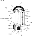
- the number of the zones to be divided may be two as shown in, e.g., Fig. 1A and Fig. 5A , may be three as shown in Fig. 3A , Fig. 4A and Fig. 9A , or may be more.
- a width of the seal means (the through channel division means) is preferably from 0.5 to 1.5 times, further preferably from 0.75 to 1.2 times, and especially preferably from 0.8 to 1.0 time as large as a width of the row in which the water collecting cells are arranged.
- the width of the row in which the water collecting cells are arranged is the shortest distance between circumferences of the filtering cells disposed on both sides adjacent to the water collecting cells.
- a relation between the width of the seal means and the width of the row in which the water collecting cells are arranged is in such a range, and hence, it is possible to prevent "the open ends of the cells adjacent to the water collecting slits" from being closed by the packing (the through channel division means).
- the width of the seal means is a length in "a direction perpendicular to a longitudinal direction of the seal means and parallel to the end face when the seal means is disposed in the end face of the porous body".
- the through channel division means 15 is disposed "along the row" in the state where the through channel division means 15 is in contact with "the row 8a in which the water collecting cells are arranged" in at least one end face of the porous body. That is, the through channel division means 15 is formed along portions of the end face of the ceramic filter 1 "which are sealed by the plugging members", i.e., portions of the through channels which are not opened. Therefore, when the outward path and the return path are divided, the outward path and the return path are not closed by the through channel division means.
- the through channel division means 15 preferably has a linearly extending shape so that the through channel division means can be disposed on "the row in which the water collecting cells are arranged".
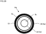
- the conventional filter device 11b shown in Fig. 2A and Fig. 2B is formed so that flow of a fluid returns in the filter device, but through channel division means for forming a structure to return the flow of the fluid is round (see Fig. 2B ). Therefore, open ends of cells opened in an end face are closed by the through channel division means, and the fluid to be treated cannot flow into the closed cells, so that an effective membrane area decreases.
- the through channel division means is formed at such a width that the cells are not closed, seal properties are deteriorated by opened filtering cells facing the seal means, the fluid disadvantageously penetrates beyond the through channel division means, and a desirable flow speed cannot be obtained.
- the conventional filter device 11b shown in Fig. 2A has a constitution similar to the filter device 11a shown in Fig. 1A , except that through channel division means 15 is round and heating means 13 is disposed to surround a casing 12.
- the casing 12 disposed in each of the filter devices 11a to 1 If of the present invention forms the introduction path 16a, the intermediate path 16b and the discharge path 16c to correspond to the through channel division means 15.
- the introduction path 16a is a portion to introduce the mixed fluid 10 into the outward path 5a.
- the intermediate path 16b is a portion to return the mixed fluid 10 which is being treated and reintroduce the fluid into the ceramic filter 1.
- the discharge path 16c is a portion to discharge the treated fluid 30 from the ceramic filter 1.
- the discharge path 16c is preferably positioned on a side opposite to the introduction path 16a via the ceramic filter 1.
- main causes for the polarization are, in a contact interface between the fluid to be treated and the separation membrane (i.e., an inner peripheral portion of each cell), (1) a difference between an inner temperature and an outer temperature of the fluid flowing through the cells due to vaporization heat of the permeable substance which has permeated the separation membrane and (2) a difference between an inner concentration and an outer concentration in "the concentration of the permeable substance" in the fluid flowing through the cells due to the permeation of the permeable substance through the separation membrane.
- the filter when the flow speed lowers, the temperature and the concentration locally lower in the contact interface, and hence, the filter cannot exert any intrinsic performance. Therefore, for the purpose of preventing the separation performance of the filter from being deteriorated, it is necessary to acquire a high flow rate, i.e., a high flow speed in accordance with a sectional area of the filter, thereby mixing the fluids in the cells to dissolve the polarization. Further, it is preferable that the high flow speed is acquired to cause turbulence and that the supply fluids are sufficiently mixed to dissolve the polarization.
- the filter device of the present invention as compared with the conventional filter device, a sectional area of a portion through which the fluid passes during the filtering is smaller, and hence, even when the flow rate of the supply fluid is small, the high flow speed can be acquired. In consequence, it is possible to realize downsizing of a pump and reduction of running cost. Additionally, in the method for using the ceramic filter and the filter device of the present invention, the fluid is stirred in the portion (the intermediate path) in which the fluid is returned. In consequence, the fluid which has dissolved the polarization in at least the intermediate path can be allowed to flow into the return path, and the separation performance improves.
- the fluids flowing out from the through channels are returned to flow into the return path, but before that, in the intermediate path, the fluids flowing out from the respective cells join one another and a flow direction varies, and hence, the fluids are forcibly stirred (joined and stirred) regardless of the flow speed given to the fluid, so that the polarization can be dissolved. Therefore, especially on conditions that a supply amount of the fluid is small, e.g., even on conditions that the fluid cannot flow out from a laminar flow region (Reynolds number of 2100 or less) even when the flow speed is heightened by dividing the abovementioned through channels, the polarized fluid to be treated can be returned to the uniform fluid in at least the intermediate path.
- a laminar flow region Reynolds number of 2100 or less
- a capacity of the intermediate path 16b is preferably from 5 to 50% and further preferably from 8 to 30% of a total capacity (a through channel capacity) of the filtering cells 4a facing the intermediate path 16b.
- the through channel capacity is the total of the capacities of the respective through channels.
- a conventional filter device 11 shown in Fig. 6 has a mechanism in which the mixed fluid 10 is beforehand heated, before the mixed fluid 10 flows from the first end face 2 of the filter 1 into the ceramic filter 1. Further, the heating means 13 is disposed in a portion of the casing 12 before the first end face 2.
- the mixed fluid 10 is preferably beforehand heated before the mixed fluid 10 flows into each of the outward path 5a and the return path 5b. That is, each of the filter devices 11a to 11e of the present invention preferably includes the plurality of heating means 13 for heating the mixed fluid 10 before the mixed fluid flows into each of the outward path 5a and the return path 5b.
- the heating means 13 there is not any special restriction on the heating means 13 as long as the heating means 13 is capable of applying desirable heat to the mixed fluid 10, but it is preferable to use an electric heater, a heat exchanger or the like. There is not any special restriction on a heating timing in a range where the mixed fluid 10 having a required temperature is introduced into the ceramic filter 1, but the mixed fluid 10 is preferably heated immediately before introduced, so that the heat, which is applied to the mixed fluid 10 and escapes until the mixed fluid 10 is introduced into the ceramic filter 1, does not incur deterioration of an energy efficiency.
- the heating means 13 is preferably disposed in a place as close as possible to the mixed fluid 10 to be heated and the ceramic filter 1 into which the mixed fluid 10 is to be introduced.
- the heating means 13 is preferably disposed as close as possible to the end face of the ceramic filter 1, in at least a part of a portion of the casing 12 which forms each of the introduction path 16a and the intermediate path 16b.
- the heating means be disposed away from the ceramic filter 1.
- fluid conveying means connecting the heat exchanger to the introduction path 16a and the intermediate path 16b is preferably made of a high heat insulating material.
- At least a portion of the casing 12 which is interposed between the heating means 13 and the mixed fluid 10 is preferably made of a high heat conductive material 12a.
- the high heat conductive material 12a include carbon, aluminum, iron, and stainless steel.
- aluminum is especially preferably used from the viewpoints of easiness of shape machining, a high heat conductivity, a high corrosion resistance, and light weight properties.
- At least a portion of the casing 12 in which the mixed fluid 10 and the treated fluid 30 pass by each other, i.e., a portion of the casing which divides the introduction path 16a and the discharge path 16c is preferably made of a low heat conductive material 12b for the purpose of preventing the heat applied to the mixed fluid 10 from being taken to a treated fluid 30 side.
- the low heat conductive material 12b include a silicone rubber, a fluororesin, glass, and a double wall material via air or vacuum.
- a vacuum double wall material is especially preferably used from the viewpoints of the easiness of the shape machining, a low heat conductivity, and the high corrosion resistance.
- the material may be the same material as in the seal means for use in the through channel division means 15 and, for example, a silicone rubber or a fluororesin is preferable. It is to be noted that, in Fig. 1A to Fig. 6 , the low heat conductive material 12b is shown by double lines for convenience, but in the actual filter devices 11a to 11e of the present invention, the low heat conductive material 12b is not limited to a double structure as described above.
- the present invention when the mixed fluid 10 flowing into the ceramic filter 1 is always heated, the separation performance is preferably maintained to be high.
- the conventional filter device a large amount of the fluid has to be collectively heated and introduced, and hence, enlargement and cost increase of not only the pump but also a heater as the heating means cannot be avoided.
- the present invention has the heating means, the present invention overcomes these problems of the conventional filtering system while using the heretofore known ceramic filter.
- the inside of the casing 12 in which the ceramic filter 1 is received may be decompressed through the decompression port 14 by use of the decompressing means.
- the inside of the casing 12 is decompressed, and hence, a pressure difference is made between a filtering cell 4a side of the ceramic filter 1 and a water collecting cell 4b side or a circumferential wall side, and separation of a permeable substance 20 for the purpose of allowing permeation through the separation membrane is promoted, so that recovery is preferably facilitated.
- each of the filter devices 11a to 11e of the present invention may include the decompressing means for controlling a pressure in the casing 12 to promote the separation of the target permeable substance 20.
- the decompressing means is preferably disposed in a part (the decompression port 14) of a portion of the casing 12 which covers the ceramic filter 1.
- heretofore known means such as a vacuum pump is usable.
- the filter device itself becomes large-scaled, and restrictions are imposed on a disposing place and the like from the viewpoint of a size and a weight.
- the plurality of ceramic filters as well as the casings, heating means and decompressing means matched with the ceramic filters are required to raise the problem that the number of the components increases and cost heightens.
- each ceramic filter as seal positions 17 of the through channels through which the mixed fluid passes, to an internal space of the casing which is to be decompressed, increases, there heightens the risk that leakage from a system of the mixed fluid occurs to generate a loss of the mixed fluid, decompressing means such as the vacuum pump is adversely affected, or the leaked mixed fluid catches fire. Therefore, the present invention has remarkable merits even as compared with the conventional filter device in which the abovementioned plurality of ceramic filters are used.
- alumina was used as aggregate particles, and a monolith type of ceramic filter was prepared.
- the obtained ceramic filter had a round pillar shape with an outer diameter of 90 mm and a length of 100 mm.
- 500 cells of through channels were disposed, and a diameter of each cell was 2.5 mm.
- open ends water collecting slits
- the end face of the ceramic filter was sealed with a glass seal.
- the obtained filter was incorporated into such a casing as shown in Fig. 1A , to prepare a filter device.
- thermos structure As a casing material, aluminum was used, and a low heat conductive material was formed into a thermos structure the inside of which was made a vacuum with double walls.
- channel division means 15 a packing (seal means) made of a hard rubber), which was in contact with "a row 8a in which water collecting cells (plugging members) were arranged" in one end face of the porous body, was disposed "along the row” (see Fig. 1C ).
- the prepared filter device was used to carry out a penetration vaporization separation test of a mixed liquid (a mixed fluid) having a mass ratio of 1:1:1 of ethanol, normal octane and orthoxylene.
- a heater temperature was set to 70°C
- a secondary side vacuum pressure was set to 50 Torr
- a liquid flow rate was set to 3.7 L/minute
- an amount of the fluid which permeated a membrane after elapse of a certain time was calculated as Flux (kg/m 2 ⁇ h).
- an IPA concentration in the permeated mixed liquid was measured, and a separation coefficient ⁇ (1/(1-ethanol permeation concentration)) was calculated. Table 1 shows the result. [Table 1] No.
- Example 1 1 0.050 250 4.3 2.8
- Example 2 1 0.050 250 4.5 3.2
- Example 3 3 0.100 500 5.9 8.3
- Example 4 1 0.050 250 4.1 2.9
- Example 5 2 0.075 375 4.3 4.0 Comparative Ex. 1 0 0.025 125 2.4 2.1 Comparative Ex. 2 1 0.050 250 3.2 2.4
- a filter device was prepared on conditions similar to those of Example 1, except that a casing structure was formed as shown in Fig. 3A , and a penetration vaporization separation test of a mixed liquid was carried out. Table 1 shows the result.
- a filter device was prepared on conditions similar to those of Example 1, except that a casing structure was formed as shown in Fig. 4A , and a penetration vaporization separation test of a mixed liquid was carried out. Table 1 shows the result.
- a filter device was prepared on conditions similar to those of Example 1, except that a casing structure was formed as shown in Fig. 5A , and a penetration vaporization separation test of a mixed liquid was carried out. Table 1 shows the result.
- a filter device was prepared on conditions similar to those of Example 1, except that a casing structure was formed as shown in Fig. 9A , and a penetration vaporization separation test of a mixed liquid was carried out. Table 1 shows the result.
- a filter device was prepared on conditions similar to those of Example 1, except that a casing structure was formed as shown in Fig. 6 , and a penetration vaporization separation test of a mixed liquid was carried out. Table 1 shows the result.
- a filter device was prepared on conditions similar to those of Example 1, except that a casing structure was formed as shown in Fig. 2A . Open ends of part of through channels in one end face of a porous body were closed by through channel division means. A penetration vaporization separation test of a mixed liquid was carried out by using the obtained filter device. Table 1 shows the result.
- a method for using a ceramic filter and a filter device according to the present invention are suitably utilized as means for separating a component as a part of a mixture by a penetration vaporization process.
- 10 mixed fluid, 11, 11a, 11b, 11c, 11d, 11e and 11f: filter device, 12: casing, 12a: high heat conductive material, 12b: low heat conductive material, 13: heating means, 14: decompression port, 15: through channel division means, 16a: introduction path, 16b: intermediate path, 16c: discharge path, 17: seal position, 20: permeable substance, 30: treated fluid, 31: separation membrane, 35: supporter, and 36: intermediate layer.
Landscapes
- Chemical & Material Sciences (AREA)
- Chemical Kinetics & Catalysis (AREA)
- Engineering & Computer Science (AREA)
- Water Supply & Treatment (AREA)
- Separation Using Semi-Permeable Membranes (AREA)
- Filtering Materials (AREA)
Description
- The present invention relates to a method for using a ceramic filter, and a filter device including a ceramic filter.
- In recent years, a filter made of ceramic has been used to selectively separate and recover an only specific component from a mixture of multiple components. The filter made of ceramic is excellent in mechanical strength, durability, corrosion resistance and the like as compared with a filter made of organic polymer, and hence, the filter is preferably applied as a separation membrane which separates a liquid or gas mixture at a molecule level in a broad field such as a petrochemistry field, a natural gas plant, or a medicine or food field.
- In such a filter made of ceramic (referred to as the ceramic filter), for the purpose of improving a permeation performance while acquiring a separation performance, it is necessary to enlarge an effective membrane area (the area of the separation membrane which comes in contact with a fluid to be treated), and for this necessity, a filter shape is desirably of a monolith type (or a honeycomb type). The monolith type of filter has advantages that the filter is hard to bend, is easy to seal, can be made compact and can achieve cost reduction, and the like, as compared with a tube type of filter. In many cases, the monolith type of filter includes a porous supporter having a round pillar-like outer shape and having therein a large number of parallel through channels (also referred to as cells) formed in an axial direction of the filter, and further, a separation membrane having smaller pore diameters than those of the porous supporter is formed on an inner wall surface in which the cells are to be formed.
- An example of a prior document in which the conventional monolith type (or honeycomb type) of ceramic filter is disclosed is
Patent Document 1. In addition, an example of a prior document in which a fluid separating method using such a filter is disclosed isPatent Document 2. - In addition, there is disclosed a filter (a membrane container) in which a flow speed of the fluid flowing through the filter is increased to improve the separation performance (e.g., see Patent Document 3).
-
- [Patent Document 1]
WO 2008/056803 - [Patent Document 2] Domestic re-publication of
PCT international application No. 2010-070992 - [Patent Document 3]
JP-A-2012-61442 -
WO 2004/091756 A1 discloses a ceramic filter where a plurality of through channels is present in a pillar-shaped body extending from a first end face to a second end face. Open ends of both the end faces of the through channels are opened, but in part of the through channels, the open ends of both the end faces are plugged by plugging members. - In such a method of separating a substance having a high volatility as disclosed in
Patent Document 2, to further improve a separation performance, there is used means for beforehand heating a mixed fluid to be treated. In general, when a flow rate of a supply fluid is low, a flow speed is lowered, and a filtering time lengthens to cause polarization in through channels (cells), thereby deteriorating the separation performance. It is to be noted that main causes for the polarization are (1) a difference between an inner temperature and an outer temperature of the fluid flowing through the cells (a difference in temperature between a central portion and the vicinity of a separation membrane) due to vaporization heat of a permeable substance which has permeated the separation membrane, and (2) a difference between an inner concentration and an outer concentration (a difference in concentration between the central portion and the vicinity of the separation membrane) in "the concentration of the permeable substance" in the fluid flowing through the cells due to permeation of the permeable substance through the separation membrane. That is, when the flow speed lowers, the temperature and the concentration locally lower in a contact interface, and hence, a filter cannot exert any intrinsic performance. Therefore, for the purpose of preventing the separation performance of the filter from being deteriorated, it is necessary to mix the fluids in the cells, thereby dissolving polarization. However, generally for the purpose of causing turbulence in the cells, it is necessary to acquire a high flow rate, i.e., a high flow speed in accordance with a sectional area of the filter. This necessity requires a pump of a high capability, but the pump of the high capability invites the problem of enlargement of the pump and increase of energy and cost required for an operation of the pump are incurred. Specifically, during the flowing in a round tube, Reynolds number Re (= Duρ/µ) of 4000 or more is required, and particularly in a monolith type of filter having a small inner diameter D, a high flow speed u is required. Here, D is an inner diameter of each cell, u is an average flow speed, ρ is a density of the fluid, and µ is a viscosity of the fluid. - Additionally, in a conventional separating method, the mixed fluid to be treated is allowed to flow only in one direction from an inflow side end face to an outflow side end face of a filter, and is filtered. However, when such a fluid of the high flow rate corresponding to the sectional area of the filter as described above is filtered, temperature drop of the fluid in a filtering process easily occurs. Therefore, it is necessary to beforehand sufficiently apply heat to the fluid to be treated, but there have been incurred the problems such as installation of a large heater and increase of energy or cost required for an operation of the heater.
- On the contrary, in a membrane container described in
Patent Document 3, a flow path of the fluid is returned in the membrane container with the intension of increasing the flow speed of the fluid to be treated. Further, the separation performance is intended to be improved in this way. However, in the membrane container described inPatent Document 3, a round returning portion for use in returning the fluid is disposed in an end face of a membrane container main body. In consequence, a portion of the membrane container end face in which the returning portion is disposed cannot come in contact with a membrane due to the flowing fluid, which has raised the problem that a treatment amount of the fluid (an effective membrane area) becomes smaller. - An object of the present invention is to provide a method for using a ceramic filter and a filter device in which a high separation performance is realized while maintaining a high treatment amount.
- The object is solved by features defined in
claims - The present inventors have divided through channels of a ceramic filter into an outward path and a return path by through channel division means, allowing a mixed fluid to reciprocate through the same filter once or more, and have disposed the through channel division means on plugging portions of water collecting slits. Further, the present inventors have found that the above problem can thus be solved. That is, according to the present invention, the following method for using a ceramic filter and a filter device are provided. It is to be noted that, here, "water collection" means collecting of a liquid and/or vapor which has permeated a membrane, and an object of the collection is not limited to "water" and may be any substance as long as the substance permeates the membrane. Examples of the substance which has permeated the membrane include water, steam, hydrogen, nitrogen, carbon dioxide, alcohol, an organic liquid medium, and an organic molecule.
- [1] A method for using a ceramic filter that is used to separate a target permeable substance from a mixed fluid and that includes a pillar-shaped porous body having a plurality of through channels extending through the porous body from a first end face to a second end face and formed in rows and having a circumferential surface, and a separation membrane disposed on each of inner wall surfaces of at least part of the plurality of through channels, wherein one or some of the plurality of through channels are water collecting cells whose open ends in the first end face and the second end face are plugged by plugging members, further wherein water collecting slits is disposed to open in the circumferential surface of the porous body so that the water collecting cells communicate with an external space, and wherein the water collecting cells are arranged to form at least one row in end faces of the porous body, the method for using the ceramic filter including: disposing through channel division means along a row in which the water collecting cells are arranged in at least one of the end faces of the porous body in a state where the through channel division means is in contact with the row, and dividing the plurality of through channels into a plurality of zones including an outward path and a return path by use of the through channel division means so that the mixed fluid undergoes, at least once, a passing process of passing through the outward path in which the mixed fluid flows from the first end face to the second end face of the ceramic filter, returning and then passing through the return path in which the mixed fluid flows from the second end face to the first end face, and collecting the target permeable substance after the target permeable substance permeates the separation membrane.
- [2] The method for using the ceramic filter according to [1], including decompressing an inside of a casing in which the ceramic filter is received by using decompressing means.
- [3] The method for using the ceramic filter according to [1] or [2], including heating the mixed fluid before the mixed fluid flows into each of the outward path and the return path.
- [4] The method for using the ceramic filter according to any one of [1] to [3], including disposing, as the through channel division means, seal means for preventing the mixed fluid from penetrating beyond the through channel division means at least an inflow side end face.
- [5] The method for using the ceramic filter according to [4], including disposing, as the through channel division means, the seal means in each of the first end face and the second end face.
- [6] The method for using the ceramic filter according to [5], wherein a width of the seal means is from 0.5 to 1.5 times as large as a width of the row in which the water collecting cells are arranged.
- [7] The method for using the ceramic filter according to any one of [1] to [6], wherein the number of times of the returning is from 1 to 5.
- [8] The method for using the ceramic filter according to any one of [1] to [7], wherein the separation membrane is a membrane by which alcohol is separable from an organic liquid medium containing the alcohol.
- [9] The method for using the ceramic filter according to any one of [1] to [8], wherein the separation membrane is a hybrid silica membrane having an organic functional group.
- [10] A filter device including: a ceramic filter that includes a pillar-shaped porous body having a plurality of through channels extending through the porous body from a first end face to a second end face and formed in rows and having a circumferential surface, and a separation membrane disposed on each of inner wall surfaces of at least part of the plurality of through channels, wherein one or some of the plurality of through channels are water collecting cells whose open ends in the first end face and the second end face are plugged by plugging members, and further wherein water collecting slits are disposed to open in the circumferential surface of the porous body so that the water collecting cells communicate with an external space; and a casing which receives the ceramic filter and forms an introduction path to introduce a mixed fluid into the ceramic filter, an intermediate path to return and reintroduce, into the ceramic filter, the mixed fluid which is being treated, and a discharge path to discharge the treated fluid from the ceramic filter, wherein the plurality of through channels have at least one set of an outward path in which the mixed fluid flows from the first end face to the second end face and a return path in which the mixed fluid returns and flows from the second end face to the first end face, the water collecting cells are arranged to form at least one row in end faces of the porous body, through channel division means is disposed along the row in which the water collecting cells are arranged in at least one of the end faces of the porous body in a state where the through channel division means is in contact with the row, and the outward path and the return path are divided by the through channel division means.
- [11] The filter device according to [10], wherein the casing has decompressing means for controlling an inner pressure of the casing to promote separation of a target permeable substance.
- [12] The filter device according to [10] or [11], including a plurality of heating means for heating the mixed fluid before the mixed fluid flows into each of the outward path and the return path.
- [13] The filter device according to any one of [10] to [12], wherein the plurality of through channels are divided into a plurality of zones including the outward path and the return path, and the plurality of zones are formed by the through channel division means disposed in the first end face and the second end face.
- [14] The filter device according to any one of [10] to [13], wherein the through channel division means is seal means disposed in each of the first end face and the second end face.
- [15] The filter device according to [14], wherein a width of the seal means is from 0.5 to 1.5 times as large as a width of the row in which the water collecting cells are arranged.
- [16] The filter device according to any one of [10] to [15], wherein the number of times of the returning is from 1 to 5.
- [17] The filter device according to any one of [10] to [16], wherein the separation membrane is a membrane by which alcohol is separable from an organic liquid medium containing the alcohol.
- [18] The filter device according to any one of [10] to [17], wherein the separation membrane is a hybrid silica membrane having an organic functional group.
- [19] The filter device according to any one of [10] to [18], wherein a capacity of the intermediate path is from 5 to 50% of a through channel capacity.
- [20] The filter device according to any one of [10] to [19], wherein the discharge path is positioned on a side opposite to the introduction path via the ceramic filter.
- In a method for using a ceramic filter and a filter device of the present invention, through channels of the ceramic filter are divided into a plurality of zones. Consequently, in the present inventions, as compared with a case where a mixed fluid is allowed to pass through an entire ceramic filter only in one direction as in a conventional method for using the ceramic filter, a sectional area of an end face into which the mixed fluid flows becomes smaller, and a flow speed in cells relatively becomes faster, so that a high mixed state (Reynolds number) can be obtained. Therefore, in the present invention, even when a supply amount of the mixed fluid is the same, a higher flow speed can be obtained, and a separation performance is hard to deteriorate, thereby enabling downsizing of a pump which feeds out a fluid to be treated and reduction of an energy amount required for an operation of the pump. Additionally, in the method for using the ceramic filter and the filter device of the present invention, in a state where through channel division means is in contact with "a row in which water collecting cells are arranged" in at least one end face of a porous body, the through channel division means is disposed along the "row". Further, an outward path and a return path are divided by the through channel division means. Therefore, when the outward path and the return path are divided, the outward path and the return path (open ends of the through channels) are not closed by the through channel division means. In consequence, it is possible to prevent decrease of a treatment amount of the fluid (an effective membrane area) due to the disposing of the through channel division means in the end face of the porous body. Additionally, in the method for using the ceramic filter and the filter device of the present invention, in a portion (an intermediate path) in which the fluid is returned, the fluid which has been polarized in the outward path cells is stirred. In consequence, the fluid whose polarization is dissolved in at least the intermediate path can be allowed to flow into the return path, to improve the separation performance. As to an effect of the above stirring, the stirring is effective especially in a case where the supply amount of the mixed fluid is small. Specifically, in a case where the Reynolds number does not reach 4000 even when the through channels are divided into the large number of zones to heighten the flow speed, insides of the cells do not reach turbulence and the polarization cannot sufficiently be dissolved. However, in the present invention, the fluid can forcibly be stirred to dissolve the polarization regardless of the flow speed in the intermediate path.
-
-
Fig. 1A is a schematic view showing one embodiment of a filter device of the present invention; -
Fig. 1B is a schematic view of the filter device shown inFig. 1A and seen from an arrow-A direction; -
Fig. 1C is a plan view schematically showing a state that through channel division means is disposed along "a row in which water collecting cells are arranged" in an end face of a ceramic filter in a state where the through channel division means is in contact with the row; -
Fig. 2A is a schematic view showing a conventional filter device; -
Fig. 2B is a schematic view of a filter device shown inFig. 2A and seen from an arrow-B direction; -
Fig. 3A is a schematic view showing another embodiment of the filter device of the present invention; -
Fig. 3B is a schematic view of a filter device shown inFig. 3A and seen from an arrow-C direction; -
Fig. 4A is a schematic view showing still another embodiment of the filter device of the present invention; -
Fig. 4B is a schematic view of a filter device shown inFig. 4A and seen from an arrow-D direction; -
Fig. 5A is a schematic view showing a further embodiment of the filter device of the present invention; -
Fig. 5B is a schematic view of a filter device shown inFig. 5A and seen from an arrow-E direction; -
Fig.6 is a schematic view showing one embodiment of the conventional filter device; -
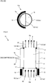
Fig. 7 is a schematic perspective view showing one embodiment of a monolith type of filter, a part of which is cut out; -
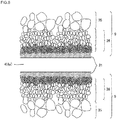
Fig. 8 is an enlarged sectional view showing the vicinity of one of filtering cells shown inFig. 7 ; -
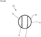
Fig. 9A is a schematic view showing a still further embodiment of the filter device of the present invention; and -
Fig. 9B is a schematic view of the filter device shown inFig. 9A and seen from an arrow-F direction. - Hereinafter, embodiments of the present invention will be described with reference to the drawings. The present invention is not limited to the following embodiments, and change, modification and improvement can be added to the present invention without departing from the gist of the invention.
- As a ceramic filter for use in a method for using the ceramic filter and a filter device of the present invention, a heretofore known filter is usable, but it is preferable to use such a monolith type of
ceramic filter 1 as shown in, e.g.,Fig. 7 . In this technical field, the monolith type indicates a structure where a plurality of through channels are present in a pillar-shaped body as in a lotus root. - The monolith type of
ceramic filter 1 shown inFig. 7 includes aporous body 9 having afirst end face 2, asecond end face 3, and acircumferential surface 6. Theporous body 9 has a round pillar-like outer shape and has therein a large number of throughchannels 4 extending through the porous body from thefirst end face 2 to thesecond end face 3 and formed in rows parallel to one another. Open ends of both the end faces of the throughchannels 4 are opened, but in part of the through channels, the open ends of both the end faces are plugged by pluggingmembers 8. In the throughchannel 4 in which the open ends of both the end faces are opened, aseparation membrane 31 is disposed on an inner wall surface of the through channel, and the through channel functions as afiltering cell 4a. Additionally, in the throughchannel 4 in which the open ends of both the end faces are plugged by pluggingmembers 8, theseparation membrane 31 does not have to be disposed on the inner wall surface, and the through channel functions as awater collecting cell 4b. The pluggingmembers 8 can be made of the same material as in theporous body 9. Additionally, in the end face of theceramic filter 1, the pluggingmembers 8 are arranged to form at least one row (arow 8a in which the water collecting cells (the plugging members) are arranged). - In the
circumferential surface 6,water collecting slits 7 are disposed so that thewater collecting cells 4b communicate with an external space. Thus, thewater collecting slits 7 are disposed, and hence, it is possible to prevent increase of a pressure loss and decrease of a permeation amount due to the increase when a mixed fluid 10 passes through theporous body 9. In this case, a length of the pluggingmember 8 may be such a length as to reach thewater collecting slit 7. That is, there is a mechanism for themixed fluid 10 to be separated that themixed fluid 10 enters thefiltering cell 4a, and afterward, a permeable substance of a part of the mixed fluid selectively permeates theseparation membrane 31, and is discharged to the outside of theceramic filter 1 through the water collecting slit 7 or theporous body 9. In addition, although not shown in the drawing, thefirst end face 2 or thesecond end face 3 is preferably sealed by, e.g., a glass seal or a metal seal. In consequence, when themixed fluid 10 flows into thefiltering cell 4a, it is possible to prevent themixed fluid 10 from being mixed with passed fluid which penetrates from thefirst end face 2 or thesecond end face 3 into theporous body 9, and passes through theseparation membrane 31 there. The end face through which themixed fluid 10 penetrates into theporous body 9 is an inflow side end face. - In the
ceramic filter 1 shown inFig. 7 , a sectional shape of the throughchannel 4 is round, but in the method for using the ceramic filter and the filter device according to the present invention, the sectional shape of the throughchannel 4 may be any polygonal shape. -
Fig. 8 is an enlarged sectional view showing the enlarged vicinity of thefiltering cell 4a shown inFig. 7 . As shown inFig. 8 , theporous body 9 is constituted of asupporter 35, and anintermediate layer 36 superimposed on thesupporter 35 and including one or more layers having different average pore diameters. Further, in thefiltering cell 4a, theseparation membrane 31 is disposed on the surface of theintermediate layer 36. The number of the layers forming theintermediate layer 36 and the average pore diameter in each layer can suitably be selected in accordance with properties or use of the fluid to be treated, in view of a separation performance. - There is not any special restriction on the
separation membrane 31 as long as it is possible to separate the mixed fluid including a mixed gas, a mixed liquid or the like, and the membrane may suitably be selected from a known carbon membrane, a zeolite membrane, a silica membrane, and the like in accordance with a type of fluid to be separated. It is to be noted that, when alcohol is separated from an organic liquid medium containing the alcohol, a hybrid silica membrane having an organic functional group is preferable among these membranes. As the organic functional group, the number of carbon atoms is preferably from 2 to 8, and the group can suitably be selected in accordance with a type of alcohol to be separated. Furthermore, the organic functional group may be a chain alkyl group or an annular aryl group. When the alcohol to be separated is ethanol, an octyl group, a phenyl group or a tolyl group is especially preferable from the viewpoint that a selection ratio is high. - Next, the method for using the ceramic filter and the filter device of the present invention will be described. As described above, the present invention provides a method and a device for use in separating a target permeable substance from the mixed fluid by use of the ceramic filter including the porous body and the separation membrane disposed on each of the inner wall surfaces of at least part of the plurality of through channels. The porous body is a pillar-shaped structure body in which there are disposed the plurality of through channels extending through the body from the first end face to the second end face and formed in the rows. The method for using the ceramic filter of the present invention is preferably a method using the filter device of the present invention.
Fig. 1A to Fig. 1C ,Fig. 3A to Fig. 5B ,Fig. 9A andFIG. 9B are schematic views showing the respective embodiments of the filter device of the present invention, andFig. 2A ,Fig. 2B andFig. 6 are schematic views showing one embodiment of a conventional filter device. InFig. 1A and the like, thewater collecting cells 4b and the pluggingmembers 8 formed in theceramic filter 1 are schematically shown. Additionally,Fig. 1C shows, for convenience, an arrangement of therows 8a in which the water collecting cells (the plugging members) are arranged and which is hidden by through channel division means 15. - For example, when the monolith type of
ceramic filter 1 shown inFig. 7 is used in the present invention, theceramic filter 1 is preferably received in acasing 12 and utilized as each offilter devices 11a to 11f as shown inFig. 1A ,Fig. 1B and the like. Thecasing 12 receives theceramic filter 1, and forms anintroduction path 16a to introduce themixed fluid 10 into theceramic filter 1, anintermediate path 16b to return and reintroduce, into theceramic filter 1, themixed fluid 10 which is being treated, and adischarge path 16c to discharge a treated fluid 30 from theceramic filter 1. In addition, thecasing 12 also functions as a disposing place of after-mentioned heating means 13 and a connecting place (a decompression port 14) of decompressing means. - As shown in
Fig. 6 , in a conventional fluid separating method, themixed fluid 10 to be treated is allowed to flow only in one direction from thefirst end face 2 as an inflow side end face to thesecond end face 3 as an outflow side end face of theceramic filter 1, and is filtered. On the other hand, in the filter device of the present invention, as shown inFig. 1A ,Fig. 1B and the like, themixed fluid 10 undergoes, at least once, a passing process of passing through anoutward path 5a in which the mixed fluid flows from thefirst end face 2 to thesecond end face 3 of theceramic filter 1, returning, and passing through areturn path 5b in which the mixed fluid flows from thesecond end face 3 to thefirst end face 2. That is, such a passing process may be performed in one reciprocation as shown in, e.g.,Fig. 1A ,Fig. 3A , andFig. 5A , two reciprocations as shown inFig. 4A , or more. It is to be noted that, in thefilter device 11c shown inFig. 3A , themixed fluid 10 flows in from each of twointroduction paths 16a and returns, and hence, the number of returning times is one, but the fluids from two directions join each other to be stirred, so that a stirring effect enhances. In addition, the filter device of the present invention may only have at least one set of theoutward path 5a and thereturn path 5b constituting a pair with theoutward path 5a. For example, as shown inFig. 9A andFig. 9B , theintroduction path 16a and thedischarge path 16c may be formed in the different end faces of theceramic filter 1, respectively, to have the passing process of one reciprocation and half or two reciprocations and half. It is to be noted that, in the filter device having the passing process of 1.5 or more reciprocations, the passing process may be discontinued halfway to dispose a plurality of mutually independent passing routes, and the routes may be used to filter different fluids, respectively. That is, a single filter device may be constituted to simultaneously serve as a plurality of filtering systems. The number of the returning times (the number of the intermediate paths) is preferably from 1 to 5, and further preferably from 2 to 4. When the number is smaller than 1, the separation performance deteriorates sometimes. When the number is larger than 5, this structure becomes complicated, and is hard to be manufactured sometimes. - To realize such a passing process, the plurality of through
channels 4 are divided into a plurality of zones including theoutward path 5a and thereturn path 5b by the through channel division means 15. The plurality of zones can be formed by the through channel division means 15 suitably disposed in thefirst end face 2 and/or thesecond end face 3. When the through channels are divided by the through channel division means 15, as shown inFig. 1A and the like, thecasing 12 is preferably disposed on the through channel division means 15, and a flow-through route (the introduction path, the intermediate path and the discharge path) of each of the fluid flowing into theceramic filter 1 and the fluid flowing out from theceramic filter 1 is preferably formed by thecasing 12. It is to be noted that each of the introduction path, the intermediate path and the discharge path is preferably formed by a portion of thecasing 12 which is disposed on the through channel division means 15, a portion of the casing which is not disposed on the through channel division means 15, or both the portions. When thecasing 12 is disposed on the through channel division means 15, it is preferable that thecasing 12 comes in contact with the through channel division means 15 and is disposed along the through channel division means 15. In consequence, the fluid flows to theceramic filter 1 through the flow-through route (theintroduction path 16a) formed by a part of the casing including at least the portion of the casing which is disposed on the through channel division means 15, and the fluid flows into the zones divided by the through channel division means 15. Further, afterward, the fluid is discharged through each zone and the intermediate path and finally through the discharge path. The number of the zones to be divided may be two as shown in, e.g.,Fig. 1A andFig. 5A , may be three as shown inFig. 3A ,Fig. 4A andFig. 9A , or may be more. There is not any special restriction on the through channel division means 15 as long as the through channel division means 15 is seal means for cutting off the penetration of the fluid from divided positions of thefirst end face 2 and thesecond end face 3, but it is possible to use a packing or a seal jig made of a material such as a hard rubber or a fluororesin. A width of the seal means (the through channel division means) is preferably from 0.5 to 1.5 times, further preferably from 0.75 to 1.2 times, and especially preferably from 0.8 to 1.0 time as large as a width of the row in which the water collecting cells are arranged. Here, the width of the row in which the water collecting cells are arranged is the shortest distance between circumferences of the filtering cells disposed on both sides adjacent to the water collecting cells. Thus, a relation between the width of the seal means and the width of the row in which the water collecting cells are arranged is in such a range, and hence, it is possible to prevent "the open ends of the cells adjacent to the water collecting slits" from being closed by the packing (the through channel division means). When the rate is smaller than 0.5 time, it is hard to carry out the sealing sometimes. When the rate is larger than 1.5 times, the open ends of the opened through channels are closed sometimes. Here, the width of the seal means is a length in "a direction perpendicular to a longitudinal direction of the seal means and parallel to the end face when the seal means is disposed in the end face of the porous body". - In addition, as shown in
Fig. 1C , the through channel division means 15 is disposed "along the row" in the state where the through channel division means 15 is in contact with "therow 8a in which the water collecting cells are arranged" in at least one end face of the porous body. That is, the through channel division means 15 is formed along portions of the end face of theceramic filter 1 "which are sealed by the plugging members", i.e., portions of the through channels which are not opened. Therefore, when the outward path and the return path are divided, the outward path and the return path are not closed by the through channel division means. In consequence, it is possible to prevent decrease of a treatment amount of the fluid (an effective membrane area) due to the disposing of the through channel division means in the end face of the porous body. In addition, the through channel division means 15 preferably has a linearly extending shape so that the through channel division means can be disposed on "the row in which the water collecting cells are arranged". - In addition, the
conventional filter device 11b shown inFig. 2A andFig. 2B is formed so that flow of a fluid returns in the filter device, but through channel division means for forming a structure to return the flow of the fluid is round (seeFig. 2B ). Therefore, open ends of cells opened in an end face are closed by the through channel division means, and the fluid to be treated cannot flow into the closed cells, so that an effective membrane area decreases. On the other hand, if the through channel division means is formed at such a width that the cells are not closed, seal properties are deteriorated by opened filtering cells facing the seal means, the fluid disadvantageously penetrates beyond the through channel division means, and a desirable flow speed cannot be obtained. In addition, if through channels are not formed in a portion in which the through channel division means is disposed so that open ends of the through channels are not closed, the number of the through channels to be formed decreases, and hence, the effective membrane area decreases. It is to be noted that theconventional filter device 11b shown inFig. 2A has a constitution similar to thefilter device 11a shown inFig. 1A , except that through channel division means 15 is round and heating means 13 is disposed to surround acasing 12. - In addition, the
casing 12 disposed in each of thefilter devices 11a to 1 If of the present invention forms theintroduction path 16a, theintermediate path 16b and thedischarge path 16c to correspond to the through channel division means 15. Theintroduction path 16a is a portion to introduce themixed fluid 10 into theoutward path 5a. Theintermediate path 16b is a portion to return themixed fluid 10 which is being treated and reintroduce the fluid into theceramic filter 1. Thedischarge path 16c is a portion to discharge the treated fluid 30 from theceramic filter 1. Thedischarge path 16c is preferably positioned on a side opposite to theintroduction path 16a via theceramic filter 1. In consequence, it is possible to prevent that "when the heating means is used, heat of the fluid flowing through theintroduction path 16a is taken by the treated fluid whose temperature has lowered". In addition, when the device is connected to a piping line, a space to be occupied is easily made smaller. - In general, when a flow rate of a supply fluid is low, a flow speed is lowered, and a filtering time lengthens to cause polarization in the through channels (the cells), thereby deteriorating the separation performance. It is to be noted that main causes for the polarization are, in a contact interface between the fluid to be treated and the separation membrane (i.e., an inner peripheral portion of each cell), (1) a difference between an inner temperature and an outer temperature of the fluid flowing through the cells due to vaporization heat of the permeable substance which has permeated the separation membrane and (2) a difference between an inner concentration and an outer concentration in "the concentration of the permeable substance" in the fluid flowing through the cells due to the permeation of the permeable substance through the separation membrane. That is, when the flow speed lowers, the temperature and the concentration locally lower in the contact interface, and hence, the filter cannot exert any intrinsic performance. Therefore, for the purpose of preventing the separation performance of the filter from being deteriorated, it is necessary to acquire a high flow rate, i.e., a high flow speed in accordance with a sectional area of the filter, thereby mixing the fluids in the cells to dissolve the polarization. Further, it is preferable that the high flow speed is acquired to cause turbulence and that the supply fluids are sufficiently mixed to dissolve the polarization. In the filter device of the present invention, as compared with the conventional filter device, a sectional area of a portion through which the fluid passes during the filtering is smaller, and hence, even when the flow rate of the supply fluid is small, the high flow speed can be acquired. In consequence, it is possible to realize downsizing of a pump and reduction of running cost. Additionally, in the method for using the ceramic filter and the filter device of the present invention, the fluid is stirred in the portion (the intermediate path) in which the fluid is returned. In consequence, the fluid which has dissolved the polarization in at least the intermediate path can be allowed to flow into the return path, and the separation performance improves. In the intermediate path, the fluids flowing out from the through channels are returned to flow into the return path, but before that, in the intermediate path, the fluids flowing out from the respective cells join one another and a flow direction varies, and hence, the fluids are forcibly stirred (joined and stirred) regardless of the flow speed given to the fluid, so that the polarization can be dissolved. Therefore, especially on conditions that a supply amount of the fluid is small, e.g., even on conditions that the fluid cannot flow out from a laminar flow region (Reynolds number of 2100 or less) even when the flow speed is heightened by dividing the abovementioned through channels, the polarized fluid to be treated can be returned to the uniform fluid in at least the intermediate path.
- A capacity of the
intermediate path 16b is preferably from 5 to 50% and further preferably from 8 to 30% of a total capacity (a through channel capacity) of thefiltering cells 4a facing theintermediate path 16b. When the percentage is smaller than 5%, the pressure loss heightens sometimes. When the percentage is larger than 50%, heat is hard to be conducted sometimes in a case where the heating means is used. The through channel capacity is the total of the capacities of the respective through channels. When the plurality of intermediate paths are formed in the flow-through route, the capacity of the individualintermediate path 16b (i.e., the capacity of the oneintermediate path 16b) preferably satisfies the abovementioned numeric range. - A
conventional filter device 11 shown inFig. 6 has a mechanism in which themixed fluid 10 is beforehand heated, before themixed fluid 10 flows from thefirst end face 2 of thefilter 1 into theceramic filter 1. Further, the heating means 13 is disposed in a portion of thecasing 12 before thefirst end face 2. On the other hand, in the filter device of the present invention, as shown in, e.g.,Fig. 1A ,Fig. 1B andFig. 3A toFig. 5B , themixed fluid 10 is preferably beforehand heated before themixed fluid 10 flows into each of theoutward path 5a and thereturn path 5b. That is, each of thefilter devices 11a to 11e of the present invention preferably includes the plurality of heating means 13 for heating themixed fluid 10 before the mixed fluid flows into each of theoutward path 5a and thereturn path 5b. - There is not any special restriction on the heating means 13 as long as the heating means 13 is capable of applying desirable heat to the
mixed fluid 10, but it is preferable to use an electric heater, a heat exchanger or the like. There is not any special restriction on a heating timing in a range where themixed fluid 10 having a required temperature is introduced into theceramic filter 1, but themixed fluid 10 is preferably heated immediately before introduced, so that the heat, which is applied to themixed fluid 10 and escapes until themixed fluid 10 is introduced into theceramic filter 1, does not incur deterioration of an energy efficiency. In addition, the heating means 13 is preferably disposed in a place as close as possible to themixed fluid 10 to be heated and theceramic filter 1 into which themixed fluid 10 is to be introduced. That is, the heating means 13 is preferably disposed as close as possible to the end face of theceramic filter 1, in at least a part of a portion of thecasing 12 which forms each of theintroduction path 16a and theintermediate path 16b. When the heat exchanger or the like is used, the heating means be disposed away from theceramic filter 1. In this case, fluid conveying means connecting the heat exchanger to theintroduction path 16a and theintermediate path 16b is preferably made of a high heat insulating material. - To efficiently conduct heat to the
mixed fluid 10, at least a portion of thecasing 12 which is interposed between the heating means 13 and themixed fluid 10 is preferably made of a high heatconductive material 12a. Examples of the high heatconductive material 12a include carbon, aluminum, iron, and stainless steel. Among these materials, aluminum is especially preferably used from the viewpoints of easiness of shape machining, a high heat conductivity, a high corrosion resistance, and light weight properties. On the other hand, at least a portion of thecasing 12 in which themixed fluid 10 and the treatedfluid 30 pass by each other, i.e., a portion of the casing which divides theintroduction path 16a and thedischarge path 16c is preferably made of a low heatconductive material 12b for the purpose of preventing the heat applied to themixed fluid 10 from being taken to a treatedfluid 30 side. Examples of the low heatconductive material 12b include a silicone rubber, a fluororesin, glass, and a double wall material via air or vacuum. Among these materials, a vacuum double wall material is especially preferably used from the viewpoints of the easiness of the shape machining, a low heat conductivity, and the high corrosion resistance. In addition, from the viewpoint that the number of components is to be decreased, the material may be the same material as in the seal means for use in the through channel division means 15 and, for example, a silicone rubber or a fluororesin is preferable. It is to be noted that, inFig. 1A to Fig. 6 , the low heatconductive material 12b is shown by double lines for convenience, but in theactual filter devices 11a to 11e of the present invention, the low heatconductive material 12b is not limited to a double structure as described above. - Consequently, in the present invention, when the
mixed fluid 10 flowing into theceramic filter 1 is always heated, the separation performance is preferably maintained to be high. In the conventional filter device, a large amount of the fluid has to be collectively heated and introduced, and hence, enlargement and cost increase of not only the pump but also a heater as the heating means cannot be avoided. When the present invention has the heating means, the present invention overcomes these problems of the conventional filtering system while using the heretofore known ceramic filter. - Additionally, in the present invention, as shown in
Fig. 1A ,Fig. 3A ,Fig. 4A ,Fig. 5A andFig. 9A , the inside of thecasing 12 in which theceramic filter 1 is received may be decompressed through thedecompression port 14 by use of the decompressing means. Thus, the inside of thecasing 12 is decompressed, and hence, a pressure difference is made between a filteringcell 4a side of theceramic filter 1 and awater collecting cell 4b side or a circumferential wall side, and separation of apermeable substance 20 for the purpose of allowing permeation through the separation membrane is promoted, so that recovery is preferably facilitated. That is, each of thefilter devices 11a to 11e of the present invention may include the decompressing means for controlling a pressure in thecasing 12 to promote the separation of the targetpermeable substance 20. The decompressing means is preferably disposed in a part (the decompression port 14) of a portion of thecasing 12 which covers theceramic filter 1. In addition, as the decompressing means, heretofore known means such as a vacuum pump is usable. - Furthermore, although not shown in the drawing, there has heretofore been a technique of arranging the plurality of ceramic filters in series and allowing the mixed fluid to continuously pass through the filters, thereby performing filtering, for the purpose of improving the separation performance of the mixed fluid. To carry out such a technique, the filter device itself becomes large-scaled, and restrictions are imposed on a disposing place and the like from the viewpoint of a size and a weight. Furthermore, the plurality of ceramic filters as well as the casings, heating means and decompressing means matched with the ceramic filters are required to raise the problem that the number of the components increases and cost heightens. Additionally, in each ceramic filter, as seal positions 17 of the through channels through which the mixed fluid passes, to an internal space of the casing which is to be decompressed, increases, there heightens the risk that leakage from a system of the mixed fluid occurs to generate a loss of the mixed fluid, decompressing means such as the vacuum pump is adversely affected, or the leaked mixed fluid catches fire. Therefore, the present invention has remarkable merits even as compared with the conventional filter device in which the abovementioned plurality of ceramic filters are used.
- Hereinafter, the present invention will be described in more detail on the basis of examples, but the present invention is not limited to these examples.
- First, alumina was used as aggregate particles, and a monolith type of ceramic filter was prepared. The obtained ceramic filter had a round pillar shape with an outer diameter of 90 mm and a length of 100 mm. In each end face of the ceramic filter, 500 cells of through channels were disposed, and a diameter of each cell was 2.5 mm. Additionally, in the ceramic filter, open ends (water collecting slits) were formed in three rows of water collecting cells and a circumference. Further, the end face of the ceramic filter was sealed with a glass seal. The obtained filter was incorporated into such a casing as shown in
Fig. 1A , to prepare a filter device. As a casing material, aluminum was used, and a low heat conductive material was formed into a thermos structure the inside of which was made a vacuum with double walls. Through channel division means 15 (a packing (seal means) made of a hard rubber), which was in contact with "arow 8a in which water collecting cells (plugging members) were arranged" in one end face of the porous body, was disposed "along the row" (seeFig. 1C ). - The prepared filter device was used to carry out a penetration vaporization separation test of a mixed liquid (a mixed fluid) having a mass ratio of 1:1:1 of ethanol, normal octane and orthoxylene. As test conditions, a heater temperature was set to 70°C, a secondary side vacuum pressure was set to 50 Torr, a liquid flow rate was set to 3.7 L/minute, and an amount of the fluid which permeated a membrane after elapse of a certain time was calculated as Flux (kg/m2·h). In addition, an IPA concentration in the permeated mixed liquid was measured, and a separation coefficient α (1/(1-ethanol permeation concentration)) was calculated. Table 1 shows the result.
[Table 1] No. of returning times Flow speed (m/s) Reynolds number Flux Separation coefficient Example 1 1 0.050 250 4.3 2.8 Example 2 1 0.050 250 4.5 3.2 Example 3 3 0.100 500 5.9 8.3 Example 4 1 0.050 250 4.1 2.9 Example 5 2 0.075 375 4.3 4.0 Comparative Ex. 1 0 0.025 125 2.4 2.1 Comparative Ex. 2 1 0.050 250 3.2 2.4 - A filter device was prepared on conditions similar to those of Example 1, except that a casing structure was formed as shown in
Fig. 3A , and a penetration vaporization separation test of a mixed liquid was carried out. Table 1 shows the result. - A filter device was prepared on conditions similar to those of Example 1, except that a casing structure was formed as shown in
Fig. 4A , and a penetration vaporization separation test of a mixed liquid was carried out. Table 1 shows the result. - A filter device was prepared on conditions similar to those of Example 1, except that a casing structure was formed as shown in
Fig. 5A , and a penetration vaporization separation test of a mixed liquid was carried out. Table 1 shows the result. - A filter device was prepared on conditions similar to those of Example 1, except that a casing structure was formed as shown in
Fig. 9A , and a penetration vaporization separation test of a mixed liquid was carried out. Table 1 shows the result. - A filter device was prepared on conditions similar to those of Example 1, except that a casing structure was formed as shown in
Fig. 6 , and a penetration vaporization separation test of a mixed liquid was carried out. Table 1 shows the result. - A filter device was prepared on conditions similar to those of Example 1, except that a casing structure was formed as shown in
Fig. 2A . Open ends of part of through channels in one end face of a porous body were closed by through channel division means. A penetration vaporization separation test of a mixed liquid was carried out by using the obtained filter device. Table 1 shows the result. - It has been seen from the result shown in Table 1 that, in the filter devices of Examples 1 to 5, as compared with the filter devices of Comparative Examples 1 and 2, both of a permeation speed (Flux) and a separation coefficient indicate high numeric values. In particular, it has been confirmed from the result of Example 3 that as the number of times to reciprocate the mixed fluid in the same ceramic filter becomes larger, the high separation coefficient is indicated. Additionally, as shown in Table 1, even in Example 3 where the number of returning times was increased to heighten a flow speed (m/s) of the liquid flowing through the through channels, Reynolds number did not reach a turbulence region (4000 or more). In Comparative Example 1, to cause turbulence, an enormously large liquid flow rate of 120 L/minute is required. Thus, in the case of a monolith type of filter, diameters of cells are small, and hence, it is necessary to noticeably enlarge a supply amount of a fluid to be treated, for the purpose of causing the turbulence, but in a method for using the ceramic filter and the filter device of the present invention, "joining stirring" can be performed in an
intermediate path 16b, so that polarization can be dissolved without enlarging the supply amount of the fluid, and it is possible to downsize a pump and reduce an energy amount required for an operation. - A method for using a ceramic filter and a filter device according to the present invention are suitably utilized as means for separating a component as a part of a mixture by a penetration vaporization process.
- 1: ceramic filter, 2: first end face, 3: second end face, 4: through channel, 4a: filtering cell, 4b: water collecting cell, 5a: outward path, 5b: return path, 6: circumferential surface, 7: water collecting slit, 8: plugging member, 8a: row in which the water collecting cells are arranged, 9: porous body. 10: mixed fluid, 11, 11a, 11b, 11c, 11d, 11e and 11f: filter device, 12: casing, 12a: high heat conductive material, 12b: low heat conductive material, 13: heating means, 14: decompression port, 15: through channel division means, 16a: introduction path, 16b: intermediate path, 16c: discharge path, 17: seal position, 20: permeable substance, 30: treated fluid, 31: separation membrane, 35: supporter, and 36: intermediate layer.
Claims (19)
- A method for using a ceramic filter (1) that is used to separate a target permeable substance from a mixed fluid and that includes a pillar-shaped porous body (9) having a circumferential surface (6), and having a plurality of through channels (4) extending through the porous body from a first end face (2) to a second end face (3) and formed in rows , and a separation membrane (31) disposed on each of inner wall surfaces of at least part of the plurality of through channels (4), wherein some of the plurality of through channels are water collecting cells (4b) whose open ends in the first end face and the second end face are plugged by plugging members (8), further wherein water collecting slits (7) is disposed to open in the circumferential surface (6) of the porous body (9) so that the water collecting cells (4b) communicate with an external space, and wherein the water collecting cells (4b) are arranged to form at least one row in end faces of the porous body, the method for using the ceramic filter comprising:disposing through channel division means (15) along a row (8a) in which the water collecting cells (4b) are arranged in at least one of the end faces of the porous body in a state where the through channel division means (15) is in contact with the row, and dividing the plurality of through channels into a plurality of zones including an outward path (5a) and a return path (5b) by use of the through channel division means (15) so that the mixed fluid undergoes, at least once, a passing process of passing through the outward path (5a) in which the mixed fluid flows from the first end face (2) to the second end face (3) of the ceramic filter, returning and then passing through the return path (5b) in which the mixed fluid flows from the second end face (3) to the first end face (2), andcollecting the target permeable substance after the target permeable substance permeates the separation membrane (31).
- The method for using the ceramic filter according to claim 1, comprising decompressing an inside of a casing in which the ceramic filter is received by using depressing means.
- The method for using the ceramic filter according to claim 1 or 2, comprising heating the mixed fluid before the mixed fluid flows into each of the outward path (5a) and the return path (5b).
- The method for using the ceramic filter according to any one of claims 1 to 3, comprising disposing, as the through channel division means (15), seal means (17) for preventing the mixed fluid from penetrating beyond the through channel division means at least an inflow side end face (2).
- The method for using the ceramic filter according to claim 4, comprising disposing, as the through channel division means, the seal means in each of the first end face and the second end face (3).
- The method for using the ceramic filter according to claim 5, wherein a width of the seal means (17) is from 0.5 to 1.5 times as large as a width of the row in which the water collecting cells are arranged.
- The method for using the ceramic filter according to any one of claims 1 to 6, wherein the number of times of the returning is from 1 to 5.
- The method for using the ceramic filter according to any one of claims 1 to 7, wherein the separation membrane (31) is a membrane by which alcohol is separable from an organic liquid medium containing the alcohol.
- The method for using the ceramic filter according to any one of claims 1 to 8, wherein the separation membrane (31) is a hybrid silica membrane having an organic functional group.
- A filter device comprising:a ceramic filter (1) that includes a pillar-shaped porous body (9) having a circumferential surface (6), and having a plurality of through channels (4) extending through the porous body from a first end face (2) to a second end face (3) and formed in rows, and a separation membrane (31) disposed on each of inner wall surfaces of at least part of the plurality of through channels (4), wherein some of the plurality of through channels are water collecting cells (4b) whose open ends in the first end face and the second end face are plugged by plugging members (8), and further wherein water collecting slits (7) are disposed to open in the circumferential surface (6) of the porous body (9) so that the water collecting cells communicate with an external space; anda casing (12) which receives the ceramic filter (1) and forms an introduction path (16a) to introduce a mixed fluid into the ceramic filter, an intermediate path (16b) to return and reintroduce, into the ceramic filter, the mixed fluid which is being treated, and a discharge path (16c) to discharge the treated fluid from the ceramic filter,wherein the plurality of through channels (4) have at least one set of an outward path (5a) in which the mixed fluid flows from the first end face (2) to the second end face (3) and a return path (5b) in which the mixed fluid returns and flows from the second end face (3) to the first end face (2),wherein water collecting cells (4b) are arranged to form at least one row in end faces of the porous body,wherein through channels division means (15) is disposed along the row in which the water collecting cells (4b) are arranged in at least one of the end faces of the porous body in a state where the through channel division means (15) is in contact with the row, andthe outward path (5a) and the return path (5b) are divided by the through channel division means (15).
- The filter device according to claim 10, further comprising decompressing port (14) disposed in a part of a portion of the casing (12) which covers the ceramic filter (1) for controlling an inner pressure of the casing to promote separation of a target permeable substance.
- The filter device according to claim 10 or 11, comprising a plurality of heating means (13) for heating the mixed fluid before the mixed fluid flows into each of the outward path and the return path.
- The filter device according to any one of claims 10 to 12,
wherein the plurality of through channels are divided into a plurality of zones including the outward path (5a) and the return path (5b), and
the plurality of zones are formed by the through channel division means (15) disposed in the first end face and the second end face. - The filter device according to any one of claims 10 to 13, wherein the through channel division means (15) is seal means (17) disposed in each of the first end face and the second end face for preventing the mixed fluid from penetrating beyond the through channel division means at least an inflow side end face (2).
- The filter according to claim 14, wherein a width of the seal means is from 0.5 to 1.5 times as large as a width of the row in which the water collecting cells are arranged.
- The filter device according to any one of claims 10 to 15, wherein the number of times of the returning is from 1 to 5.
- The filter device according to any one of claims 10 to 16, wherein the separation membrane is a hybrid silica membrane having an organic functional group.
- The filter device according to any one of claims 10 to 17, wherein a capacity of the intermediate path (16b) is from 5 to 50% of a through channel capacity.
- The filter device according to any one of claims 10 to 18, wherein the discharge path is positioned on a side opposite to the introduction path via the ceramic filter.
Applications Claiming Priority (2)
| Application Number | Priority Date | Filing Date | Title |
|---|---|---|---|
| JP2013019003 | 2013-02-01 | ||
| PCT/JP2014/052307 WO2014119742A1 (en) | 2013-02-01 | 2014-01-31 | Method for using ceramic filter, and filter device |
Publications (3)
| Publication Number | Publication Date |
|---|---|
| EP2952247A1 EP2952247A1 (en) | 2015-12-09 |
| EP2952247A4 EP2952247A4 (en) | 2016-09-14 |
| EP2952247B1 true EP2952247B1 (en) | 2019-01-30 |
Family
ID=51262439
Family Applications (1)
| Application Number | Title | Priority Date | Filing Date |
|---|---|---|---|
| EP14745945.7A Not-in-force EP2952247B1 (en) | 2013-02-01 | 2014-01-31 | Method for using ceramic filter, and filter device |
Country Status (6)
| Country | Link |
|---|---|
| US (1) | US20150336055A1 (en) |
| EP (1) | EP2952247B1 (en) |
| JP (1) | JP6320304B2 (en) |
| CN (1) | CN104994939B (en) |
| MY (1) | MY175507A (en) |
| WO (1) | WO2014119742A1 (en) |
Families Citing this family (5)
| Publication number | Priority date | Publication date | Assignee | Title |
|---|---|---|---|---|
| WO2018081715A1 (en) * | 2016-10-28 | 2018-05-03 | Cerahelix, Inc. | Systems and methods for filter flow management |
| CN107485982A (en) * | 2017-10-17 | 2017-12-19 | 江苏阿尔法药化设备有限公司 | Molecular screen membrane device and separation production system |
| KR101921495B1 (en) * | 2018-01-18 | 2018-11-23 | 나노화인 주식회사 | Ceramic filter for water purifier and cartridge having same |
| KR101921493B1 (en) * | 2018-01-18 | 2018-11-23 | 나노화인 주식회사 | Ceramic filter module |
| JP2025171756A (en) * | 2024-05-10 | 2025-11-20 | 株式会社デンソー | Liquid Separation System |
Family Cites Families (12)
| Publication number | Priority date | Publication date | Assignee | Title |
|---|---|---|---|---|
| GB1382464A (en) * | 1972-04-20 | 1975-01-29 | Aqua Chem Inc | Membrane module |
| JPS5441152Y2 (en) * | 1975-05-29 | 1979-12-03 | ||
| JPH04892Y2 (en) * | 1985-10-30 | 1992-01-13 | ||
| JP3970992B2 (en) * | 1997-10-06 | 2007-09-05 | 日本碍子株式会社 | Hydrogen separator |
| JP3868391B2 (en) * | 2003-04-10 | 2007-01-17 | 日本碍子株式会社 | Ceramic honeycomb filter and manufacturing method thereof |
| WO2007004263A1 (en) * | 2005-06-30 | 2007-01-11 | Ngk Insulators, Ltd. | Filter |
| CA2668708C (en) | 2006-11-06 | 2013-09-17 | Ngk Insulators, Ltd. | Separation membrane-porous material composite and method for manufacturing the same |
| US20090008341A1 (en) * | 2007-07-05 | 2009-01-08 | Energysolutions Diversified Services, Inc. | Fluid removing filter apparatus and method of removing fluid from a mixture |
| US20090107330A1 (en) * | 2007-10-30 | 2009-04-30 | Yunfeng Gu | Amorphous silica hybrid membrane structure |
| WO2010070992A1 (en) * | 2008-12-19 | 2010-06-24 | 日本碍子株式会社 | Method for separating liquid mixture, and device for separating liquid mixture |
| JP5581086B2 (en) * | 2010-03-26 | 2014-08-27 | 日本碍子株式会社 | Ceramic filter module |
| JP5591041B2 (en) | 2010-09-17 | 2014-09-17 | 三菱重工業株式会社 | Membrane container used in dehydrator |
-
2014
- 2014-01-31 EP EP14745945.7A patent/EP2952247B1/en not_active Not-in-force
- 2014-01-31 WO PCT/JP2014/052307 patent/WO2014119742A1/en not_active Ceased
- 2014-01-31 MY MYPI2015001934A patent/MY175507A/en unknown
- 2014-01-31 JP JP2014559781A patent/JP6320304B2/en active Active
- 2014-01-31 CN CN201480007219.2A patent/CN104994939B/en not_active Expired - Fee Related
-
2015
- 2015-07-30 US US14/813,641 patent/US20150336055A1/en not_active Abandoned
Non-Patent Citations (1)
| Title |
|---|
| None * |
Also Published As
| Publication number | Publication date |
|---|---|
| CN104994939B (en) | 2017-03-08 |
| US20150336055A1 (en) | 2015-11-26 |
| EP2952247A1 (en) | 2015-12-09 |
| JPWO2014119742A1 (en) | 2017-01-26 |
| JP6320304B2 (en) | 2018-05-09 |
| MY175507A (en) | 2020-06-30 |
| EP2952247A4 (en) | 2016-09-14 |
| WO2014119742A1 (en) | 2014-08-07 |
| CN104994939A (en) | 2015-10-21 |
Similar Documents
| Publication | Publication Date | Title |
|---|---|---|
| EP2952247B1 (en) | Method for using ceramic filter, and filter device | |
| EP1731215B1 (en) | Spiral wound fuel stabilization unit for fuel de-oxygenation | |
| CN101115545B (en) | Membrane separation assemblies | |
| EP2954943B1 (en) | Device for separation of oxygen and nitrogen | |
| CN104582811B (en) | Filter element and filter apparatus | |
| WO2004007080A2 (en) | Flow device | |
| EP2977094A1 (en) | Gas separation membrane module with improved gas seal | |
| KR20190130679A (en) | Affinity chromatography devices | |
| WO2012008476A1 (en) | Ceramic filter | |
| JP4990063B2 (en) | Separation membrane module | |
| WO2014017076A1 (en) | Spiral-wound forward osmosis membrane element and forward osmosis membrane module | |
| JP2020116503A (en) | Separation membrane module and liquid treatment system using the same | |
| JP2021016858A (en) | Separation device, and operation method of the separation device | |
| US20240100483A1 (en) | Single pass electro-separation system | |
| KR101557544B1 (en) | Hollow fiber membrane module | |
| CN115003977A (en) | Device for heat and/or mass transfer | |
| US20210016233A1 (en) | Separation apparatus and method of operating separation apparatus | |
| WO2008115788A3 (en) | Fluid treatment elements and fluid treatment arrangements with posts and/or bands between fluid treatment elements and methods for making and using them | |
| CN115779690B (en) | A wound membrane module and its preparation method and application | |
| JP2004290838A (en) | Fluid separation filter and fluid separation module | |
| NZ720020A (en) | Membrane separation apparatus | |
| KR101584117B1 (en) | Hollow fiber module | |
| JP2019532812A (en) | System and method for filter flow management | |
| JP2001515404A (en) | Liquid treatment equipment | |
| WO2024004839A1 (en) | Membrane separation device, membrane separation system, and method for operating membrane separation device |
Legal Events
| Date | Code | Title | Description |
|---|---|---|---|
| PUAI | Public reference made under article 153(3) epc to a published international application that has entered the european phase |
Free format text: ORIGINAL CODE: 0009012 |
|
| 17P | Request for examination filed |
Effective date: 20150818 |
|
| AK | Designated contracting states |
Kind code of ref document: A1 Designated state(s): AL AT BE BG CH CY CZ DE DK EE ES FI FR GB GR HR HU IE IS IT LI LT LU LV MC MK MT NL NO PL PT RO RS SE SI SK SM TR |
|
| AX | Request for extension of the european patent |
Extension state: BA ME |
|
| DAX | Request for extension of the european patent (deleted) | ||
| A4 | Supplementary search report drawn up and despatched |
Effective date: 20160816 |
|
| RIC1 | Information provided on ipc code assigned before grant |
Ipc: B01D 69/04 20060101ALI20160809BHEP Ipc: B01D 69/12 20060101ALI20160809BHEP Ipc: B01D 61/36 20060101ALI20160809BHEP Ipc: B01D 71/02 20060101AFI20160809BHEP |
|
| STAA | Information on the status of an ep patent application or granted ep patent |
Free format text: STATUS: EXAMINATION IS IN PROGRESS |
|
| 17Q | First examination report despatched |
Effective date: 20180209 |
|
| GRAP | Despatch of communication of intention to grant a patent |
Free format text: ORIGINAL CODE: EPIDOSNIGR1 |
|
| STAA | Information on the status of an ep patent application or granted ep patent |
Free format text: STATUS: GRANT OF PATENT IS INTENDED |
|
| INTG | Intention to grant announced |
Effective date: 20180817 |
|
| GRAS | Grant fee paid |
Free format text: ORIGINAL CODE: EPIDOSNIGR3 |
|
| GRAA | (expected) grant |
Free format text: ORIGINAL CODE: 0009210 |
|
| STAA | Information on the status of an ep patent application or granted ep patent |
Free format text: STATUS: THE PATENT HAS BEEN GRANTED |
|
| AK | Designated contracting states |
Kind code of ref document: B1 Designated state(s): AL AT BE BG CH CY CZ DE DK EE ES FI FR GB GR HR HU IE IS IT LI LT LU LV MC MK MT NL NO PL PT RO RS SE SI SK SM TR |
|
| REG | Reference to a national code |
Ref country code: GB Ref legal event code: FG4D |
|
| REG | Reference to a national code |
Ref country code: CH Ref legal event code: EP |
|
| REG | Reference to a national code |
Ref country code: AT Ref legal event code: REF Ref document number: 1092795 Country of ref document: AT Kind code of ref document: T Effective date: 20190215 |
|
| REG | Reference to a national code |
Ref country code: IE Ref legal event code: FG4D |
|
| REG | Reference to a national code |
Ref country code: DE Ref legal event code: R096 Ref document number: 602014040371 Country of ref document: DE |
|
| REG | Reference to a national code |
Ref country code: LT Ref legal event code: MG4D |
|
| REG | Reference to a national code |
Ref country code: NL Ref legal event code: MP Effective date: 20190130 |
|
| PG25 | Lapsed in a contracting state [announced via postgrant information from national office to epo] |
Ref country code: LT Free format text: LAPSE BECAUSE OF FAILURE TO SUBMIT A TRANSLATION OF THE DESCRIPTION OR TO PAY THE FEE WITHIN THE PRESCRIBED TIME-LIMIT Effective date: 20190130 Ref country code: PL Free format text: LAPSE BECAUSE OF FAILURE TO SUBMIT A TRANSLATION OF THE DESCRIPTION OR TO PAY THE FEE WITHIN THE PRESCRIBED TIME-LIMIT Effective date: 20190130 Ref country code: FI Free format text: LAPSE BECAUSE OF FAILURE TO SUBMIT A TRANSLATION OF THE DESCRIPTION OR TO PAY THE FEE WITHIN THE PRESCRIBED TIME-LIMIT Effective date: 20190130 Ref country code: NO Free format text: LAPSE BECAUSE OF FAILURE TO SUBMIT A TRANSLATION OF THE DESCRIPTION OR TO PAY THE FEE WITHIN THE PRESCRIBED TIME-LIMIT Effective date: 20190430 Ref country code: SE Free format text: LAPSE BECAUSE OF FAILURE TO SUBMIT A TRANSLATION OF THE DESCRIPTION OR TO PAY THE FEE WITHIN THE PRESCRIBED TIME-LIMIT Effective date: 20190130 Ref country code: PT Free format text: LAPSE BECAUSE OF FAILURE TO SUBMIT A TRANSLATION OF THE DESCRIPTION OR TO PAY THE FEE WITHIN THE PRESCRIBED TIME-LIMIT Effective date: 20190530 Ref country code: ES Free format text: LAPSE BECAUSE OF FAILURE TO SUBMIT A TRANSLATION OF THE DESCRIPTION OR TO PAY THE FEE WITHIN THE PRESCRIBED TIME-LIMIT Effective date: 20190130 Ref country code: NL Free format text: LAPSE BECAUSE OF FAILURE TO SUBMIT A TRANSLATION OF THE DESCRIPTION OR TO PAY THE FEE WITHIN THE PRESCRIBED TIME-LIMIT Effective date: 20190130 |
|
| REG | Reference to a national code |
Ref country code: AT Ref legal event code: MK05 Ref document number: 1092795 Country of ref document: AT Kind code of ref document: T Effective date: 20190130 |
|
| PG25 | Lapsed in a contracting state [announced via postgrant information from national office to epo] |
Ref country code: GR Free format text: LAPSE BECAUSE OF FAILURE TO SUBMIT A TRANSLATION OF THE DESCRIPTION OR TO PAY THE FEE WITHIN THE PRESCRIBED TIME-LIMIT Effective date: 20190501 Ref country code: RS Free format text: LAPSE BECAUSE OF FAILURE TO SUBMIT A TRANSLATION OF THE DESCRIPTION OR TO PAY THE FEE WITHIN THE PRESCRIBED TIME-LIMIT Effective date: 20190130 Ref country code: BG Free format text: LAPSE BECAUSE OF FAILURE TO SUBMIT A TRANSLATION OF THE DESCRIPTION OR TO PAY THE FEE WITHIN THE PRESCRIBED TIME-LIMIT Effective date: 20190430 Ref country code: HR Free format text: LAPSE BECAUSE OF FAILURE TO SUBMIT A TRANSLATION OF THE DESCRIPTION OR TO PAY THE FEE WITHIN THE PRESCRIBED TIME-LIMIT Effective date: 20190130 Ref country code: LV Free format text: LAPSE BECAUSE OF FAILURE TO SUBMIT A TRANSLATION OF THE DESCRIPTION OR TO PAY THE FEE WITHIN THE PRESCRIBED TIME-LIMIT Effective date: 20190130 Ref country code: IS Free format text: LAPSE BECAUSE OF FAILURE TO SUBMIT A TRANSLATION OF THE DESCRIPTION OR TO PAY THE FEE WITHIN THE PRESCRIBED TIME-LIMIT Effective date: 20190530 |
|
| REG | Reference to a national code |
Ref country code: CH Ref legal event code: PL |
|
| PG25 | Lapsed in a contracting state [announced via postgrant information from national office to epo] |
Ref country code: LU Free format text: LAPSE BECAUSE OF NON-PAYMENT OF DUE FEES Effective date: 20190131 |
|
| REG | Reference to a national code |
Ref country code: BE Ref legal event code: MM Effective date: 20190131 |
|
| REG | Reference to a national code |
Ref country code: IE Ref legal event code: MM4A |
|
| PG25 | Lapsed in a contracting state [announced via postgrant information from national office to epo] |
Ref country code: MC Free format text: LAPSE BECAUSE OF FAILURE TO SUBMIT A TRANSLATION OF THE DESCRIPTION OR TO PAY THE FEE WITHIN THE PRESCRIBED TIME-LIMIT Effective date: 20190130 Ref country code: AL Free format text: LAPSE BECAUSE OF FAILURE TO SUBMIT A TRANSLATION OF THE DESCRIPTION OR TO PAY THE FEE WITHIN THE PRESCRIBED TIME-LIMIT Effective date: 20190130 Ref country code: EE Free format text: LAPSE BECAUSE OF FAILURE TO SUBMIT A TRANSLATION OF THE DESCRIPTION OR TO PAY THE FEE WITHIN THE PRESCRIBED TIME-LIMIT Effective date: 20190130 Ref country code: IT Free format text: LAPSE BECAUSE OF FAILURE TO SUBMIT A TRANSLATION OF THE DESCRIPTION OR TO PAY THE FEE WITHIN THE PRESCRIBED TIME-LIMIT Effective date: 20190130 Ref country code: DK Free format text: LAPSE BECAUSE OF FAILURE TO SUBMIT A TRANSLATION OF THE DESCRIPTION OR TO PAY THE FEE WITHIN THE PRESCRIBED TIME-LIMIT Effective date: 20190130 Ref country code: RO Free format text: LAPSE BECAUSE OF FAILURE TO SUBMIT A TRANSLATION OF THE DESCRIPTION OR TO PAY THE FEE WITHIN THE PRESCRIBED TIME-LIMIT Effective date: 20190130 Ref country code: SK Free format text: LAPSE BECAUSE OF FAILURE TO SUBMIT A TRANSLATION OF THE DESCRIPTION OR TO PAY THE FEE WITHIN THE PRESCRIBED TIME-LIMIT Effective date: 20190130 Ref country code: CZ Free format text: LAPSE BECAUSE OF FAILURE TO SUBMIT A TRANSLATION OF THE DESCRIPTION OR TO PAY THE FEE WITHIN THE PRESCRIBED TIME-LIMIT Effective date: 20190130 |
|
| REG | Reference to a national code |
Ref country code: DE Ref legal event code: R097 Ref document number: 602014040371 Country of ref document: DE |
|
| PG25 | Lapsed in a contracting state [announced via postgrant information from national office to epo] |
Ref country code: SM Free format text: LAPSE BECAUSE OF FAILURE TO SUBMIT A TRANSLATION OF THE DESCRIPTION OR TO PAY THE FEE WITHIN THE PRESCRIBED TIME-LIMIT Effective date: 20190130 Ref country code: BE Free format text: LAPSE BECAUSE OF NON-PAYMENT OF DUE FEES Effective date: 20190131 |
|
| PLBE | No opposition filed within time limit |
Free format text: ORIGINAL CODE: 0009261 |
|
| STAA | Information on the status of an ep patent application or granted ep patent |
Free format text: STATUS: NO OPPOSITION FILED WITHIN TIME LIMIT |
|
| GBPC | Gb: european patent ceased through non-payment of renewal fee |
Effective date: 20190430 |
|
| PG25 | Lapsed in a contracting state [announced via postgrant information from national office to epo] |
Ref country code: AT Free format text: LAPSE BECAUSE OF FAILURE TO SUBMIT A TRANSLATION OF THE DESCRIPTION OR TO PAY THE FEE WITHIN THE PRESCRIBED TIME-LIMIT Effective date: 20190130 Ref country code: LI Free format text: LAPSE BECAUSE OF NON-PAYMENT OF DUE FEES Effective date: 20190131 Ref country code: CH Free format text: LAPSE BECAUSE OF NON-PAYMENT OF DUE FEES Effective date: 20190131 |
|
| 26N | No opposition filed |
Effective date: 20191031 |
|
| PG25 | Lapsed in a contracting state [announced via postgrant information from national office to epo] |
Ref country code: GB Free format text: LAPSE BECAUSE OF NON-PAYMENT OF DUE FEES Effective date: 20190430 Ref country code: IE Free format text: LAPSE BECAUSE OF NON-PAYMENT OF DUE FEES Effective date: 20190131 |
|
| PG25 | Lapsed in a contracting state [announced via postgrant information from national office to epo] |
Ref country code: FR Free format text: LAPSE BECAUSE OF NON-PAYMENT OF DUE FEES Effective date: 20190330 Ref country code: SI Free format text: LAPSE BECAUSE OF FAILURE TO SUBMIT A TRANSLATION OF THE DESCRIPTION OR TO PAY THE FEE WITHIN THE PRESCRIBED TIME-LIMIT Effective date: 20190130 |
|
| PG25 | Lapsed in a contracting state [announced via postgrant information from national office to epo] |
Ref country code: TR Free format text: LAPSE BECAUSE OF FAILURE TO SUBMIT A TRANSLATION OF THE DESCRIPTION OR TO PAY THE FEE WITHIN THE PRESCRIBED TIME-LIMIT Effective date: 20190130 |
|
| PG25 | Lapsed in a contracting state [announced via postgrant information from national office to epo] |
Ref country code: MT Free format text: LAPSE BECAUSE OF NON-PAYMENT OF DUE FEES Effective date: 20190131 |
|
| PG25 | Lapsed in a contracting state [announced via postgrant information from national office to epo] |
Ref country code: CY Free format text: LAPSE BECAUSE OF FAILURE TO SUBMIT A TRANSLATION OF THE DESCRIPTION OR TO PAY THE FEE WITHIN THE PRESCRIBED TIME-LIMIT Effective date: 20190130 |
|
| PG25 | Lapsed in a contracting state [announced via postgrant information from national office to epo] |
Ref country code: HU Free format text: LAPSE BECAUSE OF FAILURE TO SUBMIT A TRANSLATION OF THE DESCRIPTION OR TO PAY THE FEE WITHIN THE PRESCRIBED TIME-LIMIT; INVALID AB INITIO Effective date: 20140131 |
|
| PG25 | Lapsed in a contracting state [announced via postgrant information from national office to epo] |
Ref country code: MK Free format text: LAPSE BECAUSE OF FAILURE TO SUBMIT A TRANSLATION OF THE DESCRIPTION OR TO PAY THE FEE WITHIN THE PRESCRIBED TIME-LIMIT Effective date: 20190130 |
|
| PGFP | Annual fee paid to national office [announced via postgrant information from national office to epo] |
Ref country code: DE Payment date: 20221207 Year of fee payment: 10 |
|
| REG | Reference to a national code |
Ref country code: DE Ref legal event code: R119 Ref document number: 602014040371 Country of ref document: DE |
|
| PG25 | Lapsed in a contracting state [announced via postgrant information from national office to epo] |
Ref country code: DE Free format text: LAPSE BECAUSE OF NON-PAYMENT OF DUE FEES Effective date: 20240801 |
|
| PG25 | Lapsed in a contracting state [announced via postgrant information from national office to epo] |
Ref country code: DE Free format text: LAPSE BECAUSE OF NON-PAYMENT OF DUE FEES Effective date: 20240801 |