EP2951879B1 - Batteriepack-schnittstellensystem - Google Patents
Batteriepack-schnittstellensystem Download PDFInfo
- Publication number
- EP2951879B1 EP2951879B1 EP14746203.0A EP14746203A EP2951879B1 EP 2951879 B1 EP2951879 B1 EP 2951879B1 EP 14746203 A EP14746203 A EP 14746203A EP 2951879 B1 EP2951879 B1 EP 2951879B1
- Authority
- EP
- European Patent Office
- Prior art keywords
- battery
- battery pack
- packs
- cells
- battery packs
- Prior art date
- Legal status (The legal status is an assumption and is not a legal conclusion. Google has not performed a legal analysis and makes no representation as to the accuracy of the status listed.)
- Active
Links
Images


Classifications
-
- H—ELECTRICITY
- H01—ELECTRIC ELEMENTS
- H01M—PROCESSES OR MEANS, e.g. BATTERIES, FOR THE DIRECT CONVERSION OF CHEMICAL ENERGY INTO ELECTRICAL ENERGY
- H01M10/00—Secondary cells; Manufacture thereof
- H01M10/42—Methods or arrangements for servicing or maintenance of secondary cells or secondary half-cells
- H01M10/425—Structural combination with electronic components, e.g. electronic circuits integrated to the outside of the casing
- H01M10/4257—Smart batteries, e.g. electronic circuits inside the housing of the cells or batteries
-
- H—ELECTRICITY
- H01—ELECTRIC ELEMENTS
- H01M—PROCESSES OR MEANS, e.g. BATTERIES, FOR THE DIRECT CONVERSION OF CHEMICAL ENERGY INTO ELECTRICAL ENERGY
- H01M10/00—Secondary cells; Manufacture thereof
- H01M10/42—Methods or arrangements for servicing or maintenance of secondary cells or secondary half-cells
- H01M10/46—Accumulators structurally combined with charging apparatus
-
- H—ELECTRICITY
- H01—ELECTRIC ELEMENTS
- H01M—PROCESSES OR MEANS, e.g. BATTERIES, FOR THE DIRECT CONVERSION OF CHEMICAL ENERGY INTO ELECTRICAL ENERGY
- H01M50/00—Constructional details or processes of manufacture of the non-active parts of electrochemical cells other than fuel cells, e.g. hybrid cells
- H01M50/20—Mountings; Secondary casings or frames; Racks, modules or packs; Suspension devices; Shock absorbers; Transport or carrying devices; Holders
- H01M50/204—Racks, modules or packs for multiple batteries or multiple cells
- H01M50/207—Racks, modules or packs for multiple batteries or multiple cells characterised by their shape
- H01M50/213—Racks, modules or packs for multiple batteries or multiple cells characterised by their shape adapted for cells having curved cross-section, e.g. round or elliptic
-
- H02J7/585—
-
- H02J7/84—
-
- H—ELECTRICITY
- H01—ELECTRIC ELEMENTS
- H01M—PROCESSES OR MEANS, e.g. BATTERIES, FOR THE DIRECT CONVERSION OF CHEMICAL ENERGY INTO ELECTRICAL ENERGY
- H01M2200/00—Safety devices for primary or secondary batteries
- H01M2200/10—Temperature sensitive devices
- H01M2200/103—Fuse
-
- H—ELECTRICITY
- H01—ELECTRIC ELEMENTS
- H01M—PROCESSES OR MEANS, e.g. BATTERIES, FOR THE DIRECT CONVERSION OF CHEMICAL ENERGY INTO ELECTRICAL ENERGY
- H01M2220/00—Batteries for particular applications
- H01M2220/30—Batteries in portable systems, e.g. mobile phone, laptop
-
- H02J7/82—
-
- Y—GENERAL TAGGING OF NEW TECHNOLOGICAL DEVELOPMENTS; GENERAL TAGGING OF CROSS-SECTIONAL TECHNOLOGIES SPANNING OVER SEVERAL SECTIONS OF THE IPC; TECHNICAL SUBJECTS COVERED BY FORMER USPC CROSS-REFERENCE ART COLLECTIONS [XRACs] AND DIGESTS
- Y02—TECHNOLOGIES OR APPLICATIONS FOR MITIGATION OR ADAPTATION AGAINST CLIMATE CHANGE
- Y02E—REDUCTION OF GREENHOUSE GAS [GHG] EMISSIONS, RELATED TO ENERGY GENERATION, TRANSMISSION OR DISTRIBUTION
- Y02E60/00—Enabling technologies; Technologies with a potential or indirect contribution to GHG emissions mitigation
- Y02E60/10—Energy storage using batteries
Definitions
- Example embodiments generally relate to battery pack technology and, more particularly, relate to components of a system designed for intelligent charging and operation of a battery pack.
- Property maintenance tasks are commonly performed using various tools and/or machines that are configured for the performance of corresponding specific tasks. Certain tasks, like cutting trees, trimming vegetation, blowing debris and the like, are typically performed by hand-held tools or power equipment.
- the hand-held power equipment may often be powered by gas or electric motors.
- gas powered motors were often preferred by operators that desired, or required, a great deal of mobility. Accordingly, many walk-behind or ride-on outdoor power equipment devices, such as lawn mowers, are often powered by gas motors because they are typically required to operate over a relatively large range.
- the robustness of battery powered equipment has also improved and such devices have increased in popularity.
- the batteries employed in hand-held power equipment may, in some cases, be removable and/or rechargeable assemblies of a plurality of smaller cells that are arranged together in series and/or parallel arrangements in order to achieve desired output characteristics.
- One example is US2012/0319658 disclosing a battery pack having multiple batteries cells in series and/or in parallel and controlled by a control system for charging, discharging, bypassing and monitoring the cells.
- a control system for charging, discharging, bypassing and monitoring the cells.
- the battery packs can sometimes be operated in harsh or at least relatively uncontrolled conditions. Exposure to extreme temperatures, dust/debris, moisture and other conditions can present challenges for maintaining performance and/or integrity of battery packs.
- the invention relates to a battery charging system as defined in claim 1 and battery pack as defined in claim 11.
- Some example embodiments may provide for a battery pack that can be useful in connection with battery powered tools or battery powered outdoor power equipment.
- Outdoor power equipment that is battery powered, and battery powered tools typically include battery packs that include a plurality of individual cells. In order to achieve sufficient power, cells are organized and interconnected (e.g., in a series of series and/or parallel connections) to group the cells within a battery pack in a manner that achieves desired characteristics.
- the battery pack may be inserted into an aperture of the piece of equipment it powers so that the corresponding piece of equipment (e.g., hand-held, ride-on, or walk-behind equipment) is enabled to be mobile. However, in some cases, the battery pack may be inserted into a backpack or other carrying implement that the equipment operator may wear.
- the cells of the battery pack are often rechargeable, cylindrical shaped cells. However, cells with other shapes, and even replaceable batteries could alternatively be employed in other embodiments.
- the batteries produce energy via electrochemical reactions that generate heat
- the battery pack may tend to heat up during charging or discharging operations. In particular, when the equipment operated by the battery pack is working hard, the discharge rates may be high. Similarly, when the battery pack is being charged, the rate of charging may impact heat generation. In this regard, for example, if the battery pack is to be charged quickly, and therefore have a relatively high rate of charge, the battery pack may generate a relatively large amount of heat.
- FIG. 1 illustrates a block diagram of a system 10 in which various components for improving the operational performance of battery packs while charging and/or discharging is performed.
- the system 10 includes a charger 20, a charger adapter 22, a first battery pack 30, a second battery pack 32, and a power tool 40.
- the power tool 40 may be a battery operated device such as, for example, a trimmer, edger, chainsaw, riding lawn mower, walk behind lawn mower, or other power tool that may employ a working assembly for performing a task responsive to operation of an electric motor that can be battery powered.
- the first and second battery pack 30 and 32 may be provided within a backpack to power the power tool 40.
- FIG. 1 illustrates two battery packs (e.g., the first and second battery packs 30 and 32) and two charging devices (e.g., the charger 20 and the charger adapter 22), it should be appreciated that example embodiments may also operate with only a single battery pack and charger, or with more than two battery packs and chargers.
- the two battery packs and chargers of FIG. 1 are simply used to illustrate a potential for operation with respect to a multiplicity of battery packs and chargers the specific number of battery packs and chargers shown in FIG. 1 is in no way limiting to other example embodiments.
- a single charging device may be directly connected to multiple battery packs so that an adapter is not needed.
- the system 10 may also work in connection with multiple different power tools.
- the power tool 40 is merely one example of a battery powered piece of equipment that may use one of the battery packs of FIG. 1 .
- example embodiments are scalable to inclusion of any number of devices being tied into the system 10.
- the interconnections shown in FIG. 1 are merely illustrative of the potential for interconnection, and do not necessarily reflect the existence of a live connection or a permanent connection and any particular instant in time. Instead, each interconnection shown in FIG.
- the system 10 may operate with each device (i.e., the charger 20, the charger adapter 22, the first and second battery packs 30 and 32, and the power tool 40) disconnected from the system 10 or with just selected ones of the devices connected to the system 10.
- the architecture of various example embodiments may vary.
- the example structure of FIG. 1 is merely provided for ease of explanation of one example embodiment and should not be considered to be limiting with respect to the architecture of the system 10.
- each of the first and second battery packs 30 and 32 may be configured to house a plurality of battery cells (not shown).
- the cells may employ Lithium ion, Nickel Cadmium, or any other suitable battery chemistry for storing and delivering power via rechargeable battery cells.
- the battery cells may be cylindrically shaped cells that are inserted into adjacent cell reception slots disposed in a cell retainer to hold the cells such that the longitudinal centerlines of each cell are parallel to each other while the respective longitudinal ends of the cells lie in respective parallel planes.
- a housing may surround all of the battery cells and internal circuitry may be provided to connect the cells with each other in parallel and/or in series.
- the internal circuitry of each of the first and second battery packs 30 and 32 may include control circuitry and smart switch components.
- the first battery pack 30 may include control circuitry 100 and the second battery pack 32 may include control circuitry 102.
- the first battery pack 30 may also include smart switch components for the activation of one or more functionalities described herein via operation of corresponding one or more switches that have positions controlled by the control circuitry 100.
- the smart switch components of the first battery pack 30 may be referred to as a switch assembly 110.
- the second battery pack 32 may include a switch assembly 112 that operates under the control of control circuitry 102.
- each such battery pack may also include its own instance of control circuitry and switch assembly.
- the switch assemblies 110 and 112 and the control circuitry 100 and 102 of the first and second battery packs 30 and 32, respectively, may be in communication with a power section 120 and a charge controller 130 of the charger 20.
- the power section 120 may include power conversion and/or regulation circuitry for receiving AC mains power and converting the AC mains power to a regulated DC voltage output for provision to the first and second battery packs 30 and 32.
- the charge controller 130 may include circuitry for controlling operation of the power section 120 and/or for communication with the control circuitry 100/102 of the first and second battery packs 30 and 32, respectively.
- the charge controller 130 may include instructions for controlling the switch assemblies 110/112 of the first and second battery packs 30 and 32, respectively, via communication with the control circuitry 100/102 of the first and second battery packs 30 and 32.
- the first battery pack 30 may be directly connected to the charger 20, but the second battery pack 32 may be indirectly connected to the charger 20 via the charger adapter 22.
- the charger adapter 22 of some embodiments need not necessarily include a power section or a charge controller. Instead, the charger adapter 22 may merely provide an interface platform by which to pass power and/or control signals from the charger 20 to additional battery packs.
- the first and second battery packs 30 and 32 may each include a communications interface (e.g., communications interfaces 140 and 142, respectively) that may be formed via one or more electrical contacts connected to internal circuitry of a data and power interface bus 144.
- the data and power interface bus 144 may include data runs or wires that connect the control circuitry 100/102 to the switch assemblies 110/112 and to the communication interfaces 140 and 142, respectively.
- the data and power interface bus 144 may also include power runs or wires that connect the communication interfaces 140 and 142 to the switch assemblies 110/112.
- the charger 20 and the charger adapter 22 may each also include respective communication interfaces 150 and 152, which may be formed via one or more electrical contacts connected to internal circuitry of a data and power interface bus 154.
- the data and power interface bus 154 may include data runs or wires that connect the charge controller 130 to the communication interface 150 of the charger 22 and that provide a pass through of data between communication interfaces 152 of the charger adapter 22.
- the data and power interface bus 154 may also include power runs or wires that connect the power section 120 to the communication interface 150 of the charger 22 and that provide a pass through of power between communication interfaces 152 of the charger adapter 22.
- a diagnostic tool may be capable of being connected to the data bus portion of the busses 144 and 154.
- the service tool 160 may be configured to monitor the data bus for the performance of diagnostic functions and, in some cases, also provide instructions or actuate certain functionalities when a particular stimulus is detected.
- an end of life circuit e.g., see end of life circuit 350 in FIG. 3A below
- the service tool 160 may be utilized by an operator or responsive to detection of criteria that support actuation of the end of life circuit to cause the end of life circuit to be activated.
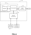
- FIG. 2 illustrates a more detailed block diagram of the charge controller 130 of the charger 20 according to an example embodiment.
- the charge controller 130 may include processing circuitry 210 of an example embodiment as described herein.
- the charge controller 130 may utilize the processing circuitry 210 to provide electronic control inputs to one or more functional units of the charger 20 and/or the first and second battery packs 30 and 32 (e.g., the control circuitry 100/102 and/or the switching assembly 110/112) and to process data generated by the one or more functional units regarding various operational parameters relating to the charger 20 and/or the first and second battery packs 30 and 32.
- the processing circuitry 210 may be configured to perform control function execution and/or other processing and management services according to an example embodiment of the present invention.
- the processing circuitry 210 may be embodied as a chip or chip set.
- the processing circuitry 210 may comprise one or more physical packages (e.g., chips) including materials, components and/or wires on a structural assembly (e.g., a baseboard).
- the structural assembly may provide physical strength, conservation of size, and/or limitation of electrical interaction for component circuitry included thereon.
- the processing circuitry 210 may therefore, in some cases, be configured to implement an embodiment of the present invention on a single chip or as a single "system on a chip.”
- a chip or chipset may constitute means for performing one or more operations for providing the functionalities described herein.
- the processing circuitry 210 may include one or more instances of a processor 212 and memory 214 that may be in communication with or otherwise control a device interface 220 and, in some cases, a user interface 230.
- the processing circuitry 210 may be embodied as a circuit chip (e.g., an integrated circuit chip) configured (e.g., with hardware, software or a combination of hardware and software) to perform operations described herein.
- the processing circuitry 210 may be embodied as a portion of an on-board computer.
- the processing circuitry 210 may communicate with electronic components and/or sensors of a sensor network 240 (e.g., sensors that measure parameters of the charger 20, charger adapter 22 and/or the first and second battery packs 30 and 32) via the device interface 220.
- a sensor network 240 e.g., sensors that measure parameters of the charger 20, charger adapter 22 and/or the first and second battery packs 30 and 32
- part of the sensor network 240, or at least a component or assembly of components with which the processing circuitry 210 may communicate may include any or all of temperature sensors, current sensors, voltage sensors and/or the like.
- the sensor network 240 may be configured to provide indications of parameters of the first and second battery packs 30 and 32 to the charge controller 130 to enable the charge controller 130 to provide instructions or commands to the control circuitry 100/102 for operation of the switch assemblies 110/112 based on data provided via the data and power interface buses 144 and 154.
- the user interface 230 may be in communication with the processing circuitry 210 to receive an indication of a user input at the user interface 230 and/or to provide an audible, visual, tactile or other output to the user.
- the user interface 130 may include, for example, a display, one or more levers, switches, buttons or keys (e.g., function buttons), and/or other input/output mechanisms.
- the user interface 230 may be used by the operator to define settings, operational modes or other criteria to impact operation of the charge controller 130 or components operably coupled thereto.
- the device interface 220 may include one or more interface mechanisms for enabling communication with other devices (e.g., sensors of the sensor network 240 or other functional units or power equipment in connection with which an example embodiment may be employed).
- the device interface 220 may be any means such as a device or circuitry embodied in either hardware, or a combination of hardware and software that is configured to receive and/or transmit data from/to sensors in communication with the processing circuitry 210.
- the processor 212 may be embodied in a number of different ways.
- the processor 212 may be embodied as various processing means such as one or more of a microprocessor or other processing element, a coprocessor, a controller or various other computing or processing devices including integrated circuits such as, for example, an ASIC (application specific integrated circuit), an FPGA (field programmable gate array), or the like.
- the processor 212 may be configured to execute instructions stored in the memory 214 or otherwise accessible to the processor 212.
- the processor 212 may represent an entity (e.g., physically embodied in circuitry - in the form of processing circuitry 210) capable of performing operations according to embodiments of the present invention while configured accordingly.
- the processor 212 when the processor 212 is embodied as an ASIC, FPGA or the like, the processor 212 may be specifically configured hardware for conducting the operations described herein.
- the processor 212 when the processor 212 is embodied as an executor of software instructions, the instructions may specifically configure the processor 212 to perform the operations described herein.
- the processor 212 may be embodied as, include or otherwise control the operation of the charge controller 130 based on inputs received by the processing circuitry 210 responsive to operation of the charger 20 and/or the operation of various ones of any functional units that may be associated with the system 10.
- the processor 212 may be said to cause each of the operations described in connection with the charge controller 130 in relation to operation the charge controller 130 relative to undertaking the corresponding functionalities associated therewith responsive to execution of instructions or algorithms configuring the processor 212 (or processing circuitry 210) accordingly.
- the memory 214 may include one or more non-transitory memory devices such as, for example, volatile and/or non-volatile memory that may be either fixed or removable.
- the memory 214 may be configured to store information, data, applications, instructions or the like for enabling the processing circuitry 210 to carry out various functions in accordance with exemplary embodiments of the present invention.
- the memory 214 could be configured to buffer input data for processing by the processor 212.
- the memory 214 could be configured to store instructions for execution by the processor 212.
- the memory 214 may include one or more databases that may store a variety of data sets responsive to input from the sensor network 240 or any other functional units that may be associated with the system 10.
- applications may be stored for execution by the processor 212 in order to carry out the functionality associated with each respective application.
- the applications may include instructions for recognition of various input conditions related to charge/discharge of the first and second battery packs 30 and 32 and then providing instructions for control of the switch assemblies 110/112 as described herein.
- the charge controller 130 may direct operation of the switch assemblies 110/112 in order to direct sequential or simultaneous charging of multiple battery packs that may be connected to the charger directly or indirectly via charger adapters.
- FIG. 3A illustrates a more detailed block diagram of the control circuitry 100/102 of the first and second battery packs 30 and 32 according to an example embodiment.
- the control circuitry 100/102 may include processing circuitry 310 of an example embodiment as described herein.
- the control circuitry 100/102 may utilize the processing circuitry 310 to provide electronic control inputs to one or more functional units of the first and second battery packs 30 and 32, to respond to instructions from the charge controller 130 and/or to process data generated by the one or more functional units regarding various operational parameters relating to the first and second battery packs 30 and 32, respectively.
- the processing circuitry 310 may be configured to perform control function execution and/or other processing and management services according to an example embodiment of the present invention including providing instructions for operation of the switch assemblies 110/112.
- the processing circuitry 310 may be embodied as a chip or chip set.
- the processing circuitry 310 may comprise one or more physical packages (e.g., chips) including materials, components and/or wires on a structural assembly (e.g., a baseboard).
- the structural assembly may provide physical strength, conservation of size, and/or limitation of electrical interaction for component circuitry included thereon.
- the processing circuitry 310 may therefore, in some cases, be configured to implement an embodiment of the present invention on a single chip or as a single "system on a chip.”
- a chip or chipset may constitute means for performing one or more operations for providing the functionalities described herein.
- the processing circuitry 310 may include one or more instances of a processor 312 and memory 314 that may be in communication with or otherwise control a device interface 320.
- the processing circuitry 310 may be embodied as a circuit chip (e.g., an integrated circuit chip) configured (e.g., with hardware, software or a combination of hardware and software) to perform operations described herein.
- the processing circuitry 310 may be embodied as a portion of an on-board computer.
- the processor 312, the memory 314 and the device interface 320 may be similar in form and function to the processor 212, the memory 214 and the device interface 220 of FIG. 2 , so a detailed description of these components will not be repeated.
- the processing circuitry 310 may communicate with electronic components and/or sensors of a sensor network 340 (e.g., sensors that measure parameters of the first and second battery packs 30 and 32, which may be the same, different or a portion of sensor network 240) via the device interface 320.
- a sensor network 340 e.g., sensors that measure parameters of the first and second battery packs 30 and 32, which may be the same, different or a portion of sensor network 240
- part of the sensor network 340, or at least a component or assembly of components with which the processing circuitry 310 may communicate may include any or all of temperature sensors, current sensors, voltage sensors and/or the like.
- the processing circuitry 310 may be configured to provide diagnostic functionality that is executable based on the processing of sensor network 340 or other data accessed by the processing circuitry 310.
- the sensor network 340 may be configured to provide indications of parameters of the first and second battery packs 30 and 32 to the control circuitry 100/102 to enable the control circuitry 100/102 to provide instructions or commands to the switch assemblies 110/112.
- the switch assemblies 110/112 may include one or more interface mechanisms for enabling the continuation, performance or stopping of execution of various functionalities based on switch positions of specific functional components or portions of the switch assemblies 110/112.
- the switch assemblies 110/112 of one embodiment may include an end of life circuit 350, a battery release circuit 360, and/or a smart fuse circuit 370.
- Each of the end of life circuit 350, the battery release circuit 360, and the smart fuse circuit 370 may be any means such as a device or circuitry embodied in either hardware, or a combination of hardware and software that is configured to perform switching functions either with actual physical switches that are microprocessor controlled or with software/hardware control functionality that functions similar to a switch to control functionalities as described herein.
- the end of life circuit 350 is used to terminate operability of the battery pack in which it is instantiated responsive to activation of the end of life circuit 350.
- the diagnostic function of the processing circuitry 310 may identify a situation (or have such situation identified for it by the processing circuitry 210 of the charge controller 130) which requires that operation of the battery pack be terminated.
- the end of life circuit 350 may, responsive to actuation thereof by the processing circuitry 310, operate a physical switch or may otherwise adjust an operating state of the battery pack in which it is located to disable the operation of the battery pack.
- the end of life circuit 350 may melt or otherwise open a fuse or link, or actuate a switch to isolate the battery cells of the battery pack from the output terminals of the battery pack (e.g., communications interfaces 140 and 142) by opening contacts proximate to the output terminals or along a length of bus work leading to the output terminals.
- a switch may be activated to open circuit the battery cells proximate to the battery cells themselves.
- a switch position may be shifted to align the battery cells to discharge through a dummy load that may form a portion of the end of life circuit 350.
- the dummy load may employ any desirable size of resistor or resistance network that is deemed appropriate to achieve the discharge characteristics desired.
- activation of the end of life circuit 350 may further cause activation of a status indicator or flag to inform the operator of a status change for the battery (e.g., to a disabled status).
- the status indicator may reside locally at the corresponding battery pack, or may be read out at the user interface 230 of the charger 20.
- the status indicator may inform the operator of the existence of a fault that triggered activation of the end of life circuit 350 or of the fact that the battery pack has reached the end of life.
- the status indicator or other indications or data relating to battery condition may be read out from the processing circuitry 310 of the battery using a diagnostic tool.
- the processing circuitry 310 may be configured to record (e.g., in the memory 314) battery parameters and/or events associated with changes in battery parameters that may be responsible for activation of the end of life circuit 350.
- the battery release circuit 360 may be employed to initiate a microprocessor controlled detachment of the battery pack from the power tool 40 (e.g., an electric release).
- the battery release circuit 360 may include a locking mechanism 380 that is released by microprocessor control when operated by the operator and/or when certain detectable conditions necessitate such release. The battery release circuit 360 may therefore interact with the locking mechanism 380 to release the locking mechanism 380 and, in some cases, eject the battery pack.
- the locking mechanism 380 may include a linear or rotary actuator such as an electric motor (e.g., powered by the battery pack itself), solenoid, or other series of microprocessor controlled mechanical linkages (e.g., spring loaded discharge mechanisms that are prevented from operation by a retaining rod or linkage).
- the locking mechanism 380 may therefore operate to either prevent ejection of the battery pack until the locking mechanism 380 is released (e.g., by activation of the battery release circuit 360) or to cause ejection of the battery pack by physically moving the battery pack out of contact with the tool (or charging device) responsive to operation of the battery release circuit 360.
- FIG. 3B illustrates a more detailed block diagram of a battery release circuit and locking mechanism that may be employed according to an example embodiment.
- the locking mechanism 380 includes a solenoid 381 (or motor) and a locking rod 382 that is biased by a spring 383. Operation of the solenoid 381 responsive to instruction from the battery release circuit 360 may cause the locking rod 382 to be released or engaged. In one embodiment, operation of the solenoid 381 may cause the locking rod 382 to be withdrawn against the bias of the spring 383. Thereafter, when the solenoid 381 is not actuated, the spring 383 may cause the locking rod 382 to be urged toward engagement with the battery pack 385.
- the battery release circuit 360 may operate responsive to operator actuation of a release button 384 disposed on the device being powered (e.g., power tool 385).
- a battery pack release button 386 may be provided on the battery pack 387.
- a battery pack controller 388 may provide a signal to the battery release circuit 360 in the power tool 385 to cause the locking mechanism 380 to operate to release the locking rod 382 from engagement with the battery pack 387.
- An ejection spring 389 may then urge the battery pack 387 out of the reception orifice 390 of the power tool 385. Accordingly, while the release mechanism may reside in the power tool 385, the user interface for actuating the release mechanism could be on the battery pack 387 or on the power tool 385.
- a typical battery pack may be held in place against a biasing force that tends to push the battery pack out of contact with its charging device or power tool.
- the typical battery pack may be held in place by a mechanical release mechanism that may be physically moved by the operator to release a detent or clamping mechanism to allow a spring to separate battery contacts from charging device or power tool contacts.
- this type of mechanical release mechanism may be inadvertently operated by the operator to cause an undesirable (and perhaps uncontrolled) release of the battery pack from a tool that could even be in operation.
- some battery packs may require simultaneous operation of two mechanical release levers or mechanisms. However, even these can be inadvertently operated.
- the battery release circuit 360 may employ electronic (e.g., microprocessor) controlled release so that further functionality may be implemented to prevent inadvertent release.
- the battery release circuit 360 may employ electronic control of the locking mechanism 380 so that certain inadvertent release prevention functions may be employed.
- the battery release circuit 360 may not be enabled while the power tool 40 is operating.
- an electronic interlock may prevent operation to release the locking mechanism 380 unless the power tool 40 is not in operation.
- the battery release circuit 360 may initiate operation of the locking mechanism 380 to cause ejection or disconnection of the battery pack from the power tool 40 if, for example, a fault condition is detected.
- the diagnostic function of the processing circuitry 310 has indications of overheating or overcurrent conditions in the battery pack, the battery release circuit 360 may be actuated to release the locking mechanism 380 so that further operation of the battery pack can be stopped.
- actuation of the battery release circuit 360 may be triggered responsive to overheating of a fuse or link that triggers actuation of the locking mechanism 380 to release the battery pack.
- Tool status may also be a basis upon which the battery is prevented from being removed, or for which removal is facilitated for certain status conditions (e.g., active, inactive, operating, etc.).
- any of a number of other electronic interlocks may also trigger operation of the battery release circuit 360, or prevent operation thereof.
- the interlocks may operate to remove the battery when high temperature or current conditions are sensed.
- interlocks may function to prevent battery removal when the tool is in operation or being held at certain orientations (e.g., at an orientation which could lead to the battery falling).
- the actuation of the locking mechanism 380 may cause a solenoid or motor to move the battery pack so that electrical contacts are broken.
- the electrical contacts may be required to be maintained sufficiently to power the locking mechanism 380 at least until the electrical contact between the power tool 40 and the battery pack is broken.
- the connector powering any motor for pushing the battery pack out of contact with the power tool 40 may actually follow the battery pack during movement until the contact with the power tool 40 is broken after which time the contact between the battery pack and the motor may also break to secure operation of the motor.
- a specific actuation sequence may be required to activate the battery release circuit 360.
- a button may be provided that must be pushed or actuated twice (or some other number of times) in order to activate the battery release circuit 360.
- Feedback may be provided after the first actuation to let the operator know that the next actuation will cause the unlocking mechanism 380 to be operated.
- a single steady push or actuation of a button for actuation may cause triggering of the unlocking mechanism 380.
- the steady push may be held a first period of time to trigger feedback to indicate that further holding a second period of time will cause triggering of the unlocking mechanism 380.
- the feedback may be provided visibly (e.g., via an LED light), audibly (e.g., via one or more beeps or buzzes), or tactilely (e.g., via vibration).
- the smart fuse circuit 370 may be provided to enable protective functions to be performed under microprocessor control (e.g., via the processing circuitry 310).
- the smart fuse circuit 370 may provide a power input/output interface that is controllable externally (e.g., via the control circuitry 100/102 and/or the charger controller 130.
- the power input/output interface of the smart fuse circuit 370 may allow power to enter the smart fuse circuit 370 via the power portion of the data and power interface bus 144. However, power may be selectively output from the smart fuse circuit 370 based on control provided by the processing circuitry 310.
- the smart fuse circuit 370 may include internal (i.e., relating to interconnections between cells in one battery pack) and/or external (i.e., relating to interconnections between battery packs) switches that are actuated to control output power from the smart fuse circuit 370 based on microprocessor control.
- the smart fuse circuit 370 may enable multiple batteries (e.g., the first and second battery packs 30 and 32) to be selectively employed simultaneously (in series or in parallel) or sequentially for discharge or charging operation.
- the control circuitry 100/102 may interface with the power tool 40 to determine tool specifications or identity and the control circuitry 100/102 may adjust the configuration of the smart fuse circuit 370 to arrange the first and second battery packs 30 and 32 electrically in a desired manner while both the first and second battery packs 30 and 32 are installed in or otherwise operably coupled to the power tool 40.
- control circuitry 100/102 may interface with the charger 20 (and/or charger adapter 22) to determine and adjust the configuration of the smart fuse circuit 370 to arrange the first and second battery packs 30 and 32 electrically in a desired manner so that the first and second battery packs 30 and 32 can be charged either sequentially or simultaneously.
- the smart fuse circuit 370 may also be configured to operate internal switches to isolate battery cells (or groups of cells) when a respective one of the first and second battery packs 30 and 32 are not in use. Thus, for example, an attempt (inadvertently or otherwise) to short circuit the battery terminals will not short circuit the battery cells.
- the smart fuse circuit 370 may be configured to provide selective switch activation based on battery operational parameters (e.g., voltage, temperature and/or current) to isolate the battery pack, individual cells or groups of cells based on detection of fault conditions.
- battery operational parameters e.g., voltage, temperature and/or current
- the smart fuse circuit 370 may provide a microprocessor controlled protective function such that functions typically performed by fuses prefabricated to melt or otherwise open at specific values can instead be replaced with switches programmed to operate at specific values.
- the values may therefore be adjustable based on operator selection of desired protection values (e.g., via the user interface 230).
- the programming of switch values may be performable either at one specific time or at any desirable time over the life of the battery packs. In some cases, measureable conditions or operating status information may automatically trigger shifts in smart fuse switch activation values.
- the switches when the power tool 40 is operating in a normal discharge mode, the switches may be activated at a first set of values, but if the power tool 40 is operating in a high discharge mode, the activation values may be increased for the smart fuse circuit 370. In some cases, different values may also be assigned for charging operations. Accordingly, in some cases, the control circuitry 100/102 may receive information from the power tool 40 or from the charger 20 to indicate the specific activation values to employ based on the current discharge or charge related mode of operation of the power tool 40 or the charger 20.
- the smart fuse circuit 370 may be further configured to prevent provision of power to the power tool 40 or prevent charging from the charger 20 in situations where either the power tool 40 or the charger 20 is not an approved or proper device for interaction with the first or second battery pack 30 or 32.
- the smart fuse circuit 370 can be used to initiate battery pack segmentation to effectively reduce the classification of the battery.
- the smart fuse circuit 370 may isolate specific groups of cells to reduce the overall size of the battery to instead effectively create several smaller sized batteries (e.g., less than 100 Wh). This segmentation may reduce battery control requirements for transport of the battery pack.
- the smart fuse circuit 370 may enhance product safety by causing isolation of one or more portions of the battery pack, or the entirety of the battery pack, on the basis of the position of various switches, interlocks or other components of the device powered.
- the smart fuse circuit 370 may be controlled based on trigger switch input or any of a number of other switch positions.
- inadvertent or erroneous operation of certain electronic modules and/or product components such as the trigger switch or other switches may also trigger smart fuse circuit 370 operation to isolate at least some portion of the battery pack.
- monitoring of conditions related to electronic functions and/or the position of switches may be used to initiate smart fuse circuit 370 operation.
- the processing circuitry 310 of the battery packs may be employed to provide microprocessor control of charging operations and/or discharging operations via selective activation of the switches of the switch assemblies 110/112 as described above.
- Programmable or otherwise intelligent protective functions, end of life handling, transport preparation, and controlled battery ejection, all under microprocessor control, may also or alternatively be provided.
- some embodiments may further employ the processing circuitry 310 for intelligent charging operation.
- some embodiments may employ specific charging operational sequences based on parameters that can be measured by sensors.
- a two phase charge process may be initiated by the processing circuitry 310 via control of the power application provided to the battery cells. In the first phase, a constant current may be provided until a specific voltage level is achieved.
- the second phase may include the application of a constant voltage for a period of time until full charge is achieved.
- the battery itself may therefore be allowed to set charging levels and/or sequences with the introduction of voltage regulation capabilities within the sensor network or control circuitry of the battery pack.
- the battery chemistry of the battery pack may determine the specific sequences and/or values that are applicable for any given operation.
- FIG. 4A illustrates one example embodiment of a charger assembly 400 including a battery pack 410 having a cover top 412.
- the charger assembly 400 also includes a charger 420 that may be employed in connection with an example embodiment.
- the charger 420 may include a charger base 422 that may sit on a flat surface so that one longitudinal end of the battery pack 410 (i.e., the end opposite of the cover top 412) may be inserted into a charger cradle 430 of the charger 420.
- the charger base 422 may house the charge controller (e.g., charge controller 130 and/or the power section 120).
- a fan or other cooling components may be provided in the charger base 422 to push air upward around the sides of the battery pack 410.
- the battery pack 410 may be enabled to be provided into a cavity of a power tool so that the end opposite the cover top 412, which may include the electrical contacts for charge/discharge, is inserted first and the cover top 412 remains exposed.
- the cover top 412 may include an umbrella-like extension portion 440 that extends around the periphery of the cover top 412 to extend over edges of a battery reception cavity 442 in the power tool 444.
- FIG. 4B illustrates a conceptual side view an example of a battery pack 410' employing the extension portion 440 according to an example embodiment.
- the extension portion 440 may include a seal or gasket 450 that fits between the cover top 412 extension portion and the surface of the power tool to provide waterproofing or for the exclusion of dust and debris from the cavity.
- the extension portion 440 may be a continuous and rigid surface that extends around the battery pack 410 top to engage a seal or gasket 450 that is provided around the battery compartment or battery reception cavity 442 of the device that is powered (e.g., the power tool 444).
- the electronics (e.g., the charge controller 130 and/or the power section 120) of the charger 420 may be in a converter box that may be provided in a cord unit that plugs into the mains power source.
- the charger base 422 and the body of the charger 420 that is shown in FIG. 4 may instead simply provide a charger adapter.
- One or more such charger adapters may then be added in series to connect to each other.
- the charge controller 130 may then direct either series or simultaneous charging of the battery packs.
- FIG. 5 illustrates charger electronics in a converter box 500 and a series of charger adapters (e.g., first charger adapter 510, second charger adapter 520 and third charger adapter 530) connected to each other via bus connections.
- Each charger adapter also includes its own respective battery pack (e.g., first battery pack 540, second battery pack 550 and third battery pack 560) being capable of being charged in accordance with example embodiments.
- charging may alternatively be conducted directly while the battery pack is disposed within the power tool that is powered.
- the power tool may have a charging connection that enables charging to occur while the battery pack is installed within the power tool.
- the power tool (with or without a backpack) may accommodate multiple battery packs that may be charged and/or discharged selectively in parallel or in series.
- the power tool may fit within a wall mount device that may be coupled to a charger.
- the power tool may sit in the wall mount and connect to the charger contacts provided in or on the wall mount.
- the use of a relatively standard battery pack in many different devices with the ability to add additional packs suited to different needs may also enable relatively easy redesign of internal battery pack design features, while maintaining a consistent or standard interface to other devices.
- Multiple battery charger racks may also relatively easily be employed to charge a plurality of batteries simultaneously, or in series according to switch positions controlled by example embodiments.
- FIG. 6 which includes FIGS. 6A and 6B , illustrates a top perspective view of a power tool 600 having a battery pack 610 fully inserted ( FIG. 6B ) and partially inserted ( FIG. 6A ) into a receiving cavity of the power tool 600 according to an example embodiment.
- the battery pack 610 may be moved to the position shown in FIG. 6 by operation of an electric motor that moves the battery pack 610 from the fully seated position (in which the battery pack 610 powers the power tool 600) to the position shown in FIG. 6 where the electrical connection is broken between the power tool 600 and the battery pack 610.
- the battery charging system may include one or more battery packs each of which includes control circuitry and a switching assembly, and a charger including a power section and a charge controller.
- the control circuitry is configured to direct operation of the switching assembly to control charging of the one or more battery packs.
- the battery charging system may include additional features that may be optionally added.
- the switching assembly may have programmable switch actuation values.
- the charger may be configured to charge the one or more battery packs either sequentially or simultaneously dependent upon settings of the switching assembly as provided by the charge controller and/or the control circuitry.
- the one or more battery packs may each include an end of life circuit to enable cells of the battery pack to be discharged responsive to positioning of the switching assembly.
- the one or more battery packs may each include a smart fuse circuit to enable isolation of one or more cells of the one or more battery packs.
- the smart fuse circuit is activated on the basis of parameters of the one or more battery packs or on the basis of a position of one or more switches and/or monitoring conditions of a device powered by the one or more battery packs.
- any or all of (1) to (5) may be employed, and the one or more battery packs may each include an end of life circuit to enable cells of the battery pack to be discharged. In some embodiments, any or all of (1) to (5) may be employed, and the one or more battery packs may each include a battery release circuit to enable a locking mechanism holding the one or more battery packs to respective power tools to be released under control of the control circuitry. In some embodiments, any or all of (1) to (5) may be employed, and the one or more battery packs may each include a battery release circuit to provide powered movement of a battery pack out of electrical contact with a power tool with which the battery pack is operably coupled.
- any or all of (1) to (5) may be employed, and the one or more battery packs may each include a smart fuse circuit to enable sequential or simultaneous discharge of multiple ones of the battery packs within a single power tool.
- any or all of (1) to (5) may be employed, and the system may further include a sensor network configured to measure battery operational parameters, wherein the one or more battery packs each include a smart fuse circuit to enable isolation of the one or more battery packs via the switch assembly based on the operational parameters.
- any or all of (1) to (5) may be employed, and the one or more battery packs may include an umbrella-like extension portion that extends around a periphery of one longitudinal end cap of the one or more battery packs, the extension portion extending over edges of a battery pack reception cavity of a device powered by the one or more battery packs.
- the device may include a gasket disposed around a reception cavity to interface with the extension portion to seal the reception cavity when the one or more battery packs are installed in the device.
Landscapes
- Engineering & Computer Science (AREA)
- Chemical & Material Sciences (AREA)
- Chemical Kinetics & Catalysis (AREA)
- Electrochemistry (AREA)
- General Chemical & Material Sciences (AREA)
- Manufacturing & Machinery (AREA)
- Microelectronics & Electronic Packaging (AREA)
- Charge And Discharge Circuits For Batteries Or The Like (AREA)
- Secondary Cells (AREA)
- Power Engineering (AREA)
Claims (19)
- Batterieladesystem, das Folgendes umfasst:ein oder mehrere Batteriepacks (30; 32), von denen jedes eine Steuerschaltung (100; 102) und eine Schaltanordnung (110; 112) enthält; undein Ladegerät (20) mit einem Leistungsabschnitt (120) und einem Laderegler (110),wobei die Steuerschaltung (100; 102) so konfiguriert ist, dass sie den Betrieb der Schaltanordnung (110; 112) steuert, um das Laden des einen oder der mehreren Batteriepacks (30; 32) zu steuern, und wobei das eine oder die mehreren Batteriepacks (30; 32) jeweils eine End-of-Life-Schaltung (350) enthalten, die so konfiguriert ist, dass sie als Reaktion auf ihre Betätigung durch die Steuerschaltung (100; 102) die Funktionsfähigkeit des Batteriepacks (30; 32) beendet, indem sie eine Verbindung öffnet, um die Batteriezellen des Batteriepacks (30; 32) von den Ausgangsanschlüssen des Batteriepacks (30; 32) zu isolieren.
- Batterieladesystem nach Anspruch 1, wobei die Schaltanordnung programmierbare Schalterbetätigungswerte aufweist.
- Batterieladesystem nach Anspruch 1, wobei die End-of-Life-Schaltungen (350) so konfiguriert sind, dass sie das Entladen der Zellen des jeweiligen Batteriepacks (30; 32) in Abhängigkeit von der Positionierung der Schaltanordnung (110; 112) ermöglichen.
- Batterieladesystem nach Anspruch 1, wobei das eine oder die mehreren Batteriepacks jeweils eine intelligente Sicherungsschaltung enthalten, um die Isolierung einer oder mehrerer Zellen des einen oder der mehreren Batteriepacks zu ermöglichen.
- Batterieladesystem nach Anspruch 4, wobei die intelligente Sicherungsschaltung auf der Grundlage von Parametern des einen oder der mehreren Batteriepacks oder auf der Grundlage einer Position eines oder mehrerer Schalter und/oder Überwachungsbedingungen eines von dem einen oder den mehreren Batteriepacks gespeisten Gerätes aktiviert wird.
- Batterieladesystem nach einem der Ansprüche 1-2, wobei die End-of-Life-Schaltungen (350) so konfiguriert sind, dass die Zellen des jeweiligen Batteriepacks (30; 32) entladen werden können.
- Batterieladesystem nach einem der Ansprüche 1-5, wobei das eine oder die mehreren Batteriepacks jeweils eine Batteriefreigabeschaltung enthalten, die es ermöglicht, dass ein Verriegelungsmechanismus, der das eine oder die mehreren Batteriepacks an den jeweiligen Elektrowerkzeugen hält, unter Kontrolle der Steuerschaltung freigegeben wird.
- Batterieladesystem nach einem der Ansprüche 1-3, das ferner ein Sensornetzwerk umfasst, das so konfiguriert ist, dass es die Betriebsparameter der Batterie misst, und wobei das eine oder die mehreren Batteriepacks jeweils eine intelligente Sicherungsschaltung umfassen, um die Isolierung des einen oder der mehreren Batteriepacks über die Schalteranordnung auf der Grundlage der Betriebsparameter zu ermöglichen.
- Batterieladesystem nach einem der Ansprüche 1-5, wobei das eine oder die mehreren Batteriepacks einen schirmartigen Verlängerungsabschnitt aufweisen, der sich um den Umfang einer Längsendkappe des einen oder der mehreren Batteriepacks erstreckt, wobei sich der Verlängerungsabschnitt über die Kanten eines Batteriepack-Aufnahmehohlraums eines Gerätes erstreckt, das von dem einen oder den mehreren Batteriepacks gespeist wird.
- Batterieladesystem nach Anspruch 9, wobei das Gerät eine Dichtung enthält, die um einen Aufnahmehohlraum herum angeordnet ist, um mit dem Verlängerungsabschnitt zusammenzuwirken, um den Aufnahmehohlraum abzudichten, wenn das eine oder die mehreren Batteriepacks in dem Gerät installiert sind.
- Batteriepack für ein Batterieladesystem, wobei das Batteriepack (30) Folgendes umfasst:Steuerschaltung (100); undeine Schaltanordnung (110), die so konfiguriert ist, dass sie eine Schnittstelle zwischen den Zellen des Batteriepacks (30) und einem Leistungsabschnitt (120) des Ladegerätes (20) bildet,wobei die Steuerschaltung (100) so konfiguriert ist, dass sie den Betrieb der Schaltanordnung (110) steuert, um das Laden der Zellen des Batteriepacks (30) zu steuern, und wobei das Batteriepack (30) eine End-of-Life-Schaltung (350) enthält, die so konfiguriert ist, dass sie in Reaktion auf ihre Betätigung durch die Steuerschaltung (100) die Funktionsfähigkeit des Batteriepacks (30) beendet, indem sie eine Verbindung öffnet, um die Batteriezellen des Batteriepacks (30) von den Ausgangsanschlüssen des Batteriepacks (30) zu isolieren.
- Batteriepack nach Anspruch 11, wobei die Schaltanordnung programmierbare Schalterbetätigungswerte aufweist.
- Batteriepack nach Anspruch 11, wobei die End-of-Life-Schaltung (350) so konfiguriert ist, dass die Zellen des Batteriepacks (30) in Reaktion auf die Positionierung der Schaltanordnung (110) entladen werden können.
- Batteriepack nach Anspruch 11, wobei das Batteriepack eine intelligente Sicherungsschaltung enthält, um die Isolierung einer oder mehrerer Zellen des Batteriepacks zu ermöglichen.
- Batteriepack nach Anspruch 14, wobei die intelligente Sicherungsschaltung auf der Grundlage von Parametern des Batteriepacks oder auf der Grundlage einer Position eines oder mehrerer Schalter und/oder Überwachungsbedingungen eines von dem Batteriepack gespeisten Gerätes aktiviert wird.
- Batteriepack nach einem der Ansprüche 11-15, wobei das Batteriepack eine Batteriefreigabeschaltung enthält, die es ermöglicht, dass ein Verriegelungsmechanismus, der das Batteriepack an einem entsprechenden Elektrowerkzeug hält, unter Kontrolle der Steuerschaltung freigegeben wird.
- Batteriepack nach einem der Ansprüche 11-13, wobei das Batteriepack in betriebsfähiger Kommunikation mit einem Sensornetzwerk steht, das so konfiguriert ist, dass es die Betriebsparameter der Batterie misst, und wobei das Batteriepack eine intelligente Sicherungsschaltung enthält, um die Isolierung des Batteriepacks über die Schalteranordnung auf der Grundlage der vom Sensornetzwerk gemessenen Betriebsparameter zu ermöglichen.
- Batteriepack nach einem der Ansprüche 11-15, wobei das Batteriepack einen schirmartigen Verlängerungsabschnitt aufweist, der sich um einen Umfang einer Längsendkappe des Batteriepacks erstreckt, wobei sich der Verlängerungsabschnitt über die Ränder eines Batteriepack-Aufnahmehohlraums eines durch das Batteriepack gespeisten Gerätes erstreckt.
- Batteriepack nach Anspruch 18, wobei das Gerät eine Dichtung enthält, die um den Aufnahmehohlraum herum angeordnet ist, um mit dem Verlängerungsabschnitt zusammenzuwirken, um den Aufnahmehohlraum abzudichten, wenn das Batteriepack in dem Gerät installiert ist.
Applications Claiming Priority (2)
| Application Number | Priority Date | Filing Date | Title |
|---|---|---|---|
| US201361759515P | 2013-02-01 | 2013-02-01 | |
| PCT/US2014/013832 WO2014120912A1 (en) | 2013-02-01 | 2014-01-30 | Battery pack interface system |
Publications (3)
| Publication Number | Publication Date |
|---|---|
| EP2951879A1 EP2951879A1 (de) | 2015-12-09 |
| EP2951879A4 EP2951879A4 (de) | 2016-08-31 |
| EP2951879B1 true EP2951879B1 (de) | 2023-05-10 |
Family
ID=51262936
Family Applications (1)
| Application Number | Title | Priority Date | Filing Date |
|---|---|---|---|
| EP14746203.0A Active EP2951879B1 (de) | 2013-02-01 | 2014-01-30 | Batteriepack-schnittstellensystem |
Country Status (4)
| Country | Link |
|---|---|
| US (1) | US10211488B2 (de) |
| EP (1) | EP2951879B1 (de) |
| CN (1) | CN105103365B (de) |
| WO (1) | WO2014120912A1 (de) |
Families Citing this family (41)
| Publication number | Priority date | Publication date | Assignee | Title |
|---|---|---|---|---|
| US20150137759A1 (en) * | 2013-08-22 | 2015-05-21 | MobileQubes, LLC | Automated Mobile Device Battery Charging Kiosks |
| US10826313B2 (en) * | 2014-02-28 | 2020-11-03 | Apple Inc. | Power management systems for product demonstration fixtures |
| US9583803B2 (en) * | 2014-06-11 | 2017-02-28 | Enovate Medical Llc | Shielding receptable for battery cells |
| EP3068010A1 (de) * | 2015-03-10 | 2016-09-14 | HILTI Aktiengesellschaft | Netzbetreibbares Akku-Ladegerät und Ladesystem |
| WO2017013602A1 (en) * | 2015-07-21 | 2017-01-26 | Husqvarna Ab | Lawn care vehicle with on board battery charging |
| CN107294145A (zh) * | 2016-03-30 | 2017-10-24 | 通用电气公司 | 充电装置、系统和方法 |
| CN213185534U (zh) * | 2016-05-25 | 2021-05-11 | 米沃奇电动工具公司 | 电力设备 |
| EP4475269A3 (de) * | 2016-08-10 | 2025-03-19 | Briggs & Stratton, LLC | Benutzerskalierbare antriebseinheit mit abnehmbaren batteriepacks |
| CN107846046A (zh) * | 2016-09-18 | 2018-03-27 | 苏州宝时得电动工具有限公司 | 充电方法、充电装置及充电系统 |
| ES2729346T3 (es) | 2016-12-16 | 2019-10-31 | Defond Electech Co Ltd | Un método y un sistema para su uso en la conexión operativa de un paquete de baterías a una máquina |
| US11431224B2 (en) | 2017-02-15 | 2022-08-30 | Black & Decker Inc. | Power and home tools |
| CN107221976B (zh) * | 2017-06-11 | 2020-06-23 | 珠海智融科技有限公司 | 一种移动电源 |
| CN116191610A (zh) | 2017-06-26 | 2023-05-30 | 豪倍公司 | 分布式充电站 |
| JP6323822B1 (ja) * | 2017-07-07 | 2018-05-16 | Mirai−Labo株式会社 | 電源装置および電源制御方法 |
| US11380320B2 (en) * | 2017-09-25 | 2022-07-05 | Positec Power Tools (Suzhou) Co., Ltd. | Electric tool system, charger, electric tool, and voice control method thereof, automatic working system, charging station, self-moving device, and voice control method thereof |
| DE102017124153B4 (de) | 2017-10-17 | 2019-07-18 | Einhell Germany Ag | Verfahren und System zum Betreiben von mehreren in einem Elektrogerät eingesetzten Akkupacks |
| WO2019169109A1 (en) * | 2018-02-28 | 2019-09-06 | Hubbell Incorporated | Distributed charging station |
| EP3787920A4 (de) * | 2018-05-04 | 2022-01-12 | Briggs & Stratton, LLC | Modulare batterieanordnung für batteriebetriebene geräte |
| US11817731B2 (en) | 2018-10-12 | 2023-11-14 | Briggs & Stratton, Llc | Battery assembly for battery powered equipment |
| WO2020172845A1 (en) * | 2019-02-27 | 2020-09-03 | Gp Batteries International Limited | A device for managing rechargeable batteries and a battery charging system comprising said device |
| JP7337961B2 (ja) | 2019-06-05 | 2023-09-04 | エーヴィーエル パワートレイン エンジニアリング インコーポレイテッド | 車両フレーム組立体と電源トレイ |
| WO2020247704A1 (en) * | 2019-06-05 | 2020-12-10 | Avl Powertrain Engineering, Inc. | Vehicle frame and power supply assembly and related systems and methods |
| CN114080740B (zh) | 2019-07-19 | 2025-01-03 | 米沃奇电动工具公司 | 用于高功率装置的可重置电子熔断器 |
| US11843097B2 (en) * | 2019-09-10 | 2023-12-12 | Avl Powertrain Engineering, Inc. | Power supply control systems and methods |
| CN114586255A (zh) * | 2019-10-15 | 2022-06-03 | 华为技术有限公司 | 用于优化充电和冷使用的多个电池 |
| CN111682615A (zh) * | 2020-06-18 | 2020-09-18 | 格力博(江苏)股份有限公司 | 充电控制电路、充电装置及充电系统 |
| JP7593711B2 (ja) * | 2020-06-25 | 2024-12-03 | ミルウォーキー エレクトリック ツール コーポレイション | マルチベイ電源の充電均衡 |
| WO2022008332A1 (en) * | 2020-07-06 | 2022-01-13 | Husqvarna Ab | Energy transfer device |
| US20230420959A1 (en) * | 2020-11-18 | 2023-12-28 | Cochlear Limited | Implantable battery disconnection |
| EP4009478B1 (de) * | 2020-12-03 | 2025-01-01 | Metabowerke GmbH | Konfigurierbares akkupack, akkubetriebenes gerät, externes ladegerät und verfahren zur konfiguration eines akkupacks |
| CN112671062B (zh) * | 2020-12-17 | 2025-06-13 | 维沃移动通信有限公司 | 充电控制方法及装置 |
| EP4302381A4 (de) | 2021-03-05 | 2025-07-23 | Milwaukee Electric Tool Corp | Akkuladegerät für elektrowerkzeug |
| DE202023103553U1 (de) * | 2022-06-27 | 2023-09-18 | Milwaukee Electric Tool Corporation | Vorrichtung mit einer Sicherung |
| DE102022134904A1 (de) * | 2022-12-28 | 2024-07-04 | Pfanner Schutzbekleidung Gmbh | Powerbankmodul, Powerbank und Verfahren zum Betreiben eines Powerbankmoduls |
| US12170360B2 (en) | 2023-01-20 | 2024-12-17 | Dimaag-Ai, Inc. | Battery modules comprising immersion-cooled prismatic battery cells and methods of fabricating thereof |
| US11784369B1 (en) * | 2023-03-10 | 2023-10-10 | Dimaag-Ai, Inc. | Swappable battery modules comprising immersion-thermally controlled prismatic battery cells and methods of fabricating thereof |
| US12235061B1 (en) | 2023-08-03 | 2025-02-25 | Bae Systems Information And Electronic Systems Integration Inc. | Smart store communication interface (SSCI) compatible squib design |
| US12510336B1 (en) | 2023-08-03 | 2025-12-30 | Bae Systems Information And Electronic Systems Integration Inc. | Squib enabled hold up battery switch |
| US12253342B1 (en) | 2023-08-03 | 2025-03-18 | Bae Systems Information And Electronic Systems Integration Inc. | Impulse cartridge cup for smart stores communication interface squib with electronics |
| US20250094551A1 (en) * | 2023-09-20 | 2025-03-20 | Paired Power, Inc. | Battery security systems and methods |
| EP4681187A1 (de) * | 2023-10-26 | 2026-01-21 | United Rentals, Inc. | Selbstbelüftender bauwerkzeugbehälter und verfahren zur verwendung davon |
Citations (2)
| Publication number | Priority date | Publication date | Assignee | Title |
|---|---|---|---|---|
| US7003679B1 (en) * | 2001-10-12 | 2006-02-21 | Xilinx, Inc. | System and method for storing a charging algorithm and charging methodology associated with a battery and selectively connecting a critical circuit to a battery voltage pin |
| US20120025771A1 (en) * | 2010-07-28 | 2012-02-02 | Apple Inc. | Swelling management in batteries for portable electronic devices |
Family Cites Families (15)
| Publication number | Priority date | Publication date | Assignee | Title |
|---|---|---|---|---|
| JP3069498B2 (ja) | 1994-09-01 | 2000-07-24 | 富士通株式会社 | 充放電装置および電子機器 |
| US5734253A (en) * | 1996-07-26 | 1998-03-31 | Telxon Corporation | Multiple station charging apparatus with stored charging algorithms |
| US5780991A (en) * | 1996-07-26 | 1998-07-14 | Telxon Corporation | Multiple station charging apparatus with single charging power supply for parallel charging |
| US6459175B1 (en) * | 1997-11-17 | 2002-10-01 | Patrick H. Potega | Universal power supply |
| US6420852B1 (en) * | 1998-08-21 | 2002-07-16 | Sony Corporation | Battery pack |
| US6184659B1 (en) * | 1999-02-16 | 2001-02-06 | Microchip Technology Incorporated | Microcontroller with integral switch mode power supply controller |
| JP3765081B2 (ja) * | 2002-04-26 | 2006-04-12 | 株式会社マキタ | バッテリ駆動式電動工具 |
| US7202631B2 (en) * | 2003-06-24 | 2007-04-10 | Dell Products L.P. | Battery and system power selector integration scheme |
| JP2005321983A (ja) * | 2004-05-07 | 2005-11-17 | Sony Corp | 電子機器、バッテリーパック、電子機器の電源制御方法及びそのプログラム |
| US7538519B2 (en) * | 2004-11-24 | 2009-05-26 | Dell Products L.P. | Information handling system with battery protected from non-permanent failures |
| US20090274948A1 (en) * | 2008-05-05 | 2009-11-05 | Calderone Samuel J | Cordless power tool battery pack system |
| US8441230B2 (en) * | 2008-09-08 | 2013-05-14 | Techtronic Power Tools Technology Limited | Battery charger |
| US8054189B2 (en) * | 2008-10-16 | 2011-11-08 | Walter Kidde Portable Equipment Inc. | Life safety device with automatic battery discharge at the end of life |
| JP5208149B2 (ja) * | 2009-04-09 | 2013-06-12 | パナソニック株式会社 | 保護回路、及び電池パック |
| EP2721716B1 (de) | 2011-06-17 | 2017-03-08 | Southwest Electronic Energy Corporation | Modulüberbrückungsschalter zum ausgleichen von batteriesatzsystemmodulen mit bypassstromüberwachung |
-
2014
- 2014-01-30 US US14/763,201 patent/US10211488B2/en active Active
- 2014-01-30 WO PCT/US2014/013832 patent/WO2014120912A1/en not_active Ceased
- 2014-01-30 EP EP14746203.0A patent/EP2951879B1/de active Active
- 2014-01-30 CN CN201480019888.1A patent/CN105103365B/zh not_active Expired - Fee Related
Patent Citations (2)
| Publication number | Priority date | Publication date | Assignee | Title |
|---|---|---|---|---|
| US7003679B1 (en) * | 2001-10-12 | 2006-02-21 | Xilinx, Inc. | System and method for storing a charging algorithm and charging methodology associated with a battery and selectively connecting a critical circuit to a battery voltage pin |
| US20120025771A1 (en) * | 2010-07-28 | 2012-02-02 | Apple Inc. | Swelling management in batteries for portable electronic devices |
Also Published As
| Publication number | Publication date |
|---|---|
| CN105103365B (zh) | 2017-10-31 |
| EP2951879A1 (de) | 2015-12-09 |
| US20150357684A1 (en) | 2015-12-10 |
| EP2951879A4 (de) | 2016-08-31 |
| US10211488B2 (en) | 2019-02-19 |
| WO2014120912A1 (en) | 2014-08-07 |
| CN105103365A (zh) | 2015-11-25 |
Similar Documents
| Publication | Publication Date | Title |
|---|---|---|
| EP2951879B1 (de) | Batteriepack-schnittstellensystem | |
| EP3079182B1 (de) | Batteriepack, ladevorrichtung und elektrowerkzeug | |
| US8733470B2 (en) | Electric machine tool | |
| EP2015421B1 (de) | Rücksetzmechanismus für ein Batteriepaket | |
| JP4011563B2 (ja) | バッテリ保護のための方法およびシステム | |
| US9130383B2 (en) | Charging/discharging control device, battery pack, electrical equipment, and charging/discharging control method | |
| EP2875712B1 (de) | Rasenmäherbatterieanordnung | |
| US20070108944A1 (en) | Power autonomous portable electric tool set | |
| US7498774B2 (en) | Battery pack for hand-held electric machine tools | |
| EP3609048A1 (de) | Batteriepack mit einer batteriepack-blackbox | |
| CN104969408B (zh) | 电池包及电气设备 | |
| US11811250B2 (en) | Removable battery pack and/or electrical consumer with an electromechanical interface for supplying energy | |
| JP4488381B2 (ja) | 電池パックシステム | |
| JP2009142140A (ja) | Memsベースのバッテリ監視 | |
| US20090128093A1 (en) | Accumulator And Combination Of Accumulator With Device | |
| CN115485949A (zh) | 具有数据监控的智能钻孔机和具有数据监控的智能医学电动驱动器械 | |
| CN120188309A (zh) | 电池包和电池插座 | |
| CN108206307A (zh) | 用于将电池组可操作地连接到机器的方法和系统 | |
| CN212461950U (zh) | 手持电动工具及其电池包、充电座 | |
| CN111095719B (zh) | 蓄电池装置 | |
| US20240162723A1 (en) | Control circuit for operating a electrical energy store | |
| CN110768361B (zh) | 电动工具 | |
| CN110445200B (zh) | 多包并联的控制电路、控制方法及电动工具 | |
| JP2013105726A (ja) | 電池パックおよび電池カバー | |
| US20240380228A1 (en) | Interface Module for Operating an Electrical Consumer with at Least One Exchangeable Energy Storage Device and a Method for Controlling the Electrical Consumer by Means of the Interface Module |
Legal Events
| Date | Code | Title | Description |
|---|---|---|---|
| PUAI | Public reference made under article 153(3) epc to a published international application that has entered the european phase |
Free format text: ORIGINAL CODE: 0009012 |
|
| 17P | Request for examination filed |
Effective date: 20150810 |
|
| AK | Designated contracting states |
Kind code of ref document: A1 Designated state(s): AL AT BE BG CH CY CZ DE DK EE ES FI FR GB GR HR HU IE IS IT LI LT LU LV MC MK MT NL NO PL PT RO RS SE SI SK SM TR |
|
| AX | Request for extension of the european patent |
Extension state: BA ME |
|
| DAX | Request for extension of the european patent (deleted) | ||
| A4 | Supplementary search report drawn up and despatched |
Effective date: 20160802 |
|
| RIC1 | Information provided on ipc code assigned before grant |
Ipc: H01M 10/44 20060101AFI20160727BHEP Ipc: H02J 7/00 20060101ALI20160727BHEP |
|
| RAP1 | Party data changed (applicant data changed or rights of an application transferred) |
Owner name: HUSQVARNA AB |
|
| STAA | Information on the status of an ep patent application or granted ep patent |
Free format text: STATUS: EXAMINATION IS IN PROGRESS |
|
| 17Q | First examination report despatched |
Effective date: 20180316 |
|
| GRAP | Despatch of communication of intention to grant a patent |
Free format text: ORIGINAL CODE: EPIDOSNIGR1 |
|
| STAA | Information on the status of an ep patent application or granted ep patent |
Free format text: STATUS: GRANT OF PATENT IS INTENDED |
|
| INTG | Intention to grant announced |
Effective date: 20230207 |
|
| GRAS | Grant fee paid |
Free format text: ORIGINAL CODE: EPIDOSNIGR3 |
|
| GRAA | (expected) grant |
Free format text: ORIGINAL CODE: 0009210 |
|
| STAA | Information on the status of an ep patent application or granted ep patent |
Free format text: STATUS: THE PATENT HAS BEEN GRANTED |
|
| AK | Designated contracting states |
Kind code of ref document: B1 Designated state(s): AL AT BE BG CH CY CZ DE DK EE ES FI FR GB GR HR HU IE IS IT LI LT LU LV MC MK MT NL NO PL PT RO RS SE SI SK SM TR |
|
| REG | Reference to a national code |
Ref country code: GB Ref legal event code: FG4D |
|
| REG | Reference to a national code |
Ref country code: AT Ref legal event code: REF Ref document number: 1567630 Country of ref document: AT Kind code of ref document: T Effective date: 20230515 Ref country code: CH Ref legal event code: EP |
|
| REG | Reference to a national code |
Ref country code: DE Ref legal event code: R096 Ref document number: 602014086898 Country of ref document: DE |
|
| REG | Reference to a national code |
Ref country code: IE Ref legal event code: FG4D |
|
| REG | Reference to a national code |
Ref country code: LT Ref legal event code: MG9D |
|
| REG | Reference to a national code |
Ref country code: NL Ref legal event code: MP Effective date: 20230510 |
|
| REG | Reference to a national code |
Ref country code: AT Ref legal event code: MK05 Ref document number: 1567630 Country of ref document: AT Kind code of ref document: T Effective date: 20230510 |
|
| PG25 | Lapsed in a contracting state [announced via postgrant information from national office to epo] |
Ref country code: SE Free format text: LAPSE BECAUSE OF FAILURE TO SUBMIT A TRANSLATION OF THE DESCRIPTION OR TO PAY THE FEE WITHIN THE PRESCRIBED TIME-LIMIT Effective date: 20230510 Ref country code: PT Free format text: LAPSE BECAUSE OF FAILURE TO SUBMIT A TRANSLATION OF THE DESCRIPTION OR TO PAY THE FEE WITHIN THE PRESCRIBED TIME-LIMIT Effective date: 20230911 Ref country code: NO Free format text: LAPSE BECAUSE OF FAILURE TO SUBMIT A TRANSLATION OF THE DESCRIPTION OR TO PAY THE FEE WITHIN THE PRESCRIBED TIME-LIMIT Effective date: 20230810 Ref country code: NL Free format text: LAPSE BECAUSE OF FAILURE TO SUBMIT A TRANSLATION OF THE DESCRIPTION OR TO PAY THE FEE WITHIN THE PRESCRIBED TIME-LIMIT Effective date: 20230510 Ref country code: ES Free format text: LAPSE BECAUSE OF FAILURE TO SUBMIT A TRANSLATION OF THE DESCRIPTION OR TO PAY THE FEE WITHIN THE PRESCRIBED TIME-LIMIT Effective date: 20230510 Ref country code: AT Free format text: LAPSE BECAUSE OF FAILURE TO SUBMIT A TRANSLATION OF THE DESCRIPTION OR TO PAY THE FEE WITHIN THE PRESCRIBED TIME-LIMIT Effective date: 20230510 |
|
| PG25 | Lapsed in a contracting state [announced via postgrant information from national office to epo] |
Ref country code: RS Free format text: LAPSE BECAUSE OF FAILURE TO SUBMIT A TRANSLATION OF THE DESCRIPTION OR TO PAY THE FEE WITHIN THE PRESCRIBED TIME-LIMIT Effective date: 20230510 Ref country code: PL Free format text: LAPSE BECAUSE OF FAILURE TO SUBMIT A TRANSLATION OF THE DESCRIPTION OR TO PAY THE FEE WITHIN THE PRESCRIBED TIME-LIMIT Effective date: 20230510 Ref country code: LV Free format text: LAPSE BECAUSE OF FAILURE TO SUBMIT A TRANSLATION OF THE DESCRIPTION OR TO PAY THE FEE WITHIN THE PRESCRIBED TIME-LIMIT Effective date: 20230510 Ref country code: LT Free format text: LAPSE BECAUSE OF FAILURE TO SUBMIT A TRANSLATION OF THE DESCRIPTION OR TO PAY THE FEE WITHIN THE PRESCRIBED TIME-LIMIT Effective date: 20230510 Ref country code: IS Free format text: LAPSE BECAUSE OF FAILURE TO SUBMIT A TRANSLATION OF THE DESCRIPTION OR TO PAY THE FEE WITHIN THE PRESCRIBED TIME-LIMIT Effective date: 20230910 Ref country code: HR Free format text: LAPSE BECAUSE OF FAILURE TO SUBMIT A TRANSLATION OF THE DESCRIPTION OR TO PAY THE FEE WITHIN THE PRESCRIBED TIME-LIMIT Effective date: 20230510 Ref country code: GR Free format text: LAPSE BECAUSE OF FAILURE TO SUBMIT A TRANSLATION OF THE DESCRIPTION OR TO PAY THE FEE WITHIN THE PRESCRIBED TIME-LIMIT Effective date: 20230811 |
|
| PG25 | Lapsed in a contracting state [announced via postgrant information from national office to epo] |
Ref country code: FI Free format text: LAPSE BECAUSE OF FAILURE TO SUBMIT A TRANSLATION OF THE DESCRIPTION OR TO PAY THE FEE WITHIN THE PRESCRIBED TIME-LIMIT Effective date: 20230510 |
|
| PG25 | Lapsed in a contracting state [announced via postgrant information from national office to epo] |
Ref country code: SK Free format text: LAPSE BECAUSE OF FAILURE TO SUBMIT A TRANSLATION OF THE DESCRIPTION OR TO PAY THE FEE WITHIN THE PRESCRIBED TIME-LIMIT Effective date: 20230510 |
|
| PG25 | Lapsed in a contracting state [announced via postgrant information from national office to epo] |
Ref country code: SM Free format text: LAPSE BECAUSE OF FAILURE TO SUBMIT A TRANSLATION OF THE DESCRIPTION OR TO PAY THE FEE WITHIN THE PRESCRIBED TIME-LIMIT Effective date: 20230510 Ref country code: SK Free format text: LAPSE BECAUSE OF FAILURE TO SUBMIT A TRANSLATION OF THE DESCRIPTION OR TO PAY THE FEE WITHIN THE PRESCRIBED TIME-LIMIT Effective date: 20230510 Ref country code: RO Free format text: LAPSE BECAUSE OF FAILURE TO SUBMIT A TRANSLATION OF THE DESCRIPTION OR TO PAY THE FEE WITHIN THE PRESCRIBED TIME-LIMIT Effective date: 20230510 Ref country code: EE Free format text: LAPSE BECAUSE OF FAILURE TO SUBMIT A TRANSLATION OF THE DESCRIPTION OR TO PAY THE FEE WITHIN THE PRESCRIBED TIME-LIMIT Effective date: 20230510 Ref country code: DK Free format text: LAPSE BECAUSE OF FAILURE TO SUBMIT A TRANSLATION OF THE DESCRIPTION OR TO PAY THE FEE WITHIN THE PRESCRIBED TIME-LIMIT Effective date: 20230510 Ref country code: CZ Free format text: LAPSE BECAUSE OF FAILURE TO SUBMIT A TRANSLATION OF THE DESCRIPTION OR TO PAY THE FEE WITHIN THE PRESCRIBED TIME-LIMIT Effective date: 20230510 |
|
| REG | Reference to a national code |
Ref country code: DE Ref legal event code: R097 Ref document number: 602014086898 Country of ref document: DE |
|
| PLBE | No opposition filed within time limit |
Free format text: ORIGINAL CODE: 0009261 |
|
| STAA | Information on the status of an ep patent application or granted ep patent |
Free format text: STATUS: NO OPPOSITION FILED WITHIN TIME LIMIT |
|
| 26N | No opposition filed |
Effective date: 20240213 |
|
| PG25 | Lapsed in a contracting state [announced via postgrant information from national office to epo] |
Ref country code: SI Free format text: LAPSE BECAUSE OF FAILURE TO SUBMIT A TRANSLATION OF THE DESCRIPTION OR TO PAY THE FEE WITHIN THE PRESCRIBED TIME-LIMIT Effective date: 20230510 |
|
| PG25 | Lapsed in a contracting state [announced via postgrant information from national office to epo] |
Ref country code: SI Free format text: LAPSE BECAUSE OF FAILURE TO SUBMIT A TRANSLATION OF THE DESCRIPTION OR TO PAY THE FEE WITHIN THE PRESCRIBED TIME-LIMIT Effective date: 20230510 Ref country code: IT Free format text: LAPSE BECAUSE OF FAILURE TO SUBMIT A TRANSLATION OF THE DESCRIPTION OR TO PAY THE FEE WITHIN THE PRESCRIBED TIME-LIMIT Effective date: 20230510 |
|
| PG25 | Lapsed in a contracting state [announced via postgrant information from national office to epo] |
Ref country code: MC Free format text: LAPSE BECAUSE OF FAILURE TO SUBMIT A TRANSLATION OF THE DESCRIPTION OR TO PAY THE FEE WITHIN THE PRESCRIBED TIME-LIMIT Effective date: 20230510 |
|
| PG25 | Lapsed in a contracting state [announced via postgrant information from national office to epo] |
Ref country code: MC Free format text: LAPSE BECAUSE OF FAILURE TO SUBMIT A TRANSLATION OF THE DESCRIPTION OR TO PAY THE FEE WITHIN THE PRESCRIBED TIME-LIMIT Effective date: 20230510 |
|
| REG | Reference to a national code |
Ref country code: CH Ref legal event code: PL |
|
| PG25 | Lapsed in a contracting state [announced via postgrant information from national office to epo] |
Ref country code: LU Free format text: LAPSE BECAUSE OF NON-PAYMENT OF DUE FEES Effective date: 20240130 |
|
| GBPC | Gb: european patent ceased through non-payment of renewal fee |
Effective date: 20240130 |
|
| PG25 | Lapsed in a contracting state [announced via postgrant information from national office to epo] |
Ref country code: LU Free format text: LAPSE BECAUSE OF NON-PAYMENT OF DUE FEES Effective date: 20240130 |
|
| PG25 | Lapsed in a contracting state [announced via postgrant information from national office to epo] |
Ref country code: GB Free format text: LAPSE BECAUSE OF NON-PAYMENT OF DUE FEES Effective date: 20240130 |
|
| PG25 | Lapsed in a contracting state [announced via postgrant information from national office to epo] |
Ref country code: BE Free format text: LAPSE BECAUSE OF NON-PAYMENT OF DUE FEES Effective date: 20240131 |
|
| PG25 | Lapsed in a contracting state [announced via postgrant information from national office to epo] |
Ref country code: FR Free format text: LAPSE BECAUSE OF NON-PAYMENT OF DUE FEES Effective date: 20240131 |
|
| PG25 | Lapsed in a contracting state [announced via postgrant information from national office to epo] |
Ref country code: CH Free format text: LAPSE BECAUSE OF NON-PAYMENT OF DUE FEES Effective date: 20240131 |
|
| PG25 | Lapsed in a contracting state [announced via postgrant information from national office to epo] |
Ref country code: GB Free format text: LAPSE BECAUSE OF NON-PAYMENT OF DUE FEES Effective date: 20240130 Ref country code: FR Free format text: LAPSE BECAUSE OF NON-PAYMENT OF DUE FEES Effective date: 20240131 Ref country code: CH Free format text: LAPSE BECAUSE OF NON-PAYMENT OF DUE FEES Effective date: 20240131 Ref country code: BE Free format text: LAPSE BECAUSE OF NON-PAYMENT OF DUE FEES Effective date: 20240131 |
|
| REG | Reference to a national code |
Ref country code: BE Ref legal event code: MM Effective date: 20240131 |
|
| PG25 | Lapsed in a contracting state [announced via postgrant information from national office to epo] |
Ref country code: BG Free format text: LAPSE BECAUSE OF FAILURE TO SUBMIT A TRANSLATION OF THE DESCRIPTION OR TO PAY THE FEE WITHIN THE PRESCRIBED TIME-LIMIT Effective date: 20230510 |
|
| PG25 | Lapsed in a contracting state [announced via postgrant information from national office to epo] |
Ref country code: BG Free format text: LAPSE BECAUSE OF FAILURE TO SUBMIT A TRANSLATION OF THE DESCRIPTION OR TO PAY THE FEE WITHIN THE PRESCRIBED TIME-LIMIT Effective date: 20230510 |
|
| PG25 | Lapsed in a contracting state [announced via postgrant information from national office to epo] |
Ref country code: IE Free format text: LAPSE BECAUSE OF NON-PAYMENT OF DUE FEES Effective date: 20240130 |
|
| PG25 | Lapsed in a contracting state [announced via postgrant information from national office to epo] |
Ref country code: IE Free format text: LAPSE BECAUSE OF NON-PAYMENT OF DUE FEES Effective date: 20240130 |
|
| PGFP | Annual fee paid to national office [announced via postgrant information from national office to epo] |
Ref country code: DE Payment date: 20241216 Year of fee payment: 12 |
|
| PG25 | Lapsed in a contracting state [announced via postgrant information from national office to epo] |
Ref country code: CY Free format text: LAPSE BECAUSE OF FAILURE TO SUBMIT A TRANSLATION OF THE DESCRIPTION OR TO PAY THE FEE WITHIN THE PRESCRIBED TIME-LIMIT; INVALID AB INITIO Effective date: 20140130 |
|
| PG25 | Lapsed in a contracting state [announced via postgrant information from national office to epo] |
Ref country code: HU Free format text: LAPSE BECAUSE OF FAILURE TO SUBMIT A TRANSLATION OF THE DESCRIPTION OR TO PAY THE FEE WITHIN THE PRESCRIBED TIME-LIMIT; INVALID AB INITIO Effective date: 20140130 |
|
| PG25 | Lapsed in a contracting state [announced via postgrant information from national office to epo] |
Ref country code: TR Free format text: LAPSE BECAUSE OF FAILURE TO SUBMIT A TRANSLATION OF THE DESCRIPTION OR TO PAY THE FEE WITHIN THE PRESCRIBED TIME-LIMIT Effective date: 20230510 |