EP2949908A1 - Procédé de simulation d'un moteur à combustion interne - Google Patents
Procédé de simulation d'un moteur à combustion interne Download PDFInfo
- Publication number
- EP2949908A1 EP2949908A1 EP14170618.4A EP14170618A EP2949908A1 EP 2949908 A1 EP2949908 A1 EP 2949908A1 EP 14170618 A EP14170618 A EP 14170618A EP 2949908 A1 EP2949908 A1 EP 2949908A1
- Authority
- EP
- European Patent Office
- Prior art keywords
- simulation
- cylinders
- cylinder
- engine
- master cylinder
- Prior art date
- Legal status (The legal status is an assumption and is not a legal conclusion. Google has not performed a legal analysis and makes no representation as to the accuracy of the status listed.)
- Granted
Links
Images


Classifications
-
- G—PHYSICS
- G06—COMPUTING; CALCULATING OR COUNTING
- G06F—ELECTRIC DIGITAL DATA PROCESSING
- G06F30/00—Computer-aided design [CAD]
- G06F30/20—Design optimisation, verification or simulation
-
- F—MECHANICAL ENGINEERING; LIGHTING; HEATING; WEAPONS; BLASTING
- F02—COMBUSTION ENGINES; HOT-GAS OR COMBUSTION-PRODUCT ENGINE PLANTS
- F02D—CONTROLLING COMBUSTION ENGINES
- F02D41/00—Electrical control of supply of combustible mixture or its constituents
- F02D41/008—Controlling each cylinder individually
- F02D41/0082—Controlling each cylinder individually per groups or banks
-
- F—MECHANICAL ENGINEERING; LIGHTING; HEATING; WEAPONS; BLASTING
- F02—COMBUSTION ENGINES; HOT-GAS OR COMBUSTION-PRODUCT ENGINE PLANTS
- F02D—CONTROLLING COMBUSTION ENGINES
- F02D41/00—Electrical control of supply of combustible mixture or its constituents
- F02D41/24—Electrical control of supply of combustible mixture or its constituents characterised by the use of digital means
- F02D41/2406—Electrical control of supply of combustible mixture or its constituents characterised by the use of digital means using essentially read only memories
- F02D41/2409—Addressing techniques specially adapted therefor
- F02D41/2412—One-parameter addressing technique
-
- F—MECHANICAL ENGINEERING; LIGHTING; HEATING; WEAPONS; BLASTING
- F02—COMBUSTION ENGINES; HOT-GAS OR COMBUSTION-PRODUCT ENGINE PLANTS
- F02D—CONTROLLING COMBUSTION ENGINES
- F02D41/00—Electrical control of supply of combustible mixture or its constituents
- F02D41/24—Electrical control of supply of combustible mixture or its constituents characterised by the use of digital means
- F02D41/2406—Electrical control of supply of combustible mixture or its constituents characterised by the use of digital means using essentially read only memories
- F02D41/2409—Addressing techniques specially adapted therefor
- F02D41/2416—Interpolation techniques
-
- F—MECHANICAL ENGINEERING; LIGHTING; HEATING; WEAPONS; BLASTING
- F02—COMBUSTION ENGINES; HOT-GAS OR COMBUSTION-PRODUCT ENGINE PLANTS
- F02D—CONTROLLING COMBUSTION ENGINES
- F02D41/00—Electrical control of supply of combustible mixture or its constituents
- F02D41/24—Electrical control of supply of combustible mixture or its constituents characterised by the use of digital means
- F02D41/26—Electrical control of supply of combustible mixture or its constituents characterised by the use of digital means using computer, e.g. microprocessor
-
- G—PHYSICS
- G06—COMPUTING; CALCULATING OR COUNTING
- G06F—ELECTRIC DIGITAL DATA PROCESSING
- G06F30/00—Computer-aided design [CAD]
- G06F30/10—Geometric CAD
- G06F30/17—Mechanical parametric or variational design
-
- F—MECHANICAL ENGINEERING; LIGHTING; HEATING; WEAPONS; BLASTING
- F02—COMBUSTION ENGINES; HOT-GAS OR COMBUSTION-PRODUCT ENGINE PLANTS
- F02D—CONTROLLING COMBUSTION ENGINES
- F02D41/00—Electrical control of supply of combustible mixture or its constituents
- F02D41/02—Circuit arrangements for generating control signals
- F02D41/14—Introducing closed-loop corrections
- F02D41/1401—Introducing closed-loop corrections characterised by the control or regulation method
- F02D2041/1433—Introducing closed-loop corrections characterised by the control or regulation method using a model or simulation of the system
- F02D2041/1437—Simulation
-
- F—MECHANICAL ENGINEERING; LIGHTING; HEATING; WEAPONS; BLASTING
- F02—COMBUSTION ENGINES; HOT-GAS OR COMBUSTION-PRODUCT ENGINE PLANTS
- F02D—CONTROLLING COMBUSTION ENGINES
- F02D35/00—Controlling engines, dependent on conditions exterior or interior to engines, not otherwise provided for
- F02D35/02—Controlling engines, dependent on conditions exterior or interior to engines, not otherwise provided for on interior conditions
- F02D35/023—Controlling engines, dependent on conditions exterior or interior to engines, not otherwise provided for on interior conditions by determining the cylinder pressure
- F02D35/024—Controlling engines, dependent on conditions exterior or interior to engines, not otherwise provided for on interior conditions by determining the cylinder pressure using an estimation
-
- F—MECHANICAL ENGINEERING; LIGHTING; HEATING; WEAPONS; BLASTING
- F02—COMBUSTION ENGINES; HOT-GAS OR COMBUSTION-PRODUCT ENGINE PLANTS
- F02D—CONTROLLING COMBUSTION ENGINES
- F02D35/00—Controlling engines, dependent on conditions exterior or interior to engines, not otherwise provided for
- F02D35/02—Controlling engines, dependent on conditions exterior or interior to engines, not otherwise provided for on interior conditions
- F02D35/025—Controlling engines, dependent on conditions exterior or interior to engines, not otherwise provided for on interior conditions by determining temperatures inside the cylinder, e.g. combustion temperatures
- F02D35/026—Controlling engines, dependent on conditions exterior or interior to engines, not otherwise provided for on interior conditions by determining temperatures inside the cylinder, e.g. combustion temperatures using an estimation
Definitions
- the present invention relates to a method for simulation of an internal combustion engine comprising a number of cylinders, wherein simulation output parameters of the cylinders are calculated based on the angular position of a crank shaft. Further the present invention relates to a simulation equipment comprising means to perform the inventive method.
- thermodynamic engine models Due to the complexity of thermodynamic engine models, simulation has to be performed in a computationally efficient manner, even if the most powerful simulation equipment available at this time is being used. Computational efficiency and short computational times are very important in an early development stage as they enable efficient exploration of the vast space of possible solutions, whereas it is of utmost importance during real-time test on hardware-in-the-loop (HiL) simulators. Nonetheless the thermodynamic basis of the model requires solutions of the systems of differential equations in each component introducing a significant computational burden.
- HiL-Simulation refers to a simulation environment, which comprises embedded hardware operating in real-time. To successfully run a HiL-Simulation, not only the simulation part has to be calculated faster than real time, but it also has to be faster in each and every sampling interval throughout the whole HiL-Simulation. This means that, for example, if the data exchange frequency is 1 kHz, each milisecond of the physical time of the model has to be calculated in less than 1 millisecond computational time. Some HiL simulators allow for a limited number of real-time violations, but this does not resolve the underlying problem.
- Simulation tools can be characterized by the respective modeling approach that is used, e.g. simulation tools can be grouped into simulation tools using physical based modeling approaches and simulation tools using data driven modeling approaches.
- data driven modeling approach relates to simulation models that use a fixed input data set for the calculation of simulation parameters. Often measured data and data from previous tests are used and the data can be manipulated by mathematical methods to adapt them to a specific simulation model.
- One particular type of a data driven modeling approach is a map based model wherein model parameters are stored in maps.
- An engine related example for a data set that can be used by a map based modeling approach is the measured fuel consumption as a function of engine speed and torque. During the simulation the model instantaneously returns a value for the fuel consumption as a function of engine speed and required torque by interpolating between the measured/input points.
- neural networks and support and relevance vector machines which are often named “surrogates models” belong to the data driven modeling approaches.
- Some models require “training”, which means that model parameters of, e.g. neural networks and support and relevance vector machines, are adjusted in such a way that the results of the data driven model matches input data as good as possible over the input/trained range of independent variables of the model.
- physical based modeling approach relates to simulation models, wherein processes in the components are modeled based on physical laws, rather than using measured or input data.
- Examples for physical based modeling approaches are dimensional modeling approaches, e.g. the so called 0D modeling approach and 1 D modeling approach.
- Physical based models might also include a limited number of phenomenological sub-models to model specific phenomena that cannot be resolved with physical models.
- thermodynamic equations e.g. equations for mass, energy and optionally species conservation
- a 1 D modeling approach can generally be used to model wave propagation in the intake and exhaust manifolds and elements are therefore discretized in a series of volumes in one dimension.
- momentum equations are solved enabling modeling of pressure wave propagations.
- 2D and 3D modeling approaches can be defined accordingly by adding further dimensions to the simulation model.
- the invention further aims at providing a simulation environment that is capable of performing physical based real time and particularly HiL capable simulations of multi-cylinder engines with complex intake and exhaust system topologies even at a high speed range of the engine.
- EP2579115B1 or US2013090886A1 disclose a method for real time testing of a control unit for an internal combustion engine comprising an engine simulator, wherein at least some of the engine state variables are transmitted to the control unit with a first transmission step size, and at least one specific engine state variable of the engine state variables is transmitted with a second sampling step size that is different from the first sampling step size. It is also possible to ensure timely exchange of the data through the I/O interface by optimizing computational expenses of the model and thus increasing its computational speed.
- WO2008078097A1 discloses a method for creating a simplified computer implementable engine model from a complete computer implementable engine model generated by a 1-dimensional gas dynamics simulation software package. The method at least partially relies on excluding complex elements that are not relevant to flow control model and merging small elements together.
- the present invention addresses these and other problems by providing a method for simulation of an internal combustion engine comprising a number of cylinders, wherein simulation output parameters of the cylinders are calculated based on the angular position of a crank shaft, wherein the method comprises the following steps:
- the method according to this embodiment significantly reduces computational expenses for the simulation of the engine, while it allows for achieving with high accuracy, especially during steady state operation.
- mapping denotes any determination of simulation output parameters for one cylinder (i.e. the slave cylinder), that is done using values that where determined for a different cylinder (i.e. the master cylinder) at a corresponding angular position.
- the intervals of the simulation timesteps are calculated in a time domain and intervals of the crank-angle positions are calculated in an angular domain.
- the steps of the time domain usually correspond to the simulation of the gas path and therefore this domain is also referred to as a "gas path domain".
- the angular domain the angular intervals depend on the angular position of the crank-shaft.
- the duration of one calculation step in the angular domain therefore depends on the rotational speed of the engine and can be significantly shorter than the duration of the simulation timesteps of the time domain.
- Either the length of the time steps and/or the length of the angular intervals can change during the simulation.
- the angular interval could be chosen so that an integer number of angular steps occurs within each time step of the time domain.
- the length of successive angular intervals could also change in a different manner.
- both domains can be calculated in a fully coupled manner using identical time steps in either time or crank-angle intervals.
- mapping can use linear interpolation between previous simulation output parameters stored at an angular interval.
- the invention can additionally comprise the steps of:
- a correction factor can be derived from a simulation or control input parameter, or calculated based on the changes of state variables.
- the correction factor can be derived from simulation or control input parameters, or calculated based on the changes of state variables, which have occurred in the time period that corresponds to the shift in firing angles between the master and slave cylinder, which defines the time delay of that particular slave cylinder.
- This embodiment permits an analytically based computation of correction factors with very low CPU demand. Correction factors can therefore be applied to the simulation output parameters of the slave cylinders to more adequately consider any changes that arise due to transient engine operation. This embodiment therefore combines computational efficiency arising from calculating reduced number of master cylinders and achieving high accuracy of transient results that arises from applying correction factors to the simulation output parameters of the slave cylinders.
- the simulation of the master cylinder can be performed based on a physical based modeling approach.
- the computational expenses of the physical based model depend on the performance of the available simulation equipment and the properties of the simulated engine (e.g.: number of cylinders, number of groups, topology of the intake and exhaust system and topology of turbo/super charging systems and simulated engine speed).
- the number of groups is one. Consequently the simulation only has to simulate thermodynamic equations in a single cylinder for the whole engine, which shortens computational time of the model.
- the number of groups is larger than one. This enables a simulation of an engine in operating conditions, where some of the cylinders are being run with different properties or control strategies than others, e.g. the engine can be simulated with groups of cylinders being deactivated.
- the cylinders could be grouped according to their angular sequence, e.g. into a first group comprising the cylinders that reach the firing top dead center during the first half of the engine cycle, and a second group comprising the cylinders that reach the firing top dead center during the second half of the engine cycle, the master cylinder of the second group being phase delayed to the master cylinder of the first group for half of the engine cycle. This could reduce the effect of the time lag of the slave cylinders.
- the cylinders of at least one group can be associated to a common intake and/or exhaust manifold and/or a common turbo/super charger and/or to a common control strategy.
- a common intake and/or exhaust manifold and/or a common turbo/super charger and/or to a common control strategy can be associated to a common intake and/or exhaust manifold and/or a common turbo/super charger and/or to a common control strategy.
- the simulation equipment according to the present invention can preferably comprise an embedded hardware-unit (HiL-unit), which operates in real time.
- HiL-unit embedded hardware-unit
- the calculations of the simulation with the inventive simulation method can be processed faster compared to a model where thermodynamic equations are calculated in all cylinders. Therefore on a particular HiL hardware a particular engine can be simulated up to higher engine speeds or an engine with more cylinders and/or more complex intake and/or exhaust systems and/or more turbo/super chargers can be simulated, while still complying with constraints imposed by the HiL.
- the simulation equipment can comprise a hardware unit with multiple cores.
- different master cylinders and/or different slave cylinders and/or gas path components can be calculated on separate cores. It is, for example, possible to assign one master cylinder and the respective slave cylinders to a single simulation core (if more than one cylinder groups are defined) and/or to assign gas path components to (a) different core(s).
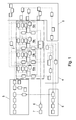
- Fig. 1 and 2 show basic elements of a physically based simulation of a multi-cylinder engine.
- the model presented in Fig. 1 can be grouped to the engine block system 1, a fuel supply system 2, an intake system 3, an exhaust gas system 4, a turbo charger system 5, an engine shaft 6 linked to an exterior mechanical system 7, and a heat transfer model 8.
- the exterior mechanical system 7 can comprise a simulation of further elements of the power train, such as transmission, drive shafts, differentials, and the final drive of a vehicle.
- the domain of the engine block further comprises the corresponding number of cylinders as indicated in Fig. 1 , wherein engine block 1 comprises four single cylinders 10a, 10b, 10c and 10d. Each cylinder comprises a number of simulation elements.
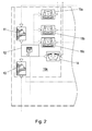
- Fig. 2 shows a more detailed view of the first cylinder 10a of Fig. 1 .
- the simulation elements of cylinder 10a comprise elements for the intake port 11, the combustion chamber 12, the exhaust port 13, the fuel injection 14 and three heat transfer elements 15a, 15b and 15c representing the heat transfer from the combustion chamber to the piston, the liner and the cylinder head, respectively.
- Indicated work given to the pistons of all cylinders is summarized in the mechanical power unit of the engine block 1, where mechanical losses are modeled and thus effective torque is given to the exterior mechanical system.
- the model can be divided into two domains with different characteristic time scales, i.e. the engine block domain, which is characterized by shorter characteristic time scales, and the gas path domain, which is characterized by longer characteristic time scales.
- this domain is denoted as gas path domain as gas components in the gas path are the ones that define the upper level of the applied time steps.
- the gas path domain of Fig. 1 comprises the fuel supply system 2, the intake system 3, the exhaust gas system 4, the turbo charger system 5, the engine shaft 6, the exterior mechanical system 7, and the heat transfer model 8.
- the present invention can be applied to modeling approaches where all domains use the same integration time step or to approaches where the engine block domain uses shorter integration time step than the gas path domain.
- thermodynamic model For reasons of brevity not all systems/elements of the simulation model will be explicitly described in this document, as the structure and operation principle of simulation models are well known to the person skilled in the art, for example from standard simulation tools such as AVL Boost and Cruise, LMS Amesim, a variety of MATLAB Simulink based models or others.
- pressure p, mass m, temperature T and optionally species concentrations w i in the combustion chamber are calculated.
- this calculation gives all the fluxes through the transfer elements attached to the combustion chamber (which are shown in Fig. 2 ).
- the indicated work in the cylinder is calculated by the thermodynamic model.
- the combustion chamber thus exchanges with the intake and exhaust system the mass, enthalpy and optionally species fluxes, through the intake and exhaust ports respectively, with the fuel tank the mass, enthalpy and optionally species fluxes, of the fuel through the fuel injector, with the combustion chamber walls the heat, i.e. enthalpy, fluxes through the heat transfer elements and with the piston the indicated work.
- the present invention is based on a modeling approach wherein one or more master cylinders of multi-cylinder engine are simulated using thermodynamic equations and other slave cylinders and modeled using suitably phased fluxes and indicated work calculated by the corresponding master cylinder.
- master cylinder refers to a cylinder wherein processes in the combustion chamber are simulated using thermodynamic equations.
- slave cylinder refers to a cylinder wherein processes in the combustion chamber are not simulated using thermodynamic equations, therefore fluxes exchanged through the transfer elements attached to the combustion chamber and the indicated work given to the piston are calculated by suitably shifting the phase of these parameters that were calculated by the corresponding master cylinder.
- phase shifting denotes a method of determining simulation parameters of one cylinder (slave cylinder) by using the parameters determined for a different cylinder (master cylinder) at a preceding point of time, and taking into account the angular difference between the master cylinder and the slave cylinder imposed by the firing angles of the cylinders (i.e. the different position of the piston at a given time) as indicated in Fig. 7 and 8 .
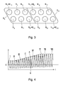
- FIG. 3 shows a schematic representation of cylinders in a multi-cylinder engine.
- Fig. 3 schematically shows the cylinders N 1 -N 12 of a combustion engine comprising 12 cylinders.
- the cylinders are grouped into two cylinder groups G 1 , G 2 , each comprising 6 cylinders M 1,1 -M 1,6 and M 2,1 -M 2,6 , respectively.
- M 1,1 in group G 1 and M 2,1 in group G 2 is defined as a master cylinder.
- the Number of cylinders and groups shown in Fig. 3 is merely an example given to facilitate the understanding of the present specification.
- the grouping of the cylinders according to the invention is not restricted to the shown example. Obviously any different number and grouping of cylinders could be used. In one embodiment all cylinders of an engine belong to a single group.
- the configuration exemplified in Fig. 3 could be used for a simulation of the 12-cylinder engine wherein the cylinders of group G 2 use different properties than the cylinders of group G 1 .
- all cylinders in Group G 2 could be deactivated, i.e. not fired, or could share the same turbo charger and different control strategy, or damage of this turbo charger could be simulated while the function of all other cylinders (in this case all cylinders of group G1) remains unaffected, except over engine dynamics that is influenced by the torque produced by the engine.
- the first group could comprise 9 cylinders and the second group could comprise 3 cylinders.
- Any combination of groups could be used for a simulation model as long as each group at least comprises one cylinder (the master cylinder of this group).
- thermodynamic calculation is used for the simulation according to the invention, pressure p, mass m, temperature t and species concentrations w i in the combustion chamber or in the other parts of the cylinder model ( Fig. 2 ) are only calculated for the master cylinder (in terms of a thermodynamic calculation). In addition this calculation gives all the fluxes through the attached transfer elements. Moreover, indicated work in the cylinder is calculated by the thermodynamic model.
- Data should be written to the flux matrix at least every time step of the gas path domain, which is also the case when time steps of engine block and gas path domain are identical, whereas in the case when the time steps of the engine block domain are shorter than the time steps of the gas path domain the frequency of writing the data can be adjusted between the frequency that correspond to the time steps of the engine block and the frequency corresponding to the time steps of the gas path domain.
- values can be stored if ⁇ stor,n+1 - ⁇ stor,n > ⁇ , where ⁇ is the minimum interval for writing to the flux vector. It is also possible that data are written to the flux matrix at pre-defined values of ⁇ .
- the length of one angular step could depend on more than one condition, e.g. ⁇ stor,n+1 - ⁇ stor,n corresponds to an integer number of angular steps within one time step of the gas path domain, with the prerequisite that ⁇ stor,n+1 - ⁇ stor,n > ⁇ .
- W ind ⁇ 0 ⁇ stor ⁇ p ⁇ dV d ⁇ ⁇ d ⁇ , represents the integrated value of the indicated work from the start of cycle until the actual stored crank-angle ⁇ stor .
- Fig. 7 is a diagram showing the mass flow through the intake port plotted against the crank angle of the respective master cylinder.
- the engine rotates at a speed of 1500 rpm. Therefore the integration time step ⁇ t of the gas path domain of 1 ms corresponds to 9° crank angle and the engine block domain is integrated with steps of 1° crank angle.
- This exemplifies an approach, wherein the integration increments of the gas path domain are decoupled from the integration increments of the engine block domain, and the first one using time increments and the second one using crank-angle increments.
- mass flow through the intake port is integrated for 9° crank angle by the engine block domain and afterwards it is being exchanged with the gas path domain. Thereby it is ensured that consistent fluxes are given to the components of the gas path domain at the time steps of the gas path domain.
- the integrated mass flux thought the intake port of a master cylinder is integrated in the considered time step of the gas path domain from -225° up to - 216° crank angle, where -360° crank angle corresponds to the gas exchange top dead center of the four-stroke engine.
- thermodynamic process are not modeled in the slave cylinders.
- the master cylinder M g,1 the master cylinder M g,1
- this can be done by reading out these values from the "flux matrix” (eq. (1)) and applying them to the slave cylinder (which corresponds to the mapping step).
- crank-angle shifts defined by the firing angle of the slave cylinders have been taken into account, so that every angle referred to in the equations always refers to the respective working cycle position of the cylinder.
- Fig. 8 shows a Diagram which illustrates the writing to the flux matrix and the mapping step for one slave cylinder.
- the second ordinate (II) represents the crank angle position ⁇ m of the master cylinder, wherein the simulation of the master cylinder is calculated at an angular basis (i.e.
- the third ordinate (III) represents the crank angle ⁇ s of a slave cylinder, wherein the crank angle positions of the slave cylinder are offset to the respective cylinder positions of the master cylinder by the angular difference of the respective firing angles ( ⁇ fp ).
- Fig. 8 can be compared to Fig. 7 wherein the ⁇ n+a and ⁇ n window of 9° crank angle corresponds to one time step of the gas path domain.
- the flux though the intake port of the slave cylinder that is phased for 120° crank angle according to its master cylinder is calculated by reading the mass values at -345° and -336° crank angle (which have been simulated for the master cylinder and written to the flux matrix at one of the previous time steps) and dividing this value by the crank angle interval i.e. 9° crank angle.
- both domains are integrated with the same integration step, which can be given in crank-angle or time increments. This approach is applicable to fixed or variable step methods in both crank-angle or time increments.
- the domains of the engine block and the gas path are decoupled, so that they use different time scales, at least one or more integration steps of the engine block domain are performed within one step of the gas path domain.
- the integration step can be given in crank-angle or time increments and thus it is also possible to integrate one domain in crank-angle and other in time increments. This approach is applicable to fixed or variable step methods in both crank-angle or time domain. If more than one integration step of the engine block domain is performed within one time step of the gas path domain and if one domain is integrated in in crank-angle and other in time increments, the number of integration steps of the engine block domain in one time step of the gas path domain can change based on the engine speed.
- the mapping can also use any known interpolation technique to determine a value for any parameter X, ⁇ of the slave cylinder by using the respective stored values [X], [ ⁇ ] of the master cylinder.
- interpolation technique For choosing the interpolation technique, the angular intervals, at which the respective values are stored, have to be taken into account. It is pointed out that the storing intervals could also have a varying length, which would also have to be considered. Setting up such interpolation techniques lies within the capabilities of a person skilled in the art.
- the inventive method described above allows for a simulation performance suitable for carrying out a HiL-Simulation also for modern automotive engines featuring multi-cylinder engines with large number of cylinders and/or engines with complex intake and exhaust system topologies and turbo/super charging topologies operating at high engine speeds, which is not attainable by the current simulation approaches.
- the method according to this embodiment is especially useful and accurate in steady state operation of the simulated engine and in slow to moderate transient operating regimes.
- steady-state 0D modeling slave cylinders feature the same parameters as the master cylinder of the same dimensions, connected to identical manifolds through equals ports, using equal fuel injectors and connected to equal combustion chamber walls and to the same crankshaft and using the same control strategy, whereas in slow to moderate transient operating regimes these differences are not very pronounced. Nonetheless in fast transient conditions differences can be observed between results of the engine model using slave cylinders and the engine model where these cylinders are modeled by the thermodynamic equations.
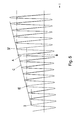
- FIG. 4 and 5 show a diagram of the simulated engine torque over time.
- Fig. 4 shows a complete transient from a first steady state (from point I to point II) to a second steady state (from point V to point VII).
- the first steady state ends approximately at point II, from where the torque steadily increases up to point V due to increased fuelling at constant engine speed. From point V the torque remains essentially constant at the second steady state.
- Fig. 4 and 5 represent the torque band of an engine comprising six cylinders. Therefore six consecutive peaks represent one full engine cycle.
- each first peak of an engine cycle (the peak corresponding to the master cylinder) are the peaks at points I, III, IV and VI.
- Curve A represented by a full line, represents the instantaneous effective torque for a simulation where the thermodynamic process in all cylinders is modeled. It can be seen that during load increase at constant speed of a 6 cylinder engine (from points II to V), the crank-angle resolved torque increases gradually over one engine cycle indicated by III to IV, where torque peaks due to firing of all 6 cylinders are observed.
- Curve B represented by a dashed line in Fig. 5 , represents the result for a simulation according to the invention, wherein only one master cylinder is simulated and the simulation parameters of five slave cylinders are determined by mapping without applying correction factors.
- a comparison between curve A and curve B shows that in steady state operation the results are nearly identical for both simulation approaches.
- point II and point V which is indicated by the sloped straight line C
- every first peak of a cycle (which represents the calculation of the master cylinder) is followed by five identical torque shapes of the slave cylinders (as is indicated by the cascading dotdashed lines).
- the inventive method according to the first aspect enables a significant reduction in computational times for the simulation of the models, however it also leads to lower fidelity of the results during transient engine operation.
- Reduction in the computational times is dependent on the number of cylinders, complexity of the gas path domain and applied integration time steps in the cylinder and gas path domain, however for 4 and 6 cylinder engines the application of the inventive approach results in approximately 50-65% reduction of the computational time of the complete engine model.
- the method uses a flux correction technique, which eliminates the cascading torque band while still benefiting from the master/slave- approach.
- the flux correction technique according to the invention relies on application of thermodynamical-ly derived correction factors to the values read out of the flux vector (eq. (1)) using a reformulated form of eq.
- X ⁇ C X ⁇ X ⁇ n + a - ⁇ X ⁇ n ⁇ n + a - ⁇ n , wherein C X represents the correction factor that is used to adapt a specific value ⁇ of a master cylinder in a way to more adequately reflect actual state of the slave cylinder at the latter time that corresponds to the shift of firing angles (The underscore denotes a corrected simulation output parameter.)
- C X is derived from a simulation or control input parameter, or calculated based on the changes of state variables, which have occurred in the time period that corresponds to the shift in firing angles between the master and slave cylinder, a high level of generality and high level of transferability of the flux correction approach can be ensured.
- This section comprises a non-limiting illustrative example of a flux correction technique applied to a simulation model.
- the outlined approach is applicable to four stroke engines.
- TDC firing top dead center
- TDC degree crank-angle
- BDC bottom dead center
- expansion stroke starts according to the piston kinematics at subsequent bottom dead center and thus at CD / 4, i.e. 180 degCA.
- Determination of correction factors for the flows through the intake ports can be based on the state variation in the intake manifold between the master and the slave cylinder which have occurred in the time period that corresponds to the shift in firing angles between the master and slave cylinder. It is assumed that the volumetric efficiency remains unchanged.
- the correction factors of the flows through the intake ports are calculated at intake valve opening (IVO), where IVO of the slave (S) and the master (M) cylinder refers to the intake valve opening of the corresponding cylinders and are thus shifted by a difference in the firing angles. During this time shift the state in the intake manifold generally changes leading to the necessity of applying the correction terms.
- the Flux correction approach of the flows through the intake ports thus yields:
- Correction factors for the heat flows to the combustion chamber walls can be determined according to the following scheme:
- Correction factors for the flows through the exhaust ports can be determined according to the following scheme:
- Fig. 6 represents a simulated torque during transient engine operation.
- Curve A represented by a full line, represents the instantaneous effective torque for a simulation where the thermodynamic process in all cylinders is modeled and curve D, represented by a dashed line, represents the result for a simulation according to the invention using the flux correction according to the Example described above. It can be seen that curve D closely follows curve A, which demonstrates that much more adequate transient results of the slave cylinders can be achieved by using the flux correction technique. It can be seen that the cascading steps of curve B in Fig. 5 can be avoided by applying the flux correction.
- FIG. 6 shows only results of the torque trace, whereas flux correction is applied also to all the flows through the mass and the heat transfer elements as outlined above. As flux correction is based on analytic formulas with very low CPU demand, there is no observable difference in the computational time of the model if flux correction is applied or not.
Landscapes
- Engineering & Computer Science (AREA)
- General Engineering & Computer Science (AREA)
- Combustion & Propulsion (AREA)
- Mechanical Engineering (AREA)
- Chemical & Material Sciences (AREA)
- Physics & Mathematics (AREA)
- Geometry (AREA)
- Computer Hardware Design (AREA)
- Theoretical Computer Science (AREA)
- General Physics & Mathematics (AREA)
- Microelectronics & Electronic Packaging (AREA)
- Evolutionary Computation (AREA)
- Computational Mathematics (AREA)
- Mathematical Analysis (AREA)
- Mathematical Optimization (AREA)
- Pure & Applied Mathematics (AREA)
- Combined Controls Of Internal Combustion Engines (AREA)
- Testing Of Engines (AREA)
Priority Applications (3)
| Application Number | Priority Date | Filing Date | Title |
|---|---|---|---|
| EP14170618.4A EP2949908B1 (fr) | 2014-05-30 | 2014-05-30 | Procédé de simulation d'un moteur à combustion interne |
| US14/725,388 US20150347648A1 (en) | 2014-05-30 | 2015-05-29 | Method for Simulation of an Internal Combustion Engine |
| JP2015109355A JP2015227662A (ja) | 2014-05-30 | 2015-05-29 | 内燃エンジンのシミュレーションの方法とその設備 |
Applications Claiming Priority (1)
| Application Number | Priority Date | Filing Date | Title |
|---|---|---|---|
| EP14170618.4A EP2949908B1 (fr) | 2014-05-30 | 2014-05-30 | Procédé de simulation d'un moteur à combustion interne |
Publications (2)
| Publication Number | Publication Date |
|---|---|
| EP2949908A1 true EP2949908A1 (fr) | 2015-12-02 |
| EP2949908B1 EP2949908B1 (fr) | 2016-07-06 |
Family
ID=50841647
Family Applications (1)
| Application Number | Title | Priority Date | Filing Date |
|---|---|---|---|
| EP14170618.4A Not-in-force EP2949908B1 (fr) | 2014-05-30 | 2014-05-30 | Procédé de simulation d'un moteur à combustion interne |
Country Status (3)
| Country | Link |
|---|---|
| US (1) | US20150347648A1 (fr) |
| EP (1) | EP2949908B1 (fr) |
| JP (1) | JP2015227662A (fr) |
Families Citing this family (4)
| Publication number | Priority date | Publication date | Assignee | Title |
|---|---|---|---|---|
| US20190243933A1 (en) * | 2018-02-07 | 2019-08-08 | Incucomm, Inc. | System and method that characterizes an object employing virtual representations thereof |
| CN110532716A (zh) * | 2019-09-04 | 2019-12-03 | 重庆大学 | 一种汽油机工作过程数值模拟系统 |
| CN112484075B (zh) * | 2020-12-01 | 2023-04-21 | 中国航发沈阳发动机研究所 | 一种燃烧室出口温度场修正方法 |
| CN115434802B (zh) * | 2022-09-15 | 2024-05-07 | 西安交通大学 | 氨-氢双燃料航空转子发动机多目标优化控制策略及系统 |
Citations (6)
| Publication number | Priority date | Publication date | Assignee | Title |
|---|---|---|---|---|
| US5771482A (en) * | 1995-12-15 | 1998-06-23 | The Ohio State University | Estimation of instantaneous indicated torque in multicylinder engines |
| US5806506A (en) * | 1996-08-01 | 1998-09-15 | Honda Giken Kogyo Kabushiki Kaisha | Cylinder-by-cylinder air-fuel ratio-estimating system for internal combustion engines |
| WO2008078097A1 (fr) | 2006-12-22 | 2008-07-03 | Ricardo Uk Limited | Procédé de simulation du fonctionnement d'un moteur |
| US20110083642A1 (en) * | 2009-09-09 | 2011-04-14 | Gm Global Technology Operations, Inc. | Method and device for closed-loop combustion control for an internal combustion engine |
| US20130090886A1 (en) | 2011-10-06 | 2013-04-11 | Dspace Digital Signal Processing And Control Engineering Gmbh | Method for real-time testing of a control unit for an internal combustion engine using a simulator |
| EP2579115B1 (fr) | 2011-10-06 | 2014-03-19 | dSPACE digital signal processing and control engineering GmbH | Procédé de tester un appareil de contrôle d'un moteur à combustion en temps réel moyennant un simulateur |
Family Cites Families (9)
| Publication number | Priority date | Publication date | Assignee | Title |
|---|---|---|---|---|
| US6708557B2 (en) * | 2002-02-13 | 2004-03-23 | Wisconsin Alumni Research Foundation | Internal combustion engine simulation and testing |
| US7848910B2 (en) * | 2004-07-22 | 2010-12-07 | Avl List Gmbh | Method for analyzing the behavior of complex systems, especially internal combustion engines |
| US7685871B2 (en) * | 2008-03-18 | 2010-03-30 | Delphi Technologies, Inc. | System and method for estimating engine internal residual fraction using single-cylinder simulation and measured cylinder pressure |
| US9037448B2 (en) * | 2009-08-07 | 2015-05-19 | Hitachi, Ltd. | Computer system, program, and method for assigning computational resource to be used in simulation |
| DE102010033433B4 (de) * | 2010-08-04 | 2021-11-25 | Dspace Digital Signal Processing And Control Engineering Gmbh | Schaltungsanordnung und Verfahren zur Simulation eines Sensors sowie entsprechende Simulatoreinrichtung |
| EP2661546B1 (fr) * | 2011-01-07 | 2017-06-21 | Delphi International Operations Luxembourg S.à r.l. | Moteur à combustion interne comprenant un post-traitement d'échappement et son procédé de fonctionnement |
| JP2012145059A (ja) * | 2011-01-13 | 2012-08-02 | Mitsubishi Heavy Ind Ltd | 内燃機関の燃焼制御方法および装置 |
| US10273886B2 (en) * | 2012-01-18 | 2019-04-30 | Toyota Motor Engineering & Manufacturing North America, Inc. | Process for reducing abnormal combustion within an internal combustion engine |
| JP5674903B1 (ja) * | 2013-11-15 | 2015-02-25 | 三菱電機株式会社 | 内燃機関の筒内圧推定装置 |
-
2014
- 2014-05-30 EP EP14170618.4A patent/EP2949908B1/fr not_active Not-in-force
-
2015
- 2015-05-29 JP JP2015109355A patent/JP2015227662A/ja active Pending
- 2015-05-29 US US14/725,388 patent/US20150347648A1/en not_active Abandoned
Patent Citations (6)
| Publication number | Priority date | Publication date | Assignee | Title |
|---|---|---|---|---|
| US5771482A (en) * | 1995-12-15 | 1998-06-23 | The Ohio State University | Estimation of instantaneous indicated torque in multicylinder engines |
| US5806506A (en) * | 1996-08-01 | 1998-09-15 | Honda Giken Kogyo Kabushiki Kaisha | Cylinder-by-cylinder air-fuel ratio-estimating system for internal combustion engines |
| WO2008078097A1 (fr) | 2006-12-22 | 2008-07-03 | Ricardo Uk Limited | Procédé de simulation du fonctionnement d'un moteur |
| US20110083642A1 (en) * | 2009-09-09 | 2011-04-14 | Gm Global Technology Operations, Inc. | Method and device for closed-loop combustion control for an internal combustion engine |
| US20130090886A1 (en) | 2011-10-06 | 2013-04-11 | Dspace Digital Signal Processing And Control Engineering Gmbh | Method for real-time testing of a control unit for an internal combustion engine using a simulator |
| EP2579115B1 (fr) | 2011-10-06 | 2014-03-19 | dSPACE digital signal processing and control engineering GmbH | Procédé de tester un appareil de contrôle d'un moteur à combustion en temps réel moyennant un simulateur |
Non-Patent Citations (2)
| Title |
|---|
| IFAC WORKSHOP ON ENGINE AND POWERTRAIN CONTROL, SIMULATION AND MODELING, vol. 3, no. 1, 2012, pages 162 - 169 |
| KATRASNIK, T. ET AL., TAILORED CYLINDER MODELS FOR SYSTEM LEVEL ENGINE MODELLING, 2012 |
Also Published As
| Publication number | Publication date |
|---|---|
| US20150347648A1 (en) | 2015-12-03 |
| EP2949908B1 (fr) | 2016-07-06 |
| JP2015227662A (ja) | 2015-12-17 |
Similar Documents
| Publication | Publication Date | Title |
|---|---|---|
| Rausen et al. | A mean-value model for control of homogeneous charge compression ignition (HCCI) engines | |
| Bondarenko et al. | Development of a diesel engine’s digital twin for predicting propulsion system dynamics | |
| EP2949908B1 (fr) | Procédé de simulation d'un moteur à combustion interne | |
| Grasreiner et al. | Model-based virtual engine calibration with the help of phenomenological methods for spark-ignited engines | |
| Sui et al. | Mean value modelling of diesel engine combustion based on parameterized finite stage cylinder process | |
| Casoli et al. | Development and validation of a “crank-angle” model of an automotive turbocharged Engine for HiL Applications | |
| Albrecht et al. | 1D simulation of turbocharged gasoline direct injection engine for transient strategy optimization | |
| Ashhab et al. | Control-oriented model for camless intake process—part I | |
| Martensson et al. | Modeling the effect of variable cam phasing on volumetric efficiency, scavenging and torque generation | |
| JP6752325B2 (ja) | 内燃機関の制御装置及び制御方法 | |
| Huang et al. | Development of a bond graph based model library for turbocharged diesel engines | |
| Lu et al. | Optimization method and simulation study of a diesel engine using full variable valve motions | |
| Benedetto et al. | Efficient combustion parameter prediction and performance optimization for a diesel engine with a low throughput combustion model | |
| Kakaee et al. | Simultaneous dynamic optimization of valves timing and waste gate to improve the load step transient response of a turbocharged spark ignition engine | |
| Larimore | Experimental analysis and control of recompression homogeneous charge compression ignition combustion at the high cyclic variability limit | |
| Gambarotta | Control-Oriented “Crank-Angle” Based Modeling of Automotive Engines | |
| JP7308480B2 (ja) | 燃焼機関の実時間性能予測方法及び実時間性能予測プログラム | |
| Katrašnik et al. | On the Convergence, Stability, and Computational Speed of Numerical Schemes for 0-D IC Engine Cylinder Modelling | |
| Albrecht et al. | Observer design for downsized gasoline engine control using 1D engine simulation | |
| Bohbot et al. | A new coupling approach using a 1D system simulation software and a 3D combustion code applied to transient engine operation | |
| Singh et al. | Automated engine calibration optimization using online extremum seeking | |
| Katrašnik et al. | Tailored cylinder models for system level engine modelling | |
| Edelberg et al. | A high level approach to mean value modeling of an automotive engine during cold-start | |
| JP2008008236A (ja) | 4サイクル多気筒ガスエンジンのシミュレーション方法と装置 | |
| Jianan et al. | Online automatic adaptation for model-based control of diesel engine |
Legal Events
| Date | Code | Title | Description |
|---|---|---|---|
| 17P | Request for examination filed |
Effective date: 20150320 |
|
| AK | Designated contracting states |
Kind code of ref document: A1 Designated state(s): AL AT BE BG CH CY CZ DE DK EE ES FI FR GB GR HR HU IE IS IT LI LT LU LV MC MK MT NL NO PL PT RO RS SE SI SK SM TR |
|
| AX | Request for extension of the european patent |
Extension state: BA ME |
|
| PUAI | Public reference made under article 153(3) epc to a published international application that has entered the european phase |
Free format text: ORIGINAL CODE: 0009012 |
|
| RIC1 | Information provided on ipc code assigned before grant |
Ipc: F02D 41/24 20060101AFI20160204BHEP Ipc: F02D 41/26 20060101ALI20160204BHEP Ipc: F02D 35/02 20060101ALN20160204BHEP Ipc: F02D 41/00 20060101ALI20160204BHEP |
|
| GRAP | Despatch of communication of intention to grant a patent |
Free format text: ORIGINAL CODE: EPIDOSNIGR1 |
|
| INTG | Intention to grant announced |
Effective date: 20160315 |
|
| GRAS | Grant fee paid |
Free format text: ORIGINAL CODE: EPIDOSNIGR3 |
|
| GRAA | (expected) grant |
Free format text: ORIGINAL CODE: 0009210 |
|
| AK | Designated contracting states |
Kind code of ref document: B1 Designated state(s): AL AT BE BG CH CY CZ DE DK EE ES FI FR GB GR HR HU IE IS IT LI LT LU LV MC MK MT NL NO PL PT RO RS SE SI SK SM TR |
|
| REG | Reference to a national code |
Ref country code: GB Ref legal event code: FG4D |
|
| REG | Reference to a national code |
Ref country code: AT Ref legal event code: REF Ref document number: 810909 Country of ref document: AT Kind code of ref document: T Effective date: 20160715 Ref country code: CH Ref legal event code: EP |
|
| REG | Reference to a national code |
Ref country code: IE Ref legal event code: FG4D |
|
| REG | Reference to a national code |
Ref country code: DE Ref legal event code: R096 Ref document number: 602014002556 Country of ref document: DE |
|
| REG | Reference to a national code |
Ref country code: NL Ref legal event code: MP Effective date: 20160706 |
|
| REG | Reference to a national code |
Ref country code: LT Ref legal event code: MG4D |
|
| REG | Reference to a national code |
Ref country code: AT Ref legal event code: MK05 Ref document number: 810909 Country of ref document: AT Kind code of ref document: T Effective date: 20160706 |
|
| PG25 | Lapsed in a contracting state [announced via postgrant information from national office to epo] |
Ref country code: NO Free format text: LAPSE BECAUSE OF FAILURE TO SUBMIT A TRANSLATION OF THE DESCRIPTION OR TO PAY THE FEE WITHIN THE PRESCRIBED TIME-LIMIT Effective date: 20161006 Ref country code: HR Free format text: LAPSE BECAUSE OF FAILURE TO SUBMIT A TRANSLATION OF THE DESCRIPTION OR TO PAY THE FEE WITHIN THE PRESCRIBED TIME-LIMIT Effective date: 20160706 Ref country code: IS Free format text: LAPSE BECAUSE OF FAILURE TO SUBMIT A TRANSLATION OF THE DESCRIPTION OR TO PAY THE FEE WITHIN THE PRESCRIBED TIME-LIMIT Effective date: 20161106 Ref country code: LT Free format text: LAPSE BECAUSE OF FAILURE TO SUBMIT A TRANSLATION OF THE DESCRIPTION OR TO PAY THE FEE WITHIN THE PRESCRIBED TIME-LIMIT Effective date: 20160706 Ref country code: NL Free format text: LAPSE BECAUSE OF FAILURE TO SUBMIT A TRANSLATION OF THE DESCRIPTION OR TO PAY THE FEE WITHIN THE PRESCRIBED TIME-LIMIT Effective date: 20160706 Ref country code: FI Free format text: LAPSE BECAUSE OF FAILURE TO SUBMIT A TRANSLATION OF THE DESCRIPTION OR TO PAY THE FEE WITHIN THE PRESCRIBED TIME-LIMIT Effective date: 20160706 Ref country code: RS Free format text: LAPSE BECAUSE OF FAILURE TO SUBMIT A TRANSLATION OF THE DESCRIPTION OR TO PAY THE FEE WITHIN THE PRESCRIBED TIME-LIMIT Effective date: 20160706 |
|
| PG25 | Lapsed in a contracting state [announced via postgrant information from national office to epo] |
Ref country code: BE Free format text: LAPSE BECAUSE OF FAILURE TO SUBMIT A TRANSLATION OF THE DESCRIPTION OR TO PAY THE FEE WITHIN THE PRESCRIBED TIME-LIMIT Effective date: 20160706 Ref country code: AT Free format text: LAPSE BECAUSE OF FAILURE TO SUBMIT A TRANSLATION OF THE DESCRIPTION OR TO PAY THE FEE WITHIN THE PRESCRIBED TIME-LIMIT Effective date: 20160706 Ref country code: ES Free format text: LAPSE BECAUSE OF FAILURE TO SUBMIT A TRANSLATION OF THE DESCRIPTION OR TO PAY THE FEE WITHIN THE PRESCRIBED TIME-LIMIT Effective date: 20160706 Ref country code: LV Free format text: LAPSE BECAUSE OF FAILURE TO SUBMIT A TRANSLATION OF THE DESCRIPTION OR TO PAY THE FEE WITHIN THE PRESCRIBED TIME-LIMIT Effective date: 20160706 Ref country code: PL Free format text: LAPSE BECAUSE OF FAILURE TO SUBMIT A TRANSLATION OF THE DESCRIPTION OR TO PAY THE FEE WITHIN THE PRESCRIBED TIME-LIMIT Effective date: 20160706 Ref country code: PT Free format text: LAPSE BECAUSE OF FAILURE TO SUBMIT A TRANSLATION OF THE DESCRIPTION OR TO PAY THE FEE WITHIN THE PRESCRIBED TIME-LIMIT Effective date: 20161107 Ref country code: SE Free format text: LAPSE BECAUSE OF FAILURE TO SUBMIT A TRANSLATION OF THE DESCRIPTION OR TO PAY THE FEE WITHIN THE PRESCRIBED TIME-LIMIT Effective date: 20160706 Ref country code: GR Free format text: LAPSE BECAUSE OF FAILURE TO SUBMIT A TRANSLATION OF THE DESCRIPTION OR TO PAY THE FEE WITHIN THE PRESCRIBED TIME-LIMIT Effective date: 20161007 |
|
| REG | Reference to a national code |
Ref country code: DE Ref legal event code: R097 Ref document number: 602014002556 Country of ref document: DE |
|
| PG25 | Lapsed in a contracting state [announced via postgrant information from national office to epo] |
Ref country code: RO Free format text: LAPSE BECAUSE OF FAILURE TO SUBMIT A TRANSLATION OF THE DESCRIPTION OR TO PAY THE FEE WITHIN THE PRESCRIBED TIME-LIMIT Effective date: 20160706 Ref country code: EE Free format text: LAPSE BECAUSE OF FAILURE TO SUBMIT A TRANSLATION OF THE DESCRIPTION OR TO PAY THE FEE WITHIN THE PRESCRIBED TIME-LIMIT Effective date: 20160706 |
|
| PLBE | No opposition filed within time limit |
Free format text: ORIGINAL CODE: 0009261 |
|
| STAA | Information on the status of an ep patent application or granted ep patent |
Free format text: STATUS: NO OPPOSITION FILED WITHIN TIME LIMIT |
|
| REG | Reference to a national code |
Ref country code: FR Ref legal event code: PLFP Year of fee payment: 4 |
|
| PG25 | Lapsed in a contracting state [announced via postgrant information from national office to epo] |
Ref country code: SM Free format text: LAPSE BECAUSE OF FAILURE TO SUBMIT A TRANSLATION OF THE DESCRIPTION OR TO PAY THE FEE WITHIN THE PRESCRIBED TIME-LIMIT Effective date: 20160706 Ref country code: DK Free format text: LAPSE BECAUSE OF FAILURE TO SUBMIT A TRANSLATION OF THE DESCRIPTION OR TO PAY THE FEE WITHIN THE PRESCRIBED TIME-LIMIT Effective date: 20160706 Ref country code: SK Free format text: LAPSE BECAUSE OF FAILURE TO SUBMIT A TRANSLATION OF THE DESCRIPTION OR TO PAY THE FEE WITHIN THE PRESCRIBED TIME-LIMIT Effective date: 20160706 Ref country code: CZ Free format text: LAPSE BECAUSE OF FAILURE TO SUBMIT A TRANSLATION OF THE DESCRIPTION OR TO PAY THE FEE WITHIN THE PRESCRIBED TIME-LIMIT Effective date: 20160706 Ref country code: BG Free format text: LAPSE BECAUSE OF FAILURE TO SUBMIT A TRANSLATION OF THE DESCRIPTION OR TO PAY THE FEE WITHIN THE PRESCRIBED TIME-LIMIT Effective date: 20161006 |
|
| 26N | No opposition filed |
Effective date: 20170407 |
|
| PG25 | Lapsed in a contracting state [announced via postgrant information from national office to epo] |
Ref country code: LU Free format text: LAPSE BECAUSE OF NON-PAYMENT OF DUE FEES Effective date: 20170531 Ref country code: SI Free format text: LAPSE BECAUSE OF FAILURE TO SUBMIT A TRANSLATION OF THE DESCRIPTION OR TO PAY THE FEE WITHIN THE PRESCRIBED TIME-LIMIT Effective date: 20160706 |
|
| REG | Reference to a national code |
Ref country code: CH Ref legal event code: PL |
|
| PG25 | Lapsed in a contracting state [announced via postgrant information from national office to epo] |
Ref country code: MC Free format text: LAPSE BECAUSE OF FAILURE TO SUBMIT A TRANSLATION OF THE DESCRIPTION OR TO PAY THE FEE WITHIN THE PRESCRIBED TIME-LIMIT Effective date: 20160706 |
|
| REG | Reference to a national code |
Ref country code: IE Ref legal event code: MM4A |
|
| PG25 | Lapsed in a contracting state [announced via postgrant information from national office to epo] |
Ref country code: LI Free format text: LAPSE BECAUSE OF NON-PAYMENT OF DUE FEES Effective date: 20170531 Ref country code: CH Free format text: LAPSE BECAUSE OF NON-PAYMENT OF DUE FEES Effective date: 20170531 |
|
| PG25 | Lapsed in a contracting state [announced via postgrant information from national office to epo] |
Ref country code: LU Free format text: LAPSE BECAUSE OF NON-PAYMENT OF DUE FEES Effective date: 20170530 |
|
| PG25 | Lapsed in a contracting state [announced via postgrant information from national office to epo] |
Ref country code: IE Free format text: LAPSE BECAUSE OF NON-PAYMENT OF DUE FEES Effective date: 20170530 |
|
| REG | Reference to a national code |
Ref country code: FR Ref legal event code: PLFP Year of fee payment: 5 |
|
| PG25 | Lapsed in a contracting state [announced via postgrant information from national office to epo] |
Ref country code: MT Free format text: LAPSE BECAUSE OF NON-PAYMENT OF DUE FEES Effective date: 20170530 |
|
| PG25 | Lapsed in a contracting state [announced via postgrant information from national office to epo] |
Ref country code: AL Free format text: LAPSE BECAUSE OF FAILURE TO SUBMIT A TRANSLATION OF THE DESCRIPTION OR TO PAY THE FEE WITHIN THE PRESCRIBED TIME-LIMIT Effective date: 20160706 |
|
| PG25 | Lapsed in a contracting state [announced via postgrant information from national office to epo] |
Ref country code: HU Free format text: LAPSE BECAUSE OF FAILURE TO SUBMIT A TRANSLATION OF THE DESCRIPTION OR TO PAY THE FEE WITHIN THE PRESCRIBED TIME-LIMIT; INVALID AB INITIO Effective date: 20140530 |
|
| PG25 | Lapsed in a contracting state [announced via postgrant information from national office to epo] |
Ref country code: CY Free format text: LAPSE BECAUSE OF FAILURE TO SUBMIT A TRANSLATION OF THE DESCRIPTION OR TO PAY THE FEE WITHIN THE PRESCRIBED TIME-LIMIT Effective date: 20160706 |
|
| PG25 | Lapsed in a contracting state [announced via postgrant information from national office to epo] |
Ref country code: MK Free format text: LAPSE BECAUSE OF FAILURE TO SUBMIT A TRANSLATION OF THE DESCRIPTION OR TO PAY THE FEE WITHIN THE PRESCRIBED TIME-LIMIT Effective date: 20160706 |
|
| PG25 | Lapsed in a contracting state [announced via postgrant information from national office to epo] |
Ref country code: TR Free format text: LAPSE BECAUSE OF FAILURE TO SUBMIT A TRANSLATION OF THE DESCRIPTION OR TO PAY THE FEE WITHIN THE PRESCRIBED TIME-LIMIT Effective date: 20160706 |
|
| PGFP | Annual fee paid to national office [announced via postgrant information from national office to epo] |
Ref country code: FR Payment date: 20210511 Year of fee payment: 8 Ref country code: DE Payment date: 20210519 Year of fee payment: 8 Ref country code: IT Payment date: 20210518 Year of fee payment: 8 |
|
| PGFP | Annual fee paid to national office [announced via postgrant information from national office to epo] |
Ref country code: GB Payment date: 20210511 Year of fee payment: 8 |
|
| REG | Reference to a national code |
Ref country code: DE Ref legal event code: R119 Ref document number: 602014002556 Country of ref document: DE |
|
| GBPC | Gb: european patent ceased through non-payment of renewal fee |
Effective date: 20220530 |
|
| PG25 | Lapsed in a contracting state [announced via postgrant information from national office to epo] |
Ref country code: FR Free format text: LAPSE BECAUSE OF NON-PAYMENT OF DUE FEES Effective date: 20220531 |
|
| PG25 | Lapsed in a contracting state [announced via postgrant information from national office to epo] |
Ref country code: GB Free format text: LAPSE BECAUSE OF NON-PAYMENT OF DUE FEES Effective date: 20220530 Ref country code: DE Free format text: LAPSE BECAUSE OF NON-PAYMENT OF DUE FEES Effective date: 20221201 |
|
| PG25 | Lapsed in a contracting state [announced via postgrant information from national office to epo] |
Ref country code: IT Free format text: LAPSE BECAUSE OF NON-PAYMENT OF DUE FEES Effective date: 20220530 |