EP2947062B1 - Method for joining ceramic to metal - Google Patents
Method for joining ceramic to metal Download PDFInfo
- Publication number
- EP2947062B1 EP2947062B1 EP15168809.0A EP15168809A EP2947062B1 EP 2947062 B1 EP2947062 B1 EP 2947062B1 EP 15168809 A EP15168809 A EP 15168809A EP 2947062 B1 EP2947062 B1 EP 2947062B1
- Authority
- EP
- European Patent Office
- Prior art keywords
- layer
- barrier layer
- metal
- ceramic
- metallic
- Prior art date
- Legal status (The legal status is an assumption and is not a legal conclusion. Google has not performed a legal analysis and makes no representation as to the accuracy of the status listed.)
- Active
Links
Images




Classifications
-
- H—ELECTRICITY
- H01—ELECTRIC ELEMENTS
- H01M—PROCESSES OR MEANS, e.g. BATTERIES, FOR THE DIRECT CONVERSION OF CHEMICAL ENERGY INTO ELECTRICAL ENERGY
- H01M10/00—Secondary cells; Manufacture thereof
- H01M10/36—Accumulators not provided for in groups H01M10/05-H01M10/34
- H01M10/39—Accumulators not provided for in groups H01M10/05-H01M10/34 working at high temperature
- H01M10/3909—Sodium-sulfur cells
- H01M10/3963—Sealing means between the solid electrolyte and holders
-
- B—PERFORMING OPERATIONS; TRANSPORTING
- B23—MACHINE TOOLS; METAL-WORKING NOT OTHERWISE PROVIDED FOR
- B23K—SOLDERING OR UNSOLDERING; WELDING; CLADDING OR PLATING BY SOLDERING OR WELDING; CUTTING BY APPLYING HEAT LOCALLY, e.g. FLAME CUTTING; WORKING BY LASER BEAM
- B23K35/00—Rods, electrodes, materials, or media, for use in soldering, welding, or cutting
- B23K35/22—Rods, electrodes, materials, or media, for use in soldering, welding, or cutting characterised by the composition or nature of the material
- B23K35/24—Selection of soldering or welding materials proper
- B23K35/30—Selection of soldering or welding materials proper with the principal constituent melting at less than 1550°C
- B23K35/3033—Ni as the principal constituent
-
- B—PERFORMING OPERATIONS; TRANSPORTING
- B23—MACHINE TOOLS; METAL-WORKING NOT OTHERWISE PROVIDED FOR
- B23K—SOLDERING OR UNSOLDERING; WELDING; CLADDING OR PLATING BY SOLDERING OR WELDING; CUTTING BY APPLYING HEAT LOCALLY, e.g. FLAME CUTTING; WORKING BY LASER BEAM
- B23K35/00—Rods, electrodes, materials, or media, for use in soldering, welding, or cutting
- B23K35/22—Rods, electrodes, materials, or media, for use in soldering, welding, or cutting characterised by the composition or nature of the material
- B23K35/24—Selection of soldering or welding materials proper
- B23K35/30—Selection of soldering or welding materials proper with the principal constituent melting at less than 1550°C
- B23K35/3046—Co as the principal constituent
-
- C—CHEMISTRY; METALLURGY
- C04—CEMENTS; CONCRETE; ARTIFICIAL STONE; CERAMICS; REFRACTORIES
- C04B—LIME, MAGNESIA; SLAG; CEMENTS; COMPOSITIONS THEREOF, e.g. MORTARS, CONCRETE OR LIKE BUILDING MATERIALS; ARTIFICIAL STONE; CERAMICS; REFRACTORIES; TREATMENT OF NATURAL STONE
- C04B37/00—Joining burned ceramic articles with other burned ceramic articles or other articles by heating
- C04B37/02—Joining burned ceramic articles with other burned ceramic articles or other articles by heating with metallic articles
- C04B37/023—Joining burned ceramic articles with other burned ceramic articles or other articles by heating with metallic articles characterised by the interlayer used
- C04B37/026—Joining burned ceramic articles with other burned ceramic articles or other articles by heating with metallic articles characterised by the interlayer used consisting of metals or metal salts
-
- H—ELECTRICITY
- H01—ELECTRIC ELEMENTS
- H01M—PROCESSES OR MEANS, e.g. BATTERIES, FOR THE DIRECT CONVERSION OF CHEMICAL ENERGY INTO ELECTRICAL ENERGY
- H01M50/00—Constructional details or processes of manufacture of the non-active parts of electrochemical cells other than fuel cells, e.g. hybrid cells
- H01M50/10—Primary casings; Jackets or wrappings
- H01M50/183—Sealing members
- H01M50/184—Sealing members characterised by their shape or structure
-
- H—ELECTRICITY
- H01—ELECTRIC ELEMENTS
- H01M—PROCESSES OR MEANS, e.g. BATTERIES, FOR THE DIRECT CONVERSION OF CHEMICAL ENERGY INTO ELECTRICAL ENERGY
- H01M50/00—Constructional details or processes of manufacture of the non-active parts of electrochemical cells other than fuel cells, e.g. hybrid cells
- H01M50/10—Primary casings; Jackets or wrappings
- H01M50/183—Sealing members
- H01M50/186—Sealing members characterised by the disposition of the sealing members
-
- H—ELECTRICITY
- H01—ELECTRIC ELEMENTS
- H01M—PROCESSES OR MEANS, e.g. BATTERIES, FOR THE DIRECT CONVERSION OF CHEMICAL ENERGY INTO ELECTRICAL ENERGY
- H01M50/00—Constructional details or processes of manufacture of the non-active parts of electrochemical cells other than fuel cells, e.g. hybrid cells
- H01M50/10—Primary casings; Jackets or wrappings
- H01M50/183—Sealing members
- H01M50/19—Sealing members characterised by the material
- H01M50/191—Inorganic material
-
- H—ELECTRICITY
- H01—ELECTRIC ELEMENTS
- H01M—PROCESSES OR MEANS, e.g. BATTERIES, FOR THE DIRECT CONVERSION OF CHEMICAL ENERGY INTO ELECTRICAL ENERGY
- H01M50/00—Constructional details or processes of manufacture of the non-active parts of electrochemical cells other than fuel cells, e.g. hybrid cells
- H01M50/10—Primary casings; Jackets or wrappings
- H01M50/183—Sealing members
- H01M50/19—Sealing members characterised by the material
- H01M50/197—Sealing members characterised by the material having a layered structure
-
- C—CHEMISTRY; METALLURGY
- C04—CEMENTS; CONCRETE; ARTIFICIAL STONE; CERAMICS; REFRACTORIES
- C04B—LIME, MAGNESIA; SLAG; CEMENTS; COMPOSITIONS THEREOF, e.g. MORTARS, CONCRETE OR LIKE BUILDING MATERIALS; ARTIFICIAL STONE; CERAMICS; REFRACTORIES; TREATMENT OF NATURAL STONE
- C04B2235/00—Aspects relating to ceramic starting mixtures or sintered ceramic products
- C04B2235/65—Aspects relating to heat treatments of ceramic bodies such as green ceramics or pre-sintered ceramics, e.g. burning, sintering or melting processes
- C04B2235/656—Aspects relating to heat treatments of ceramic bodies such as green ceramics or pre-sintered ceramics, e.g. burning, sintering or melting processes characterised by specific heating conditions during heat treatment
-
- C—CHEMISTRY; METALLURGY
- C04—CEMENTS; CONCRETE; ARTIFICIAL STONE; CERAMICS; REFRACTORIES
- C04B—LIME, MAGNESIA; SLAG; CEMENTS; COMPOSITIONS THEREOF, e.g. MORTARS, CONCRETE OR LIKE BUILDING MATERIALS; ARTIFICIAL STONE; CERAMICS; REFRACTORIES; TREATMENT OF NATURAL STONE
- C04B2235/00—Aspects relating to ceramic starting mixtures or sintered ceramic products
- C04B2235/65—Aspects relating to heat treatments of ceramic bodies such as green ceramics or pre-sintered ceramics, e.g. burning, sintering or melting processes
- C04B2235/656—Aspects relating to heat treatments of ceramic bodies such as green ceramics or pre-sintered ceramics, e.g. burning, sintering or melting processes characterised by specific heating conditions during heat treatment
- C04B2235/6567—Treatment time
-
- C—CHEMISTRY; METALLURGY
- C04—CEMENTS; CONCRETE; ARTIFICIAL STONE; CERAMICS; REFRACTORIES
- C04B—LIME, MAGNESIA; SLAG; CEMENTS; COMPOSITIONS THEREOF, e.g. MORTARS, CONCRETE OR LIKE BUILDING MATERIALS; ARTIFICIAL STONE; CERAMICS; REFRACTORIES; TREATMENT OF NATURAL STONE
- C04B2235/00—Aspects relating to ceramic starting mixtures or sintered ceramic products
- C04B2235/65—Aspects relating to heat treatments of ceramic bodies such as green ceramics or pre-sintered ceramics, e.g. burning, sintering or melting processes
- C04B2235/658—Atmosphere during thermal treatment
- C04B2235/6582—Hydrogen containing atmosphere
-
- C—CHEMISTRY; METALLURGY
- C04—CEMENTS; CONCRETE; ARTIFICIAL STONE; CERAMICS; REFRACTORIES
- C04B—LIME, MAGNESIA; SLAG; CEMENTS; COMPOSITIONS THEREOF, e.g. MORTARS, CONCRETE OR LIKE BUILDING MATERIALS; ARTIFICIAL STONE; CERAMICS; REFRACTORIES; TREATMENT OF NATURAL STONE
- C04B2237/00—Aspects relating to ceramic laminates or to joining of ceramic articles with other articles by heating
- C04B2237/02—Aspects relating to interlayers, e.g. used to join ceramic articles with other articles by heating
- C04B2237/12—Metallic interlayers
- C04B2237/122—Metallic interlayers based on refractory metals
-
- C—CHEMISTRY; METALLURGY
- C04—CEMENTS; CONCRETE; ARTIFICIAL STONE; CERAMICS; REFRACTORIES
- C04B—LIME, MAGNESIA; SLAG; CEMENTS; COMPOSITIONS THEREOF, e.g. MORTARS, CONCRETE OR LIKE BUILDING MATERIALS; ARTIFICIAL STONE; CERAMICS; REFRACTORIES; TREATMENT OF NATURAL STONE
- C04B2237/00—Aspects relating to ceramic laminates or to joining of ceramic articles with other articles by heating
- C04B2237/02—Aspects relating to interlayers, e.g. used to join ceramic articles with other articles by heating
- C04B2237/12—Metallic interlayers
- C04B2237/123—Metallic interlayers based on iron group metals, e.g. steel
-
- C—CHEMISTRY; METALLURGY
- C04—CEMENTS; CONCRETE; ARTIFICIAL STONE; CERAMICS; REFRACTORIES
- C04B—LIME, MAGNESIA; SLAG; CEMENTS; COMPOSITIONS THEREOF, e.g. MORTARS, CONCRETE OR LIKE BUILDING MATERIALS; ARTIFICIAL STONE; CERAMICS; REFRACTORIES; TREATMENT OF NATURAL STONE
- C04B2237/00—Aspects relating to ceramic laminates or to joining of ceramic articles with other articles by heating
- C04B2237/02—Aspects relating to interlayers, e.g. used to join ceramic articles with other articles by heating
- C04B2237/12—Metallic interlayers
- C04B2237/126—Metallic interlayers wherein the active component for bonding is not the largest fraction of the interlayer
-
- C—CHEMISTRY; METALLURGY
- C04—CEMENTS; CONCRETE; ARTIFICIAL STONE; CERAMICS; REFRACTORIES
- C04B—LIME, MAGNESIA; SLAG; CEMENTS; COMPOSITIONS THEREOF, e.g. MORTARS, CONCRETE OR LIKE BUILDING MATERIALS; ARTIFICIAL STONE; CERAMICS; REFRACTORIES; TREATMENT OF NATURAL STONE
- C04B2237/00—Aspects relating to ceramic laminates or to joining of ceramic articles with other articles by heating
- C04B2237/02—Aspects relating to interlayers, e.g. used to join ceramic articles with other articles by heating
- C04B2237/12—Metallic interlayers
- C04B2237/126—Metallic interlayers wherein the active component for bonding is not the largest fraction of the interlayer
- C04B2237/127—The active component for bonding being a refractory metal
-
- C—CHEMISTRY; METALLURGY
- C04—CEMENTS; CONCRETE; ARTIFICIAL STONE; CERAMICS; REFRACTORIES
- C04B—LIME, MAGNESIA; SLAG; CEMENTS; COMPOSITIONS THEREOF, e.g. MORTARS, CONCRETE OR LIKE BUILDING MATERIALS; ARTIFICIAL STONE; CERAMICS; REFRACTORIES; TREATMENT OF NATURAL STONE
- C04B2237/00—Aspects relating to ceramic laminates or to joining of ceramic articles with other articles by heating
- C04B2237/02—Aspects relating to interlayers, e.g. used to join ceramic articles with other articles by heating
- C04B2237/12—Metallic interlayers
- C04B2237/126—Metallic interlayers wherein the active component for bonding is not the largest fraction of the interlayer
- C04B2237/128—The active component for bonding being silicon
-
- C—CHEMISTRY; METALLURGY
- C04—CEMENTS; CONCRETE; ARTIFICIAL STONE; CERAMICS; REFRACTORIES
- C04B—LIME, MAGNESIA; SLAG; CEMENTS; COMPOSITIONS THEREOF, e.g. MORTARS, CONCRETE OR LIKE BUILDING MATERIALS; ARTIFICIAL STONE; CERAMICS; REFRACTORIES; TREATMENT OF NATURAL STONE
- C04B2237/00—Aspects relating to ceramic laminates or to joining of ceramic articles with other articles by heating
- C04B2237/30—Composition of layers of ceramic laminates or of ceramic or metallic articles to be joined by heating, e.g. Si substrates
- C04B2237/32—Ceramic
- C04B2237/34—Oxidic
- C04B2237/343—Alumina or aluminates
-
- C—CHEMISTRY; METALLURGY
- C04—CEMENTS; CONCRETE; ARTIFICIAL STONE; CERAMICS; REFRACTORIES
- C04B—LIME, MAGNESIA; SLAG; CEMENTS; COMPOSITIONS THEREOF, e.g. MORTARS, CONCRETE OR LIKE BUILDING MATERIALS; ARTIFICIAL STONE; CERAMICS; REFRACTORIES; TREATMENT OF NATURAL STONE
- C04B2237/00—Aspects relating to ceramic laminates or to joining of ceramic articles with other articles by heating
- C04B2237/30—Composition of layers of ceramic laminates or of ceramic or metallic articles to be joined by heating, e.g. Si substrates
- C04B2237/40—Metallic
- C04B2237/405—Iron metal group, e.g. Co or Ni
-
- C—CHEMISTRY; METALLURGY
- C04—CEMENTS; CONCRETE; ARTIFICIAL STONE; CERAMICS; REFRACTORIES
- C04B—LIME, MAGNESIA; SLAG; CEMENTS; COMPOSITIONS THEREOF, e.g. MORTARS, CONCRETE OR LIKE BUILDING MATERIALS; ARTIFICIAL STONE; CERAMICS; REFRACTORIES; TREATMENT OF NATURAL STONE
- C04B2237/00—Aspects relating to ceramic laminates or to joining of ceramic articles with other articles by heating
- C04B2237/50—Processing aspects relating to ceramic laminates or to the joining of ceramic articles with other articles by heating
- C04B2237/55—Pre-treatments of a coated or not coated substrate other than oxidation treatment in order to form an active joining layer
-
- C—CHEMISTRY; METALLURGY
- C04—CEMENTS; CONCRETE; ARTIFICIAL STONE; CERAMICS; REFRACTORIES
- C04B—LIME, MAGNESIA; SLAG; CEMENTS; COMPOSITIONS THEREOF, e.g. MORTARS, CONCRETE OR LIKE BUILDING MATERIALS; ARTIFICIAL STONE; CERAMICS; REFRACTORIES; TREATMENT OF NATURAL STONE
- C04B2237/00—Aspects relating to ceramic laminates or to joining of ceramic articles with other articles by heating
- C04B2237/50—Processing aspects relating to ceramic laminates or to the joining of ceramic articles with other articles by heating
- C04B2237/59—Aspects relating to the structure of the interlayer
- C04B2237/597—Aspects relating to the structure of the interlayer whereby the interlayer is continuous but porous, e.g. containing hollow or porous particles, macro- or micropores or cracks
-
- C—CHEMISTRY; METALLURGY
- C04—CEMENTS; CONCRETE; ARTIFICIAL STONE; CERAMICS; REFRACTORIES
- C04B—LIME, MAGNESIA; SLAG; CEMENTS; COMPOSITIONS THEREOF, e.g. MORTARS, CONCRETE OR LIKE BUILDING MATERIALS; ARTIFICIAL STONE; CERAMICS; REFRACTORIES; TREATMENT OF NATURAL STONE
- C04B2237/00—Aspects relating to ceramic laminates or to joining of ceramic articles with other articles by heating
- C04B2237/50—Processing aspects relating to ceramic laminates or to the joining of ceramic articles with other articles by heating
- C04B2237/70—Forming laminates or joined articles comprising layers of a specific, unusual thickness
- C04B2237/708—Forming laminates or joined articles comprising layers of a specific, unusual thickness of one or more of the interlayers
-
- C—CHEMISTRY; METALLURGY
- C04—CEMENTS; CONCRETE; ARTIFICIAL STONE; CERAMICS; REFRACTORIES
- C04B—LIME, MAGNESIA; SLAG; CEMENTS; COMPOSITIONS THEREOF, e.g. MORTARS, CONCRETE OR LIKE BUILDING MATERIALS; ARTIFICIAL STONE; CERAMICS; REFRACTORIES; TREATMENT OF NATURAL STONE
- C04B2237/00—Aspects relating to ceramic laminates or to joining of ceramic articles with other articles by heating
- C04B2237/50—Processing aspects relating to ceramic laminates or to the joining of ceramic articles with other articles by heating
- C04B2237/72—Forming laminates or joined articles comprising at least two interlayers directly next to each other
-
- C—CHEMISTRY; METALLURGY
- C04—CEMENTS; CONCRETE; ARTIFICIAL STONE; CERAMICS; REFRACTORIES
- C04B—LIME, MAGNESIA; SLAG; CEMENTS; COMPOSITIONS THEREOF, e.g. MORTARS, CONCRETE OR LIKE BUILDING MATERIALS; ARTIFICIAL STONE; CERAMICS; REFRACTORIES; TREATMENT OF NATURAL STONE
- C04B2237/00—Aspects relating to ceramic laminates or to joining of ceramic articles with other articles by heating
- C04B2237/50—Processing aspects relating to ceramic laminates or to the joining of ceramic articles with other articles by heating
- C04B2237/76—Forming laminates or joined articles comprising at least one member in the form other than a sheet or disc, e.g. two tubes or a tube and a sheet or disc
- C04B2237/765—Forming laminates or joined articles comprising at least one member in the form other than a sheet or disc, e.g. two tubes or a tube and a sheet or disc at least one member being a tube
-
- C—CHEMISTRY; METALLURGY
- C04—CEMENTS; CONCRETE; ARTIFICIAL STONE; CERAMICS; REFRACTORIES
- C04B—LIME, MAGNESIA; SLAG; CEMENTS; COMPOSITIONS THEREOF, e.g. MORTARS, CONCRETE OR LIKE BUILDING MATERIALS; ARTIFICIAL STONE; CERAMICS; REFRACTORIES; TREATMENT OF NATURAL STONE
- C04B2237/00—Aspects relating to ceramic laminates or to joining of ceramic articles with other articles by heating
- C04B2237/50—Processing aspects relating to ceramic laminates or to the joining of ceramic articles with other articles by heating
- C04B2237/80—Joining the largest surface of one substrate with a smaller surface of the other substrate, e.g. butt joining or forming a T-joint
-
- Y—GENERAL TAGGING OF NEW TECHNOLOGICAL DEVELOPMENTS; GENERAL TAGGING OF CROSS-SECTIONAL TECHNOLOGIES SPANNING OVER SEVERAL SECTIONS OF THE IPC; TECHNICAL SUBJECTS COVERED BY FORMER USPC CROSS-REFERENCE ART COLLECTIONS [XRACs] AND DIGESTS
- Y02—TECHNOLOGIES OR APPLICATIONS FOR MITIGATION OR ADAPTATION AGAINST CLIMATE CHANGE
- Y02E—REDUCTION OF GREENHOUSE GAS [GHG] EMISSIONS, RELATED TO ENERGY GENERATION, TRANSMISSION OR DISTRIBUTION
- Y02E60/00—Enabling technologies; Technologies with a potential or indirect contribution to GHG emissions mitigation
- Y02E60/10—Energy storage using batteries
-
- Y—GENERAL TAGGING OF NEW TECHNOLOGICAL DEVELOPMENTS; GENERAL TAGGING OF CROSS-SECTIONAL TECHNOLOGIES SPANNING OVER SEVERAL SECTIONS OF THE IPC; TECHNICAL SUBJECTS COVERED BY FORMER USPC CROSS-REFERENCE ART COLLECTIONS [XRACs] AND DIGESTS
- Y10—TECHNICAL SUBJECTS COVERED BY FORMER USPC
- Y10T—TECHNICAL SUBJECTS COVERED BY FORMER US CLASSIFICATION
- Y10T156/00—Adhesive bonding and miscellaneous chemical manufacture
- Y10T156/10—Methods of surface bonding and/or assembly therefor
-
- Y—GENERAL TAGGING OF NEW TECHNOLOGICAL DEVELOPMENTS; GENERAL TAGGING OF CROSS-SECTIONAL TECHNOLOGIES SPANNING OVER SEVERAL SECTIONS OF THE IPC; TECHNICAL SUBJECTS COVERED BY FORMER USPC CROSS-REFERENCE ART COLLECTIONS [XRACs] AND DIGESTS
- Y10—TECHNICAL SUBJECTS COVERED BY FORMER USPC
- Y10T—TECHNICAL SUBJECTS COVERED BY FORMER US CLASSIFICATION
- Y10T428/00—Stock material or miscellaneous articles
- Y10T428/12—All metal or with adjacent metals
- Y10T428/12493—Composite; i.e., plural, adjacent, spatially distinct metal components [e.g., layers, joint, etc.]
- Y10T428/12535—Composite; i.e., plural, adjacent, spatially distinct metal components [e.g., layers, joint, etc.] with additional, spatially distinct nonmetal component
- Y10T428/12611—Oxide-containing component
Definitions
- the invention relates generally to a method for joining a ceramic component to a metal component. More particularly, the invention includes embodiments that relate to a ceramic-to-metal joining for sealing a high temperature electrochemical cell. The invention also includes embodiments that relate to a sealing structure formed by using such a method.
- EP 0 333 149 A2 discloses forming a metal barrier layer on a surface of a ceramic member by physical methods such as vapour deposition, sputtering and chemical vapour deposition or chemical methods.
- US 2001/036541 A1 discloses placing a ceramic base coated with a metallizing ink in a furnace and sintering at temperatures from 1150 to 1350 °C.
- US5009357 describes a ceramic base that is joined to a Cu component through a Ti foil of 6-25 microns thickness and a Cu-P-Sn-Ni foil of 5-150 microns thickness.
- the P functions as a melting point depressant and is present in 3 to 10 wt%.
- the goal is to construct a high temperature electrochemical cell.
- Sodium/sulfur or sodium/metal halide cells generally include several ceramic and metal components.
- the ceramic components include an electrically insulating alpha-alumina collar and an ion-conductive electrolyte beta-alumina tube, and are generally joined or bonded via a sealing glass.
- the metal components include a metallic casing, current collector components, and other metallic components which are often joined by welding or thermal compression bonding (TCB).
- a metal-to-ceramic bonding is most critical for the reliability and safety of the cell because it has several issues, mainly due to thermal stress caused by a mismatch in the coefficient of thermal expansion for the ceramic and metal components.
- Many types of bonding materials and sealing processes have been considered for joining metal components to ceramic components, including ceramic adhesives, brazing, and diffusion bonding.
- most of the seals/joints may not withstand high temperatures and corrosive environments of the batteries/cells.
- Current methods include metalizing the ceramic component, followed by bonding the metallized ceramic component to the metal component by thermal compression bonding.
- an outer surface of a metallization layer is further treated by plating the surface with a metal to form a metal layer on the metallization layer, before the metal component is bonded to the ceramic component.
- the plating layer provides a continuous metal layer on the metallization surface to obtain a high strength joint/bond with the metal component.
- the plating metal is the same metal as that of the metal component, or a metal that is at least compatible with the metal of the metallization layer and with the metal component.
- nickel has been conventionally used for plating a molybdenum-based metallization layer on alumina, specifically in high temperature batteries/cells.
- plating metal e.g., nickel
- electroplating electroless plating
- screen printing is a highly scalable, clean and cost effective process, but provides a porous metal layer.
- the porous plating layer may lead to the contamination of the metallization material which thus affects the strength of the resulting metal-to-ceramic bond/joint.
- This porous metal layer for example, nickel layer
- the formation of the intermetallic adversely affects the bonding between the plating layer and the metallization layer, and thus the joint/bond between the ceramic component and the metal component.
- the present disclosure relates to a method and a sealing structure as set forth in the claims.
- the embodiments described herein relate to ceramic-to-metal joining. It should be understood that the embodiments are not limited to joining a ceramic component to a metal component for sealing an electrochemical cell/battery, for example sodium/sulfur or sodium metal halide cells, and the descriptions and figures are not limited to electrochemical cells.
- the embodiments described herein may have various applications, for example, in electronics, where ceramics are used as insulators in circuit boards, and need to be bonded to metals. Another application is in the lighting industry, for example in ceramic metal halide lamps where a metallic feedthrough needs to be bonded to a ceramic discharge chamber of the lamp.
- Approximating language may be applied to modify any quantitative representation that could permissibly vary, without resulting in a change in the basic function to which it is related. Accordingly, a value modified by a term or terms, such as "about,” is not limited to the precise value specified. In some instances, the approximating language may correspond to the precision of an instrument for measuring the value.
- the singular forms “a”, “an” and “the” include plural referents unless the context clearly dictates otherwise.
- the terms “may” and “may be” indicate a possibility of an occurrence within a set of circumstances; a possession of a specified property, characteristic or function; and/or qualify another verb by expressing one or more of an ability, capability, or possibility associated with the qualified verb. Accordingly, usage of “may” and “may be” indicates that a modified term is apparently appropriate, capable, or suitable for an indicated capacity, function, or usage, while taking into account that in some circumstances the modified term may not be appropriate, capable, or suitable. For example, in some circumstances, an event or capacity may be expected, while in other circumstances the event or capacity may not occur.
- FIG. 1 a method for joining a ceramic component to a metal component is illustrated in FIG. 1 .
- the method is highly scalable and cost effective, as compared to prior art methods, and provides a high-strength hermetic sealing structure 200 as depicted in FIG. 2 .
- the method 100 involves a step 102 of disposing a metallic barrier layer 208 ( FIG. 2 ) on a metallized portion of a ceramic component 204 (can also be referred to as "a metallized ceramic component” or "metallized ceramic”), and then a step 104 of bonding a metal component 210 to the metallized portion of the ceramic component 204 through the metallic barrier layer 208.
- the barrier layer 208 includes nickel and a melting point depressant.
- the metallized ceramic component 204 includes a metallization layer 206 disposed on a surface 201 of a ceramic component 202.
- the metallization layer 206 is first disposed on a portion of the ceramic component 202 followed by the disposition of the barrier layer 208.
- a metallized ceramic usually enables the bonding of the ceramic with a metal.
- the ceramic component 202 includes an electrically insulating ceramic. Suitable materials for the ceramic component 202 may include alpha-alumina, yttria, zirconia, yttria stabilized zirconia, yttrium aluminum garnet, magnesia alumina spinel, or yttrium aluminate perovskite. In one embodiment, the ceramic component 202 includes alpha-alumina.
- Suitable metal examples for the metal component 210 include nickel, iron, copper or a combination thereof.
- the metal component 210 includes nickel or a nickel-containing alloy, such as Inconel.
- the metal component 210 includes iron or a ferrous alloy, such as Fecralloy.
- Metallization generally, means coating a surface of a substrate (may be non-metallic) with a thin layer of a metal.
- the thin metal layer need not be continuous.
- the formation of a metallized ceramic typically includes coating a metal matrix on a portion of a surface of a ceramic, and then sintering the coated ceramic to a high temperature (usually greater than about 1000 degrees Celsius) under a reducing atmosphere in the presence of glass forming constituents that form a glass phase in a resulting metallization layer.
- the metal matrix is sintered in a temperature range from about 1200 degrees Celsius to about 1600 degrees Celsius.
- the sintering step results in the migration of a glass phase from the interior of the ceramic to the surface of the ceramic, where it fills the pores of the metal matrix while providing a glass bond to the underlying ceramic.
- the glass forming constituent is provided on the surface of the ceramic prior to the sintering step to form the glass phase in the metallization layer.
- the glass forming constituent can be provided in the metal matrix as described in U.S. Pub. No. 2011/0244303 .
- the metallization layer 206 includes a refractory metal.
- the refractory metal includes one or more of molybdenum, tungsten, niobium, and tantalum.
- the metallization layer 206 includes molybdenum.
- the amount of molybdenum may be higher than about 80 weight percent, based on the total weight of the metallization layer. In certain embodiments, the amount of molybdenum is as high as 100 weight percent.
- the metallization layer 206 may be substantially free of manganese. Particularly, in a sodium metal halide cell, manganese is incompatible in the sodium and/or halide environment of the cell. In certain embodiments, the metallization layer 206 may comprise no manganese, or very small amounts of manganese, for example, at impurity levels.
- the metallization layer 206 may further include a glass phase.
- the glass phase includes one or more of alpha-alumina, silica, alumina silica, calcia alumina silica, yttria, zirconia, yttria stabilized zirconia, dysprosium oxide, yttrium aluminum garnet, magnesia alumina spinel, or yttrium aluminate perovskite.
- the glass phase includes alpha-alumina.
- a variety of deposition techniques can be used for metallizing the ceramic component 202.
- a metal matrix is first applied in the form of a layer or a coating on the surface 201, followed by sintering.
- the metal matrix can be applied by any suitable deposition technique known in the art.
- Non-limiting examples of the deposition techniques include a physical vapor deposition technique, screen printing, painting, and sputtering.
- the painting technique often includes dipping, spraying, ink printing, syringe or nozzle brushing, or tape transfer.
- the screen printing technique is preferable here because of its high yield and high manufacturing throughput for a large scale manufacturing.
- the process is relatively inexpensive and environmentally friendly, compared to other listed processes.
- the surface 201 of the ceramic component 202 may be polished or similarly treated, so as to remove any manufacturing damage and/or to improve the surface flatness.
- the surface 201 may be polished to about 15 microns ANSI/CAMI.
- the ceramic component 202 may further be chemically cleaned prior to the metallization, so as to remove contaminants that may affect bonding.
- the ceramic component 202 may be thermally annealed and/or calcined at an elevated temperature prior to the metallization, so as to reduce contamination, reduce residual stresses, and/or heal defects that may have been introduced into the ceramic components during preparation.
- these steps of polishing, cleaning, annealing and calcining may not be essential for producing high-quality joints; and may be used individually or in combination as per requirement.
- a metallization layer may have a large coefficient of thermal expansion (CTE) mismatch with an underlying ceramic.
- the metallization layer 206 may have a thickness as small as possible from the stress point of view i.e., the CTE mismatch, yet thick enough to have a sufficient glass phase to provide a high enough bonding strength with the ceramic component 202.
- the metallization layer 206 has a thickness in a range of about 5 microns to about 100 microns.
- the metallization layer 206 has a thickness in a range of about 10 microns to about 50 microns, and in some specific embodiments, in a range of about 20 microns to about 40 microns.
- the metallic barrier layer 208 is disposed, for example, plated on a surface 205 of the metallization layer 206.
- a metallic barrier layer refers to a continuous metallic layer.
- the roles of the metallic barrier layer 208 are to aid wetting of the refractory metallization layer 206 by a metal or an alloy (for example, a braze alloy) that is compatible with the metal component 210 to be joined to the ceramic component 202, and to resist penetration of a bonding material into the metallization layer 206.
- a metal or an alloy for example, a braze alloy
- One key parameter that affects both of these roles is the thickness of the barrier layer 208.
- the bonding material for example a braze alloy
- the bonding material may seep through to the metallization layer 206, but if it is too thick, blisters may be formed during the bonding process that may lead to poor adherence and leaks in a resulting seal/joint.
- the thickness of the barrier layer 208 from 1 micron to 10 microns is sufficient to avoid such problems. In some embodiments, the thickness of the barrier layer 208 may be between about 2 microns and about 6 microns.
- the metallic barrier layer 208 is deposited by screen printing.
- the screen printing technique is highly scalable because of its various advantages, for example, high speed manufacturing, no waste or byproducts, and environmentally benign.
- screen printing is a relatively simple, clean and non-aqueous process inside a manufacturing facility for large scale production of the plated ceramic components.
- the deposition of both the metallization layer 206 and the barrier layer 208 can be performed by screen printing, and thus the same manufacturing facility can advantageously be used for the deposition of both the layers.
- some embodiments of the present invention provide a less complex, clean, and cost effective process for ceramic-to-metal joining from the production point of view.
- FIG. 3 shows sub-steps of the method step 102 ( FIG. 1 ) for disposing the barrier layer 208 on the metallized ceramic component 204.
- the metallized ceramic component 204 is provided in a first sub-step 106.
- a metallic layer 207 is deposited on the surface 205 of the metallization layer 206 by a screen printing process.
- a metal layer deposited by screen printing is usually porous.
- the as deposited metallic layer 207 has a porosity, such as higher than about 25 percent by volume.
- the porosity of the as-deposited metallic layer 207 is even higher, such as higher than about 30 percent, and in some specific embodiments, even higher than about 40 percent. In some embodiments, the porosity of the as-deposited metallic layer 207 is in a range from about 30 percent to about 50 percent (all percentages by volume).
- the method involves a sintering step 110 to densify the as-deposited porous metallic layer 207.
- the presence of the melting point depressant in the metallic layer 207 enables sintering of the layer at a much lower temperature, namely below 1000 degrees Celsius, as compared to a sintering temperature of a nickel layer (e.g., above about 1300 degrees Celsius).
- the formation of the intermetallic may not occur, or may be substantially less (less than about 20 volume percent, based on the total volume of the metallization layer). Moreover, the formation of the intermetallic can further be limited by the duration for which the sintering step 110 is performed (i.e. the sintering time).
- the densification (or the reduction in the porosity) of the metallic layer 207 may depend on several sintering conditions, for example the sintering temperature, pressure, duration, atmosphere, and multiple sintering steps.
- the sintering of the porous metallic layer 207 is carried out at a temperature lower than 1000 degrees Celsius.
- the metallic layer 207 is sintered at an even lower temperature, i.e., lower than about 950 degrees Celsius.
- the sintering temperature is in a range from about 700 degrees Celsius to about 950 degrees Celsius, and in some specific embodiments, from about 750 degrees Celsius to about 900 degrees Celsius.
- the sintering step 110 is performed for less than about 60 minutes, and in some embodiments, from about 15 minutes to about 30 minutes.
- the sintering step 110 may include one or more sub-steps, where sintering may be carried out by, for example, using a different temperature, pressure and/or a different environment in one or more of the sub-steps.
- the sintering step 110 includes a sub-step of heating the metallic layer 207 at about 850 degrees Celsius for about 15 minutes, and then increasing the temperature to about 950 degrees Celsius in next sub-step and then sintering the layer for about 10 minutes.
- the porosity of the metallic layer 207 may be significantly reduced.
- the resulting sintered layer is denser than the metallic layer 207 before the sintering step 110, and provides (i.e., is transformed into) the barrier layer 208.
- the barrier layer 208 may have lower porosity (higher density) as compared to the high porosity (low density) of the as-deposited metallic layer 207.
- the porosity of the barrier layer 208 may be reduced to about 1 percent.
- the porosity of the barrier layer 208 is lower than 10 percent, and in one specific embodiment, lower than about 5 percent 25 (all percentages by volume).
- a desired densification i.e., a porosity of about 1 percent by volume
- a desired densification i.e., a porosity of about 1 percent by volume
- Non-limiting examples of the melting point depressant may include, but are not limited to, aluminum, copper, germanium, silicon, boron, zirconium, or combinations thereof.
- the barrier layer 208 may include nickel and copper.
- the barrier layer may include nickel and germanium.
- an alloy containing nickel, boron, and silicon e.g., Ni-B-Si based alloy may be used with nickel metal for the barrier layer 208.
- the amount of the melting point depressant may be sufficient to reduce the melting temperature and thus the sintering temperature of the material, so that the sintering of the metallic layer 207 can be performed at a much lower temperature as compared to the sintering temperature of a nickel layer.
- an amount of the melting point depressant in the metallic barrier layer 208 ranges from about 1 weight percent to about 10 weight percent, based on the total weight of the material. In a specific embodiment, the amount of the melting point depressant ranges from about 2 weight percent to about 6 weight percent, based on the total weight of the material.
- a coated ceramic component 212 ( FIG. 2 ) (that includes the metallization layer 206 and the barrier layer 208) can be bonded to the metal component 210.
- Suitable bonding methods may include brazing and diffusion bonding. Diffusion bonding typically involves holding the two components under stress at an elevated temperature - usually in a non-oxidizing atmosphere (e.g., hydrogen, nitrogen, argon) or vacuum. The compressive pressure or stress applied should be kept below the pressure levels which may cause macroscopic deformation of the components.
- brazing uses a braze material (usually an alloy) having a lower liquidus temperature than the melting points of the components (i.e. their materials) to be joined.
- the braze material is brought slightly above its melting temperature (or liquidus temperature) while protected by a suitable atmosphere.
- the braze material then flows over the surface (known as wetting) of the components to be joined, and is then cooled to join the components together.
- braze alloy composition or “braze alloy”
- braze material or “brazing alloy” refers to a composition that has the ability to wet the components to be joined, and to seal them.
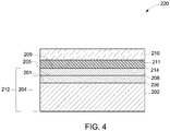
- FIG. 4 shows a sealing structure 220 where the coated ceramic component 212 and the metal component 210 are joined/bonded by brazing, according to one embodiment of the invention.
- a braze material is introduced between a surface 209 of the metallic barrier layer 208 and a surface 211 of the metal component 210.
- a layer 214 of the braze material is disposed on at least the surface 211 or the surface 209 to be joined by brazing.
- the layer 214 of the braze material in a specific embodiment, is disposed on the surface 209 of the barrier layer 208.
- the thickness of the braze material layer 214 may be in a range between about 5 microns to about 100 microns.
- the thickness of the layer 214 ranges from about 10 microns to about 50 microns.
- the layer 214 may be deposited or applied on one or both the surfaces to be joined, by any suitable technique, e.g. by a printing process or other dispensing processes.
- a foil, a wire, or a preform may be suitably positioned for bonding the surfaces to be joined.
- a braze material for a particular application, should withstand the service conditions required, and should melt at a lower temperature than the base materials; or should melt at a very specific temperature.
- the braze material includes a nickel-based alloy or a cobalt-based alloy. In general, the amount of nickel or cobalt balances the respective alloy based on the amounts of the other constituents.
- These braze alloy may further include at least one of chromium, cobalt, iron, nickel, aluminum, gold, tin, zinc, molybdenum, germanium, silicon, boron, or a combination thereof.
- the braze alloy includes up to about 30 weight percent (e.g., about 0.1%-30%) of each of the constituents, based on the total weight of the braze alloy.
- Some non-limiting examples of the braze alloy are Ni-7Cr-3Fe-4.5Si-3.5B, Co-7Cr-3Fe-4.5Si-3.5B, 92.5Ni-4.5Si-3B, 71Ni-19Cr-10Si, 36Ni-34Pd-30Au, and 47Ni-47Pd-6Si.
- the braze alloy has a liquidus temperature lower than the melting temperatures of the components to be joined.
- the braze alloy has a liquidus temperature of at least about 850 degrees Celsius.
- the braze alloy has a liquidus temperature from about 850 degrees Celsius to about 1300 degrees Celsius, and in some specific embodiments, from about 950 degrees Celsius to about 1250 degrees Celsius.
- the braze alloy is heated to a brazing temperature at which the braze alloy melts and flows over the surfaces.
- the brazing temperature is usually higher than the liquidus temperature of the braze alloy.
- the heating can be undertaken in a controlled atmosphere, such as argon, hydrogen, nitrogen, helium; or in a vacuum.
- the alloy is held at the brazing temperature for a few minutes after melting of the alloy.
- the brazing may be carried out at a brazing temperature ranging from about 900 degrees Celsius to about 1200 degrees Celsius for about 1 minute to about 15 minutes. In a specific embodiment, the brazing may be carried out from about 1000 degrees Celsius to about 1100 degrees Celsius for about 5 minutes to about 15 minutes.
- the brazing temperature may be high enough, in some embodiments, to initiate the formation of the intermetallic (e.g., Ni-Mo), the duration of the brazing process (which includes holding the sealing structure at the brazing temperature) should be brief enough to prevent the formation of a significant amount of the intermetallic.
- a small amount of the intermetallic e.g., less than about 20 volume percent may be formed during any heating step of the sealing process, which may have an insignificant effect on the strength of the seal/joint.
- FIG. 5 is a schematic diagram depicting an exemplary embodiment of a sodium-metal halide battery cell 300 that includes a ceramic-to-metal sealing structure as described above.
- the cell 300 has an ion-conductive separator tube 302 disposed in a cell case 304.
- the separator tube 302 is usually made of ⁇ -alumina or ⁇ "-alumina.
- the tube 302 defines an anode chamber 306 between the cell case 304 and the tube 302, and a cathode chamber 310, inside the tube 302.
- the anode chamber 306 usually contains an anode material 308, e.g. sodium.
- the cathode chamber 310 contains a cathode material 312 (e.g. nickel and sodium chloride), and a molten electrolyte, usually sodium chloroaluminate (NaAlCl 4 ).
- An electrically insulating ceramic collar 320 which may be made of alpha-alumina, is situated at a top end 314 of the tube 302.
- a cathode current collector assembly 3 16 is disposed in the cathode chamber 310, with a cap structure 3 1 8 in the top region of the cell.
- the ceramic collar 320 is fitted onto the top end 314 of the separator tube 302, and is sealed by a glass seal 330.
- the collar 320 includes an upper portion 322, and a lower inner portion 324 that abuts against an inner wall of the tube 302, as illustrated in FIG. 5 .
- a metal ring 340 is disposed, covering the alpha alumina collar 320, and joining the collar with the current collector assembly 316, at the cap structure 318.
- the metal ring 340 has two portions; an outer metal ring 342 and an inner metal ring 344, which are joined, respectively, with the upper portion 322 and the lower portion 324 of the ceramic collar 320, through a seal 350.
- the seal 350 is provided by the method of ceramic-to metal joining as described above, and includes a sealing structure (for example, similar to the sealing structure 220 of FIG. 4 ).
- the seal 350 maintains a seal between selected contents of the cell and the environment at the operating temperature of the cell.
- the cell is often operable at a temperature greater than about 100 degrees Celsius. In some embodiments, the operation temperature of the cell ranges from about 300 degrees Celsius to about 500 degrees Celsius.
- the collar 320 and the metal ring 340 may be temporarily held together with an assembly (e.g., a clamp), or by other techniques, until the sealing process is complete.
- the outer metal ring 342 and the inner metal ring 344 are usually welded shut to seal the cell, after joining with the ceramic collar 320 is completed.
- the outer metal ring 342 can be welded to the cell case 304; and the inner metal ring 344 can be welded to the current collector assembly 316.
- each of the terms “collar” and “ring” is meant to comprise metal or ceramic parts of circular or polygonal shape, and in general, all shapes that are compatible with a particular cell design.
- sample 1 and sample 2 samples (sample 1 and sample 2) of alpha alumina collars having molybdenum metallization were taken for analysis.
- the alumina collar has a circular ridge with an outer diameter of 28 mm and a surface area of 150 mm 2 .
- Samples 1 and 2 were respectively plated with nickel and nickel-2% copper by a screen printing technique.
- Nickel screen printing ink having bimodal particle size distribution was obtained from Heraeus.
- 2 weight percent copper was added to the ink.
- the deposition was performed using 325 mesh screen by a DEK Horizon screen printer.
- Each of the plating layers had a thickness of about 15 microns, and a porosity of about 40 percent by volume.
- these samples were sintered at about 850 degrees Celsius for about 15 minutes in an atmosphere of 4 percent hydrogen and balance nitrogen. After sintering, the porosity of the Ni-2%Cu plating layer (sample 2) was less than about 5 percent by volume; and the porosity of Ni plating layer (sample 1) was about 15 percent.
- Each plated sample 1 and 2 was then bonded to a nickel seal ring that matched the size of the ridge on the alumina collar, by brazing.
- a foil of a braze composition Ni-7Cr-4.5Si-3Fe-3.5B was placed between the plated layer and the nickel ring, and heated up to a temperature of about 1055 degrees Celsius. Each sample was hold at about 1055 degrees Celsius for about 15 minutes, in an atmosphere of 4 percent hydrogen and balance nitrogen, to perform brazing.
- the resulting bonded structures 1 and 2 were then subjected to a leak test and subsequently to a peel test. All the parts were found to be hermetic when tested with helium leak rate. A helium leak of less than 4 x 10 -9 millibar ⁇ liter/sec was considered as pass.
- the peel test measures the load required to push apart the nickel seal ring from the bonded surface and is a measure of joint strength. The alumina section of the bonded structures was held in a place, and the nickel section was pushed by a push rod.
- FIG. 6 shows a joint strength plotted with a 2-parameter Weibull, where the y-axis is probability of failure (%) and the x-axis is load-to-failure (N).
- the solid line corresponds to the joint of the structure 2; and the dotted line corresponds to the joint of the structure 1. It is clear from the plot that while, in this instance, the joint of structure 2 (solid line) did not exceed much that of the structure 1 (dotted line), in terms of strength, it was generally as good as the joint of structure 1.
- the present inventors discovered that a satisfactory joint with approximately the same strength of a joint formed by a conventional process can be obtained by using the preferred screen printing process for depositing a Ni-containing plating layer.
Landscapes
- Chemical & Material Sciences (AREA)
- Engineering & Computer Science (AREA)
- Chemical Kinetics & Catalysis (AREA)
- Electrochemistry (AREA)
- General Chemical & Material Sciences (AREA)
- Ceramic Engineering (AREA)
- Mechanical Engineering (AREA)
- Manufacturing & Machinery (AREA)
- Materials Engineering (AREA)
- Structural Engineering (AREA)
- Organic Chemistry (AREA)
- Inorganic Chemistry (AREA)
- Ceramic Products (AREA)
- Secondary Cells (AREA)
Description
- The invention relates generally to a method for joining a ceramic component to a metal component. More particularly, the invention includes embodiments that relate to a ceramic-to-metal joining for sealing a high temperature electrochemical cell. The invention also includes embodiments that relate to a sealing structure formed by using such a method.
-
EP 0 333 149 A2 -
US 2001/036541 A1 discloses placing a ceramic base coated with a metallizing ink in a furnace and sintering at temperatures from 1150 to 1350 °C. -
US5009357 describes a ceramic base that is joined to a Cu component through a Ti foil of 6-25 microns thickness and a Cu-P-Sn-Ni foil of 5-150 microns thickness. The P functions as a melting point depressant and is present in 3 to 10 wt%. The goal is to construct a high temperature electrochemical cell. - Many types of seal joints have been considered for use in high-temperature rechargeable batteries/cells for joining different components. Sodium/sulfur or sodium/metal halide cells generally include several ceramic and metal components. The ceramic components include an electrically insulating alpha-alumina collar and an ion-conductive electrolyte beta-alumina tube, and are generally joined or bonded via a sealing glass. The metal components include a metallic casing, current collector components, and other metallic components which are often joined by welding or thermal compression bonding (TCB).
- A metal-to-ceramic bonding is most critical for the reliability and safety of the cell because it has several issues, mainly due to thermal stress caused by a mismatch in the coefficient of thermal expansion for the ceramic and metal components. Many types of bonding materials and sealing processes have been considered for joining metal components to ceramic components, including ceramic adhesives, brazing, and diffusion bonding. However, most of the seals/joints may not withstand high temperatures and corrosive environments of the batteries/cells.
- Current methods include metalizing the ceramic component, followed by bonding the metallized ceramic component to the metal component by thermal compression bonding. Usually, an outer surface of a metallization layer is further treated by plating the surface with a metal to form a metal layer on the metallization layer, before the metal component is bonded to the ceramic component. The plating layer provides a continuous metal layer on the metallization surface to obtain a high strength joint/bond with the metal component. Usually, although not necessarily, the plating metal is the same metal as that of the metal component, or a metal that is at least compatible with the metal of the metallization layer and with the metal component. For example, nickel has been conventionally used for plating a molybdenum-based metallization layer on alumina, specifically in high temperature batteries/cells.
- Various methods have been used for plating metal (e.g., nickel) on the metallization layer, for example electroplating, electroless plating, screen printing, etc. Each of these processes has one or more issues with respect to the quality of the plating layer or the scalability of the process. Screen printing is a highly scalable, clean and cost effective process, but provides a porous metal layer. The porous plating layer may lead to the contamination of the metallization material which thus affects the strength of the resulting metal-to-ceramic bond/joint. This porous metal layer, for example, nickel layer, can be sintered (treated at high temperatures, e.g., above about 1200 degrees Celsius) for the densification of the layer, but may often form an intermetallic with the metal (e.g., molybdenum) of the metallization layer at high temperatures (usually above 1000 degrees Celsius). The formation of the intermetallic adversely affects the bonding between the plating layer and the metallization layer, and thus the joint/bond between the ceramic component and the metal component.
- With these considerations in mind, it would therefore be desirable to develop new materials and methods for efficient ceramic-to-metal joining. Particularly, it may be desirable to have a method for sealing a high temperature electrochemical cell that differs from those methods that are currently available. It may be desirable to have a sealing structure that uses materials and methods that differ from those materials and methods that are currently available.
- The present disclosure relates to a method and a sealing structure as set forth in the claims.
- These and other features, aspects, and advantages of the present invention will become better understood when the following detailed description is read with reference to the accompanying drawings, in which like characters represent like parts throughout the drawings, wherein:
-
FIG. 1 is a flow diagram illustrating a method for joining a ceramic component to a metal component, in accordance with one embodiment of the invention; -
FIG. 2 is a schematic view of a sealing structure, in accordance with one embodiment of the invention; -
FIG. 3 is a schematic view of a step-wise method for disposing a metallic barrier layer, in accordance with one embodiment of the invention; -
FIG. 4 is a schematic view of a sealing structure, in accordance with another embodiment of the invention; -
FIG. 5 is a schematic view showing a cross-section of an electrochemical cell using a sealing structure, in accordance with one embodiment of the invention; and -
FIG. 6 is a graph showing comparative results of a peel test for two bonded structures. - The embodiments described herein relate to ceramic-to-metal joining. It should be understood that the embodiments are not limited to joining a ceramic component to a metal component for sealing an electrochemical cell/battery, for example sodium/sulfur or sodium metal halide cells, and the descriptions and figures are not limited to electrochemical cells. The embodiments described herein may have various applications, for example, in electronics, where ceramics are used as insulators in circuit boards, and need to be bonded to metals. Another application is in the lighting industry, for example in ceramic metal halide lamps where a metallic feedthrough needs to be bonded to a ceramic discharge chamber of the lamp. Approximating language, as used herein throughout the specification and claims, may be applied to modify any quantitative representation that could permissibly vary, without resulting in a change in the basic function to which it is related. Accordingly, a value modified by a term or terms, such as "about," is not limited to the precise value specified. In some instances, the approximating language may correspond to the precision of an instrument for measuring the value.
- In the following specification and the claims, the singular forms "a", "an" and "the" include plural referents unless the context clearly dictates otherwise. As used herein, the terms "may" and "may be" indicate a possibility of an occurrence within a set of circumstances; a possession of a specified property, characteristic or function; and/or qualify another verb by expressing one or more of an ability, capability, or possibility associated with the qualified verb. Accordingly, usage of "may" and "may be" indicates that a modified term is apparently appropriate, capable, or suitable for an indicated capacity, function, or usage, while taking into account that in some circumstances the modified term may not be appropriate, capable, or suitable. For example, in some circumstances, an event or capacity may be expected, while in other circumstances the event or capacity may not occur.
- The terms "comprising", "including" and "having" are intended to be inclusive, and mean that there may be additional elements other than the listed elements. As used herein, the term "and/or" includes any and all the combinations of one or more of the associated listed items. Unless otherwise indicated herein, the terms "disposed on", "deposited on" or "disposed between" refer to both direct contact between layers, objects, and the like, or indirect contact, e.g., having intervening layers therebetween.
- According to the invention, a method for joining a ceramic component to a metal component is illustrated in
FIG. 1 . The method is highly scalable and cost effective, as compared to prior art methods, and provides a high-strengthhermetic sealing structure 200 as depicted inFIG. 2 . Themethod 100 involves astep 102 of disposing a metallic barrier layer 208 (FIG. 2 ) on a metallized portion of a ceramic component 204 (can also be referred to as "a metallized ceramic component" or "metallized ceramic"), and then astep 104 of bonding ametal component 210 to the metallized portion of theceramic component 204 through themetallic barrier layer 208. Thebarrier layer 208 includes nickel and a melting point depressant. - As illustrated in
Fig. 2 , the metallizedceramic component 204 includes ametallization layer 206 disposed on asurface 201 of aceramic component 202. Themetallization layer 206 is first disposed on a portion of theceramic component 202 followed by the disposition of thebarrier layer 208. As known to those skilled in the art, a metallized ceramic usually enables the bonding of the ceramic with a metal. - In one embodiment, the
ceramic component 202 includes an electrically insulating ceramic. Suitable materials for theceramic component 202 may include alpha-alumina, yttria, zirconia, yttria stabilized zirconia, yttrium aluminum garnet, magnesia alumina spinel, or yttrium aluminate perovskite. In one embodiment, theceramic component 202 includes alpha-alumina. - Suitable metal examples for the
metal component 210 include nickel, iron, copper or a combination thereof. In one embodiment, themetal component 210 includes nickel or a nickel-containing alloy, such as Inconel. In one embodiment, themetal component 210 includes iron or a ferrous alloy, such as Fecralloy. - Metallization, generally, means coating a surface of a substrate (may be non-metallic) with a thin layer of a metal. The thin metal layer need not be continuous. The formation of a metallized ceramic typically includes coating a metal matrix on a portion of a surface of a ceramic, and then sintering the coated ceramic to a high temperature (usually greater than about 1000 degrees Celsius) under a reducing atmosphere in the presence of glass forming constituents that form a glass phase in a resulting metallization layer. In certain embodiments, the metal matrix is sintered in a temperature range from about 1200 degrees Celsius to about 1600 degrees Celsius.
- In some instances, the sintering step results in the migration of a glass phase from the interior of the ceramic to the surface of the ceramic, where it fills the pores of the metal matrix while providing a glass bond to the underlying ceramic. In some other instances, as known to those skilled in the art, the glass forming constituent is provided on the surface of the ceramic prior to the sintering step to form the glass phase in the metallization layer. In some instances, the glass forming constituent can be provided in the metal matrix as described in
U.S. Pub. No. 2011/0244303 . - The
metallization layer 206 includes a refractory metal. The refractory metal includes one or more of molybdenum, tungsten, niobium, and tantalum. In one embodiment, themetallization layer 206 includes molybdenum. The amount of molybdenum may be higher than about 80 weight percent, based on the total weight of the metallization layer. In certain embodiments, the amount of molybdenum is as high as 100 weight percent. Moreover, themetallization layer 206 may be substantially free of manganese. Particularly, in a sodium metal halide cell, manganese is incompatible in the sodium and/or halide environment of the cell. In certain embodiments, themetallization layer 206 may comprise no manganese, or very small amounts of manganese, for example, at impurity levels. - As discussed above, the
metallization layer 206 may further include a glass phase. In some embodiments, the glass phase includes one or more of alpha-alumina, silica, alumina silica, calcia alumina silica, yttria, zirconia, yttria stabilized zirconia, dysprosium oxide, yttrium aluminum garnet, magnesia alumina spinel, or yttrium aluminate perovskite. In one embodiment, the glass phase includes alpha-alumina. - A variety of deposition techniques can be used for metallizing the
ceramic component 202. In one embodiment, a metal matrix is first applied in the form of a layer or a coating on thesurface 201, followed by sintering. The metal matrix can be applied by any suitable deposition technique known in the art. Non-limiting examples of the deposition techniques include a physical vapor deposition technique, screen printing, painting, and sputtering. The painting technique often includes dipping, spraying, ink printing, syringe or nozzle brushing, or tape transfer. In a particular embodiment, it is preferable for some situations that the metal matrix is applied by the screen printing technique. The screen printing technique is preferable here because of its high yield and high manufacturing throughput for a large scale manufacturing. In addition, the process is relatively inexpensive and environmentally friendly, compared to other listed processes. - Before deposition, the
surface 201 of theceramic component 202 may be polished or similarly treated, so as to remove any manufacturing damage and/or to improve the surface flatness. For example, thesurface 201 may be polished to about 15 microns ANSI/CAMI. Theceramic component 202 may further be chemically cleaned prior to the metallization, so as to remove contaminants that may affect bonding. Furthermore, theceramic component 202 may be thermally annealed and/or calcined at an elevated temperature prior to the metallization, so as to reduce contamination, reduce residual stresses, and/or heal defects that may have been introduced into the ceramic components during preparation. However, these steps of polishing, cleaning, annealing and calcining may not be essential for producing high-quality joints; and may be used individually or in combination as per requirement. - Usually, a metallization layer may have a large coefficient of thermal expansion (CTE) mismatch with an underlying ceramic. In various embodiments, the
metallization layer 206 may have a thickness as small as possible from the stress point of view i.e., the CTE mismatch, yet thick enough to have a sufficient glass phase to provide a high enough bonding strength with theceramic component 202. In some embodiments, themetallization layer 206 has a thickness in a range of about 5 microns to about 100 microns. In some embodiments, themetallization layer 206 has a thickness in a range of about 10 microns to about 50 microns, and in some specific embodiments, in a range of about 20 microns to about 40 microns. As mentioned previously, referring toFIGS. 1 and 2 , themetallic barrier layer 208 is disposed, for example, plated on asurface 205 of themetallization layer 206. As used herein, a metallic barrier layer refers to a continuous metallic layer. The roles of themetallic barrier layer 208 are to aid wetting of therefractory metallization layer 206 by a metal or an alloy (for example, a braze alloy) that is compatible with themetal component 210 to be joined to theceramic component 202, and to resist penetration of a bonding material into themetallization layer 206. One key parameter that affects both of these roles is the thickness of thebarrier layer 208. If it is too thin, the bonding material (for example a braze alloy) may seep through to themetallization layer 206, but if it is too thick, blisters may be formed during the bonding process that may lead to poor adherence and leaks in a resulting seal/joint. The thickness of thebarrier layer 208 from 1 micron to 10 microns is sufficient to avoid such problems. In some embodiments, the thickness of thebarrier layer 208 may be between about 2 microns and about 6 microns. - The
metallic barrier layer 208 is deposited by screen printing. As alluded to previously, the screen printing technique is highly scalable because of its various advantages, for example, high speed manufacturing, no waste or byproducts, and environmentally benign. In addition, compared to some of the above listed processes, screen printing is a relatively simple, clean and non-aqueous process inside a manufacturing facility for large scale production of the plated ceramic components. In some instances, the deposition of both themetallization layer 206 and thebarrier layer 208 can be performed by screen printing, and thus the same manufacturing facility can advantageously be used for the deposition of both the layers. Thus some embodiments of the present invention provide a less complex, clean, and cost effective process for ceramic-to-metal joining from the production point of view. - In some embodiments,
FIG. 3 shows sub-steps of the method step 102 (FIG. 1 ) for disposing thebarrier layer 208 on the metallizedceramic component 204. In afirst sub-step 106, the metallizedceramic component 204 is provided. In a secondsub-10 step 108, ametallic layer 207 is deposited on thesurface 205 of themetallization layer 206 by a screen printing process. As known to those skilled in the art, a metal layer deposited by screen printing is usually porous. In some instances, the as depositedmetallic layer 207 has a porosity, such as higher than about 25 percent by volume. In some instances, the porosity of the as-depositedmetallic layer 207 is even higher, such as higher than about 30 percent, and in some specific embodiments, even higher than about 40 percent. In some embodiments, the porosity of the as-depositedmetallic layer 207 is in a range from about 30 percent to about 50 percent (all percentages by volume). After deposition of themetallic layer 207, the method involves asintering step 110 to densify the as-deposited porousmetallic layer 207. The presence of the melting point depressant in themetallic layer 207 enables sintering of the layer at a much lower temperature, namely below 1000 degrees Celsius, as compared to a sintering temperature of a nickel layer (e.g., above about 1300 degrees Celsius). At low sintering temperatures, the formation of the intermetallic (e.g., Ni-Mo) may not occur, or may be substantially less (less than about 20 volume percent, based on the total volume of the metallization layer). Moreover, the formation of the intermetallic can further be limited by the duration for which thesintering step 110 is performed (i.e. the sintering time). - The densification (or the reduction in the porosity) of the
metallic layer 207 may depend on several sintering conditions, for example the sintering temperature, pressure, duration, atmosphere, and multiple sintering steps. The sintering of the porousmetallic layer 207 is carried out at a temperature lower than 1000 degrees Celsius. In some embodiments, themetallic layer 207 is sintered at an even lower temperature, i.e., lower than about 950 degrees Celsius. In some embodiments, the sintering temperature is in a range from about 700 degrees Celsius to about 950 degrees Celsius, and in some specific embodiments, from about 750 degrees Celsius to about 900 degrees Celsius. In some embodiments, thesintering step 110 is performed for less than about 60 minutes, and in some embodiments, from about 15 minutes to about 30 minutes. - As will be appreciated by one of ordinary skill in the art, the
sintering step 110 may include one or more sub-steps, where sintering may be carried out by, for example, using a different temperature, pressure and/or a different environment in one or more of the sub-steps. For example, thesintering step 110 includes a sub-step of heating themetallic layer 207 at about 850 degrees Celsius for about 15 minutes, and then increasing the temperature to about 950 degrees Celsius in next sub-step and then sintering the layer for about 10 minutes. - After sintering, the porosity of the
metallic layer 207 may be significantly reduced. The resulting sintered layer is denser than themetallic layer 207 before thesintering step 110, and provides (i.e., is transformed into) thebarrier layer 208. In one embodiment, thebarrier layer 208 may have lower porosity (higher density) as compared to the high porosity (low density) of the as-depositedmetallic layer 207. In one embodiment, the porosity of thebarrier layer 208 may be reduced to about 1 percent. The porosity of thebarrier layer 208 is lower than 10 percent, and in one specific embodiment, lower than about 5 percent 25 (all percentages by volume). - As discussed above, by optimizing the sintering conditions (temperature and time), a desired densification (i.e., a porosity of about 1 percent by volume) of the
metallic barrier layer 208 can be achieved while preventing/minimizing the formation of the undesirable intermetallic materials. - Non-limiting examples of the melting point depressant may include, but are not limited to, aluminum, copper, germanium, silicon, boron, zirconium, or combinations thereof. In one embodiment, the
barrier layer 208 may include nickel and copper. In one embodiment, the barrier layer may include nickel and germanium. In certain embodiments, an alloy containing nickel, boron, and silicon (e.g., Ni-B-Si based alloy) may be used with nickel metal for thebarrier layer 208. - The amount of the melting point depressant may be sufficient to reduce the melting temperature and thus the sintering temperature of the material, so that the sintering of the
metallic layer 207 can be performed at a much lower temperature as compared to the sintering temperature of a nickel layer. In one embodiment, an amount of the melting point depressant in themetallic barrier layer 208 ranges from about 1 weight percent to about 10 weight percent, based on the total weight of the material. In a specific embodiment, the amount of the melting point depressant ranges from about 2 weight percent to about 6 weight percent, based on the total weight of the material. - After formation of the
metallic barrier layer 208, a coated ceramic component 212 (FIG. 2 ) (that includes themetallization layer 206 and the barrier layer 208) can be bonded to themetal component 210. Various bonding methods may be used for the purpose. Suitable bonding methods may include brazing and diffusion bonding. Diffusion bonding typically involves holding the two components under stress at an elevated temperature - usually in a non-oxidizing atmosphere (e.g., hydrogen, nitrogen, argon) or vacuum. The compressive pressure or stress applied should be kept below the pressure levels which may cause macroscopic deformation of the components. - One embodiment provides brazing the
metal component 210 to the coatedceramic component 212. Typically, "brazing" uses a braze material (usually an alloy) having a lower liquidus temperature than the melting points of the components (i.e. their materials) to be joined. The braze material is brought slightly above its melting temperature (or liquidus temperature) while protected by a suitable atmosphere. The braze material then flows over the surface (known as wetting) of the components to be joined, and is then cooled to join the components together. As used herein, "braze alloy composition" or "braze alloy", "braze material" or "brazing alloy", refers to a composition that has the ability to wet the components to be joined, and to seal them. -
FIG. 4 shows a sealingstructure 220 where the coatedceramic component 212 and themetal component 210 are joined/bonded by brazing, according to one embodiment of the invention. A braze material is introduced between asurface 209 of themetallic barrier layer 208 and asurface 211 of themetal component 210. In one embodiment, alayer 214 of the braze material is disposed on at least thesurface 211 or thesurface 209 to be joined by brazing. Thelayer 214 of the braze material, in a specific embodiment, is disposed on thesurface 209 of thebarrier layer 208. The thickness of thebraze material layer 214 may be in a range between about 5 microns to about 100 microns. In some specific embodiments, the thickness of thelayer 214 ranges from about 10 microns to about 50 microns. Thelayer 214 may be deposited or applied on one or both the surfaces to be joined, by any suitable technique, e.g. by a printing process or other dispensing processes. In some instances, a foil, a wire, or a preform may be suitably positioned for bonding the surfaces to be joined. - A braze material, for a particular application, should withstand the service conditions required, and should melt at a lower temperature than the base materials; or should melt at a very specific temperature. In one embodiment, the braze material includes a nickel-based alloy or a cobalt-based alloy. In general, the amount of nickel or cobalt balances the respective alloy based on the amounts of the other constituents. These braze alloy may further include at least one of chromium, cobalt, iron, nickel, aluminum, gold, tin, zinc, molybdenum, germanium, silicon, boron, or a combination thereof. These constituents may provide adjustments in several required properties of the braze alloy, for example, the coefficient of thermal expansion, the liquidus temperature, the brazing temperature, the corrosion resistance, and the mechanical strength of the braze alloy. With respect to the amount, the braze alloy includes up to about 30 weight percent (e.g., about 0.1%-30%) of each of the constituents, based on the total weight of the braze alloy. Some non-limiting examples of the braze alloy are Ni-7Cr-3Fe-4.5Si-3.5B, Co-7Cr-3Fe-4.5Si-3.5B, 92.5Ni-4.5Si-3B, 71Ni-19Cr-10Si, 36Ni-34Pd-30Au, and 47Ni-47Pd-6Si.
- As discussed previously, the braze alloy has a liquidus temperature lower than the melting temperatures of the components to be joined. In one embodiment, the braze alloy has a liquidus temperature of at least about 850 degrees Celsius. In one embodiment, the braze alloy has a liquidus temperature from about 850 degrees Celsius to about 1300 degrees Celsius, and in some specific embodiments, from about 950 degrees Celsius to about 1250 degrees Celsius.
- For brazing, the braze alloy is heated to a brazing temperature at which the braze alloy melts and flows over the surfaces. The brazing temperature is usually higher than the liquidus temperature of the braze alloy. The heating can be undertaken in a controlled atmosphere, such as argon, hydrogen, nitrogen, helium; or in a vacuum. To achieve good flow and wetting of the braze alloy, the alloy is held at the brazing temperature for a few minutes after melting of the alloy.
- In one embodiment, the brazing may be carried out at a brazing temperature ranging from about 900 degrees Celsius to about 1200 degrees Celsius for about 1 minute to about 15 minutes. In a specific embodiment, the brazing may be carried out from about 1000 degrees Celsius to about 1100 degrees Celsius for about 5 minutes to about 15 minutes.
- Although the brazing temperature may be high enough, in some embodiments, to initiate the formation of the intermetallic (e.g., Ni-Mo), the duration of the brazing process (which includes holding the sealing structure at the brazing temperature) should be brief enough to prevent the formation of a significant amount of the intermetallic. A small amount of the intermetallic (e.g., less than about 20 volume percent) may be formed during any heating step of the sealing process, which may have an insignificant effect on the strength of the seal/joint.
-
FIG. 5 is a schematic diagram depicting an exemplary embodiment of a sodium-metalhalide battery cell 300 that includes a ceramic-to-metal sealing structure as described above. Thecell 300 has an ion-conductive separator tube 302 disposed in acell case 304. Theseparator tube 302 is usually made of β-alumina or β"-alumina. Thetube 302 defines ananode chamber 306 between thecell case 304 and thetube 302, and acathode chamber 310, inside thetube 302. Theanode chamber 306 usually contains ananode material 308, e.g. sodium. Thecathode chamber 310 contains a cathode material 312 (e.g. nickel and sodium chloride), and a molten electrolyte, usually sodium chloroaluminate (NaAlCl4). - An electrically insulating
ceramic collar 320, which may be made of alpha-alumina, is situated at atop end 314 of thetube 302. A cathode current collector assembly 3 16 is disposed in thecathode chamber 310, with a cap structure 3 1 8 in the top region of the cell. Theceramic collar 320 is fitted onto thetop end 314 of theseparator tube 302, and is sealed by aglass seal 330. In one embodiment, thecollar 320 includes anupper portion 322, and a lowerinner portion 324 that abuts against an inner wall of thetube 302, as illustrated inFIG. 5 . - In order to seal the
cell 300 at the top end (i.e., its upper region), and protect thealumina collar 320 in the corrosive environment, ametal ring 340 is disposed, covering thealpha alumina collar 320, and joining the collar with thecurrent collector assembly 316, at thecap structure 318. Themetal ring 340 has two portions; anouter metal ring 342 and aninner metal ring 344, which are joined, respectively, with theupper portion 322 and thelower portion 324 of theceramic collar 320, through aseal 350. Theseal 350 is provided by the method of ceramic-to metal joining as described above, and includes a sealing structure (for example, similar to the sealingstructure 220 ofFIG. 4 ). Theseal 350 maintains a seal between selected contents of the cell and the environment at the operating temperature of the cell. The cell is often operable at a temperature greater than about 100 degrees Celsius. In some embodiments, the operation temperature of the cell ranges from about 300 degrees Celsius to about 500 degrees Celsius. Thecollar 320 and themetal ring 340 may be temporarily held together with an assembly (e.g., a clamp), or by other techniques, until the sealing process is complete. Theouter metal ring 342 and theinner metal ring 344 are usually welded shut to seal the cell, after joining with theceramic collar 320 is completed. Theouter metal ring 342 can be welded to thecell case 304; and theinner metal ring 344 can be welded to thecurrent collector assembly 316. - The shapes and size of the several components discussed above with reference to
FIG. 5 are only illustrative for the understanding of the cell structure; and are not meant to limit the scope of the invention. The exact position of the seals and the joined components can vary to some degree. Moreover, each of the terms "collar" and "ring" is meant to comprise metal or ceramic parts of circular or polygonal shape, and in general, all shapes that are compatible with a particular cell design. - The example that follows is merely illustrative, and should not be construed to be any sort of limitation on the scope of the claimed invention. Unless specified otherwise, all ingredients may be commercially available from such common chemical suppliers as Alpha Aesar, Inc. (Ward Hill, Massachusetts), Sigma Aldrich (St. Louis, Missouri), Spectrum Chemical Mfg. Corp. (Gardena, California), and the like.
- 2 samples (sample 1 and sample 2) of alpha alumina collars having molybdenum metallization were taken for analysis. The alumina collar has a circular ridge with an outer diameter of 28 mm and a surface area of 150 mm2. Samples 1 and 2 were respectively plated with nickel and nickel-2% copper by a screen printing technique. Nickel screen printing ink having bimodal particle size distribution was obtained from Heraeus. For sample 2, 2 weight percent copper was added to the ink. The deposition was performed using 325 mesh screen by a DEK Horizon screen printer. Each of the plating layers had a thickness of about 15 microns, and a porosity of about 40 percent by volume. After deposition, these samples were sintered at about 850 degrees Celsius for about 15 minutes in an atmosphere of 4 percent hydrogen and balance nitrogen. After sintering, the porosity of the Ni-2%Cu plating layer (sample 2) was less than about 5 percent by volume; and the porosity of Ni plating layer (sample 1) was about 15 percent.
- Each plated sample 1 and 2 was then bonded to a nickel seal ring that matched the size of the ridge on the alumina collar, by brazing. A foil of a braze composition Ni-7Cr-4.5Si-3Fe-3.5B was placed between the plated layer and the nickel ring, and heated up to a temperature of about 1055 degrees Celsius. Each sample was hold at about 1055 degrees Celsius for about 15 minutes, in an atmosphere of 4 percent hydrogen and balance nitrogen, to perform brazing.
- The resulting bonded structures 1 and 2, corresponding to samples 1 and 2 respectively, were then subjected to a leak test and subsequently to a peel test. All the parts were found to be hermetic when tested with helium leak rate. A helium leak of less than 4 x 10⁻⁹ millibar·liter/sec was considered as pass. The peel test measures the load required to push apart the nickel seal ring from the bonded surface and is a measure of joint strength. The alumina section of the bonded structures was held in a place, and the nickel section was pushed by a push rod.
FIG. 6 shows a joint strength plotted with a 2-parameter Weibull, where the y-axis is probability of failure (%) and the x-axis is load-to-failure (N). The solid line corresponds to the joint of the structure 2; and the dotted line corresponds to the joint of the structure 1. It is clear from the plot that while, in this instance, the joint of structure 2 (solid line) did not exceed much that of the structure 1 (dotted line), in terms of strength, it was generally as good as the joint of structure 1. It may also be possible to increase the strength of the joint by various adjustments, e.g., by optimizing the content of copper and the particle size distribution in the Ni-Cu material, or by adjusting the plating thickness and the sintering conditions for achieving a dense nickel-containing plating layer to be bonded to the nickel ring. Thus, the present inventors discovered that a satisfactory joint with approximately the same strength of a joint formed by a conventional process can be obtained by using the preferred screen printing process for depositing a Ni-containing plating layer.
Claims (9)
- A method of joining a metal component (210) to a metallized portion of a ceramic component (204), the method comprising:providing the metallized portion of the ceramic component, wherein the metallized portion of the ceramic component (204) comprises a metallization layer (206) comprising titanium, tantalum, vanadium, tungsten, molybdenum or combinations thereof,disposing a metallic barrier layer (208) on a metallized portion of a ceramic component (204), wherein the metallic barrier layer (208) comprises nickel and a melting point depressant; andjoining a metal component (210) to the metallized portion of the ceramic component (204) through the metallic barrier layer (208),characterized in that disposing the metallic barrier layer (208) comprises disposing a metallic layer (207) by a screen printing process and sintering the metallic layer at a temperature below 1000 degrees Celsius so as to dispose a metallic barrier layer of a thickness from 1 micron to 10 microns and a porosity less than 10 percent by volume after sintering.
- The method of claim 1, wherein joining the metal component (210) to the metallized portion of the ceramic component (204) through the metallic barrier layer (208) comprises introducing a braze material (214) between a surface (209) of the metallic barrier layer (208) and a surface (211) of the metal component (210).
- The method of any preceding claim, wherein the ceramic component (204) comprises alpha alumina and the metal component (210) comprises nickel or an alloy thereof.
- The method of any of claims 1 to 3, wherein the melting point depressant comprises copper, silicon, germanium, boron, aluminum, zirconium, or combinations thereof.
- The method of any of claims 1 to 4, wherein an amount of the melting point depressant in the metallic barrier layer (208) ranges from 1 weight percent to 10 weight percent.
- The method of any preceding claim, wherein the metallic layer (207) has a porosity higher than 25 percent by volume.
- The method of any preceding claim, wherein sintering is carried out in a temperature range from 700 degrees Celsius to 950 degrees Celsius.
- The method of any preceding claim, wherein the metallization layer includes a glass phase.
- The method of the preceding claim, wherein the glass phase includes one or more of alpha-alumina, silica, alumina silica, calcia alumina silica, yttria, zirconia, yttria stabilized zirconia, dysprosium oxide, yttrium aluminum garnet, magnesia alumina spinel, or yttrium aluminate perovskite.
Applications Claiming Priority (1)
| Application Number | Priority Date | Filing Date | Title |
|---|---|---|---|
| IN2568CH2014 | 2014-05-23 |
Publications (2)
| Publication Number | Publication Date |
|---|---|
| EP2947062A1 EP2947062A1 (en) | 2015-11-25 |
| EP2947062B1 true EP2947062B1 (en) | 2021-02-17 |
Family
ID=53268678
Family Applications (1)
| Application Number | Title | Priority Date | Filing Date |
|---|---|---|---|
| EP15168809.0A Active EP2947062B1 (en) | 2014-05-23 | 2015-05-22 | Method for joining ceramic to metal |
Country Status (5)
| Country | Link |
|---|---|
| US (1) | US10103410B2 (en) |
| EP (1) | EP2947062B1 (en) |
| JP (1) | JP6480806B2 (en) |
| KR (1) | KR102398188B1 (en) |
| CN (1) | CN105130486A (en) |
Families Citing this family (17)
| Publication number | Priority date | Publication date | Assignee | Title |
|---|---|---|---|---|
| EP3154729A4 (en) * | 2014-06-12 | 2018-02-28 | Alpha Metals, Inc. | Sintering materials and attachment methods using same |
| US10541391B2 (en) * | 2015-09-30 | 2020-01-21 | Apple Inc. | Electrical feedthroughs for battery housings |
| CN105514470A (en) * | 2015-12-14 | 2016-04-20 | 东莞新能源科技有限公司 | Cathode pole piece and lithium ion cell using the pole piece |
| CN105384457B (en) * | 2015-12-15 | 2018-09-07 | 深圳市日联科技有限公司 | A kind of welding method of aluminium oxide ceramics and metal molybdenum |
| CN107234309B (en) * | 2017-04-24 | 2021-01-26 | 广东威特真空电子制造有限公司 | Metallized ceramic structure for brazing, manufacturing method thereof and magnetron |
| CN107342377A (en) * | 2017-07-20 | 2017-11-10 | 东莞威胜储能技术有限公司 | A kind of high temperature battery |
| CN108194730A (en) * | 2018-02-27 | 2018-06-22 | 苏州宝骅密封科技股份有限公司 | A kind of insulated enclosure gasket |
| JP2021518636A (en) * | 2018-03-20 | 2021-08-02 | インディアン・スペース・リサーチ・オーガニゼイションIndian Space Research Organisation | Sealed lithium-ion battery and its manufacturing method |
| CN109108417B (en) * | 2018-09-28 | 2021-07-23 | 西安航空学院 | A welding method of aluminum silicon carbide ceramic substrate based on PVD coating |
| KR102201500B1 (en) | 2018-12-13 | 2021-01-13 | 주식회사 케이씨씨 | Ceramic housing and plating method of ceramic material |
| WO2020260099A1 (en) * | 2019-06-22 | 2020-12-30 | Schott Ag | Compact sensor component for harsh environments |
| US11583960B2 (en) * | 2019-09-25 | 2023-02-21 | Morgan Advanced Ceramics, Inc. | High temperature capable braze assembly |
| GB202001162D0 (en) * | 2020-01-28 | 2020-03-11 | Morgan Advanced Ceramics Inc | High Temperature capable and thermal shock resistant braze assembly |
| KR102667435B1 (en) * | 2020-08-14 | 2024-05-21 | 주식회사 피엠모터스 | Heat Dissipating Device For Battery Pack And Method Of Manufacturing The Same |
| CN112170852A (en) * | 2020-09-30 | 2021-01-05 | 武汉理工大学 | Metal/ceramic/metal sealing insulating material with symmetrical gradient structure and preparation method thereof |
| CN115124362B (en) * | 2022-06-20 | 2023-07-18 | 昆明冶金研究院有限公司北京分公司 | Ceramic copper clad laminate and preparation method thereof |
| CN116903397A (en) * | 2023-07-13 | 2023-10-20 | 陕西宝光陶瓷科技有限公司 | Yttrium aluminum garnet high-density transparent ceramic metallized material and preparation method and application thereof |
Citations (2)
| Publication number | Priority date | Publication date | Assignee | Title |
|---|---|---|---|---|
| US5009357A (en) * | 1988-07-28 | 1991-04-23 | Lilliwyte Societe Anonyme | Joining of ceramic components to metal components |
| EP3041042A1 (en) * | 2013-08-26 | 2016-07-06 | Mitsubishi Materials Corporation | Method for manufacturing assembly and method for manufacturing power-module substrate |
Family Cites Families (24)
| Publication number | Priority date | Publication date | Assignee | Title |
|---|---|---|---|---|
| US4016447A (en) | 1974-11-13 | 1977-04-05 | E. I. Du Pont De Nemours And Company | Dielectric substrate bearing nickel boride conductor |
| CH594972A5 (en) * | 1975-05-28 | 1978-01-31 | Bbc Brown Boveri & Cie | |
| US4064310A (en) | 1977-03-07 | 1977-12-20 | E. I. Du Pont De Nemours And Company | Conductor compositions |
| JPS5780656A (en) * | 1980-11-08 | 1982-05-20 | Hitachi Maxell Ltd | Thin battery |
| DE3537161C2 (en) | 1985-10-18 | 1995-08-03 | Bosch Gmbh Robert | Process for producing firmly adhering, solderable and structurable metal layers on alumina-containing ceramic |
| US4861641A (en) | 1987-05-22 | 1989-08-29 | Ceramics Process Systems Corporation | Substrates with dense metal vias |
| JPH0686340B2 (en) | 1988-01-16 | 1994-11-02 | 長崎県 | Method of joining solid metal and ceramics |
| EP0333149A3 (en) * | 1988-03-17 | 1990-02-28 | Hitachi, Ltd. | Ceramic composite and method of preparation thereof |
| JPH02252665A (en) * | 1988-12-05 | 1990-10-11 | Fujitsu Ltd | Method for soldering |
| JP2650460B2 (en) | 1990-04-12 | 1997-09-03 | 富士電機株式会社 | Joining method of alumina ceramic and metal |
| US5033666A (en) | 1990-04-12 | 1991-07-23 | E. I. Du Pont De Nemours And Company | Process for brazing metallized components to ceramic substrates |
| JP3176015B2 (en) * | 1994-12-06 | 2001-06-11 | 日本特殊陶業株式会社 | Joint of ceramic and metal |
| JP4342084B2 (en) * | 2000-05-30 | 2009-10-14 | 日本特殊陶業株式会社 | Method of manufacturing ceramic member for bonding, ceramic member for bonding, bonded body, vacuum switch, and vacuum container |
| EP1120386B1 (en) * | 2000-01-26 | 2004-04-07 | Ngk Spark Plug Co., Ltd | Metallized ceramic member, process for producing the same, vacuum switch, and vacuum vessel |
| JP3875613B2 (en) * | 2001-10-05 | 2007-01-31 | 日本特殊陶業株式会社 | Method of manufacturing ceramic member for bonding, ceramic member for bonding, vacuum switch, and vacuum vessel |
| US20090061309A1 (en) * | 2006-01-30 | 2009-03-05 | Kyocera Corporation | Container for Electric Energy Storage Device, and Battery and Electric Double Layer Capacitor Using the Same |
| JP2009013490A (en) * | 2007-07-09 | 2009-01-22 | Sumitomo Metal Mining Co Ltd | Nickel powder and method for producing the same |
| CN101104567B (en) | 2007-07-25 | 2010-09-15 | 浙江亚通金属陶瓷有限公司 | Metal composite layer on aluminum oxide ceramic surface and composite technique thereof |
| CH700774A1 (en) * | 2009-03-31 | 2010-10-15 | Alstom Technology Ltd | Doppellotelement, process for its preparation and uses thereof. |
| US20110244303A1 (en) | 2010-04-02 | 2011-10-06 | General Electric Company | Metalized Ceramic and Associated Method |
| US8852786B2 (en) | 2010-12-22 | 2014-10-07 | General Electric Company | Ceramic-metal sealing structure, and associated method |
| US20130224561A1 (en) * | 2012-02-29 | 2013-08-29 | General Electric Company | Braze compositions, and related articles and methods |
| US10105795B2 (en) * | 2012-05-25 | 2018-10-23 | General Electric Company | Braze compositions, and related devices |
| US9548518B2 (en) * | 2014-12-16 | 2017-01-17 | General Electric Company | Methods for joining ceramic and metallic structures |
-
2015
- 2015-05-19 JP JP2015101614A patent/JP6480806B2/en active Active
- 2015-05-22 EP EP15168809.0A patent/EP2947062B1/en active Active
- 2015-05-22 US US14/719,742 patent/US10103410B2/en active Active
- 2015-05-22 CN CN201510470300.0A patent/CN105130486A/en active Pending
- 2015-05-22 KR KR1020150072036A patent/KR102398188B1/en active Active
Patent Citations (2)
| Publication number | Priority date | Publication date | Assignee | Title |
|---|---|---|---|---|
| US5009357A (en) * | 1988-07-28 | 1991-04-23 | Lilliwyte Societe Anonyme | Joining of ceramic components to metal components |
| EP3041042A1 (en) * | 2013-08-26 | 2016-07-06 | Mitsubishi Materials Corporation | Method for manufacturing assembly and method for manufacturing power-module substrate |
Also Published As
| Publication number | Publication date |
|---|---|
| CN105130486A (en) | 2015-12-09 |
| JP6480806B2 (en) | 2019-03-13 |
| KR102398188B1 (en) | 2022-05-17 |
| EP2947062A1 (en) | 2015-11-25 |
| US20150340742A1 (en) | 2015-11-26 |
| KR20150135155A (en) | 2015-12-02 |
| US10103410B2 (en) | 2018-10-16 |
| JP2016028001A (en) | 2016-02-25 |
Similar Documents
| Publication | Publication Date | Title |
|---|---|---|
| US10103410B2 (en) | Method for joining ceramic to metal, and sealing structure thereof | |
| EP2666581B1 (en) | Braze compositions, and related devices | |
| US9548518B2 (en) | Methods for joining ceramic and metallic structures | |
| US7758970B2 (en) | Different materials bonded member and production method thereof | |
| US12397379B2 (en) | Nickel-carbon and nickel-cobalt-carbon brazes and brazing processes for joining ceramics and metals and semiconductor processing and industrial equipment using same | |
| US20110244303A1 (en) | Metalized Ceramic and Associated Method | |
| EP1824630A1 (en) | Braze system with matched coefficients of thermal expansion | |
| US20130224561A1 (en) | Braze compositions, and related articles and methods | |
| US20070119907A1 (en) | Process for producing composite body | |
| US8757471B2 (en) | Active braze techniques on beta-alumina | |
| US20140356681A1 (en) | Brazing structure, and related processes and devices | |
| US20100316885A1 (en) | Assembly method by reactive brazing and vacuum cartridge assembled according to this method | |
| US20060172141A1 (en) | Joints and methods of making and using | |
| US20170043424A1 (en) | Process for joining metallic and ceramic structures | |
| US11123957B2 (en) | High temperature capable and thermal shock resistant brazed article | |
| US20140069988A1 (en) | Methods of using active braze techniques for making high temperature rechargeable batteries | |
| EP3225352B1 (en) | Eutectic brazing compositions, and related processes and devices | |
| US20050092818A1 (en) | High temperature seal for joining ceramic components such as cells in a ceramic oxygen generator | |
| NICHOLAS | Materials Development Division, Harwell Laboratory. |
Legal Events
| Date | Code | Title | Description |
|---|---|---|---|
| PUAI | Public reference made under article 153(3) epc to a published international application that has entered the european phase |
Free format text: ORIGINAL CODE: 0009012 |
|
| AK | Designated contracting states |
Kind code of ref document: A1 Designated state(s): AL AT BE BG CH CY CZ DE DK EE ES FI FR GB GR HR HU IE IS IT LI LT LU LV MC MK MT NL NO PL PT RO RS SE SI SK SM TR |
|
| AX | Request for extension of the european patent |
Extension state: BA ME |
|
| 17P | Request for examination filed |
Effective date: 20160525 |
|
| RBV | Designated contracting states (corrected) |
Designated state(s): AL AT BE BG CH CY CZ DE DK EE ES FI FR GB GR HR HU IE IS IT LI LT LU LV MC MK MT NL NO PL PT RO RS SE SI SK SM TR |
|
| STAA | Information on the status of an ep patent application or granted ep patent |
Free format text: STATUS: REQUEST FOR EXAMINATION WAS MADE |
|
| R17P | Request for examination filed (corrected) |
Effective date: 20160525 |
|
| STAA | Information on the status of an ep patent application or granted ep patent |
Free format text: STATUS: EXAMINATION IS IN PROGRESS |
|
| 17Q | First examination report despatched |
Effective date: 20180326 |
|
| GRAP | Despatch of communication of intention to grant a patent |
Free format text: ORIGINAL CODE: EPIDOSNIGR1 |
|
| STAA | Information on the status of an ep patent application or granted ep patent |
Free format text: STATUS: GRANT OF PATENT IS INTENDED |
|
| RIC1 | Information provided on ipc code assigned before grant |
Ipc: H01M 2/08 20060101ALI20200902BHEP Ipc: H01M 10/39 20060101ALI20200902BHEP Ipc: B23K 35/30 20060101ALI20200902BHEP Ipc: C04B 37/02 20060101AFI20200902BHEP |
|
| INTG | Intention to grant announced |
Effective date: 20200917 |
|
| GRAS | Grant fee paid |
Free format text: ORIGINAL CODE: EPIDOSNIGR3 |
|
| GRAA | (expected) grant |
Free format text: ORIGINAL CODE: 0009210 |
|
| STAA | Information on the status of an ep patent application or granted ep patent |
Free format text: STATUS: THE PATENT HAS BEEN GRANTED |
|
| AK | Designated contracting states |
Kind code of ref document: B1 Designated state(s): AL AT BE BG CH CY CZ DE DK EE ES FI FR GB GR HR HU IE IS IT LI LT LU LV MC MK MT NL NO PL PT RO RS SE SI SK SM TR |
|
| REG | Reference to a national code |
Ref country code: GB Ref legal event code: FG4D |
|
| REG | Reference to a national code |
Ref country code: CH Ref legal event code: EP |
|
| REG | Reference to a national code |
Ref country code: DE Ref legal event code: R096 Ref document number: 602015065492 Country of ref document: DE |
|
| REG | Reference to a national code |
Ref country code: AT Ref legal event code: REF Ref document number: 1361261 Country of ref document: AT Kind code of ref document: T Effective date: 20210315 |
|
| REG | Reference to a national code |
Ref country code: IE Ref legal event code: FG4D |
|
| REG | Reference to a national code |
Ref country code: LT Ref legal event code: MG9D |
|
| REG | Reference to a national code |
Ref country code: NL Ref legal event code: MP Effective date: 20210217 |
|
| PG25 | Lapsed in a contracting state [announced via postgrant information from national office to epo] |
Ref country code: PT Free format text: LAPSE BECAUSE OF FAILURE TO SUBMIT A TRANSLATION OF THE DESCRIPTION OR TO PAY THE FEE WITHIN THE PRESCRIBED TIME-LIMIT Effective date: 20210617 Ref country code: LT Free format text: LAPSE BECAUSE OF FAILURE TO SUBMIT A TRANSLATION OF THE DESCRIPTION OR TO PAY THE FEE WITHIN THE PRESCRIBED TIME-LIMIT Effective date: 20210217 Ref country code: FI Free format text: LAPSE BECAUSE OF FAILURE TO SUBMIT A TRANSLATION OF THE DESCRIPTION OR TO PAY THE FEE WITHIN THE PRESCRIBED TIME-LIMIT Effective date: 20210217 Ref country code: HR Free format text: LAPSE BECAUSE OF FAILURE TO SUBMIT A TRANSLATION OF THE DESCRIPTION OR TO PAY THE FEE WITHIN THE PRESCRIBED TIME-LIMIT Effective date: 20210217 Ref country code: GR Free format text: LAPSE BECAUSE OF FAILURE TO SUBMIT A TRANSLATION OF THE DESCRIPTION OR TO PAY THE FEE WITHIN THE PRESCRIBED TIME-LIMIT Effective date: 20210518 Ref country code: BG Free format text: LAPSE BECAUSE OF FAILURE TO SUBMIT A TRANSLATION OF THE DESCRIPTION OR TO PAY THE FEE WITHIN THE PRESCRIBED TIME-LIMIT Effective date: 20210517 Ref country code: NO Free format text: LAPSE BECAUSE OF FAILURE TO SUBMIT A TRANSLATION OF THE DESCRIPTION OR TO PAY THE FEE WITHIN THE PRESCRIBED TIME-LIMIT Effective date: 20210517 |
|
| REG | Reference to a national code |
Ref country code: AT Ref legal event code: MK05 Ref document number: 1361261 Country of ref document: AT Kind code of ref document: T Effective date: 20210217 |
|
| PG25 | Lapsed in a contracting state [announced via postgrant information from national office to epo] |
Ref country code: RS Free format text: LAPSE BECAUSE OF FAILURE TO SUBMIT A TRANSLATION OF THE DESCRIPTION OR TO PAY THE FEE WITHIN THE PRESCRIBED TIME-LIMIT Effective date: 20210217 Ref country code: LV Free format text: LAPSE BECAUSE OF FAILURE TO SUBMIT A TRANSLATION OF THE DESCRIPTION OR TO PAY THE FEE WITHIN THE PRESCRIBED TIME-LIMIT Effective date: 20210217 Ref country code: PL Free format text: LAPSE BECAUSE OF FAILURE TO SUBMIT A TRANSLATION OF THE DESCRIPTION OR TO PAY THE FEE WITHIN THE PRESCRIBED TIME-LIMIT Effective date: 20210217 Ref country code: NL Free format text: LAPSE BECAUSE OF FAILURE TO SUBMIT A TRANSLATION OF THE DESCRIPTION OR TO PAY THE FEE WITHIN THE PRESCRIBED TIME-LIMIT Effective date: 20210217 Ref country code: SE Free format text: LAPSE BECAUSE OF FAILURE TO SUBMIT A TRANSLATION OF THE DESCRIPTION OR TO PAY THE FEE WITHIN THE PRESCRIBED TIME-LIMIT Effective date: 20210217 |
|
| PG25 | Lapsed in a contracting state [announced via postgrant information from national office to epo] |
Ref country code: IS Free format text: LAPSE BECAUSE OF FAILURE TO SUBMIT A TRANSLATION OF THE DESCRIPTION OR TO PAY THE FEE WITHIN THE PRESCRIBED TIME-LIMIT Effective date: 20210617 |
|
| PG25 | Lapsed in a contracting state [announced via postgrant information from national office to epo] |
Ref country code: EE Free format text: LAPSE BECAUSE OF FAILURE TO SUBMIT A TRANSLATION OF THE DESCRIPTION OR TO PAY THE FEE WITHIN THE PRESCRIBED TIME-LIMIT Effective date: 20210217 Ref country code: CZ Free format text: LAPSE BECAUSE OF FAILURE TO SUBMIT A TRANSLATION OF THE DESCRIPTION OR TO PAY THE FEE WITHIN THE PRESCRIBED TIME-LIMIT Effective date: 20210217 Ref country code: AT Free format text: LAPSE BECAUSE OF FAILURE TO SUBMIT A TRANSLATION OF THE DESCRIPTION OR TO PAY THE FEE WITHIN THE PRESCRIBED TIME-LIMIT Effective date: 20210217 Ref country code: SM Free format text: LAPSE BECAUSE OF FAILURE TO SUBMIT A TRANSLATION OF THE DESCRIPTION OR TO PAY THE FEE WITHIN THE PRESCRIBED TIME-LIMIT Effective date: 20210217 |
|
| REG | Reference to a national code |
Ref country code: DE Ref legal event code: R097 Ref document number: 602015065492 Country of ref document: DE |
|
| PG25 | Lapsed in a contracting state [announced via postgrant information from national office to epo] |
Ref country code: DK Free format text: LAPSE BECAUSE OF FAILURE TO SUBMIT A TRANSLATION OF THE DESCRIPTION OR TO PAY THE FEE WITHIN THE PRESCRIBED TIME-LIMIT Effective date: 20210217 Ref country code: ES Free format text: LAPSE BECAUSE OF FAILURE TO SUBMIT A TRANSLATION OF THE DESCRIPTION OR TO PAY THE FEE WITHIN THE PRESCRIBED TIME-LIMIT Effective date: 20210217 Ref country code: RO Free format text: LAPSE BECAUSE OF FAILURE TO SUBMIT A TRANSLATION OF THE DESCRIPTION OR TO PAY THE FEE WITHIN THE PRESCRIBED TIME-LIMIT Effective date: 20210217 Ref country code: SK Free format text: LAPSE BECAUSE OF FAILURE TO SUBMIT A TRANSLATION OF THE DESCRIPTION OR TO PAY THE FEE WITHIN THE PRESCRIBED TIME-LIMIT Effective date: 20210217 |
|
| PLBE | No opposition filed within time limit |
Free format text: ORIGINAL CODE: 0009261 |
|
| STAA | Information on the status of an ep patent application or granted ep patent |
Free format text: STATUS: NO OPPOSITION FILED WITHIN TIME LIMIT |
|
| REG | Reference to a national code |
Ref country code: CH Ref legal event code: PL |
|
| 26N | No opposition filed |
Effective date: 20211118 |
|
| PG25 | Lapsed in a contracting state [announced via postgrant information from national office to epo] |
Ref country code: CH Free format text: LAPSE BECAUSE OF NON-PAYMENT OF DUE FEES Effective date: 20210531 Ref country code: AL Free format text: LAPSE BECAUSE OF FAILURE TO SUBMIT A TRANSLATION OF THE DESCRIPTION OR TO PAY THE FEE WITHIN THE PRESCRIBED TIME-LIMIT Effective date: 20210217 Ref country code: LU Free format text: LAPSE BECAUSE OF NON-PAYMENT OF DUE FEES Effective date: 20210522 Ref country code: LI Free format text: LAPSE BECAUSE OF NON-PAYMENT OF DUE FEES Effective date: 20210531 Ref country code: MC Free format text: LAPSE BECAUSE OF FAILURE TO SUBMIT A TRANSLATION OF THE DESCRIPTION OR TO PAY THE FEE WITHIN THE PRESCRIBED TIME-LIMIT Effective date: 20210217 |
|
| REG | Reference to a national code |
Ref country code: BE Ref legal event code: MM Effective date: 20210531 |
|
| PG25 | Lapsed in a contracting state [announced via postgrant information from national office to epo] |
Ref country code: SI Free format text: LAPSE BECAUSE OF FAILURE TO SUBMIT A TRANSLATION OF THE DESCRIPTION OR TO PAY THE FEE WITHIN THE PRESCRIBED TIME-LIMIT Effective date: 20210217 |
|
| PG25 | Lapsed in a contracting state [announced via postgrant information from national office to epo] |
Ref country code: IE Free format text: LAPSE BECAUSE OF NON-PAYMENT OF DUE FEES Effective date: 20210522 |
|
| PG25 | Lapsed in a contracting state [announced via postgrant information from national office to epo] |
Ref country code: IS Free format text: LAPSE BECAUSE OF FAILURE TO SUBMIT A TRANSLATION OF THE DESCRIPTION OR TO PAY THE FEE WITHIN THE PRESCRIBED TIME-LIMIT Effective date: 20210617 |
|
| PG25 | Lapsed in a contracting state [announced via postgrant information from national office to epo] |
Ref country code: BE Free format text: LAPSE BECAUSE OF NON-PAYMENT OF DUE FEES Effective date: 20210531 |
|
| PG25 | Lapsed in a contracting state [announced via postgrant information from national office to epo] |
Ref country code: HU Free format text: LAPSE BECAUSE OF FAILURE TO SUBMIT A TRANSLATION OF THE DESCRIPTION OR TO PAY THE FEE WITHIN THE PRESCRIBED TIME-LIMIT; INVALID AB INITIO Effective date: 20150522 |
|
| PG25 | Lapsed in a contracting state [announced via postgrant information from national office to epo] |
Ref country code: CY Free format text: LAPSE BECAUSE OF FAILURE TO SUBMIT A TRANSLATION OF THE DESCRIPTION OR TO PAY THE FEE WITHIN THE PRESCRIBED TIME-LIMIT Effective date: 20210217 |
|
| P01 | Opt-out of the competence of the unified patent court (upc) registered |
Effective date: 20230528 |
|
| PG25 | Lapsed in a contracting state [announced via postgrant information from national office to epo] |
Ref country code: MK Free format text: LAPSE BECAUSE OF FAILURE TO SUBMIT A TRANSLATION OF THE DESCRIPTION OR TO PAY THE FEE WITHIN THE PRESCRIBED TIME-LIMIT Effective date: 20210217 |
|
| PG25 | Lapsed in a contracting state [announced via postgrant information from national office to epo] |
Ref country code: MT Free format text: LAPSE BECAUSE OF FAILURE TO SUBMIT A TRANSLATION OF THE DESCRIPTION OR TO PAY THE FEE WITHIN THE PRESCRIBED TIME-LIMIT Effective date: 20210217 |
|
| PGFP | Annual fee paid to national office [announced via postgrant information from national office to epo] |
Ref country code: DE Payment date: 20250529 Year of fee payment: 11 |
|
| PGFP | Annual fee paid to national office [announced via postgrant information from national office to epo] |
Ref country code: IT Payment date: 20250521 Year of fee payment: 11 |
|
| PGFP | Annual fee paid to national office [announced via postgrant information from national office to epo] |
Ref country code: FR Payment date: 20250526 Year of fee payment: 11 |
|
| PG25 | Lapsed in a contracting state [announced via postgrant information from national office to epo] |
Ref country code: TR Free format text: LAPSE BECAUSE OF FAILURE TO SUBMIT A TRANSLATION OF THE DESCRIPTION OR TO PAY THE FEE WITHIN THE PRESCRIBED TIME-LIMIT Effective date: 20210217 |
|
| PGFP | Annual fee paid to national office [announced via postgrant information from national office to epo] |
Ref country code: GB Payment date: 20260327 Year of fee payment: 12 |