EP2946924A1 - Sandwichbauteil sowie verfahren zur herstellung eines sandwichbauteils - Google Patents
Sandwichbauteil sowie verfahren zur herstellung eines sandwichbauteils Download PDFInfo
- Publication number
- EP2946924A1 EP2946924A1 EP15001549.3A EP15001549A EP2946924A1 EP 2946924 A1 EP2946924 A1 EP 2946924A1 EP 15001549 A EP15001549 A EP 15001549A EP 2946924 A1 EP2946924 A1 EP 2946924A1
- Authority
- EP
- European Patent Office
- Prior art keywords
- core
- solvent
- layers
- thermoplastic material
- sandwich component
- Prior art date
- Legal status (The legal status is an assumption and is not a legal conclusion. Google has not performed a legal analysis and makes no representation as to the accuracy of the status listed.)
- Granted
Links
Images


Classifications
-
- B—PERFORMING OPERATIONS; TRANSPORTING
- B32—LAYERED PRODUCTS
- B32B—LAYERED PRODUCTS, i.e. PRODUCTS BUILT-UP OF STRATA OF FLAT OR NON-FLAT, e.g. CELLULAR OR HONEYCOMB, FORM
- B32B3/00—Layered products comprising a layer with external or internal discontinuities or unevennesses, or a layer of non-planar shape; Layered products comprising a layer having particular features of form
- B32B3/10—Layered products comprising a layer with external or internal discontinuities or unevennesses, or a layer of non-planar shape; Layered products comprising a layer having particular features of form characterised by a discontinuous layer, i.e. formed of separate pieces of material
- B32B3/12—Layered products comprising a layer with external or internal discontinuities or unevennesses, or a layer of non-planar shape; Layered products comprising a layer having particular features of form characterised by a discontinuous layer, i.e. formed of separate pieces of material characterised by a layer of regularly- arranged cells, e.g. a honeycomb structure
-
- B—PERFORMING OPERATIONS; TRANSPORTING
- B29—WORKING OF PLASTICS; WORKING OF SUBSTANCES IN A PLASTIC STATE IN GENERAL
- B29B—PREPARATION OR PRETREATMENT OF THE MATERIAL TO BE SHAPED; MAKING GRANULES OR PREFORMS; RECOVERY OF PLASTICS OR OTHER CONSTITUENTS OF WASTE MATERIAL CONTAINING PLASTICS
- B29B11/00—Making preforms
- B29B11/04—Making preforms by assembling preformed material
-
- B—PERFORMING OPERATIONS; TRANSPORTING
- B29—WORKING OF PLASTICS; WORKING OF SUBSTANCES IN A PLASTIC STATE IN GENERAL
- B29B—PREPARATION OR PRETREATMENT OF THE MATERIAL TO BE SHAPED; MAKING GRANULES OR PREFORMS; RECOVERY OF PLASTICS OR OTHER CONSTITUENTS OF WASTE MATERIAL CONTAINING PLASTICS
- B29B11/00—Making preforms
- B29B11/14—Making preforms characterised by structure or composition
-
- B—PERFORMING OPERATIONS; TRANSPORTING
- B29—WORKING OF PLASTICS; WORKING OF SUBSTANCES IN A PLASTIC STATE IN GENERAL
- B29C—SHAPING OR JOINING OF PLASTICS; SHAPING OF MATERIAL IN A PLASTIC STATE, NOT OTHERWISE PROVIDED FOR; AFTER-TREATMENT OF THE SHAPED PRODUCTS, e.g. REPAIRING
- B29C49/00—Blow-moulding, i.e. blowing a preform or parison to a desired shape within a mould; Apparatus therefor
- B29C49/071—Preforms or parisons characterised by their configuration, e.g. geometry, dimensions or physical properties
-
- B—PERFORMING OPERATIONS; TRANSPORTING
- B32—LAYERED PRODUCTS
- B32B—LAYERED PRODUCTS, i.e. PRODUCTS BUILT-UP OF STRATA OF FLAT OR NON-FLAT, e.g. CELLULAR OR HONEYCOMB, FORM
- B32B27/00—Layered products comprising a layer of synthetic resin
- B32B27/04—Layered products comprising a layer of synthetic resin as impregnant, bonding, or embedding substance
-
- B—PERFORMING OPERATIONS; TRANSPORTING
- B32—LAYERED PRODUCTS
- B32B—LAYERED PRODUCTS, i.e. PRODUCTS BUILT-UP OF STRATA OF FLAT OR NON-FLAT, e.g. CELLULAR OR HONEYCOMB, FORM
- B32B27/00—Layered products comprising a layer of synthetic resin
- B32B27/06—Layered products comprising a layer of synthetic resin as the main or only constituent of a layer, which is next to another layer of the same or of a different material
- B32B27/08—Layered products comprising a layer of synthetic resin as the main or only constituent of a layer, which is next to another layer of the same or of a different material of synthetic resin
-
- B—PERFORMING OPERATIONS; TRANSPORTING
- B32—LAYERED PRODUCTS
- B32B—LAYERED PRODUCTS, i.e. PRODUCTS BUILT-UP OF STRATA OF FLAT OR NON-FLAT, e.g. CELLULAR OR HONEYCOMB, FORM
- B32B27/00—Layered products comprising a layer of synthetic resin
- B32B27/28—Layered products comprising a layer of synthetic resin comprising synthetic resins not wholly covered by any one of the sub-groups B32B27/30 - B32B27/42
- B32B27/281—Layered products comprising a layer of synthetic resin comprising synthetic resins not wholly covered by any one of the sub-groups B32B27/30 - B32B27/42 comprising polyimides
-
- B—PERFORMING OPERATIONS; TRANSPORTING
- B32—LAYERED PRODUCTS
- B32B—LAYERED PRODUCTS, i.e. PRODUCTS BUILT-UP OF STRATA OF FLAT OR NON-FLAT, e.g. CELLULAR OR HONEYCOMB, FORM
- B32B37/00—Methods or apparatus for laminating, e.g. by curing or by ultrasonic bonding
- B32B37/0038—Methods or apparatus for laminating, e.g. by curing or by ultrasonic bonding involving application of liquid to the layers prior to lamination, e.g. wet laminating
-
- B—PERFORMING OPERATIONS; TRANSPORTING
- B32—LAYERED PRODUCTS
- B32B—LAYERED PRODUCTS, i.e. PRODUCTS BUILT-UP OF STRATA OF FLAT OR NON-FLAT, e.g. CELLULAR OR HONEYCOMB, FORM
- B32B37/00—Methods or apparatus for laminating, e.g. by curing or by ultrasonic bonding
- B32B37/04—Methods or apparatus for laminating, e.g. by curing or by ultrasonic bonding characterised by the partial melting of at least one layer
-
- B—PERFORMING OPERATIONS; TRANSPORTING
- B32—LAYERED PRODUCTS
- B32B—LAYERED PRODUCTS, i.e. PRODUCTS BUILT-UP OF STRATA OF FLAT OR NON-FLAT, e.g. CELLULAR OR HONEYCOMB, FORM
- B32B37/00—Methods or apparatus for laminating, e.g. by curing or by ultrasonic bonding
- B32B37/14—Methods or apparatus for laminating, e.g. by curing or by ultrasonic bonding characterised by the properties of the layers
- B32B37/146—Methods or apparatus for laminating, e.g. by curing or by ultrasonic bonding characterised by the properties of the layers whereby one or more of the layers is a honeycomb structure
-
- B—PERFORMING OPERATIONS; TRANSPORTING
- B32—LAYERED PRODUCTS
- B32B—LAYERED PRODUCTS, i.e. PRODUCTS BUILT-UP OF STRATA OF FLAT OR NON-FLAT, e.g. CELLULAR OR HONEYCOMB, FORM
- B32B38/00—Ancillary operations in connection with laminating processes
- B32B38/0012—Mechanical treatment, e.g. roughening, deforming, stretching
-
- B—PERFORMING OPERATIONS; TRANSPORTING
- B32—LAYERED PRODUCTS
- B32B—LAYERED PRODUCTS, i.e. PRODUCTS BUILT-UP OF STRATA OF FLAT OR NON-FLAT, e.g. CELLULAR OR HONEYCOMB, FORM
- B32B7/00—Layered products characterised by the relation between layers; Layered products characterised by the relative orientation of features between layers, or by the relative values of a measurable parameter between layers, i.e. products comprising layers having different physical, chemical or physicochemical properties; Layered products characterised by the interconnection of layers
- B32B7/04—Interconnection of layers
-
- B—PERFORMING OPERATIONS; TRANSPORTING
- B29—WORKING OF PLASTICS; WORKING OF SUBSTANCES IN A PLASTIC STATE IN GENERAL
- B29C—SHAPING OR JOINING OF PLASTICS; SHAPING OF MATERIAL IN A PLASTIC STATE, NOT OTHERWISE PROVIDED FOR; AFTER-TREATMENT OF THE SHAPED PRODUCTS, e.g. REPAIRING
- B29C2949/00—Indexing scheme relating to blow-moulding
- B29C2949/07—Preforms or parisons characterised by their configuration
- B29C2949/0715—Preforms or parisons characterised by their configuration the preform having one end closed
-
- B—PERFORMING OPERATIONS; TRANSPORTING
- B29—WORKING OF PLASTICS; WORKING OF SUBSTANCES IN A PLASTIC STATE IN GENERAL
- B29C—SHAPING OR JOINING OF PLASTICS; SHAPING OF MATERIAL IN A PLASTIC STATE, NOT OTHERWISE PROVIDED FOR; AFTER-TREATMENT OF THE SHAPED PRODUCTS, e.g. REPAIRING
- B29C53/00—Shaping by bending, folding, twisting, straightening or flattening; Apparatus therefor
- B29C53/02—Bending or folding
- B29C53/04—Bending or folding of plates or sheets
-
- B—PERFORMING OPERATIONS; TRANSPORTING
- B29—WORKING OF PLASTICS; WORKING OF SUBSTANCES IN A PLASTIC STATE IN GENERAL
- B29C—SHAPING OR JOINING OF PLASTICS; SHAPING OF MATERIAL IN A PLASTIC STATE, NOT OTHERWISE PROVIDED FOR; AFTER-TREATMENT OF THE SHAPED PRODUCTS, e.g. REPAIRING
- B29C65/00—Joining or sealing of preformed parts, e.g. welding of plastics materials; Apparatus therefor
- B29C65/48—Joining or sealing of preformed parts, e.g. welding of plastics materials; Apparatus therefor using adhesives, i.e. using supplementary joining material; solvent bonding
- B29C65/4895—Solvent bonding, i.e. the surfaces of the parts to be joined being treated with solvents, swelling or softening agents, without adhesives
-
- B—PERFORMING OPERATIONS; TRANSPORTING
- B29—WORKING OF PLASTICS; WORKING OF SUBSTANCES IN A PLASTIC STATE IN GENERAL
- B29C—SHAPING OR JOINING OF PLASTICS; SHAPING OF MATERIAL IN A PLASTIC STATE, NOT OTHERWISE PROVIDED FOR; AFTER-TREATMENT OF THE SHAPED PRODUCTS, e.g. REPAIRING
- B29C66/00—General aspects of processes or apparatus for joining preformed parts
- B29C66/006—Preventing damaging, e.g. of the parts to be joined
-
- B—PERFORMING OPERATIONS; TRANSPORTING
- B29—WORKING OF PLASTICS; WORKING OF SUBSTANCES IN A PLASTIC STATE IN GENERAL
- B29C—SHAPING OR JOINING OF PLASTICS; SHAPING OF MATERIAL IN A PLASTIC STATE, NOT OTHERWISE PROVIDED FOR; AFTER-TREATMENT OF THE SHAPED PRODUCTS, e.g. REPAIRING
- B29C66/00—General aspects of processes or apparatus for joining preformed parts
- B29C66/01—General aspects dealing with the joint area or with the area to be joined
- B29C66/05—Particular design of joint configurations
- B29C66/10—Particular design of joint configurations particular design of the joint cross-sections
- B29C66/11—Joint cross-sections comprising a single joint-segment, i.e. one of the parts to be joined comprising a single joint-segment in the joint cross-section
- B29C66/112—Single lapped joints
-
- B—PERFORMING OPERATIONS; TRANSPORTING
- B29—WORKING OF PLASTICS; WORKING OF SUBSTANCES IN A PLASTIC STATE IN GENERAL
- B29C—SHAPING OR JOINING OF PLASTICS; SHAPING OF MATERIAL IN A PLASTIC STATE, NOT OTHERWISE PROVIDED FOR; AFTER-TREATMENT OF THE SHAPED PRODUCTS, e.g. REPAIRING
- B29C66/00—General aspects of processes or apparatus for joining preformed parts
- B29C66/01—General aspects dealing with the joint area or with the area to be joined
- B29C66/05—Particular design of joint configurations
- B29C66/10—Particular design of joint configurations particular design of the joint cross-sections
- B29C66/11—Joint cross-sections comprising a single joint-segment, i.e. one of the parts to be joined comprising a single joint-segment in the joint cross-section
- B29C66/114—Single butt joints
-
- B—PERFORMING OPERATIONS; TRANSPORTING
- B29—WORKING OF PLASTICS; WORKING OF SUBSTANCES IN A PLASTIC STATE IN GENERAL
- B29C—SHAPING OR JOINING OF PLASTICS; SHAPING OF MATERIAL IN A PLASTIC STATE, NOT OTHERWISE PROVIDED FOR; AFTER-TREATMENT OF THE SHAPED PRODUCTS, e.g. REPAIRING
- B29C66/00—General aspects of processes or apparatus for joining preformed parts
- B29C66/50—General aspects of joining tubular articles; General aspects of joining long products, i.e. bars or profiled elements; General aspects of joining single elements to tubular articles, hollow articles or bars; General aspects of joining several hollow-preforms to form hollow or tubular articles
- B29C66/51—Joining tubular articles, profiled elements or bars; Joining single elements to tubular articles, hollow articles or bars; Joining several hollow-preforms to form hollow or tubular articles
- B29C66/53—Joining single elements to tubular articles, hollow articles or bars
- B29C66/534—Joining single elements to open ends of tubular or hollow articles or to the ends of bars
- B29C66/5346—Joining single elements to open ends of tubular or hollow articles or to the ends of bars said single elements being substantially flat
-
- B—PERFORMING OPERATIONS; TRANSPORTING
- B29—WORKING OF PLASTICS; WORKING OF SUBSTANCES IN A PLASTIC STATE IN GENERAL
- B29C—SHAPING OR JOINING OF PLASTICS; SHAPING OF MATERIAL IN A PLASTIC STATE, NOT OTHERWISE PROVIDED FOR; AFTER-TREATMENT OF THE SHAPED PRODUCTS, e.g. REPAIRING
- B29C66/00—General aspects of processes or apparatus for joining preformed parts
- B29C66/70—General aspects of processes or apparatus for joining preformed parts characterised by the composition, physical properties or the structure of the material of the parts to be joined; Joining with non-plastics material
- B29C66/71—General aspects of processes or apparatus for joining preformed parts characterised by the composition, physical properties or the structure of the material of the parts to be joined; Joining with non-plastics material characterised by the composition of the plastics material of the parts to be joined
-
- B—PERFORMING OPERATIONS; TRANSPORTING
- B29—WORKING OF PLASTICS; WORKING OF SUBSTANCES IN A PLASTIC STATE IN GENERAL
- B29C—SHAPING OR JOINING OF PLASTICS; SHAPING OF MATERIAL IN A PLASTIC STATE, NOT OTHERWISE PROVIDED FOR; AFTER-TREATMENT OF THE SHAPED PRODUCTS, e.g. REPAIRING
- B29C66/00—General aspects of processes or apparatus for joining preformed parts
- B29C66/70—General aspects of processes or apparatus for joining preformed parts characterised by the composition, physical properties or the structure of the material of the parts to be joined; Joining with non-plastics material
- B29C66/72—General aspects of processes or apparatus for joining preformed parts characterised by the composition, physical properties or the structure of the material of the parts to be joined; Joining with non-plastics material characterised by the structure of the material of the parts to be joined
- B29C66/721—Fibre-reinforced materials
-
- B—PERFORMING OPERATIONS; TRANSPORTING
- B29—WORKING OF PLASTICS; WORKING OF SUBSTANCES IN A PLASTIC STATE IN GENERAL
- B29C—SHAPING OR JOINING OF PLASTICS; SHAPING OF MATERIAL IN A PLASTIC STATE, NOT OTHERWISE PROVIDED FOR; AFTER-TREATMENT OF THE SHAPED PRODUCTS, e.g. REPAIRING
- B29C66/00—General aspects of processes or apparatus for joining preformed parts
- B29C66/70—General aspects of processes or apparatus for joining preformed parts characterised by the composition, physical properties or the structure of the material of the parts to be joined; Joining with non-plastics material
- B29C66/72—General aspects of processes or apparatus for joining preformed parts characterised by the composition, physical properties or the structure of the material of the parts to be joined; Joining with non-plastics material characterised by the structure of the material of the parts to be joined
- B29C66/721—Fibre-reinforced materials
- B29C66/7212—Fibre-reinforced materials characterised by the composition of the fibres
-
- B—PERFORMING OPERATIONS; TRANSPORTING
- B29—WORKING OF PLASTICS; WORKING OF SUBSTANCES IN A PLASTIC STATE IN GENERAL
- B29C—SHAPING OR JOINING OF PLASTICS; SHAPING OF MATERIAL IN A PLASTIC STATE, NOT OTHERWISE PROVIDED FOR; AFTER-TREATMENT OF THE SHAPED PRODUCTS, e.g. REPAIRING
- B29C66/00—General aspects of processes or apparatus for joining preformed parts
- B29C66/70—General aspects of processes or apparatus for joining preformed parts characterised by the composition, physical properties or the structure of the material of the parts to be joined; Joining with non-plastics material
- B29C66/72—General aspects of processes or apparatus for joining preformed parts characterised by the composition, physical properties or the structure of the material of the parts to be joined; Joining with non-plastics material characterised by the structure of the material of the parts to be joined
- B29C66/723—General aspects of processes or apparatus for joining preformed parts characterised by the composition, physical properties or the structure of the material of the parts to be joined; Joining with non-plastics material characterised by the structure of the material of the parts to be joined being multi-layered
-
- B—PERFORMING OPERATIONS; TRANSPORTING
- B29—WORKING OF PLASTICS; WORKING OF SUBSTANCES IN A PLASTIC STATE IN GENERAL
- B29C—SHAPING OR JOINING OF PLASTICS; SHAPING OF MATERIAL IN A PLASTIC STATE, NOT OTHERWISE PROVIDED FOR; AFTER-TREATMENT OF THE SHAPED PRODUCTS, e.g. REPAIRING
- B29C66/00—General aspects of processes or apparatus for joining preformed parts
- B29C66/70—General aspects of processes or apparatus for joining preformed parts characterised by the composition, physical properties or the structure of the material of the parts to be joined; Joining with non-plastics material
- B29C66/72—General aspects of processes or apparatus for joining preformed parts characterised by the composition, physical properties or the structure of the material of the parts to be joined; Joining with non-plastics material characterised by the structure of the material of the parts to be joined
- B29C66/725—General aspects of processes or apparatus for joining preformed parts characterised by the composition, physical properties or the structure of the material of the parts to be joined; Joining with non-plastics material characterised by the structure of the material of the parts to be joined being hollow-walled or honeycombs
- B29C66/7254—General aspects of processes or apparatus for joining preformed parts characterised by the composition, physical properties or the structure of the material of the parts to be joined; Joining with non-plastics material characterised by the structure of the material of the parts to be joined being hollow-walled or honeycombs honeycomb structures
-
- B—PERFORMING OPERATIONS; TRANSPORTING
- B29—WORKING OF PLASTICS; WORKING OF SUBSTANCES IN A PLASTIC STATE IN GENERAL
- B29C—SHAPING OR JOINING OF PLASTICS; SHAPING OF MATERIAL IN A PLASTIC STATE, NOT OTHERWISE PROVIDED FOR; AFTER-TREATMENT OF THE SHAPED PRODUCTS, e.g. REPAIRING
- B29C66/00—General aspects of processes or apparatus for joining preformed parts
- B29C66/70—General aspects of processes or apparatus for joining preformed parts characterised by the composition, physical properties or the structure of the material of the parts to be joined; Joining with non-plastics material
- B29C66/73—General aspects of processes or apparatus for joining preformed parts characterised by the composition, physical properties or the structure of the material of the parts to be joined; Joining with non-plastics material characterised by the intensive physical properties of the material of the parts to be joined, by the optical properties of the material of the parts to be joined, by the extensive physical properties of the parts to be joined, by the state of the material of the parts to be joined or by the material of the parts to be joined being a thermoplastic or a thermoset
- B29C66/739—General aspects of processes or apparatus for joining preformed parts characterised by the composition, physical properties or the structure of the material of the parts to be joined; Joining with non-plastics material characterised by the intensive physical properties of the material of the parts to be joined, by the optical properties of the material of the parts to be joined, by the extensive physical properties of the parts to be joined, by the state of the material of the parts to be joined or by the material of the parts to be joined being a thermoplastic or a thermoset characterised by the material of the parts to be joined being a thermoplastic or a thermoset
- B29C66/7392—General aspects of processes or apparatus for joining preformed parts characterised by the composition, physical properties or the structure of the material of the parts to be joined; Joining with non-plastics material characterised by the intensive physical properties of the material of the parts to be joined, by the optical properties of the material of the parts to be joined, by the extensive physical properties of the parts to be joined, by the state of the material of the parts to be joined or by the material of the parts to be joined being a thermoplastic or a thermoset characterised by the material of the parts to be joined being a thermoplastic or a thermoset characterised by the material of at least one of the parts being a thermoplastic
- B29C66/73921—General aspects of processes or apparatus for joining preformed parts characterised by the composition, physical properties or the structure of the material of the parts to be joined; Joining with non-plastics material characterised by the intensive physical properties of the material of the parts to be joined, by the optical properties of the material of the parts to be joined, by the extensive physical properties of the parts to be joined, by the state of the material of the parts to be joined or by the material of the parts to be joined being a thermoplastic or a thermoset characterised by the material of the parts to be joined being a thermoplastic or a thermoset characterised by the material of at least one of the parts being a thermoplastic characterised by the materials of both parts being thermoplastics
-
- B—PERFORMING OPERATIONS; TRANSPORTING
- B29—WORKING OF PLASTICS; WORKING OF SUBSTANCES IN A PLASTIC STATE IN GENERAL
- B29K—INDEXING SCHEME ASSOCIATED WITH SUBCLASSES B29B, B29C OR B29D, RELATING TO MOULDING MATERIALS OR TO MATERIALS FOR MOULDS, REINFORCEMENTS, FILLERS OR PREFORMED PARTS, e.g. INSERTS
- B29K2071/00—Use of polyethers, e.g. PEEK, i.e. polyether-etherketone or PEK, i.e. polyetherketone or derivatives thereof, as moulding material
-
- B—PERFORMING OPERATIONS; TRANSPORTING
- B29—WORKING OF PLASTICS; WORKING OF SUBSTANCES IN A PLASTIC STATE IN GENERAL
- B29K—INDEXING SCHEME ASSOCIATED WITH SUBCLASSES B29B, B29C OR B29D, RELATING TO MOULDING MATERIALS OR TO MATERIALS FOR MOULDS, REINFORCEMENTS, FILLERS OR PREFORMED PARTS, e.g. INSERTS
- B29K2079/00—Use of polymers having nitrogen, with or without oxygen or carbon only, in the main chain, not provided for in groups B29K2061/00 - B29K2077/00, as moulding material
- B29K2079/08—PI, i.e. polyimides or derivatives thereof
- B29K2079/085—Thermoplastic polyimides, e.g. polyesterimides, PEI, i.e. polyetherimides, or polyamideimides; Derivatives thereof
-
- B—PERFORMING OPERATIONS; TRANSPORTING
- B29—WORKING OF PLASTICS; WORKING OF SUBSTANCES IN A PLASTIC STATE IN GENERAL
- B29K—INDEXING SCHEME ASSOCIATED WITH SUBCLASSES B29B, B29C OR B29D, RELATING TO MOULDING MATERIALS OR TO MATERIALS FOR MOULDS, REINFORCEMENTS, FILLERS OR PREFORMED PARTS, e.g. INSERTS
- B29K2671/00—Use of polyethers, e.g. PEEK, i.e. polyether-etherketone or PEK, i.e. polyetherketone, or derivatives thereof, for preformed parts, e.g. for inserts
-
- B—PERFORMING OPERATIONS; TRANSPORTING
- B29—WORKING OF PLASTICS; WORKING OF SUBSTANCES IN A PLASTIC STATE IN GENERAL
- B29K—INDEXING SCHEME ASSOCIATED WITH SUBCLASSES B29B, B29C OR B29D, RELATING TO MOULDING MATERIALS OR TO MATERIALS FOR MOULDS, REINFORCEMENTS, FILLERS OR PREFORMED PARTS, e.g. INSERTS
- B29K2679/00—Use of polymers having nitrogen, with or without oxygen or carbon only, in the main chain not provided for in groups B29K2661/00 - B29K2677/00, for preformed parts, e.g. for inserts
- B29K2679/08—PI, i.e. polyimides or derivatives thereof
- B29K2679/085—Thermoplastic polyimides, e.g. polyesterimides, PEI, i.e. polyetherimides or polyamideimides; Derivatives thereof
-
- B—PERFORMING OPERATIONS; TRANSPORTING
- B32—LAYERED PRODUCTS
- B32B—LAYERED PRODUCTS, i.e. PRODUCTS BUILT-UP OF STRATA OF FLAT OR NON-FLAT, e.g. CELLULAR OR HONEYCOMB, FORM
- B32B2250/00—Layers arrangement
- B32B2250/40—Symmetrical or sandwich layers, e.g. ABA, ABCBA, ABCCBA
-
- B—PERFORMING OPERATIONS; TRANSPORTING
- B32—LAYERED PRODUCTS
- B32B—LAYERED PRODUCTS, i.e. PRODUCTS BUILT-UP OF STRATA OF FLAT OR NON-FLAT, e.g. CELLULAR OR HONEYCOMB, FORM
- B32B2260/00—Layered product comprising an impregnated, embedded, or bonded layer wherein the layer comprises an impregnation, embedding, or binder material
- B32B2260/02—Composition of the impregnated, bonded or embedded layer
- B32B2260/021—Fibrous or filamentary layer
-
- B—PERFORMING OPERATIONS; TRANSPORTING
- B32—LAYERED PRODUCTS
- B32B—LAYERED PRODUCTS, i.e. PRODUCTS BUILT-UP OF STRATA OF FLAT OR NON-FLAT, e.g. CELLULAR OR HONEYCOMB, FORM
- B32B2260/00—Layered product comprising an impregnated, embedded, or bonded layer wherein the layer comprises an impregnation, embedding, or binder material
- B32B2260/04—Impregnation, embedding, or binder material
- B32B2260/046—Synthetic resin
-
- B—PERFORMING OPERATIONS; TRANSPORTING
- B32—LAYERED PRODUCTS
- B32B—LAYERED PRODUCTS, i.e. PRODUCTS BUILT-UP OF STRATA OF FLAT OR NON-FLAT, e.g. CELLULAR OR HONEYCOMB, FORM
- B32B2262/00—Composition or structural features of fibres which form a fibrous or filamentary layer or are present as additives
- B32B2262/10—Inorganic fibres
- B32B2262/101—Glass fibres
-
- B—PERFORMING OPERATIONS; TRANSPORTING
- B32—LAYERED PRODUCTS
- B32B—LAYERED PRODUCTS, i.e. PRODUCTS BUILT-UP OF STRATA OF FLAT OR NON-FLAT, e.g. CELLULAR OR HONEYCOMB, FORM
- B32B2262/00—Composition or structural features of fibres which form a fibrous or filamentary layer or are present as additives
- B32B2262/10—Inorganic fibres
- B32B2262/106—Carbon fibres, e.g. graphite fibres
-
- B—PERFORMING OPERATIONS; TRANSPORTING
- B32—LAYERED PRODUCTS
- B32B—LAYERED PRODUCTS, i.e. PRODUCTS BUILT-UP OF STRATA OF FLAT OR NON-FLAT, e.g. CELLULAR OR HONEYCOMB, FORM
- B32B2307/00—Properties of the layers or laminate
- B32B2307/70—Other properties
- B32B2307/726—Permeability to liquids, absorption
-
- B—PERFORMING OPERATIONS; TRANSPORTING
- B32—LAYERED PRODUCTS
- B32B—LAYERED PRODUCTS, i.e. PRODUCTS BUILT-UP OF STRATA OF FLAT OR NON-FLAT, e.g. CELLULAR OR HONEYCOMB, FORM
- B32B2310/00—Treatment by energy or chemical effects
- B32B2310/04—Treatment by energy or chemical effects using liquids, gas or steam
- B32B2310/0409—Treatment by energy or chemical effects using liquids, gas or steam using liquids
- B32B2310/0418—Treatment by energy or chemical effects using liquids, gas or steam using liquids other than water
-
- B—PERFORMING OPERATIONS; TRANSPORTING
- B32—LAYERED PRODUCTS
- B32B—LAYERED PRODUCTS, i.e. PRODUCTS BUILT-UP OF STRATA OF FLAT OR NON-FLAT, e.g. CELLULAR OR HONEYCOMB, FORM
- B32B2371/00—Polyethers, e.g. PEEK, i.e. polyether-etherketone; PEK, i.e. polyetherketone
-
- B—PERFORMING OPERATIONS; TRANSPORTING
- B32—LAYERED PRODUCTS
- B32B—LAYERED PRODUCTS, i.e. PRODUCTS BUILT-UP OF STRATA OF FLAT OR NON-FLAT, e.g. CELLULAR OR HONEYCOMB, FORM
- B32B2379/00—Other polymers having nitrogen, with or without oxygen or carbon only, in the main chain
- B32B2379/08—Polyimides
-
- B—PERFORMING OPERATIONS; TRANSPORTING
- B32—LAYERED PRODUCTS
- B32B—LAYERED PRODUCTS, i.e. PRODUCTS BUILT-UP OF STRATA OF FLAT OR NON-FLAT, e.g. CELLULAR OR HONEYCOMB, FORM
- B32B2605/00—Vehicles
-
- B—PERFORMING OPERATIONS; TRANSPORTING
- B32—LAYERED PRODUCTS
- B32B—LAYERED PRODUCTS, i.e. PRODUCTS BUILT-UP OF STRATA OF FLAT OR NON-FLAT, e.g. CELLULAR OR HONEYCOMB, FORM
- B32B2605/00—Vehicles
- B32B2605/18—Aircraft
-
- B—PERFORMING OPERATIONS; TRANSPORTING
- B32—LAYERED PRODUCTS
- B32B—LAYERED PRODUCTS, i.e. PRODUCTS BUILT-UP OF STRATA OF FLAT OR NON-FLAT, e.g. CELLULAR OR HONEYCOMB, FORM
- B32B37/00—Methods or apparatus for laminating, e.g. by curing or by ultrasonic bonding
- B32B37/14—Methods or apparatus for laminating, e.g. by curing or by ultrasonic bonding characterised by the properties of the layers
- B32B37/144—Methods or apparatus for laminating, e.g. by curing or by ultrasonic bonding characterised by the properties of the layers using layers with different mechanical or chemical conditions or properties, e.g. layers with different thermal shrinkage, layers under tension during bonding
-
- B—PERFORMING OPERATIONS; TRANSPORTING
- B32—LAYERED PRODUCTS
- B32B—LAYERED PRODUCTS, i.e. PRODUCTS BUILT-UP OF STRATA OF FLAT OR NON-FLAT, e.g. CELLULAR OR HONEYCOMB, FORM
- B32B37/00—Methods or apparatus for laminating, e.g. by curing or by ultrasonic bonding
- B32B37/14—Methods or apparatus for laminating, e.g. by curing or by ultrasonic bonding characterised by the properties of the layers
- B32B37/16—Methods or apparatus for laminating, e.g. by curing or by ultrasonic bonding characterised by the properties of the layers with all layers existing as coherent layers before laminating
- B32B37/18—Methods or apparatus for laminating, e.g. by curing or by ultrasonic bonding characterised by the properties of the layers with all layers existing as coherent layers before laminating involving the assembly of discrete sheets or panels only
-
- Y—GENERAL TAGGING OF NEW TECHNOLOGICAL DEVELOPMENTS; GENERAL TAGGING OF CROSS-SECTIONAL TECHNOLOGIES SPANNING OVER SEVERAL SECTIONS OF THE IPC; TECHNICAL SUBJECTS COVERED BY FORMER USPC CROSS-REFERENCE ART COLLECTIONS [XRACs] AND DIGESTS
- Y10—TECHNICAL SUBJECTS COVERED BY FORMER USPC
- Y10T—TECHNICAL SUBJECTS COVERED BY FORMER US CLASSIFICATION
- Y10T156/00—Adhesive bonding and miscellaneous chemical manufacture
- Y10T156/10—Methods of surface bonding and/or assembly therefor
- Y10T156/1002—Methods of surface bonding and/or assembly therefor with permanent bending or reshaping or surface deformation of self sustaining lamina
- Y10T156/1051—Methods of surface bonding and/or assembly therefor with permanent bending or reshaping or surface deformation of self sustaining lamina by folding
-
- Y—GENERAL TAGGING OF NEW TECHNOLOGICAL DEVELOPMENTS; GENERAL TAGGING OF CROSS-SECTIONAL TECHNOLOGIES SPANNING OVER SEVERAL SECTIONS OF THE IPC; TECHNICAL SUBJECTS COVERED BY FORMER USPC CROSS-REFERENCE ART COLLECTIONS [XRACs] AND DIGESTS
- Y10—TECHNICAL SUBJECTS COVERED BY FORMER USPC
- Y10T—TECHNICAL SUBJECTS COVERED BY FORMER US CLASSIFICATION
- Y10T428/00—Stock material or miscellaneous articles
- Y10T428/24—Structurally defined web or sheet [e.g., overall dimension, etc.]
- Y10T428/24149—Honeycomb-like
-
- Y—GENERAL TAGGING OF NEW TECHNOLOGICAL DEVELOPMENTS; GENERAL TAGGING OF CROSS-SECTIONAL TECHNOLOGIES SPANNING OVER SEVERAL SECTIONS OF THE IPC; TECHNICAL SUBJECTS COVERED BY FORMER USPC CROSS-REFERENCE ART COLLECTIONS [XRACs] AND DIGESTS
- Y10—TECHNICAL SUBJECTS COVERED BY FORMER USPC
- Y10T—TECHNICAL SUBJECTS COVERED BY FORMER US CLASSIFICATION
- Y10T428/00—Stock material or miscellaneous articles
- Y10T428/31504—Composite [nonstructural laminate]
- Y10T428/31721—Of polyimide
Definitions
- the present invention relates to a sandwich component, that is to say a component in which materials having different properties are combined in layers, wherein these material layers comprise at least two cover layers and a core arranged therebetween. Furthermore, the invention relates to a method for producing a sandwich component.
- Known sandwich components usually have a relatively thick but lightweight core, which is arranged between two thinner but mechanically more stable cover layers and bonded to these cover layers (eg adhesively bonded).
- Such, manufactured in sandwich construction components can be used particularly advantageously in lightweight construction, for example as components in aircraft.
- the core often consists of a foam, or z. B. from a so-called honeycomb structure (eg., From paper, cardboard, plastic or metal).
- honeycomb structure eg., From paper, cardboard, plastic or metal.
- cover layers are in the prior art, inter alia, for.
- sheet metal wood or plywood or fiber composites used.
- a fundamental problem in the production of a sandwich component is to achieve the best possible (mechanically strong) connection of the outer layers to the core with regard to the stability of the finished component.
- One possibility for this is an "adhesive bond", ie the bonding of the core to the cover layers with the aid of an adhesive or an adhesive melt layer.
- cover layers to the core by a "cohesive connection", ie. H. by a fusion between core and cover layers, without the use of a filler.
- a cohesive connection ie. H. by a fusion between core and cover layers
- the adjoining materials are softened or melted, connected under pressure, and solidified again.
- this method often results in the grave disadvantage (or a reason for not applying this method), which is that the softening or melting of the materials and the assembly under pressure, the cover layers and / or the core are damaged.
- This problem is z. B. particularly serious when a honeycomb structure formed from a thermoplastic material is to be used as the core.
- a temperature and pressurization of such a honeycomb core used to create a cohesive connection generally leads to undesired and disadvantageous deformation or to a "collapse" of the honeycomb structure.
- the sandwich component according to the invention comprises a first cover layer, a second cover layer and a core arranged therebetween, wherein the cover layers each formed from an outer layer of a fiber-reinforced thermoplastic material with higher resistance to a particular solvent and thus fused an inner layer of a thermoplastic material with lower resistance to the solvent wherein the core has outer layers each formed of a thermoplastic material having lower resistance to the solvent, and an inner structure formed wholly or partly of a thermoplastic material having higher resistance to the solvent, and wherein the inner layers of the outer layers each one of the outer layers of the core were fused using the solvent.
- first the first cover layer, the second cover layer and the core are provided (prefabricated).
- cover layers are dissolved at the sides of the inner layers of the cover layers facing the core in the finished sandwich component by application of a predetermined solvent, and the core is also finished with the one in the finished part Sandwich component of the outer layers facing the outer layers of the core by application of the predetermined solvent dissolved.
- each of the soled by the solvent used inner layers of the outer layers is attached to each one of the soled outer layers of the core and thus fused.
- fused generally means that the thermoplastic materials in question have either at least superficially brought to at least the softening temperature (in the case of different thermoplastic materials, the greater of the two softening temperatures) and joined together in this state, or that the respective thermoplastic materials at least superficially by application of a solvent softened (loosened) and joined together, with this merger process in each case a more or less large diffusion of the materials of the joining partners into each other and thus a “cohesive connection” takes place.
- softening temperature here refers to a temperature at which the material in question softens or melts, so that a cohesive bond can be created by adding another softened or melted further material.
- softened (solubilized) by application of a solvent refers to an attack in which the material in question softens so much that a cohesive bond can be created by adding a further softened or melted further material.
- thermoplastic material with higher resistance is hardly or not at all attacked (in particular not nominally softened) when the solvent is applied. whereas the thermoplastic material with lower resistance upon application of the same solvent (and under the same application conditions such as temperature and exposure time) strongly attacked and this case in any case softens (dissolved).
- softened here refers to a state in which the material in question can be fused by adding a further softened or melted further material.
- thermoplastic materials hereinafter also referred to as “solvent-resistant thermoplastic materials”
- non-solvent-resistant thermoplastic materials hereinafter also referred to as “non-solvent-resistant thermoplastic materials”
- the terms “higher resistance” and “lower resistance” refer to the fact that at least one particular solvent can be specified together with application conditions (eg application temperature and duration) such that the solvent-resistant thermoplastic material (s) is / are applied softened (softened) unsuitable for fusion whereas the non-solvent resistant thermoplastic material (s) softened (solubilized) by the same application suitable for a merger.
- application conditions eg application temperature and duration
- thermoplastic materials For the specific choice of the invention to be predetermined or used in the manufacturing process solvent, and related standing the specific choice of this solvent "resistant” and “non-resistant” thermoplastic materials are the skilled person various options available.
- previously published tables and reference works relating to the respective resistance of a large number of thermoplastic materials to certain solvents can be used.
- each of the cover layers are each formed from an outer layer of a fiber-reinforced "solvent-resistant" thermoplastic material and thus fused an inner layer of a different, “non-solvent-resistant” thermoplastic material.
- each of the cover layers has two layers, which, however, (thermally or alternatively by suitable solvent application) fused together and thus advantageously cohesively connected to each other, wherein moreover a cohesive connection is advantageously provided between the cover layers and the core in that by suitable solvent application each formed from a "non-solvent-resistant" thermoplastic material outer layers of the core are also fused to the inner layers of the outer layers also formed from a "non-solvent-resistant” thermoplastic material.
- the sandwich component according to the invention thus has all the advantages of the above-mentioned "cohesive connection" of the outer layers of the core, but this avoids the risk of significant damage to the outer layers and / or the core in the production of the sandwich component, because it is for the joining of the outer layers and it is possible for the core to create the cohesive bond to apply a solvent to the cover layers and to the core, which selectively attacks and softens (loosens) the cover layers and substantially only the core outer layers at the core attacks and softens (solves).
- an assembly and thus fusion of the outer layers and the core is advantageously possible in such a way that neither the outer layers of the outer layers nor the inner structure of the core soften.
- the non-solvent-resistant thermoplastic materials on the one hand an inner layer of a cover layer and on the other hand, the fused outer layer of the core are identical.
- non-solvent-resistant thermoplastic materials ie those of the inner layers of the two outer layers and those of the outer layers of the core, are identical. If, but less preferred, the non-solvent resistant thermoplastic materials of an inner layer of a cover layer and the outer layer of the core fused therewith are not selected to be identical, then only their compatibility in terms of fusibility (miscibility) of the two materials is ensured.
- thermoplastic materials is selected from the group consisting of ABS (acrylonitrile-butadiene-styrene), PA (polyamide), PBT (polybutylene terephthalate), PC (polycarbonate), PEEK (polyetheretherketone), PEI (polyetherimide), PES ( Polyethersulfone), PET (polyethylene terephthalate), PP (polypropylene), PPS (polyphenylene sulfide), PPSU (polyphenylsulfone), PSU (polysulfone).
- ABS acrylonitrile-butadiene-styrene
- PA polyamide
- PBT polybutylene terephthalate
- PC polycarbonate
- PEEK polyetheretherketone
- PEI polyetherimide
- PES Polyethersulfone
- PET polyethylene terephthalate
- PP polypropylene
- PPS polyphenylene sulfide
- PPSU polypheny
- thermoplastic materials z. B selected from the group consisting of PEEK, PEI, PES, PPS, PPSU, PSU.
- thermoplastic materials are selected from the group consisting of ABS, PA, PBT, PC, PP.
- PEEK eg, resistant to dichloromethane (DCM)
- DCM dichloromethane
- PEI eg, not resistant to DCM
- non-solvent resistant thermoplastic material be it for at least one (or both) inner layers of the outer layers and / or at least one (or both) outer layers of the core.
- the outer layer of at least one of the cover layers is reinforced with carbon fibers.
- carbon fibers can also other reinforcing fibers may be provided, for. B. glass fibers.
- the fiber material which is surrounded in the outer layers of the outer layers of the solvent-resistant thermoplastic material as a "matrix material” can each z. B. be provided in the form of one or more layers of a fabric, Geleges or braid. Alternatively or additionally, it is possible to provide confused “short fibers" arranged in the matrix material.
- the matrix material may be chosen to be the same for both cover layers. However, it should not be ruled out to provide various solvent-resistant thermoplastic materials for the outer layers of the two outer layers.
- At least one, in particular both outer layers PEEK is used as the matrix material for the outer layer.
- At least one, in particular both outer layers PEI is used as material for the inner layer.
- the thickness of the cover layer is at least 0.2 mm, in particular at least 0.4 mm.
- the thickness of the cover layer is at most 6 mm, in particular at most 3 mm.
- the thickness of the inner layer is at least 0.01 times, in particular at least 0.1 times, the total thickness of the relevant cover layer.
- the thickness of the inner layer is at most 0.5 times, in particular at most 0.3 times, the total thickness of the relevant cover layer.
- the core is formed of a foam layer (inner structure) of a solvent-resistant thermoplastic material with outer layers fused thereto on both sides, each made of a non-solvent-resistant thermoplastic material.
- the core is a so-called honeycomb core.
- Honeycomb core sandwich components are known in the art, such as cardboard honeycomb, resin impregnated paper, fiber plastic or thin aluminum foil.
- the core is formed as a honeycomb core, it must have outer layers which are formed from a non-solvent-resistant thermoplastic material and a honeycomb-shaped inner structure which at least partially consists of a solvent-resistant thermoplastic material.
- thermoplastic material eg PEEK in the case of, for example, DCM as solvent
- Honeycomb structure which on both sides with outer layers (outermost layers of "honeycomb cover layers") each of a non-solvent-resistant thermoplastic material (eg., PEI in the case of eg DCM as a solvent) firmly connected, in particular (eg thermally) is melted
- PEI non-solvent-resistant thermoplastic material
- the two outer layers of the core are formed of an identical non-solvent resistant thermoplastic material.
- a honeycomb core is provided that the same is designed as a so-called folded honeycomb or folded honeycomb structure.
- a folded honeycomb structure is characterized in that, starting from a sheet-like body, it has been formed from a plastically deformable material (eg thermoplastic film) by plastically deforming (including “folding") this body so as to form the honeycomb structure. If appropriate, the deformation and folding process can also be preceded by the introduction of cuts into the sheet material.
- a plastically deformable material eg thermoplastic film
- honeycomb structure is intended to include structures having vertically (in the "sandwich” direction) cell or honeycomb walls as well as structures having sloping walls.
- prior art cf. DE 10 2006 056 353 B3 and DE 10 2008 028 864 B4 .
- former structures at least in hexagonal cross-section honeycombs, often referred to as “honeycomb” structures and second structures as folding honeycomb.
- the thickness of the core is at least 3 mm, in particular at least 6 mm or at least 10 mm.
- the thickness of the core is at most 50 mm, in particular at most 25 mm.
- the core in particular, for example, with an internal structure of foam
- the core with a thickness of more than 25 mm, for. B. to a thickness of 100 mm or even 200 mm.
- the thickness of the outer layer formed from solvent-resistant thermoplastic material is at least 0.0001 times, in particular at least 0.01 times, the total thickness of the core.
- the thickness of the outer layer formed from solvent-resistant thermoplastic material is at most 0.1 times, in particular at most 0.05 times, the total thickness of the core.
- the peculiarity of the method according to the invention for producing a sandwich component of the type described here is to fuse the (specially prepared) precoat layers as described with the specially prepared (prefabricated) core as described using a suitable solvent.
- cover layers may be advantageous z.
- a prefabricated outer layer flat fiber composite material
- a prefabricated inner layer eg., Ready-made thermoplastic film material
- pressure and temperature for. B. in a mold or z.
- a prefabricated foam layer of a solvent-resistant thermoplastic material on both sides are provided with outer layers of a non-solvent-resistant thermoplastic material.
- a film of solvent-resistant thermoplastic material coated on both sides with a non-solvent-resistant thermoplastic material is formed to form a folded honeycomb structure.
- the resulting folded honeycomb structure is then formed of a plurality of cells (honeycombs) arranged in rows, which cells have lateral cell walls which are annularly connected to one another and bounded to the opening sides of the cell by honeycomb cladding planes, the cells completely bridging particularly in both honeycomb cladding planes could be.
- the cell walls can hereby be completely or partially permanently connected to one another.
- the solvent is first at least as long act on the respective joining surfaces until it softens suitable for the fusion (dissolved) are.
- the duration of action of the solvent and / or a temperature applied here can also be chosen to be higher than absolutely necessary, in which case it should only be ensured that no substantial attack (softening) of the thermoplastic material components not involved in the joining process takes place through this "application condition".
- the core as a folded honeycomb structure by forming a non-solvent-resistant thermoplastic material coated film of a solvent-resistant thermoplastic material is provided that this coating is carried out in adaptation to the concrete forming process only partially so that the non-solvent-resistant thermoplastic material to the finished folded honeycomb structure is present only in the area of the folded honeycomb structure cover layers, but not in the region of the inner structure of the folded honeycomb structure.
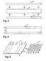
- the Fig. 1 to 7 illustrate the production of a sandwich component according to an embodiment.
- Fig. 7 shows the finished sandwich component 10, comprising a first cover layer 12-1, a second cover layer 12-2 and a core 14 arranged therebetween.
- the cover layers 12-1 and 12-2 are each made of an outer layer 16-1 of a fiber-reinforced thermoplastic material having "higher resistance” to a predetermined solvent (eg, DCM) and fused thereto (eg, thermally fused) to an inner layer 18-1 is formed from a "lower resistance” thermoplastic material over the predetermined solvent.
- a predetermined solvent eg, DCM
- the outer layer 16-1 is a fiber composite material in which a single or multilayer carbon fiber material is embedded in a matrix of PEEK.
- a thermoplastic material of cover layer 12-1 substantially resistant to an application of DCM, e.g. In an application of DCM this thermoplastic material is hardly attacked and in particular not significantly softened (dissolved).
- Such a thermoplastic material is referred to below as “solvent-resistant" or "DCM-resistant”.
- the inner layer 18-1 is formed in the example shown by PEI, which in this example z. B. a softenable by application of DCM (dissolvable) thermoplastic material of the cover layer 12-1.
- DCM dissolvable thermoplastic material
- Such a thermoplastic material is referred to below as “non-solvent resistant” or “not DCM resistant”.
- the core 14 has outer layers 20-1 and 20-2 facing the cover layers 12-1, 12-2, each of which is formed from a non-DCM-resistant thermoplastic material, here PEI, and a honeycomb-like inner structure 22, which is partially made of DCM material. Resistant thermoplastic material, here PEEK, and partially non-DCM-resistant thermoplastic material, here PEI is formed.
- PEI non-DCM-resistant thermoplastic material
- PEEK partially non-DCM-resistant thermoplastic material
- the inner layers 18-1, 18-2 of the cover layers 12-1, 12-2 are fused to one of the outer layers 20-1, 20-2 of the core 14, wherein the fusion by joining the by applying DCM to the respective merger (join) surfaces was performed.
- the sandwich component 10 can be particularly advantageous for. B. as a component, in particular flat extended component (fuselage section, panel, etc.) can be used in vehicle or aircraft.
- Fig. 1 to 6 show individual steps or stages in the production of the in Fig. 7 illustrated sandwich component 10th
- the cover layers 12-1, 12-2 and the core 14 are prefabricated.
- the prefabrication of the cover layers 12-1 and 12-2 takes place as in Fig. 1 exemplified for the cover layer 12-1 by fusing together (cohesive connection, preferably by thermal fusion) of the outer layer 16-1 previously prepared in fiber composite technology with the previously z. B. produced by extrusion inner layer 18-1.
- the resulting product, the cover layer 12-1 is in Fig. 2 shown.
- the prefabrication of the second cover layer 12-2 takes place in the same way.
- these layers 16,1, 18-1 z. B. also be melted together using a solvent, by the application of both materials, PEEK and PEI, suitable for such a fusion softens (dissolved) can be.
- the prefabrication of the core 14 is in the Fig. 3 to 5 illustrated.
- the foil 30 on the one hand and the foils 32-1, 32-2 on the other hand are preferably cohesively bonded to one another, ie fused (preferably again thermally).
- the resulting product is a composite film 34, which in Fig. 4 is shown.
- the core 14 is thus formed as a so-called folded honeycomb or folded honeycomb structure.
- the forming process used for this purpose is concerned, it is advantageously possible to resort to relevant prior art.
- a forming process was selected, by means of which, in particular, upper and lower "honeycomb cover layers" were formed from the correspondingly shaped (including folded) starting material 34.
- honeycomb cover layers are formed from the composite film 34 and in this composite film 34 both surfaces of the films 32-1, 32-2 made of PEI, that is formed from a non-DCM-resistant thermoplastic material, it is ensured that the core 14 resulting from the forming process has outer layers 20-1, 20-2 of non-DCM-resistant thermoplastic material.
- Fig. 6 The latter is important for the final step of the manufacture of the sandwich component, which is in Fig. 6 is illustrated.
- the prefabricated core 14 as shown between the two cover layers 12-1, 12-2 is arranged.
- the film 30 made of PEEK on both sides of the entire surface with the films 32-1 and 32-2 made of PEI coated.
- the inner structure of the core 14 is partially made of PEEK (film 30) and partially made of PEI (films 32-1, 32-2).
- z. B. the embodiment described above are advantageously modified so that in the 4 and 5 illustrated PEI coating of the PEEK film 30 on both sides in each case not the entire surface but as in Fig. 5 shown in dashed lines only in strip-shaped areas 36, which alternate in the processing direction of the composite film 34 with non-coated areas 38, wherein viewed in the processing direction width of the strips 36 and 38 is selected such that due to the forming process, the inner structure 22 of the core 14 only is formed from the non-coated areas 38, ie PEEK, whereas the PEI-coated areas 36, in conjunction with the PEEK film 30, form the cover layers 20-1 and 20-2 of the core 14.
Landscapes
- Engineering & Computer Science (AREA)
- Mechanical Engineering (AREA)
- Physics & Mathematics (AREA)
- Geometry (AREA)
- Manufacturing & Machinery (AREA)
- Laminated Bodies (AREA)
Abstract
Description
- Die vorliegende Erfindung betrifft ein Sandwichbauteil, also ein Bauteil, bei dem Werkstoffe mit verschiedenen Eigenschaften in Schichten zusammengesetzt sind, wobei diese Werkstoffschichten zumindest zwei Deckschichten und einen dazwischen angeordneten Kern umfassen. Ferner betrifft die Erfindung ein Verfahren zur Herstellung eines Sandwichbauteils.
- Bekannte Sandwichbauteile besitzen zumeist einen relativ dicken, jedoch leichtgewichtigen Kern, der zwischen zwei demgegenüber dünneren, jedoch mechanisch stabileren Deckschichten angeordnet und mit diesen Deckschichten verbunden (z. B. verklebt) ist.
- Derartige, in Sandwichbauweise gefertigte Bauteile können besonders vorteilhaft im Leichtbau eingesetzt werden, beispielsweise als Komponenten im Flugzeugbau.
- Bei bekannten Sandwichbauteilen besteht der Kern oftmals aus einem Schaumstoff, oder z. B. aus einer so genannten Wabenstruktur (z. B. aus Papier, Pappe, Kunststoff oder Metall). Als Deckschichten werden im Stand der Technik unter anderem z. B. Metallblech, Holz bzw. Sperrholz oder Faserverbundwerkstoffe eingesetzt.
- Ein grundsätzliches Problem bei der Herstellung eines Sandwichbauteils besteht darin, im Hinblick auf die Stabilität des fertigen Bauteils eine möglichst gute (mechanisch belastbare) Anbindung der Deckschichten an den Kern zu erzielen. Eine Möglichkeit hierfür ist eine "adhäsive Anbindung", d. h. das Verbinden des Kerns mit den Deckschichten mit Hilfe eines Klebstoffes oder einer Klebeschmelzschicht.
- Je nach Beschaffenheit der miteinander zu verklebenden Materialien ergibt sich bei diesem Verfahren jedoch oftmals der Nachteil einer unzureichenden Festigkeit der auf Adhäsion beruhenden Verbindung.
- Zur Vermeidung dieses Nachteils kommt in Betracht, die Deckschichten durch eine "kohäsive Anbindung" mit dem Kern zu verbinden, d. h. durch eine Schmelzverbindung zwischen Kern- und Deckschichten, ohne Verwendung eines Zusatzmaterials. Hierfür werden die aneinander angrenzenden Materialien erweicht bzw. aufgeschmolzen, unter Druck verbunden, und wieder verfestigt.
- Abgesehen davon, dass diese kohäsive Anbindung die Auswahl erweich- bzw. aufschmelzbarer und darüber hinaus entsprechend kompatibler (miteinander verschmelzbarer) Werkstoffe voraussetzt, ergibt sich bei diesem Verfahren in der Praxis oftmals der gravierende Nachteil (bzw. ein Grund, dieses Verfahren nicht anzuwenden), der darin besteht, dass durch das Erweichen bzw. Aufschmelzen der Materialien und das Zusammenfügen unter Druck die Deckschichten und/oder der Kern beschädigt werden.
- Dieses Problem ist z. B. besonders gravierend, wenn als Kern eine aus einem Thermoplastmaterial gebildete Wabenstruktur eingesetzt werden soll. Eine zur Schaffung einer kohäsiven Anbindung eingesetzte Temperatur- und Druckbeaufschlagung eines solchen Wabenkerns führt in der Regel zu einer unerwünschten und nachteiligen Verformung bzw. zu einem "Kollabieren" der Wabenstruktur.
- Es ist eine Aufgabe der vorliegenden Erfindung, ein Sandwichbauteil sowie ein Verfahren zur Herstellung eines Sandwichbauteils anzugeben, bei welchen die vorstehenden Probleme vermieden sind.
- Diese Aufgabe wird erfindungsgemäß durch ein Sandwichbauteil nach Anspruch 1 bzw. ein Herstellungsverfahren nach Anspruch 6 gelöst. Die abhängigen Ansprüche betreffen vorteilhafte Weiterbildungen der Erfindung.
- Das erfindungsgemäße Sandwichbauteil umfasst eine erste Deckschicht, eine zweite Deckschicht und einen dazwischen angeordneten Kern, wobei die Deckschichten jeweils aus einer Außenlage aus einem faserverstärkten Thermoplastmaterial mit höherer Resistenz gegenüber einem bestimmten Lösungsmittel und damit verschmolzen einer Innenlage aus einem Thermoplastmaterial mit niedrigerer Resistenz gegenüber dem Lösungsmittel gebildet sind, wobei der Kern Außenlagen aufweist, die jeweils aus einem Thermoplastmaterial mit niedrigerer Resistenz gegenüber dem Lösungsmittel gebildet sind, und eine Innenstruktur, die ganz oder teilweise aus einem Thermoplastmaterial mit höherer Resistenz gegenüber dem Lösungsmittel gebildet ist, und wobei die Innenlagen der Deckschichten mit jeweils einer der Außenlagen des Kerns unter Einsatz des Lösungsmittels verschmolzen wurden.
- Bei dem erfindungsgemäßen Verfahren zur Herstellung eines derartigen Sandwichbauteils werden zunächst die erste Deckschicht, die zweite Deckschicht und der Kern bereitgestellt (vorgefertigt).
- Sodann werden die Deckschichten an den im fertigen Sandwichbauteil dem Kern zugewandten Seiten der Innenlagen der Deckschichten durch Applikation eines vorbestimmten Lösungsmittels angelöst, und auch der Kern an den im fertigen Sandwichbauteil den Deckschichten zugewandten Seiten der Außenlagen des Kerns durch Applikation des vorbestimmten Lösungsmittels angelöst.
- Wesentlich ist hierbei die Verwendung eines Lösungsmittels, welches die genannten "Thermoplastmaterialien mit höherer Resistenz" kaum bis gar nicht angreift, insbesondere nicht nenneswert erweicht, wohingegen dieses Lösungsmittel die genannten "Thermoplastmaterialien mit niedrigerer Resistenz" angreift und insbesondere für die nachfolgende Verschmelzung hinreichend erweicht.
- Schließlich wird jede der mittels des verwendeten Lösungsmittels angelösten Innenlagen der Deckschichten an jeweils einer der angelösten Außenlagen des Kerns angefügt und somit verschmolzen.
- Der Begriff "verschmolzen" bedeutet ganz allgemein, dass die betreffenden Thermoplastmaterialien entweder zumindest oberflächlich auf mindestens die Erweichungstemperatur (im Falle verschiedener Thermoplastmaterialien die größere der beiden Erweichungstemperaturen) gebracht und in diesem Zustand aneinandergefügt wurden, oder dass die betreffenden Thermoplastmaterialien zumindest oberflächlich durch Applikation eines Lösungsmittels erweicht (angelöst) und aneinandergefügt wurden, wobei bei diesem Verschmelzungsvorgang in jedem Fall eine mehr oder weniger große Diffusion der Materialien der Fügepartner ineinander und somit eine "kohäsive Anbindung" erfolgt. Der Begriff "Erweichungstemperatur" bezeichnet hier eine Temperatur, bei welcher das betreffende Material erweicht bzw. aufschmilzt, so dass durch Anfügen eines ebenfalls erweichten bzw. aufgeschmolzenen weiteren Materials eine kohäsive Anbindung geschaffen werden kann. Der Begriff "durch Applikation eines Lösungsmittels erweicht (angelöst)" bezeichnet einen Angriff, bei welchem das betreffende Material soweit erweicht, dass durch Anfügen eines ebenfalls erweichten bzw. aufgeschmolzenen weiteren Materials eine kohäsive Anbindung geschaffen werden kann.
- Die Begriffe "höhere Resistenz" und "niedrigere Resistenz" (gegenüber dem vorbestimmten Lösungsmittel) sind im Rahmen der Erfindung so zu verstehen, dass ein Thermoplastmaterial mit höherer Resistenz bei Applikation des Lösungsmittels nur kaum bis gar nicht angegriffen wird (insbesondere nicht nenneswert erweicht), wohingegen das Thermoplastmaterial mit niedrigerer Resistenz bei Applikation des gleichen Lösungsmittels (und unter gleichen Applikationsbedingungen wie Temperatur und Einwirkzeit) stark angegriffen und hierbei jedenfalls erweicht (angelöst) wird.
- Der Begriff "erweicht (angelöst)" bezeichnet hier einen Zustand, in welchem das betreffende Material durch Anfügen eines ebenfalls erweichten bzw. aufgeschmolzenen weiteren Materials verschmolzen werden kann.
- Im Rahmen der Erfindung ist es keineswegs ausgeschlossen, dass mehrere verschiedene "Thermoplastmaterialien mit höherer Lösungsmittelresistenz", nachfolgend auch als "lösungsmittelresistente Thermoplastmaterialien" bezeichnet, und/oder mehrere verschiedene "Thermoplastmaterialien mit niedrigerer Lösungsmittelresistenz", nachfolgend auch als "nicht lösungsmittelresistente Thermoplastmaterialien" bezeichnet, im Sandwichbauteil vorhanden bzw. im Herstellungsverfahren verarbeitet werden.
- Anders ausgedrückt bezeichnen die Begriffe "höhere Resistenz" und "niedrigere Resistenz" den Umstand, dass wenigstens ein bestimmtes Lösungsmittel mitsamt Applikationsbedingungen (z. B. Applikationstemperatur und -dauer) angegeben werden kann, derart, dass das bzw. die lösungsmittelresistenten Thermoplastmaterialien bei dessen Applikation nicht für eine Verschmelzung geeignet erweicht (angelöst) werden, wohingegen das bzw. die nicht lösungsmittelresistenten Thermoplastmaterialien durch die gleiche Applikation für eine Verschmelzung geeignet erweicht (angelöst) werden.
- Für die konkrete Wahl des für die Erfindung vorzubestimmenden bzw. beim Herstellungsverfahren einzusetzenden Lösungsmittels, und damit im Zusammenhang stehend die konkrete Wahl von gegenüber diesem Lösungsmittel "resistenten" und "nicht resistenten" Thermoplastmaterialien stehen dem Fachmann vielfältige Möglichkeiten zur Verfügung. Vorteilhaft kann diesbezüglich insbesondere auf bereits publizierte Tabellen und Nachschlagewerke betreffend die jeweilige Resistenz einer Vielzahl von Thermoplastmaterialien gegenüber bestimmmten Lösungsmitteln zurückgegriffen werden.
- Im Rahmen der Erfindung nutzbare Methoden zur Bestimmung bzw. Charakterisierung und Vorhersage von Resistenzen von Materialien gegenüber Lösungsmitteln sind z. B. beschrieben in "Hansen Charles M., Hansen Solubility Parameters - A User's Handbook", Second Edition, CRC Press, Taylor & Francis Group, 2007, ISBN: 0-8493-7248-8".
- Wie oben bereits erläutert besteht eine Besonderheit des erfindungsgemäßen Sandwichbauteils darin, dass die Deckschichten jeweils aus einer Außenlage aus einem faserverstärkten "lösungsmittelresistenten" Thermoplastmaterial und damit verschmolzen einer Innenlage aus einem davon verschiedenen, "nicht lösungsmittelresistenten" Thermoplastmaterial gebildet sind. Insofern besitzt jede der Deckschichten zwei Lagen, die jedoch (thermisch oder alternativ durch geeignete Lösungsmittelapplikation) miteinander verschmolzen und somit vorteilhaft kohäsiv miteinander verbunden sind, wobei darüber hinaus eine kohäsive Anbindung vorteilhaft auch zwischen den Deckschichten und dem Kern dadurch vorgesehen ist, dass durch geeignete Lösungsmittelapplikation die jeweils aus einem "nicht lösungsmittelresistenten" Thermoplastmaterial gebildeten Außenlagen des Kerns mit den ebenfalls jeweils aus einem "nicht lösungsmittelresistenten" Thermoplastmaterial gebildeten Innenlagen der Deckschichten verschmolzen sind.
- Das erfindungsgemäße Sandwichbauteil besitzt somit sämtliche Vorteile der eingangs erläuterten "kohäsiven Anbindung" der Deckschichten an den Kern, vermeidet hierbei jedoch die Gefahr einer nennenswerten Beschädigung der Deckschichten und/oder des Kerns im Rahmen der Herstellung des Sandwichbauteils, weil es für die Aneinanderfügung der Deckschichten und des Kerns zur Schaffung der kohäsiven Anbindung möglich ist, an den Deckschichten und am Kern ein Lösungsmittel zu applizieren, welches bei den Deckschichten selektiv im Wesentlichen nur die Deckschicht-Innenlagen angreift und erweicht (anlöst) und beim Kern selektiv im Wesentlichen nur die Kern-Außenlagen angreift und erweicht (anlöst).
- Mit anderen Worten ist ein Zusammenfügen und somit Verschmelzen der Deckschichten und des Kerns vorteilhaft derart möglich, dass hierbei weder die Außenlagen der Deckschichten noch die Innenstruktur des Kerns erweicht.
- In einer Ausführungsform ist vorgesehen, dass die nicht lösungsmittelresistenten Thermoplastmaterialien einerseits einer Innenlage einer Deckschicht und andererseits der damit verschmolzenen Außenlage des Kerns identisch sind.
- In einer Weiterbildung dieser Ausführungsform sind sämtliche nicht lösungsmittelresistenten Thermoplastmaterialien, also diejenigen der Innenlagen der beiden Deckschichten und diejenigen der Außenlagen des Kerns, identisch. Falls, was jedoch weniger bevorzugt ist, die nicht lösungsmittelresistenten Thermoplastmaterialien einer Innenlage einer Deckschicht und der damit verschmolzenen Außenlage des Kerns nicht identisch gewählt sind, so ist lediglich deren Kompatibilität im Sinne einer Verschmelzbarkeit (Mischbarkeit) der beiden Materialien sicherzustellen.
- In einer Ausführungsform ist wenigstens eines der Thermoplastmaterialien gewählt aus der Gruppe bestehend aus ABS (Acrynitril-Butadien-Styrol), PA (Polyamid), PBT (Polybutylenterephthalat), PC (Polycarbonat), PEEK (Polyetheretherketon), PEI (Polyetherimid), PES (Polyethersulfon), PET (Polyethyleneterephthalat), PP (Polypropylen), PPS (Polyphenylensulfid), PPSU (Polyphenylsulfon), PSU (Polysulfon).
- In einer insbesondere für Anwendungen des Sandwichbauteils in der Luft- und Raumfahrtindustrie geeigneten Ausführungsform ist wenigstens eines der Thermoplastmaterialien z. B. gewählt aus der Gruppe bestehend aus PEEK, PEI, PES, PPS, PPSU, PSU.
- Insbesondere im Hinblick auch auf andere Anwendungen kann z. B. vorgesehen sein, dass wenigstens eines der Thermoplastmaterialien gewählt ist aus der Gruppe bestehend aus ABS, PA, PBT, PC, PP.
- In einer Ausführungsform ist als lösungsmittelresistentes Thermoplastmaterial PEEK (z. B. resistent gegenüber Dichlormethan (DCM)) vorgesehen, sei es für wenigstens eine (oder beide) Außenlagen der Deckschichten und/oder die Innenstruktur des Kerns.
- In einer Ausführungsform ist als nicht lösungsmittelresistentes Thermoplastmaterial PEI (z. B. nicht resistent gegenüber DCM) vorgesehen, sei es für wenigstens eine (oder beide) Innenlagen der Deckschichten und/oder wenigstens eine (oder beide) Außenlagen des Kerns.
- In einer Ausführungsform ist die Außenlage wenigstens einer der Deckschichten mit Kohlenstofffasern verstärkt. Anstelle von Kohlenstofffasern können jedoch auch andere Verstärkungsfasern vorgesehen sein, z. B. Glasfasern. Zumeist ist es zweckmäßig, die Außenlagen der Deckschichten mit gleichartigen Fasern zu verstärken, also beide Außenlagen z. B. mit Kohlenstofffasern oder mit Glasfasern. Es soll jedoch nicht ausgeschlossen sein, die Außenlagen der beiden Deckschichten mit verschiedenartigem Fasermaterial zu verstärken.
- Das Fasermaterial, welches in den Außenlagen der Deckschichten von dem lösungsmittelresistenten Thermoplastmaterial als "Matrixmaterial" umgeben ist, kann jeweils z. B. in Form von einer oder mehrerer Lagen eines Gewebes, Geleges oder Geflechtes vorgesehen sein. Alternativ oder zusätzlich kommt in Betracht, wirr im Matrixmaterial angeordnete "kurze Fasern" vorzusehen.
- Das Matrixmaterial kann für beide Deckschichten gleichartig gewählt sein. Es soll jedoch nicht ausgeschlossen sein, für die Außenlagen der beiden Deckschichten verschiedenartige lösungsmittelresistente Thermoplastmaterialien vorzusehen.
- In einer Ausführungsform ist als Matrixmaterial für die Außenlage wenigstens einer, insbesondere beider Deckschichten PEEK verwendet.
- In einer Ausführungsform ist als Material für die Innenlage wenigstens einer, insbesondere beider Deckschichten PEI verwendet.
- In einer Ausführungsform ist für wenigstens eine, insbesondere beide Deckschichten vorgesehen, dass die Dicke der Deckschicht mindestens 0,2 mm, insbesondere mindestens 0,4 mm beträgt.
- In einer Ausführungsform ist für wenigstens eine, insbesondere beide Deckschichten vorgesehen, dass die Dicke der Deckschicht höchstens 6 mm, insbesondere höchstens 3 mm beträgt.
- In einer Ausführungsform ist für wenigstens eine, insbesondere beide Deckschichten vorgesehen, dass die Dicke der Innenlage mindestens das 0,01-fache, insbesondere mindestens das 0,1-fache der Gesamtdicke der betreffenden Deckschicht beträgt.
- In einer Ausführungsform ist für wenigstens eine, insbesondere beide Deckschichten vorgesehen, dass die Dicke der Innenlage höchstens das 0,5-fache, insbesondere höchstens das 0,3-fache der Gesamtdicke der betreffenden Deckschicht beträgt.
- In einer Ausführungsform ist der Kern von einer Schaumstoffschicht (Innenstruktur) aus einem lösungsmittelresistenten Thermoplastmaterial mit beiderseits damit verschmolzenen Außenlagen jeweils aus einem nicht lösungsmittelresistenten Thermoplastmaterial gebildet.
- In einer anderen Ausführungsform ist der Kern ein so genannter Wabenkern. Sandwichbauteile mit Wabenkern sind aus dem Stand der Technik bekannt, etwa mit einem Wabenkern aus Pappe, harzgetränktem Papier, Faserkunststoff oder dünnen Aluminiumfolien.
- Wenn bei dem erfindungsgemäßen Sandwichbauteil der Kern als Wabenkern ausgebildet ist, so muss dieser Außenlagen aufweisen, die aus einem nicht lösungsmittelresistentenThermoplastmaterial gebildet sind, und eine wabenförmige Innenstruktur, die wenigstens teilweise aus einem lösungsmittelresistenten Thermoplastmaterial besteht.
- Hierfür denkbar wäre beispielsweise eine aus dem lösungsmittelresistenten Thermoplastmaterial (z. B. PEEK im Falle von z. B. DCM als Lösungsmittel) gebildete Wabenstruktur, die beiderseits mit Außenlagen (äußerste Lagen von "Wabenstrukturdeckschichten") aus jeweils einem nicht lösungsmittelresistenten Thermoplastmaterial (z. B. PEI im Falle von z. B. DCM als Lösungsmittel) fest verbunden, insbesondere (z. B. thermisch) verschmolzen ist.
- In einer Ausführungsform sind die beiden Außenlagen des Kerns aus einem identischen nicht lösungsmittelresistenten Thermoplastmaterial gebildet.
- Gemäß einer bevorzugten Weiterbildung der Ausführung mit einem Wabenkern ist vorgesehen, dass derselbe als eine so genannte Faltwabe bzw. Faltwabenstruktur ausgebildet ist.
- Eine Faltwabenstruktur ist dadurch gekennzeichnet, dass diese ausgehend von einem flächigen Körper aus einem plastisch verformbaren Material (z. B. thermoplastische Kunststofffolie) gebildet wurde, indem dieser Körper derart plastisch verformt (einschließlich "gefaltet") wurde, dass damit die Wabenstruktur entsteht. Gegebenenfalls kann dem Verformungs- und Faltprozess auch ein Einbringen von Schnitten in das flächige Material vorangehen.
- Für die konkrete Gestaltung einer solchen Faltwabenstruktur bzw. deren Herstellung kann im Rahmen der Erfindung vorteilhaft z. B. auf diesbezüglichen Stand der Technik zurückgegriffen werden. Lediglich beispielhaft seinen hierzu die Patentveröffentlichungen
WO 97/03816 WO 00/32382 DE 10 2006 056 353 B3 undDE 10 2008 028 864 B4 genannt. - Der hier verwendete Begriff "Faltwabenstruktur" soll sowohl Strukturen mit vertikal (in "Sandwichrichtung") verlaufenden Zellen- bzw. Wabenwänden als auch Strukturen mit schräg verlaufenden Wänden umfassen. Demgegenüber werden im Stand der Technik (vgl. z. B.
DE 10 2006 056 353 B3 undDE 10 2008 028 864 B4 ) erstere Strukturen, jedenfalls bei im Querschnittt sechseckigen Waben, oftmals auch als "honeycomb"-Strukturen und zweitere Strukturen als Faltwaben bezeichnet. - In einer Ausführungsform ist vorgesehen, dass die Dicke des Kerns mindestens 3 mm, insbesondere mindestens 6 mm oder mindestens 10 mm beträgt.
- In einer Ausführungsform ist vorgesehen, dass die Dicke des Kerns höchstens 50 mm, insbesondere höchstens 25 mm beträgt. Im Hinblick auf den Anwendungsfall einer Nutzung des Sandwichbauteils (auch) zur Wärmedämmung ist jedoch auch denkbar, den Kern (insbesondere z. B. mit einer Innenstruktur aus Schaumstoff) mit einer Dicke von mehr als 25 mm vorzusehen, z. B. bis zu einer Dicke von 100 mm oder sogar 200 mm.
- In einer Ausführungsform ist für wenigstens eine, insbesondere beide Außenlagen des Kerns vorgesehen, dass die Dicke der aus lösungsmittelresistentem Thermoplastmaterial gebildeten Außenlage mindestens das 0,0001-fache, insbesondere mindestens das 0,01-fache der Gesamtdicke des Kerns beträgt.
- In einer Ausführungsform ist für wenigstens eine, insbesondere beide Außenlagen des Kerns vorgesehen, dass die Dicke der aus lösungsmittelresistentem Thermoplastmaterial gebildeten Außenlage höchstens das 0,1-fache, insbesondere höchstens das 0,05-fache der Gesamtdicke des Kerns beträgt.
- Die Besonderheit des erfindungsgemäßen Verfahrens zur Herstellung eines Sandwichbauteils der hier beschriebenen Art besteht darin, die wie beschrieben speziell ausgebildeten (vorgefertigten) Deckschichten mit dem wie beschrieben speziell ausgebildeten (vorgefertigten) Kern unter Einsatz eines geeigneten Lösungsmittels zu verschmelzen.
- Zum Bereitstellen der Deckschichten kann vorteilhaft jeweils z. B. eine vorgefertigte Außenlage (flächiger Faserverbundwerkstoff) mit einer vorgefertigten Innenlage (z. B. konfektioniertes Thermoplastfolienmaterial) durch Anwendung von Druck und Temperatur, z. B. in einem Formwerkzeug oder z. B. in einem kontinuierlichen Laminierprozess, verschmolzen werden. Alternativ kommt in Betracht, bereits bei der Herstellung des Faserverbundwerkstoffes (Außenlage) die Innenlage sogleich "aufzulaminieren".
- Zum Bereitstellen des Kerns kann z. B. in einem ähnlichen Verschmelzungsprozess eine vorgefertigte Schaumstofflage aus einem lösungsmittelresistenten Thermoplastmaterial beiderseits mit Außenlagen eines nicht lösungsmittelresistenten Thermoplastmaterials versehen werden.
- In einer bevorzugten Ausführungsform wird jedoch zum Bereitstellen des Kerns eine mit einem nicht lösungsmittelresistenten Thermoplastmaterial beidseitig beschichtete Folie eines lösungsmittelresistenten Thermoplastmaterials zur Ausbildung einer Faltwabenstruktur umgeformt.
- Ein derartiges Verfahren zur Herstellung einer Faltwabenstruktur kann, abgesehen von der im Rahmen der Erfindung hierfür mit einem nicht lösungsmittelresistenten Thermoplastmaterial beschichteten Folie eines lösungsmittelresistenten Thermoplastmaterials, vorteilhaft gemäß an sich bekannter Verfahren bewerkstelligt werden. Ein Beispiel hierfür ist das in der
WO 00/32382 - Bereitstellen eines flächigen Körpers aus einem plastisch verformbaren Material,
- Verformen des flächigen Körpers in streifenförmigen Bereichen vieleckig, sinusoder kreisförmig, wobei die zwischen diesen Bereichen liegenden streifenförmigen Bereich abwechselnd ganz oder gar nicht aus der Ebene des flächigen Ausgangskörpers geformt werden, und
- Falten der vieleckig, sinus- oder kreisförmig plastisch verformten Bereiche gegenüber den streifenförmigen Bereichen um etwa 90°.
- Die resultierende Faltwabenstruktur ist dann aus einer Mehrzahl von in Reihen angeordneten Zellen (Waben) gebildet, wobei die Zellen seitliche Zellwände aufweisen, die ringförmig aneinander anschließen und zu den Öffnungsseiten der Zelle hin von Wabendeckschichtebenen begrenzt werden, wobei die Zellen insbesondere in beiden Wabendeckschichtebenen vollständig überbrückt sein können. Die Zellwände können hierbei ganz oder teilweise dauerhaft miteinander verbunden sein.
- Wenn bei diesem an sich bekannten Verfahren zur Herstellung einer Faltwabenstruktur im Rahmen der Erfindung als flächiger Ausgangskörper wie erwähnt eine aus verschiedenen Thermoplastmaterialien in Schichten zusammengesetzte Folie verwendet wird, z. B. mit einer Innenlage aus lösungsmittelresistentem Thermoplastmaterial und beiderseits damit verschmolzen Außenlagen aus einem jeweils nicht lösungsmittelresistenten Thermoplastmaterial, so ergibt sich ein bei der Erfindung einsetzbarer Faltwabenkern mit Außenlagen (äußerste Lage der Wabenstrukturdeckschichten) aus dem betreffenden nicht lösungsmittelresistenten Thermoplastmaterial und einer Innenstruktur, die teilweise aus lösungsmittelresistentem und teilweise aus nicht lösungsmittelresistentem (jedoch vorteilhaft "innenliegendem" und somit nicht so leicht angreifbarem) Thermoplastmaterial gebildet ist. Im letzten Schritt des erfindungsgemäßen Verfahrens zur Herstellung eines Sandwichbauteils werden die Innenlagen der Deckschichten mit jeweils einer der Außenlagen des Kerns unter Einsatz des Lösungsmittels verschmolzen.
- Bei diesem Verschmelzen unter Einsatz einer Applikation des Lösungsmittels, ggf. auch unter Anwendung einer erhöhten, z. B. über Raumtemperatur erhöhtenTemperatur, wird zunächst das Lösungsmittel zumindest solange auf die betreffenden Fügeflächen einwirken gelassen, bis diese für die Verschmelzung geeignet erweicht (angelöst) sind.
- Die Einwirkungsdauer des Lösungsmittels und/oder eine hierbei angewendete Temperatur können auch höher als unbedingt erforderlich gewählt werden, wobei in diesem Fall lediglich sichergestellt sein sollte, dass durch diese "Applikationsbedingung" kein wesentlicher Angriff (Erweichung) der nicht am Fügeprozess beteiligten Thermoplastmaterialanteile erfolgt.
- Gemäß einer vorteilhaften Weiterbildung der Bereitstellung des Kerns als eine Faltwabenstruktur durch Umformen einer mit nicht lösungsmittelresistentem Thermoplastmaterial beschichteten Folie eines lösungsmittelresistenten Thermoplastmaterials ist vorgesehen, dass diese Beschichtung in Anpassung an den konkreten Umformprozess nur bereichsweise derart durchgeführt wird, dass das nicht lösungsmittelresistente Thermoplastmaterial an der fertigen Faltwabenstruktur nur im Bereich der Faltwabenstrukturdeckschichten vorhanden ist, nicht jedoch im Bereich der Innenstruktur der Faltwabenstruktur. Mit dieser Weiterbildung wird die Gefahr beseitigt, dass bei dem finalen Herstellungsschritt für das Sandwichbauteil unter Einsatz des Lösungsmittels eine Erweichung der ansonsten in der Innenstruktur vorhandenen durch das Lösungsmittel erweichbaren Thermoplastanteile erfolgt.
- Die Erfindung wird nachfolgend anhand eines Ausführungsbeispiels mit Bezug auf die beigefügten Zeichnungen weiter beschrieben. Es stellen jeweils schematisch dar:
- Fig. 1
- ein Vorfertigen einer Deckschicht für ein Sandwichbauteil,
- Fig. 2
- die vorgefertigte Deckschicht,
- Fig. 3
- eine Vorfertigung einer Thermoplastfolie zur Verwendung als Ausgangsmaterial zur Herstellung einer Faltwabenstruktur,
- Fig. 4
- die vorgefertigte Thermoplastfolie,
- Fig. 5
- eine Vorfertigung der Faltwabenstruktur aus der Thermoplastfolie von
Fig. 4 , - Fig. 6
- eine Fertigung des Sandwichbauteils durch Verschmelzen zweier Deckschichten der in
Fig. 2 dargestellten Art mit einem gemäß des Verfahrens vonFig. 5 vorgefertigten Kerns, und - Fig. 7
- das fertige Sandwichbauteil.
- Die
Fig. 1 bis 7 veranschaulichen die Herstellung eines Sandwichbauteils gemäß eines Ausführungsbeispiels. - Zunächst wird mit Bezug auf
Fig. 7 auf die Gestaltung des fertigen Sandwichbauteils 10 eingegangen. Sodann wird anhand derFig. 1 bis 6 das zur Herstellung des Sandwichbauteils 10 verwendete Verfahren beschrieben. -
Fig. 7 zeigt das fertige Sandwichbauteil 10, umfassend eine erste Deckschicht 12-1, eine zweite Deckschicht 12-2 und einen dazwischen angeordneten Kern 14. - Die Deckschichten 12-1 und 12-2 sind jeweils aus einer Außenlage 16-1 aus einem faserverstärkten Thermoplastmaterial mit "höherer Resistenz" gegenüber einem vorbestimmten Lösungsmittel (z. B. DCM) und damit verschmolzen (z. B. thermisch verschmolzen) einer Innenlage 18-1 aus einem Thermoplastmaterial mit "niedrigerer Resistenz" gegenüber dem vorbestimmten Lösungsmittel gebildet.
- Im dargestellten Beispiel handelt es sich bei der Außenlage 16-1 um einen Faserverbundwerkstoff, bei welchem ein ein- oder mehrlagiges Kohlenstofffasermaterial in einer Matrix von PEEK eingebettet ist. Das PEEK stellt in diesem Beispiel z. B. ein gegenüber einer Applikation von DCM im Wesentlichen resistentes Thermoplastmaterial der Deckschicht 12-1 dar, d.h. bei einer Applikation von DCM wird dieses Thermoplastmaterial kaum angegriffen und insbesondere nicht nennenswert erweicht (angelöst). Ein solches Thermoplastmaterial wird nachfolgend vereinfachend als "lösungsmittelresistent" bzw. "DCM-resistent" bezeichnet.
- Demgegenüber ist die Innenlage 18-1 im dargestellten Beispiel von PEI gebildet, welches in diesem Beispiel z. B. ein durch Applikation von DCM erweichbares (anlösbares) Thermoplastmaterial der Deckschicht 12-1 darstellt. Ein solches Thermoplastmaterial wird nachfolgend vereinfachend als "nicht lösungsmittelresistent" bzw. "nicht DCM-resistent" bezeichnet.
- Der Kern 14 weist den Deckschichten 12-1, 12-2 zugewandte Außenlagen 20-1 und 20-2 auf, die jeweils aus einem nicht DCM-resistenten Thermoplastmaterial, hier PEI, gebildet sind und eine wabenartige Innenstruktur 22, die teilweise aus DCM-resistentem Thermoplastmaterial, hier PEEK, und teilweise aus nicht DCM-resistentem Thermoplastmaterial, hier PEI, gebildet ist.
- Die Innenlagen 18-1, 18-2 der Deckschichten 12-1, 12-2 sind mit jeweils einer der Außenlagen 20-1, 20-2 des Kerns 14 verschmolzen, wobei das Verschmelzen durch Aneinanderfügung der durch Applikation von DCM an den betreffenden Verschmelzungs(füge)flächen durchgeführt wurde.
- Das Sandwichbauteil 10 kann besonders vorteilhaft z. B. als Komponente, insbesondere flächig ausgedehnte Komponente (Rumpfabschnitt, Paneel etc.) im Fahrzeug- oder Flugzeugbau verwendet werden.
- Die
Fig. 1 bis 6 zeigen einzelne Schritte bzw. Stadien bei der Herstellung des inFig. 7 dargestellten Sandwichbauteils 10. - In einem ersten Schritt werden die Deckschichten 12-1, 12-2 sowie der Kern 14 vorgefertigt.
- Die Vorfertigung der Deckschichten 12-1 und 12-2 erfolgt wie in
Fig. 1 beispielhaft für die Deckschicht 12-1 veranschaulicht durch ein miteinander Verschmelzen (kohäsive Anbindung, bevorzugt durch thermische Verschmelzung) der zuvor in Faserverbundtechnologie hergestellten Außenlage 16-1 mit der zuvor z. B. durch Extrusion hergestellten Innenlage 18-1. Das resultierende Produkt, die Deckschicht 12-1 ist inFig. 2 dargestellt. Die Vorfertigung der zweiten Deckschicht 12-2 erfolgt in gleicher Weise. Alternativ zu einer rein thermischen Verschmelzung der Außenlage 16-1 und der Innenlage 18-1 könnten diese Lagen 16,1, 18-1 z. B. auch unter Einsatz eines Lösungsmittels miteinander verschmolzen werden, durch dessen Applikation beide Materialien, PEEK und PEI, für eine solche Verschmelzung geeignet erweicht (angelöst) werden können. - Abweichend von dem mit den
Fig. 1 und 2 veranschaulichten Verfahren kommt in Betracht, bei der Vorfertigung der Außenlage sogleich die Innenlage "aufzulaminieren", d. h. die Einbettung des Fasermaterials in der Außenlage und die Anbindung der Innenlage in einem Schritt, z. B. in einem Formwerkzeug zu bewerkstelligen. - Die Vorfertigung des Kerns 14 ist in den
Fig. 3 bis 5 veranschaulicht. - Zunächst wird, wie in
Fig. 3 gezeigt, eine vorgefertigte Folie 30 aus PEEK beiderseits mit Folien 32-1 und 32-2 aus PEI beschichtet. Bevorzugt werden die Folie 30 einerseits und die Folien 32-1, 32-2 andererseits kohäsiv miteinander verbunden, d. h. verschmolzen (bevorzugt wieder thermisch). - Das resultierende Produkt ist eine Verbundfolie 34, die in
Fig. 4 dargestellt ist. - Sodann wird, wie in
Fig. 5 symbolisiert, mit der Verbundfolie 34 als Ausgangsmaterial (Fig. 5 links) durch einen Umformprozess eine den Kern 14 darstellende Faltwabenstruktur geschaffen (Fig. 5 rechts). - Im dargestellten Beispiel wird der Kern 14 somit als eine so genannte Faltwabe bzw. Faltwabenstruktur ausgebildet. Was den hierfür verwendeten Umformprozess anbelangt, so kann vorteilhaft auf diesbezüglichen Stand der Technik zurückgegriffen werden.
- Im dargestellten Beispiel wurde ein Umformprozess gewählt, mittels welchem insbesondere auch obere und untere "Wabenstrukturdeckschichten" aus dem entsprechend umgeformten (einschließlich gefalteten) Ausgangsmaterial 34 ausgebildet wurden.
- Da diese Wabenstrukturdeckschichten (wie auch die Innenstruktur) aus der Verbundfolie 34 gebildet sind und bei dieser Verbundfolie 34 beide Oberflächen von den Folien 32-1, 32-2 aus PEI, also von einem nicht DCM-resistenten Thermoplastmaterial gebildet sind, ist sichergestellt, dass der aus dem Umformprozess resultierende Kern 14 Außenlagen 20-1, 20-2 aus nicht DCM-resistentem Thermoplastmaterial besitzt.
- Letzteres ist von Bedeutung für den letzten Schritt der Herstellung des Sandwichbauteils, der in
Fig. 6 veranschaulicht ist. In diesem Schritt wird der vorgefertigte Kern 14 wie dargestellt zwischen den beiden Deckschichten 12-1, 12-2 angeordnet. Dann werden die Innenlagen 18-1, 18-2 der Deckschichten 12-1, 12-2 mit jeweils einer der Außenlagen 20-1, 20-2, nach vorheriger Applikation von DCM zumindest an den miteinander zu verschmelzenden Fügeflächen, unter Anwendung von Druck, und ggf. auch einer erhöhten, z. B. über Raumtemperatur erhöhten Temperatur, verschmolzen. Es resultiert das inFig. 7 dargestellte fertige Sandwichbauteil 10. - Bei dem oben beschriebenen Ausführungsbeispiel wurde die Folie 30 aus PEEK beiderseits vollflächig mit den Folien 32-1 und 32-2 aus PEI beschichtet.
- Daraus resultiert, dass die Innenstruktur des Kerns 14 teilweise aus PEEK (Folie 30) und teilweise aus PEI (Folien 32-1, 32-2) besteht.
- Insofern muss beim finalen Herstellungsschritt für das Sandwichbauteil darauf geachtet werden, dass möglichst keine unerwünschte Schädigung, z. B. Erweichung der in der Innenstruktur 22 des Kerns 14 vorhandenen Thermoplastanteile erfolgt, die nicht resistent gegenüber dem betreffenden Lösungsmittel, hier DCM, sind. Dem kann in der Praxis z. B. dadurch Rechnung getragen werden, dass die Prozessbedingungen bei der Applikation des betreffenden Lösungsmittels, hier DCM, so eingestellt werden, dass dieses Lösungsmittel hierbei nicht nennenswert bzw. in schädigenden Mengen in den Bereich der Innenstruktur 22 des Kerns 14 vordringt.
- Unter diesem Aspekt ist gemäß einer vorteilhaften Weiterbildung der Bereitstellung der Faltwabenstruktur durch Umformen einer mit nicht lösungsmittelresistentem Thermoplastmaterial beschichteten Folie eines lösungsmittelresistenten Thermoplastmaterials vorgesehen, dass diese Beschichtung in Anpassung an den konkreten Umformprozess nur bereichsweise derart durchgeführt wird, dass das nicht lösungsmittelresistente Thermoplastmaterial an der fertigen Faltwabenstruktur nur im Bereich der Faltwabenstrukturdeckschichten vorhanden ist.
- Dementsprechend könnte z. B. das oben beschriebene Ausführungsbeispiel vorteilhaft so modifiziert werden, dass die in den
Fig. 4 und 5 veranschaulichte PEI-Beschichtung der PEEK-Folie 30 zu beiden Seiten jeweils nicht vollflächig sondern wie inFig. 5 gestrichelt eingezeichnet nur in streifenförmigen Bereichen 36 erfolgt, die sich in Verarbeitungsrichtung der Verbundfolie 34 mit nicht-beschichteten Bereichen 38 abwechseln, wobei die in Verarbeitungsrichtung betrachtete Breite der Streifen 36 und 38 derart gewählt ist, dass infolge des Umformprozesses die Innenstruktur 22 des Kerns 14 nur aus den nicht-beschichteten Bereichen 38, also PEEK, gebildet wird, wohingegen aus den PEI-beschichteten Bereichen 36, im Verbund mit der PEEK-Folie 30, die Deckschichten 20-1 und 20-2 des Kerns 14 gebildet werden.
Claims (10)
- Sandwichbauteil mit einer ersten Deckschicht (12-1), einer zweiten Deckschicht (12-2) und einem dazwischen angeordneten Kern (14),
wobei die Deckschichten (12-1, 12-2) jeweils aus einer Außenlage (16-1, 16-2) aus einem faserverstärkten Thermoplastmaterial mit höherer Resistenz gegenüber einem bestimmten Lösungsmittel und damit verschmolzen einer Innenlage (18-1, 18-2) aus einem Thermoplastmaterial mit niedrigerer Resistenz gegenüber dem Lösungsmittel gebildet sind,
wobei der Kern (14) Außenlagen (20-1, 20-2) aufweist, die jeweils aus einem Thermoplastmaterial mit niedrigerer Resistenz gegenüber dem Lösungsmittel gebildet sind, und eine Innenstruktur (22), die ganz oder teilweise aus einem Thermoplastmaterial mit höherer Resistenz gegenüber dem Lösungsmittel gebildet ist,
und wobei die Innenlagen (18-1, 18-2) der Deckschichten (12-1, 12-2) mit jeweils einer der Außenlagen (20-1, 20-2) des Kerns (14) unter Einsatz des Lösungsmittels verschmolzen wurden. - Sandwichbauteil nach Anspruch 1, wobei die Thermoplastmaterialien mit niedrigerer Lösungsmittelresistenz einerseits einer Innenlage (18-1, 18-2) einer Deckschicht (12-1, 12-2) und andererseits der damit verschmolzenen Außenlage (20-1, 20-2) des Kerns (14) identisch sind.
- Sandwichbauteil nach einem der vorangehenden Ansprüche, wobei wenigstens eines der Thermoplastmaterialien ausgewählt ist aus der Gruppe bestehend aus ABS, PA, PBT, PC, PEEK, PEI, PES, PET, PP, PPS, PPSU, PSU.
- Sandwichbauteil nach einem der vorangehenden Ansprüche, wobei der Kern (14) ein Wabenkern ist.
- Sandwichbauteil nach Anspruch 4, wobei der Wabenkern (14) eine Faltwabenstruktur ist.
- Verfahren zur Herstellung eines Sandwichbauteils (10) nach einem der vorangehenden Ansprüche, umfassend die Schritte:a) Bereitstellen der ersten Deckschicht (12-1), der zweiten Deckschicht (12-2) und des Kerns (14),b) Anlösen der Deckschichten (12-1, 12-2) an den im fertigen Sandwichbauteil (10) dem Kern (14) zugewandten Seiten der Innenlagen (18-1, 18-2) der Deckschichten (12-1, 12-2) durch Applikation des bestimmten Lösungsmittels, und Anlösen des Kerns (14) an den im fertigen Sandwichbauteil (10) den Deckschichten (12-1, 12-2) zugewandten Seiten der Außenlagen (20-1, 20-2) des Kerns (14) durch Applikation des Lösungsmittels, undc) Aneinanderfügen und somit Verschmelzen der angelösten Innenlagen (18-1, 18-2) der Deckschichten (12-1, 12-2) mit jeweils einer der angelösten Außenlagen (20-1, 20-2) des Kerns (14).
- Verfahren nach Anspruch 6, wobei im Schritt a) zum Bereitstellen der Deckschichten (12-1, 12-2) jeweils eine vorgefertigte Außenlage (16-1, 16-2) mit einer vorgefertigten Innenlage (18-1, 18-2) verschmolzen wird.
- Verfahren nach Anspruch 6 oder 7, wobei in Schritt a) zum Bereitstellen des Kerns (14) eine mit dem Thermoplastmaterial (32-1, 32-2) mit niedrigerer Lösungsmittelresistenz beschichtete Folie (30) eines Thermoplastmaterials mit höherer Lösungsmittelresistenz zur Ausbildung einer Faltwabenstruktur umgeformt wird.
- Verfahren nach Anspruch 8, wobei die Folie (30) des Thermoplastmaterials mit höherer Lösungsmittelresistenz mit dem Thermoplastmaterial (32-1, 32-2) mit niedrigerer Lösungsmittelresistenz nur bereichsweise derart beschichtet wird, dass infolge des nachfolgenden Umformprozesses die Innenstruktur (22) des Kerns (14) aus den nicht-beschichteten Bereichen (38) und die Außenlagen (20-1, 20-2) des Kerns (14) aus den beschichteten Bereichen (36) ausgebildet werden.
- Verfahren nach einem der Ansprüche 6 bis 9, wobei das Lösungsmittel ein organisches Lösungsmittel ist, insbesondere ein Chlorkohlenwasserstoff wie beispielsweise DCM (Dichlormethan).
Applications Claiming Priority (1)
| Application Number | Priority Date | Filing Date | Title |
|---|---|---|---|
| DE102014007511.7A DE102014007511A1 (de) | 2014-05-23 | 2014-05-23 | Sandwichbauteil sowie Verfahren zur Herstellung eines Sandwichbauteils |
Publications (2)
| Publication Number | Publication Date |
|---|---|
| EP2946924A1 true EP2946924A1 (de) | 2015-11-25 |
| EP2946924B1 EP2946924B1 (de) | 2021-01-06 |
Family
ID=53269288
Family Applications (1)
| Application Number | Title | Priority Date | Filing Date |
|---|---|---|---|
| EP15001549.3A Active EP2946924B1 (de) | 2014-05-23 | 2015-05-20 | Sandwichbauteil sowie verfahren zur herstellung eines sandwichbauteils |
Country Status (3)
| Country | Link |
|---|---|
| US (1) | US10414116B2 (de) |
| EP (1) | EP2946924B1 (de) |
| DE (1) | DE102014007511A1 (de) |
Citations (7)
| Publication number | Priority date | Publication date | Assignee | Title |
|---|---|---|---|---|
| DE1238191B (de) * | 1964-11-13 | 1967-04-06 | Kapillar Plastik G M B H & Co | Verfahren zur Herstellung von Verbund-bauplatten, insbesondere von lichtdurchlaessigen Verbundbauplatten |
| EP0274789A2 (de) * | 1986-12-18 | 1988-07-20 | Koninklijke Nijverdal-Ten Cate N.V. | Verfahren zum Herstellen eines geschichteten Aufbaus, sowie nach dem Verfahren hergestellter Schichtverbund |
| WO1997003816A1 (de) | 1995-07-18 | 1997-02-06 | Katholieke Universiteit Leuven | Faltwabe |
| WO2000032382A1 (de) | 1998-10-24 | 2000-06-08 | K.U.Leuven Research & Development | Thermoplastische faltwabe und verfahren zu deren herstellung |
| DE102006056353B3 (de) | 2006-11-29 | 2007-12-27 | Airbus Deutschland Gmbh | Verfahren zum Herstellen einer Faltwabenstruktur für einen Kernverbund und faltbares Flächenmaterial |
| EP2011826A1 (de) * | 2006-04-25 | 2009-01-07 | The Yokohama Rubber Co., Ltd. | Epoxidharzzusammensetzung für faserverstärkten verbundwerkstoff |
| DE102008028864B4 (de) | 2008-06-19 | 2013-04-25 | Eads Deutschland Gmbh | Klebetechnische Anbindung von Faltwabenkernen in Sandwichstrukturen, Vorrichtung sowie Verwendung |
Family Cites Families (8)
| Publication number | Priority date | Publication date | Assignee | Title |
|---|---|---|---|---|
| US3033734A (en) * | 1959-08-27 | 1962-05-08 | Gen Electric | Honeycomb structures |
| GB1150656A (en) * | 1966-06-06 | 1969-04-30 | Yuzo Kawamura | Improvements in and relating to Methods of Manufacturing Synthetic Resin Structures |
| US4671985A (en) * | 1984-11-05 | 1987-06-09 | Swiss Aluminium Ltd. | Thin, deformable composite laminate |
| DE4314861A1 (de) * | 1993-05-05 | 1994-11-10 | Tubus Bauer Gmbh | Verfahren zur Herstellung eines Wabenkörpers sowie Wabenkörper |
| DE19604611A1 (de) * | 1996-02-08 | 1997-08-14 | Bayerische Motoren Werke Ag | Verfahren zur Herstellung einer Sandwichstruktur aus Kunststoff |
| CA2255520A1 (en) * | 1997-12-12 | 1999-06-12 | The Standard Oil Company | Multilayer structures |
| GB0225937D0 (en) * | 2002-11-06 | 2002-12-11 | Britax Aircraft Interiors Uk L | Composite sheet material |
| FR2883791B1 (fr) * | 2005-04-05 | 2007-06-01 | Solvay | Structure plane composee d'un assemblage cohesif de cellules alveolaires jointives |
-
2014
- 2014-05-23 DE DE102014007511.7A patent/DE102014007511A1/de not_active Withdrawn
-
2015
- 2015-05-20 EP EP15001549.3A patent/EP2946924B1/de active Active
- 2015-05-22 US US14/719,774 patent/US10414116B2/en active Active
Patent Citations (7)
| Publication number | Priority date | Publication date | Assignee | Title |
|---|---|---|---|---|
| DE1238191B (de) * | 1964-11-13 | 1967-04-06 | Kapillar Plastik G M B H & Co | Verfahren zur Herstellung von Verbund-bauplatten, insbesondere von lichtdurchlaessigen Verbundbauplatten |
| EP0274789A2 (de) * | 1986-12-18 | 1988-07-20 | Koninklijke Nijverdal-Ten Cate N.V. | Verfahren zum Herstellen eines geschichteten Aufbaus, sowie nach dem Verfahren hergestellter Schichtverbund |
| WO1997003816A1 (de) | 1995-07-18 | 1997-02-06 | Katholieke Universiteit Leuven | Faltwabe |
| WO2000032382A1 (de) | 1998-10-24 | 2000-06-08 | K.U.Leuven Research & Development | Thermoplastische faltwabe und verfahren zu deren herstellung |
| EP2011826A1 (de) * | 2006-04-25 | 2009-01-07 | The Yokohama Rubber Co., Ltd. | Epoxidharzzusammensetzung für faserverstärkten verbundwerkstoff |
| DE102006056353B3 (de) | 2006-11-29 | 2007-12-27 | Airbus Deutschland Gmbh | Verfahren zum Herstellen einer Faltwabenstruktur für einen Kernverbund und faltbares Flächenmaterial |
| DE102008028864B4 (de) | 2008-06-19 | 2013-04-25 | Eads Deutschland Gmbh | Klebetechnische Anbindung von Faltwabenkernen in Sandwichstrukturen, Vorrichtung sowie Verwendung |
Non-Patent Citations (1)
| Title |
|---|
| HANSEN CHARLES M.: "Hansen Solubility Parameters - A User's Handbook", 2007, CRC PRESS, TAYLOR & FRANCIS GROUP |
Also Published As
| Publication number | Publication date |
|---|---|
| US10414116B2 (en) | 2019-09-17 |
| US20150336350A1 (en) | 2015-11-26 |
| DE102014007511A1 (de) | 2015-11-26 |
| EP2946924B1 (de) | 2021-01-06 |
Similar Documents
| Publication | Publication Date | Title |
|---|---|---|
| DE69320772T2 (de) | Verfahren zum Herstellen von Verbundverbindungen für fachwerkartige Struktur oder Fachwerkteile, und so hergestellte Fachwerke | |
| EP2253790A1 (de) | Dichtstreifen und Verfahren zur Herstellung eines Schaumstoffstreifens | |
| EP2946918A1 (de) | Sandwichbauteil sowie verfahren zur herstellung eines sandwichbauteils | |
| EP3083394A1 (de) | Herstellverfahren zum herstellen eines tragenden rumpfpaneels sowie damit herstellbares rumpfpaneel | |
| DE102010053569B4 (de) | Verfahren zur Reparatur eines Flugzeugstrukturbauteils | |
| DE102017107684A1 (de) | Isolierprofil, insbesondere für die Herstellung von Fenster-, Türen- und Fassadenelementen, sowie Verfahren zu seiner Herstellung | |
| EP3199343B1 (de) | Verbindungselement, verbindungsanordnung, verfahren zum herstellen eines verbindungselements und verfahren zum herstellen einer verbindungsanordnung | |
| DE102008049359B4 (de) | Herstellungsverfahren für Hohlbauteile aus Faserverbundwerkstoffen in Schlauchbauweise, Folienschlauch und Herstellungsverfahren für einen Folienschlauch | |
| DE202012007340U1 (de) | Kernelement sowie Kernschicht für ein Sandwichverbundbauteil, Sandwichverbundbauteil | |
| EP2789215A2 (de) | Verfahren zum herstellen einer leiterplatte unter entfernung eines teilbereichs derselben sowie verwendung eines derartigen verfahrens | |
| EP3448702A1 (de) | Gerüstband mit verstärkungsmittel | |
| EP2789214B1 (de) | Verfahren zum herstellen einer leiterplatte unter entfernung eines teilbereichs derselben sowie verwendung eines derartigen verfahrens | |
| EP2946924B1 (de) | Sandwichbauteil sowie verfahren zur herstellung eines sandwichbauteils | |
| EP3263321A1 (de) | Verfahren zur herstellung eines sandwich-paneels mit einem verstärkten schaumstoffkern | |
| DE102008028686A1 (de) | Verbundbauteil und Verfahren zu dessen Herstellung | |
| DE102018112850A1 (de) | Bauteil mit verbundenen Faserverbundwerkstoff-Teilelementen sowie Verfahren und Vorrichtung zum Verbinden der Teilelemente | |
| DE102011076608A1 (de) | Fügeverbindung für ein Sandwichelement und Verfahren zu seiner Herstellung | |
| EP3464742A1 (de) | Dichtungsstreifen zur abdichtung von fugen zwischen bauelementen sowie verfahren zur herstellung eines dichtungsstreifens | |
| DE102010053574B4 (de) | Verfahren zur Reparatur eines Flugzeugstrukturbauteils | |
| EP3642291B1 (de) | Filmklebstoff sowie verfahren zu dessen herstellung | |
| DE102013205440A1 (de) | Verfahren zur Herstellung eines Faserverbundbauteils mit verstärktem Anbindungsabschnitt zur lokalen Krafteinleitung | |
| WO2014037286A1 (de) | Mehrlagige brettplatte | |
| DE102008006981B3 (de) | Verfahren zum Herstellen eines Kernverbundes, insbesondere eines Kernverbundes im Luft- und Raumfahrtbereich | |
| EP3348386A1 (de) | Fliesshilfe für eine infusionsanordnung zum infiltrieren eines harzes in ein fasermaterial | |
| WO2011006614A1 (de) | Verfahren zur herstellung von fenster- oder türelementen |
Legal Events
| Date | Code | Title | Description |
|---|---|---|---|
| PUAI | Public reference made under article 153(3) epc to a published international application that has entered the european phase |
Free format text: ORIGINAL CODE: 0009012 |
|
| AK | Designated contracting states |
Kind code of ref document: A1 Designated state(s): AL AT BE BG CH CY CZ DE DK EE ES FI FR GB GR HR HU IE IS IT LI LT LU LV MC MK MT NL NO PL PT RO RS SE SI SK SM TR |
|
| AX | Request for extension of the european patent |
Extension state: BA ME |
|
| 17P | Request for examination filed |
Effective date: 20160509 |
|
| RBV | Designated contracting states (corrected) |
Designated state(s): AL AT BE BG CH CY CZ DE DK EE ES FI FR GB GR HR HU IE IS IT LI LT LU LV MC MK MT NL NO PL PT RO RS SE SI SK SM TR |
|
| STAA | Information on the status of an ep patent application or granted ep patent |
Free format text: STATUS: EXAMINATION IS IN PROGRESS |
|
| 17Q | First examination report despatched |
Effective date: 20170418 |
|
| GRAP | Despatch of communication of intention to grant a patent |
Free format text: ORIGINAL CODE: EPIDOSNIGR1 |
|
| STAA | Information on the status of an ep patent application or granted ep patent |
Free format text: STATUS: GRANT OF PATENT IS INTENDED |
|
| INTG | Intention to grant announced |
Effective date: 20200805 |
|
| GRAS | Grant fee paid |
Free format text: ORIGINAL CODE: EPIDOSNIGR3 |
|
| GRAA | (expected) grant |
Free format text: ORIGINAL CODE: 0009210 |
|
| STAA | Information on the status of an ep patent application or granted ep patent |
Free format text: STATUS: THE PATENT HAS BEEN GRANTED |
|
| AK | Designated contracting states |
Kind code of ref document: B1 Designated state(s): AL AT BE BG CH CY CZ DE DK EE ES FI FR GB GR HR HU IE IS IT LI LT LU LV MC MK MT NL NO PL PT RO RS SE SI SK SM TR |
|
| RAP1 | Party data changed (applicant data changed or rights of an application transferred) |
Owner name: AIRBUS DEFENCE AND SPACE GMBH |
|
| REG | Reference to a national code |
Ref country code: GB Ref legal event code: FG4D Free format text: NOT ENGLISH |
|
| REG | Reference to a national code |
Ref country code: AT Ref legal event code: REF Ref document number: 1351928 Country of ref document: AT Kind code of ref document: T Effective date: 20210115 Ref country code: CH Ref legal event code: EP |
|
| REG | Reference to a national code |
Ref country code: DE Ref legal event code: R096 Ref document number: 502015014102 Country of ref document: DE |
|
| REG | Reference to a national code |
Ref country code: IE Ref legal event code: FG4D Free format text: LANGUAGE OF EP DOCUMENT: GERMAN |
|
| REG | Reference to a national code |
Ref country code: NL Ref legal event code: MP Effective date: 20210106 |
|
| REG | Reference to a national code |
Ref country code: LT Ref legal event code: MG9D |
|
| PG25 | Lapsed in a contracting state [announced via postgrant information from national office to epo] |
Ref country code: PT Free format text: LAPSE BECAUSE OF FAILURE TO SUBMIT A TRANSLATION OF THE DESCRIPTION OR TO PAY THE FEE WITHIN THE PRESCRIBED TIME-LIMIT Effective date: 20210506 Ref country code: LT Free format text: LAPSE BECAUSE OF FAILURE TO SUBMIT A TRANSLATION OF THE DESCRIPTION OR TO PAY THE FEE WITHIN THE PRESCRIBED TIME-LIMIT Effective date: 20210106 Ref country code: FI Free format text: LAPSE BECAUSE OF FAILURE TO SUBMIT A TRANSLATION OF THE DESCRIPTION OR TO PAY THE FEE WITHIN THE PRESCRIBED TIME-LIMIT Effective date: 20210106 Ref country code: HR Free format text: LAPSE BECAUSE OF FAILURE TO SUBMIT A TRANSLATION OF THE DESCRIPTION OR TO PAY THE FEE WITHIN THE PRESCRIBED TIME-LIMIT Effective date: 20210106 Ref country code: GR Free format text: LAPSE BECAUSE OF FAILURE TO SUBMIT A TRANSLATION OF THE DESCRIPTION OR TO PAY THE FEE WITHIN THE PRESCRIBED TIME-LIMIT Effective date: 20210407 Ref country code: BG Free format text: LAPSE BECAUSE OF FAILURE TO SUBMIT A TRANSLATION OF THE DESCRIPTION OR TO PAY THE FEE WITHIN THE PRESCRIBED TIME-LIMIT Effective date: 20210406 Ref country code: NL Free format text: LAPSE BECAUSE OF FAILURE TO SUBMIT A TRANSLATION OF THE DESCRIPTION OR TO PAY THE FEE WITHIN THE PRESCRIBED TIME-LIMIT Effective date: 20210106 Ref country code: NO Free format text: LAPSE BECAUSE OF FAILURE TO SUBMIT A TRANSLATION OF THE DESCRIPTION OR TO PAY THE FEE WITHIN THE PRESCRIBED TIME-LIMIT Effective date: 20210406 |
|
| PG25 | Lapsed in a contracting state [announced via postgrant information from national office to epo] |
Ref country code: LV Free format text: LAPSE BECAUSE OF FAILURE TO SUBMIT A TRANSLATION OF THE DESCRIPTION OR TO PAY THE FEE WITHIN THE PRESCRIBED TIME-LIMIT Effective date: 20210106 Ref country code: RS Free format text: LAPSE BECAUSE OF FAILURE TO SUBMIT A TRANSLATION OF THE DESCRIPTION OR TO PAY THE FEE WITHIN THE PRESCRIBED TIME-LIMIT Effective date: 20210106 Ref country code: PL Free format text: LAPSE BECAUSE OF FAILURE TO SUBMIT A TRANSLATION OF THE DESCRIPTION OR TO PAY THE FEE WITHIN THE PRESCRIBED TIME-LIMIT Effective date: 20210106 Ref country code: SE Free format text: LAPSE BECAUSE OF FAILURE TO SUBMIT A TRANSLATION OF THE DESCRIPTION OR TO PAY THE FEE WITHIN THE PRESCRIBED TIME-LIMIT Effective date: 20210106 |
|
| PG25 | Lapsed in a contracting state [announced via postgrant information from national office to epo] |
Ref country code: IS Free format text: LAPSE BECAUSE OF FAILURE TO SUBMIT A TRANSLATION OF THE DESCRIPTION OR TO PAY THE FEE WITHIN THE PRESCRIBED TIME-LIMIT Effective date: 20210506 |
|
| REG | Reference to a national code |
Ref country code: DE Ref legal event code: R097 Ref document number: 502015014102 Country of ref document: DE |
|
| PG25 | Lapsed in a contracting state [announced via postgrant information from national office to epo] |
Ref country code: EE Free format text: LAPSE BECAUSE OF FAILURE TO SUBMIT A TRANSLATION OF THE DESCRIPTION OR TO PAY THE FEE WITHIN THE PRESCRIBED TIME-LIMIT Effective date: 20210106 Ref country code: CZ Free format text: LAPSE BECAUSE OF FAILURE TO SUBMIT A TRANSLATION OF THE DESCRIPTION OR TO PAY THE FEE WITHIN THE PRESCRIBED TIME-LIMIT Effective date: 20210106 Ref country code: SM Free format text: LAPSE BECAUSE OF FAILURE TO SUBMIT A TRANSLATION OF THE DESCRIPTION OR TO PAY THE FEE WITHIN THE PRESCRIBED TIME-LIMIT Effective date: 20210106 |
|
| PLBE | No opposition filed within time limit |
Free format text: ORIGINAL CODE: 0009261 |
|
| STAA | Information on the status of an ep patent application or granted ep patent |
Free format text: STATUS: NO OPPOSITION FILED WITHIN TIME LIMIT |
|
| PG25 | Lapsed in a contracting state [announced via postgrant information from national office to epo] |
Ref country code: DK Free format text: LAPSE BECAUSE OF FAILURE TO SUBMIT A TRANSLATION OF THE DESCRIPTION OR TO PAY THE FEE WITHIN THE PRESCRIBED TIME-LIMIT Effective date: 20210106 Ref country code: ES Free format text: LAPSE BECAUSE OF FAILURE TO SUBMIT A TRANSLATION OF THE DESCRIPTION OR TO PAY THE FEE WITHIN THE PRESCRIBED TIME-LIMIT Effective date: 20210106 Ref country code: RO Free format text: LAPSE BECAUSE OF FAILURE TO SUBMIT A TRANSLATION OF THE DESCRIPTION OR TO PAY THE FEE WITHIN THE PRESCRIBED TIME-LIMIT Effective date: 20210106 Ref country code: SK Free format text: LAPSE BECAUSE OF FAILURE TO SUBMIT A TRANSLATION OF THE DESCRIPTION OR TO PAY THE FEE WITHIN THE PRESCRIBED TIME-LIMIT Effective date: 20210106 |
|
| 26N | No opposition filed |
Effective date: 20211007 |
|
| REG | Reference to a national code |
Ref country code: CH Ref legal event code: PL |
|
| PG25 | Lapsed in a contracting state [announced via postgrant information from national office to epo] |
Ref country code: CH Free format text: LAPSE BECAUSE OF NON-PAYMENT OF DUE FEES Effective date: 20210531 Ref country code: AL Free format text: LAPSE BECAUSE OF FAILURE TO SUBMIT A TRANSLATION OF THE DESCRIPTION OR TO PAY THE FEE WITHIN THE PRESCRIBED TIME-LIMIT Effective date: 20210106 Ref country code: MC Free format text: LAPSE BECAUSE OF FAILURE TO SUBMIT A TRANSLATION OF THE DESCRIPTION OR TO PAY THE FEE WITHIN THE PRESCRIBED TIME-LIMIT Effective date: 20210106 Ref country code: LI Free format text: LAPSE BECAUSE OF NON-PAYMENT OF DUE FEES Effective date: 20210531 Ref country code: LU Free format text: LAPSE BECAUSE OF NON-PAYMENT OF DUE FEES Effective date: 20210520 |
|
| REG | Reference to a national code |
Ref country code: BE Ref legal event code: MM Effective date: 20210531 |
|
| PG25 | Lapsed in a contracting state [announced via postgrant information from national office to epo] |
Ref country code: SI Free format text: LAPSE BECAUSE OF FAILURE TO SUBMIT A TRANSLATION OF THE DESCRIPTION OR TO PAY THE FEE WITHIN THE PRESCRIBED TIME-LIMIT Effective date: 20210106 |
|
| PG25 | Lapsed in a contracting state [announced via postgrant information from national office to epo] |
Ref country code: IT Free format text: LAPSE BECAUSE OF FAILURE TO SUBMIT A TRANSLATION OF THE DESCRIPTION OR TO PAY THE FEE WITHIN THE PRESCRIBED TIME-LIMIT Effective date: 20210106 Ref country code: IE Free format text: LAPSE BECAUSE OF NON-PAYMENT OF DUE FEES Effective date: 20210520 |
|
| PG25 | Lapsed in a contracting state [announced via postgrant information from national office to epo] |
Ref country code: IS Free format text: LAPSE BECAUSE OF FAILURE TO SUBMIT A TRANSLATION OF THE DESCRIPTION OR TO PAY THE FEE WITHIN THE PRESCRIBED TIME-LIMIT Effective date: 20210506 |
|
| REG | Reference to a national code |
Ref country code: AT Ref legal event code: MM01 Ref document number: 1351928 Country of ref document: AT Kind code of ref document: T Effective date: 20210520 |
|
| PG25 | Lapsed in a contracting state [announced via postgrant information from national office to epo] |
Ref country code: BE Free format text: LAPSE BECAUSE OF NON-PAYMENT OF DUE FEES Effective date: 20210531 |
|
| PG25 | Lapsed in a contracting state [announced via postgrant information from national office to epo] |
Ref country code: AT Free format text: LAPSE BECAUSE OF NON-PAYMENT OF DUE FEES Effective date: 20210520 |
|
| PG25 | Lapsed in a contracting state [announced via postgrant information from national office to epo] |
Ref country code: HU Free format text: LAPSE BECAUSE OF FAILURE TO SUBMIT A TRANSLATION OF THE DESCRIPTION OR TO PAY THE FEE WITHIN THE PRESCRIBED TIME-LIMIT; INVALID AB INITIO Effective date: 20150520 |
|
| PG25 | Lapsed in a contracting state [announced via postgrant information from national office to epo] |
Ref country code: CY Free format text: LAPSE BECAUSE OF FAILURE TO SUBMIT A TRANSLATION OF THE DESCRIPTION OR TO PAY THE FEE WITHIN THE PRESCRIBED TIME-LIMIT Effective date: 20210106 |
|
| PG25 | Lapsed in a contracting state [announced via postgrant information from national office to epo] |
Ref country code: MK Free format text: LAPSE BECAUSE OF FAILURE TO SUBMIT A TRANSLATION OF THE DESCRIPTION OR TO PAY THE FEE WITHIN THE PRESCRIBED TIME-LIMIT Effective date: 20210106 |
|
| PG25 | Lapsed in a contracting state [announced via postgrant information from national office to epo] |
Ref country code: MT Free format text: LAPSE BECAUSE OF FAILURE TO SUBMIT A TRANSLATION OF THE DESCRIPTION OR TO PAY THE FEE WITHIN THE PRESCRIBED TIME-LIMIT Effective date: 20210106 |
|
| PGFP | Annual fee paid to national office [announced via postgrant information from national office to epo] |
Ref country code: DE Payment date: 20250521 Year of fee payment: 11 |
|
| PGFP | Annual fee paid to national office [announced via postgrant information from national office to epo] |
Ref country code: GB Payment date: 20250521 Year of fee payment: 11 |
|
| PGFP | Annual fee paid to national office [announced via postgrant information from national office to epo] |
Ref country code: FR Payment date: 20250528 Year of fee payment: 11 |
|
| PG25 | Lapsed in a contracting state [announced via postgrant information from national office to epo] |
Ref country code: TR Free format text: LAPSE BECAUSE OF FAILURE TO SUBMIT A TRANSLATION OF THE DESCRIPTION OR TO PAY THE FEE WITHIN THE PRESCRIBED TIME-LIMIT Effective date: 20210106 |