EP2946746B2 - Implant dentaire et kit comprenant ledit implant dentaire - Google Patents
Implant dentaire et kit comprenant ledit implant dentaire Download PDFInfo
- Publication number
- EP2946746B2 EP2946746B2 EP15168420.6A EP15168420A EP2946746B2 EP 2946746 B2 EP2946746 B2 EP 2946746B2 EP 15168420 A EP15168420 A EP 15168420A EP 2946746 B2 EP2946746 B2 EP 2946746B2
- Authority
- EP
- European Patent Office
- Prior art keywords
- rotation
- structures
- dental implant
- rotation structures
- bore
- Prior art date
- Legal status (The legal status is an assumption and is not a legal conclusion. Google has not performed a legal analysis and makes no representation as to the accuracy of the status listed.)
- Active
Links
- 239000004053 dental implant Substances 0.000 title claims description 96
- 239000007943 implant Substances 0.000 claims description 46
- 238000007373 indentation Methods 0.000 claims description 45
- 238000003780 insertion Methods 0.000 claims description 36
- 230000037431 insertion Effects 0.000 claims description 36
- 210000000988 bone and bone Anatomy 0.000 claims description 21
- 230000004048 modification Effects 0.000 description 6
- 238000012986 modification Methods 0.000 description 6
- XOJVVFBFDXDTEG-UHFFFAOYSA-N Norphytane Natural products CC(C)CCCC(C)CCCC(C)CCCC(C)C XOJVVFBFDXDTEG-UHFFFAOYSA-N 0.000 description 5
- 238000004519 manufacturing process Methods 0.000 description 4
- 238000010276 construction Methods 0.000 description 3
- 238000007493 shaping process Methods 0.000 description 3
- 210000001519 tissue Anatomy 0.000 description 3
- 230000005540 biological transmission Effects 0.000 description 2
- 239000000463 material Substances 0.000 description 2
- 230000003313 weakening effect Effects 0.000 description 2
- 241000894006 Bacteria Species 0.000 description 1
- 230000009286 beneficial effect Effects 0.000 description 1
- 230000015572 biosynthetic process Effects 0.000 description 1
- 230000000670 limiting effect Effects 0.000 description 1
- 238000003754 machining Methods 0.000 description 1
- 238000000034 method Methods 0.000 description 1
Images


Classifications
-
- A—HUMAN NECESSITIES
- A61—MEDICAL OR VETERINARY SCIENCE; HYGIENE
- A61C—DENTISTRY; APPARATUS OR METHODS FOR ORAL OR DENTAL HYGIENE
- A61C8/00—Means to be fixed to the jaw-bone for consolidating natural teeth or for fixing dental prostheses thereon; Dental implants; Implanting tools
- A61C8/0048—Connecting the upper structure to the implant, e.g. bridging bars
- A61C8/005—Connecting devices for joining an upper structure with an implant member, e.g. spacers
-
- A—HUMAN NECESSITIES
- A61—MEDICAL OR VETERINARY SCIENCE; HYGIENE
- A61C—DENTISTRY; APPARATUS OR METHODS FOR ORAL OR DENTAL HYGIENE
- A61C8/00—Means to be fixed to the jaw-bone for consolidating natural teeth or for fixing dental prostheses thereon; Dental implants; Implanting tools
-
- A—HUMAN NECESSITIES
- A61—MEDICAL OR VETERINARY SCIENCE; HYGIENE
- A61C—DENTISTRY; APPARATUS OR METHODS FOR ORAL OR DENTAL HYGIENE
- A61C13/00—Dental prostheses; Making same
- A61C13/225—Fastening prostheses in the mouth
-
- A—HUMAN NECESSITIES
- A61—MEDICAL OR VETERINARY SCIENCE; HYGIENE
- A61C—DENTISTRY; APPARATUS OR METHODS FOR ORAL OR DENTAL HYGIENE
- A61C8/00—Means to be fixed to the jaw-bone for consolidating natural teeth or for fixing dental prostheses thereon; Dental implants; Implanting tools
- A61C8/0018—Means to be fixed to the jaw-bone for consolidating natural teeth or for fixing dental prostheses thereon; Dental implants; Implanting tools characterised by the shape
- A61C8/003—Transmandibular implants
-
- A—HUMAN NECESSITIES
- A61—MEDICAL OR VETERINARY SCIENCE; HYGIENE
- A61C—DENTISTRY; APPARATUS OR METHODS FOR ORAL OR DENTAL HYGIENE
- A61C8/00—Means to be fixed to the jaw-bone for consolidating natural teeth or for fixing dental prostheses thereon; Dental implants; Implanting tools
- A61C8/0048—Connecting the upper structure to the implant, e.g. bridging bars
- A61C8/005—Connecting devices for joining an upper structure with an implant member, e.g. spacers
- A61C8/0066—Connecting devices for joining an upper structure with an implant member, e.g. spacers with positioning means
-
- A—HUMAN NECESSITIES
- A61—MEDICAL OR VETERINARY SCIENCE; HYGIENE
- A61C—DENTISTRY; APPARATUS OR METHODS FOR ORAL OR DENTAL HYGIENE
- A61C8/00—Means to be fixed to the jaw-bone for consolidating natural teeth or for fixing dental prostheses thereon; Dental implants; Implanting tools
- A61C8/0089—Implanting tools or instruments
Definitions
- the invention relates to a dental implant, a method for manufacturing the same, a dental implant kit, and a tool for insertion of the dental implant, according to the preambles of the independent claims.
- a dental implant according to the preamble of claim 1 is known from EP 1 419 746 A2 .
- the first anti-rotation feature is adapted to engage a driving tool while the second anti-rotation feature is adapted to engage an abutment.
- the second anti-rotation feature After insertion of the dental implant in the jaw bone of a patient, the second anti-rotation feature will be in a pristine condition.
- the second anti-rotation feature is positioned distal of the first anti-rotation feature in order to provide rotational resistance independent of the first anti-rotation feature. Because the two anti-rotation features are positioned in succession, they require a large longitudinal extension of the inner of the bore, thereby weakening the dental implant, and normally the two anti-rotation features would have to be fabricated one after the other.
- US 5 810 590 A discloses another dental implant having two independent anti-rotation features where after insertion of the dental implant in the jaw bone of a patient, the second anti-rotation feature will be in a pristine condition.
- Two sets of independent anti-rotation structures are formed at a boss inside the implant and extend over a certain common length along the longitudinal axis. However, manufacture of such a boss having anti-rotation structures would be quite complex.
- US-A-2007 059 666 describes a dental implant for insertion in the jaw bone of a patient, comprising an elongated body having a longitudinal axis and a coronal end, an interior bore extending longitudinally from the coronal end and a plurality of longitudinally extending anti-rotation structures formed at the inner circumference of the interior bore.
- the dental implant has the features set forth in claim 1.
- the anti-rotation structures of a first set and the anti-rotation structures of a second set are formed at least over a common length along the longitudinal axis.
- the length of the bore which is necessary to shape the anti-rotation structures therein can be short, preferably as short as the bore of a well-known conventional dental implant having a bore with common anti-rotation structures therein used both for insertion of the implant into the bone and for engagement of an abutment.
- the dental implant of the invention is quite compact and stable, in particular much more compact and stable than the dental implants according to the state of the art as indicated initially.
- first set of equally profiled anti-rotation structures can be formed supplementary to a second set of equally profiled anti-rotation structures which are shaped like the common anti-rotation structures of said well-known conventional dental implants.
- second set of anti-rotation structures will be used exclusively to attach abutments, and accordingly there is no need to modify the well-known conventional abutments.
- first and second anti-rotation features extend over a common length, it is preferable that these do not extend only over this common length, in other words that the first and second features are not identical in both position and length. Instead, preferably the anti-rotation structures of the first set and the anti-rotation structures of the second set are formed only in part over a common length.
- the present invention provides a dental implant for insertion in the jaw bone of a patient, comprising an elongated body having a longitudinal axis and a coronal end, an interior bore extending longitudinally from the coronal end, and a plurality of longitudinally extending anti-rotation structures formed at the inner circumference of the interior bore, with a first set of anti-rotation structures constituting a first anti-rotation feature and a second set of anti-rotation structures constituting a second anti-rotation feature which is independent from the first anti-rotation feature, characterized in that the anti-rotation structures of the first set and the anti-rotation structures of the second set extend in part over a common length along the longitudinal axis.
- the first set of anti-rotation structures extend over a first length of the longitudinal bore and the second set of anti-rotation structures extend over a second length of the longitudinal bore, wherein the first and second lengths are not identical in both position and value. Therefore in this embodiment the lengths do not have the same start and end locations within the bore. While it is possible for the first and second lengths to have same value, these must then be staggered within the bore.
- the first set of anti-rotation structures begin closer to the coronal end of the implant than the second set. Accordingly, although the first and second anti-rotation features overlap over a common length, they are not in complete alignment. This enables each anti-rotation feature to be positioned and dimensioned in a manner particularly suited for its intended function whilst still minimising the length of the longitudinal bore.
- the first set of anti-rotation structures are intended for operative engagement with an insertion tool, such that torque can be transmitted from the tool to the implant via the first anti-rotation feature
- the first set of anti-rotation structures begin closer to the coronal end of the implant than the second set. By locating the first set of anti-rotation structures closer to the top of the implant it is easier for these to be engaged by an insertion tool.
- the second set of anti-rotation structures are totally encompassed by the first set of anti-rotation structures.
- the second set of anti-rotation structures do not affect the overall length of the bore as these are totally contained within the first set.
- the anti-rotation structures of the second set have a length of between 1/3 to 1/2 of the first set.
- connection portion of the abutment has a matching taper, which enables a good, sealed connection between the two components.
- the bore comprises, at its coronal end, a frustoconical surface tapering inwardly, wherein the common length of the first and second anti-rotation structures is located apical of this surface.
- the present invention provides a dental implant for insertion in the jaw bone of a patient, comprising an elongated body having a longitudinal axis and a coronal end, an interior bore extending longitudinally from the coronal end, comprising an inwardly tapered frustoconical surface extending from the coronal end, and, apically adjacent to the frustoconical surface a cylindrical portion, wherein the bore further comprises a first set of equally profiled longitudinally extending anti-rotation structures constituting a first anti-rotation feature and a second set of equally profiled longitudinally extending anti-rotation structures constituting a second anti-rotation feature, the anti-rotation structures of the first and second set extending at least over a common length along the longitudinal axis apical of the frustoconical surface.
- frustoconical surface simply means a truncated conical surface, i.e. the surface tapers from a first radius to a second, smaller radius.
- the first set of anti-rotation structures begins in said frustoconical surface and the second set begin apically of said frustoconical surface.
- the first set of anti-rotation structures are used in combination with an insertion tool to transmit torque to the implant and the second set are used in combination with an abutment to prevent relative rotation between the abutment and the implant.
- the first set of anti-rotation structures start within the bore but do not extend to the coronal end of the implant. In this embodiment therefore the upper, coronal most section of conical surface remains smooth walled and thus ensures a sealed engagement between the implant and abutment.
- the first set of anti-rotation structures may start at least 0.3mm, e.g. 0.5mm, into the bore.
- Each anti-rotation feature must comprise at least one surface having a radial dimension. An object in contact with this surface is thus prevented from rotating about the longitudinal axis and torque can be transmitted between the object and the implant.
- Each anti-rotation structure thus comprises at least one anti-rotation surface and more preferably at least two, such that the structure can provide rotational resistance in both directions.
- each anti-rotation structure of each set are preferably located at regularly spaced angular intervals. This helps to evenly distribute force about the implant axis.
- the anti-rotation structures of the first set are preferably equally profiled and the anti-rotation structures of the second set are preferably equally profiled, but different to the first set. This difference in shape prevents the insertion tool or abutment from engaging the wrong anti-rotation feature.
- each anti-rotation feature to comprise a plurality of sets of differently profiled structures. In order to distribute forces evenly about the implant axis these sets should be arranged such that the anti-rotation feature is symmetrical about at least one line of symmetry lying perpendicular to the longitudinal axis.
- the anti-rotation feature may comprise two differently profiled sets of structures arranged alternately about the longitudinal axis. For ease of construction however all of the anti-rotation structures of each anti-rotation feature are preferably equally profiled.
- the first and second anti-rotation features preferably comprise anti-rotation surfaces which are situated at discrete angular positions relative to one another. In this way an insertion tool can be shaped for contact with the anti-rotation surfaces of the first feature without contacting the anti-rotation surfaces of the second feature. Thus the second anti-rotation feature can be kept pristine for contact with a dental abutment.
- the longitudinal bore In order to create anti-rotation structures having radially dimensioned surfaces, it is known in existing implants for the longitudinal bore to comprise grooves, these grooves forming the anti-rotation structures. However, by removing material from the implant the strength of the implant is reduced. Therefore, according to the invention the anti-rotation structures of at least one of the anti-rotation features are formed by projections (protrusions) on the interior bore. According to the invention, the common length of the bore over which the first and second anti-rotation features overlap is circular cylindrical in shape and have a radius r. The at least one set of anti-rotation structures thus comprise projections which extend inwardly of r.
- the common length may have another elliptical base shape in the plane perpendicular to the longitudinal axis, the projections protruding inwardly of this base shape.
- the provision of projections strengthens the implant as less material is removed in the formation of the interior bore.
- the anti-rotation structures of each set are preferably located at regularly spaced angular intervals, thus the projections are interposed between segments of the bore having a radius r, and being a circular cylindrical bore.
- a dental implant as defined in claim 1.
- both anti-rotation features are formed by separate, differently profiled sets of projections.
- the other set of anti-rotation structures are formed by indentations, i.e. grooves.
- at least some of the anti-rotation structures of the other, e.g. first, anti-rotation feature are formed by grooves formed within the projections.
- all of the anti-rotation structures of the other feature are formed within the projections. In this way the first and second anti-rotation features are fitted into, or superimposed onto each other (interleaved).
- both sets of anti-rotation surfaces extend inwards of r, but not beyond r. This eases construction of the anti-rotation means.
- the grooves may extend into the main body of the implant, i.e. the grooves can extend beyond r.
- the grooves can either be formed in the projections or in the elliptical wall of the interior bore, or both. Creating the first set of anti-rotation structures as grooves which extend into the implant body increases the length of the lever arm of the corresponding insertion tool and hence increases the torque transferred to the implant.
- first and second sets of anti-rotation structures extend over a common length of the bore having a radius r, wherein the first set of anti-rotation structures comprise anti-rotation surfaces located radially beyond r and the second set of anti-rotation structures comprise anti-rotation surfaces located inwards of r.
- the anti-rotation surfaces of the first and second anti-rotation features are radially as well as angularly spaced.
- a very appropriate tool for cooperation with the dental implant of the invention has a tip which is profiled to occupy almost the whole cross section of an anti-rotation structure-part of the interior bore while being in form fit with the first set of anti-rotation structures.
- the tool tip may be profiled so that it does not contact the second set of anti-rotation structures when inserted, or it may be profiled so that a slight contact with the second set of anti-rotation structures is possible, which contact does not damage the second set of anti-rotation structures.
- a very advantageous tool for insertion of a dental implant into the bone of a patient comprises a tip with a constant cross section in the direction of a longitudinal axis of the tool, wherein the cross section of the tip consists of a polygon, in particular a square, having plane sides and flattened corners extending along the longitudinal axis and of a plurality of longitudinally extending projections which have a rounded or curved convex profile and which are arranged equidistantly at the outer circumference of the tip, wherein each flattened corner of the polygon bears one of the projections and/or each plane side of the polygon bears one of the projections.
- the present invention provides a kit comprising an implant as herein described and an insertion tool comprising at its distal end a tip shaped to engage the first set of anti-rotation structures such that torque can be transmitted from the tool to the implant via the first anti-rotation feature, the tip being further shaped to not engage the second set of anti-rotation structures in a torque transmitting manner.
- the kit further comprises an abutment for connection to the implant, the abutment comprising a connection portion for insertion into the longitudinal bore of the implant, wherein the connection portion comprises an anti-rotation feature shaped to engage the second set of anti-rotation structures without engaging the first set of anti-rotation structures.
- the dental implant according to the invention would be easy to manufacture.
- the anti-rotation structures at the inner circumference of the interior bore can be formed by a shaper, for example by means of one or two shaping tools without re-clamping or rearranging the workpiece and the tool(s), respectively.
- a dental implant for insertion in the jaw bone of a patient comprises an axially symmetric elongated body having a longitudinal axis 2 and a coronal end 4 generally transverse to the longitudinal axis 2.
- the dental implant is not shown along its whole length, so that an apical end thereof having threads for insertion in the jaw bone is not seen in the drawings.
- a stepped interior bore 6, which is a blind hole having internal threads in its lower part, extends along the longitudinal axis 2 into the dental implant.
- a proximal part 8 of the bore 6 there are formed a plurality of anti-rotation structures.
- the bore 6, in the region of at least the common length of the anti-rotation structures, has a base circular cylindrical shape, with radius r, on which the antirotation structures have been formed. In other embodiments, which are not part of the claimed invention, this length may have an alternative elliptical base (in which e ⁇ 0) and could be conical rather than cylindrical.
- a first set of equally profiled anti-rotation structures comprises four longitudinally extending grooves or indentations 10 in the inner circumference of the bore 6. All indentations 10 have the same semi-circular profile or contour. The four indentations 10 are distributed equidistantly at the inner circumference of the bore 6. The four indentations 10 constitute a first anti-rotation feature which is engaged by an appropriately shaped tool when inserting the implant in a jaw bone.
- indentations 10 provide anti-rotation surfaces having a radial dimension and which extend radially beyond the radius r of the common length a of the bore.
- a second set of equally profiled anti-rotation structures comprises four longitudinally extending projections 12 on the inner circumference of the bore 6. All the projections 12 have the same flat, approximately rectangular profile or contour.
- the four projections 12 are distributed equidistantly at the inner circumference of the bore 6 and alternate with the indentations 10 in that the projections 12 are displaced by 45 degree with respect to the indentations 10.
- the four projections 12 constitute a second anti-rotation feature which is engaged by an appropriately shaped abutment carrying a dental crown or an abutment forming a secondary part, when the abutment is mounted to the implant.
- the lateral faces of the projections 12 provide anti-rotation surfaces. These extend radially inwards of the radius r. In addition or alternatively the end face of the projections 12 can also act as an anti-rotation surface.
- the indentations 10 extend over a length b along the longitudinal axis 2, while the projections 12 extend over a length a along the longitudinal axis 2, wherein the length a is encompassed by and approximately 1/2 or 2/3 of the length b.
- the indentations 10 and the projections 12 extend over a common length a along the longitudinal axis without being identical.
- the indentations 10 and projections 12 create a complex geometrical cross section over the common length a of the bore 6.
- the base circular cylindrical shape is still clearly identifiable and segments of the bore 6 conforming to this base shape are interposed between the anti-rotation structures.
- the present invention reliably prevents the tool for insertion 111 of the dental implant in the bone from engaging or damaging the projections 12 in any way or that the abutment engages or damages the indentations 10 in any way when the tool or the abutment is inserted into the proximal part 8 of the bore 6.
- the other one is maintained reliably in a pristine condition.
- the proximal part 8 of the bore 6 has an expanded area in the form of an undercut 14.
- the undercut 14 facilitates the machining of the indentations 10 and projections 12 by a shaper, for example by means of one or two shaping tools reciprocating along the longitudinal axis 2. Because the indentations 10 and projections 12 are situated substantially in the same plane vertical to the longitudinal axis 2, they can be shaped without re-clamping or rearranging the implant workpiece and the shaping tool(s), respectively.
- the coronal part of the bore 6 comprises an inwardy tapered frustoconical portion 9.
- the indentations 10 of the first anti-rotation feature begin within this tapered portion 9 but at a location removed from the coronal end 4 of the implant. This allows a tight seal to be formed between the implant and abutment while also enabling the first set of anti-rotation structures to be placed higher in the bore than the second set.
- Fig. 2 shows a dental implant similar to the dental implant of Fig. 1 with the only difference that the four indentations 10' and four projections 12 are not arranged alternating with each other or displaced by 45 degrees at the inner circumference of the bore. Instead, by locating the indentations 10', which are profiled in correspondence to the indentations 10 in Fig. 1 , and the projections 12 at the same angular positions, they are fitted into each other or interleaved with each other in the sense that each indentation 10 is shaped in the middle of one of the broader projections 12.
- the anti-rotation surfaces are kept angularly distinct from one another. In this way an object shaped to contact the anti-rotation surfaces of the first anti-rotation feature need not also contact the anti-rotation surfaces of the second feature.
- the anti-rotation surfaces of the indentations 10' extend both radially beyond and inwards of radius r. Forming the indentations 10' within the protrusions 12 increases the surface area of the anti-rotation surfaces of the first anti-rotation feature without deepening the depth of the indentations 10' and hence weakening the implant. Once again the circular base shape is observable in the intervening segments having radius r.
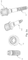
- Fig. 2a shows from left to right a perspective view of dental implant of Fig. 2 , an enlarged perspective view dental implant of Fig. 2 , a perspective view of a tool for insertion 111 of the dental implant of Fig. 2 in the bone a perspective view of the dental implant and the tool as interlocked with each other.
- the enlarged perspective view is taken from a position almost vertical above the dental implant so that the longitudinally extending structures therein appear extremely shortened.
- Fig. 2b shows corresponding perspective views of a modification of the dental implant of Fig. 2 . While the dental implant of Fig. 2 and 2a is a tissue level implant, the dental implant of Fig. 2b is a bone level implant. The internal structure of the longitudinal bore 6 however remains unchanged.
- Fig. 3 shows a dental implant similar to the dental implant of Fig. 2 with the only difference that four additional indentations 10 are provided which are profiled and arranged in the same way as the indentations 10 in Fig. 1 .
- the first anti-rotation feature is constituted by the eight equidistantly arranged indentations 10 and 10'.
- each of the indentations 10, 10' has the same semi-circular profile or contour, however indentations 10' are larger as these are located within protrusions 12. It would also be possible for indentations 10' to have a different profile to indentations 10 as long as the profile shape fitted within projection 12.
- the symmetrical nature of the arrangement of indentations 10, 10' would allow for good, even torque transmission about the axis of the implant even when indentations 10, 10' have different profiles.
- Figs. 2 and 3 have the same inwardly tapered portion 9 described in relation to Fig. 1 , with the indentations 10, 10' of the first anti-rotation feature beginning within this inwardly tapered portion 9.
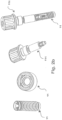
- Fig. 3a shows from left to right a perspective view of the tissue level dental implant of Fig. 3 , an enlarged perspective view of the dental implant of Fig. 3 , a perspective view of a tool for insertion 111 of the dental implant of Fig. 3 in the bone and a perspective view of the dental implant and the tool as interlocked with each other.
- Fig. 3b shows corresponding perspective views of a bone level modification of the dental implant of Figs. 3 and 3a .
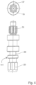
- Fig. 4 shows in more detail the elongate bit tool which is used for insertion of a dental implant as shown in Fig. 3 into the jaw bone of a patient.
- Fig. 4 is scaled down against Fig. 3 , it is seen that the cross section of an implant side tip 16 of the tool occupies almost the whole cross section of the area of the interior bore which bears the anti-rotation structures 10, 10' and 12 in Fig. 3 .
- Eight longitudinally extending projections 18 and 18' are arranged equidistantly at the outer circumference of the implant side tip 16 of the tool.
- the eight projections 18 and 18' engage with the eight indentations 10 and 10' and are in form fit therewith.
- the tool nowhere contacts the projections 12 of the dental implant.
- the tool tip 16 has a constant cross section in the direction of a longitudinal axis of the tool, and the cross section of the tip 16 consists of a square having plane sides and flattened corners extending along the longitudinal axis and of eight longitudinally extending projections 18 and 18' which have a rounded or curved convex profile.
- Each flattened corner of the square bears one of the four projections 18, and each plane side of the square bears one of the projections 18'.
- the four projections 18' would be omitted, and in order to get of a tool tip suited for the dental implant of Fig. 2 , the four projections 18 would be omitted.
- a standard hexagon 20 for engagement by a standard driving tool which is driven manually in order to screw the dental implant into the bone.
- the tool has a necking 22 or reduction in its cross section which forms a breaking point in order to prevent overturning when the dental implant is screwed into the bone.
- Fig. 5 shows a top view from the coronal end and a partial longitudinal section of a dental implant according to a fourth embodiment of the invention.
- This embodiment is similar to the embodiment of Fig. 2 in that indentations 10" are located within the projections 12.
- indentations 10" have not a semi-circular but a triangular profile or contour.
- these are completely contained within the projections, i.e., the indentations do not extend beyond radius r.
- the indentations 10" are formed only in the projections 12 and not in the implant body. This eases manufacture of the two anti-rotation features and strengthens the implant.
- the projections 12 and indentations 10" are completely aligned in the longitudinal direction. It is not possible for the indentations 10" to have a greater longitudinal length than the projections 12 as these do not extend radially beyond r.
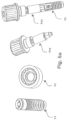
- Fig. 5a shows from left to right a perspective view of the tissue level dental implant of Fig. 5 , an enlarged perspective view of the dental implant of Fig. 5 , a perspective view of a tool for insertion 111 of the dental implant of Fig. 5 in the bone and a perspective view of the dental implant and the tool as interlocked with each other.
- Fig. 5b shows corresponding perspective views of a bone level modification of the dental implant of Figs. 5 and 5a .
- the implant side tip of the tool may have a more simple profile or contour, namely a square profile or contour.
- a dental implant as defined in claim 1.
- the common length along the longitudinal axis amounts to at least the half of the length of longer ones of the anti-rotation structures.
- the anti-rotation structures of the first set have another profile transverse to the longitudinal axis than the anti-rotation structures of the second set.
- the anti-rotation structures of one of the two sets have a rounded or curved profile and the anti-rotation structures of the other set have an angled profile.
- the anti-rotation structures of one of the two sets are broader than the anti-rotation structures of the other set.
- the anti-rotation structures of one of the two sets are projections on the interior bore and the anti-rotation structures of the other set are indentations in the interior bore.
- the anti-rotation structures of the first set and of the second set are arranged equidistantly at the inner circumference of the interior bore.
- the anti-rotation structures of the first set and of the second set are arranged alternating at the inner circumference of the interior bore.
- At least some of the anti-rotation structures of the first set and of the second set are interleaved with each other.
- the anti-rotation structures are formed at the inner circumference of the interior bore by a shaper and/or are hard machined.
- the present invention comprises a dental implant kit comprising at least one dental implant as described herein and a tool for insertion of the dental implant in the bone by engagement into the first set of anti-rotation structures, the tool having a tip which is profiled to occupy almost the whole cross section of an anti-rotation structure-part of the interior bore while being in form fit with the first set of anti-rotation structures.
- the present invention comprises a tool for insertion of a dental implant as described herein, comprising a tool tip with a constant cross section in the direction of a longitudinal axis of the tool, wherein the cross section of the tip consists of a polygon having plane sides and flattened corners extending along the longitudinal axis and of a plurality of longitudinally extending projections which have a rounded or curved convex profile and which are arranged equidistantly at the outer circumference of the tip, wherein each flattened corner of the polygon bears one of the projections and/or each plane side of the polygon bears one of the projections.
- the polygon is a square.
- the tool has a necking which represents a breaking point.
Claims (14)
- Implant dentaire destiné à une insertion dans l'os de mâchoire d'un patient, comportant un corps allongé ayant un axe longitudinal (2) et une extrémité coronaire (4), un alésage intérieur (6) s'étendant longitudinalement depuis l'extrémité coronaire, avec un premier ensemble de structures anti-rotation s'étendant longitudinalement (10, 10') constituant une première caractéristique anti-rotation et un second ensemble de structures anti-rotation s'étendant longitudinalement (12) constituant une seconde caractéristique anti-rotation, les structures anti-rotation du premier ensemble et les structures anti-rotation du second ensemble s'étendant au moins en partie sur une longueur commune de l'alésage, caractérisé en ce que les structures d'au moins le deuxième ensemble de structures anti-rotation sont formées par des saillies sur l'alésage intérieur et dans lequel la longueur commune de l'alésage a une forme cylindrique circulaire et a un rayon r, les saillies s'étendant vers l'intérieur et étant intercalées entre des segments d'alésage ayant le rayon r, dans lequel les structures anti-rotation s'étendant longitudinalement (10, 10', 12) sont formées sur la circonférence intérieure de l'alésage intérieur, la seconde caractéristique anti-rotation étant indépendante de la première caractéristique antirotation, et dans lequel les structures anti-rotation (10, 10') du premier ensemble et les structures antirotation (12) du second ensemble s'étendent en partie sur une longueur commune (a) le long de l'axe longitudinal (2), dans lequel les structures du premier ensemble de structures anti-rotation (10, 10') commencent plus près de l'extrémité coronaire (4) de l'implant que le second ensemble.
- Implant dentaire selon la revendication 1, caractérisé en ce que les structures du premier ensemble de structures anti-rotation (10, 10') s'étendent sur une plus grande longueur de l'alésage longitudinal que le second ensemble de structures anti-rotation (12).
- Implant dentaire selon l'une quelconque des revendications précédentes, dans lequel les structures du second ensemble de structures anti-rotation (12) sont totalement incluses dans le premier ensemble de structures anti-rotation (10, 10').
- Implant dentaire selon l'une quelconque des revendications précédentes, dans lequel la longueur commune (a) le long de l'axe longitudinal (2) s'élève à au moins la moitié de la longueur des plus longues des structures anti-rotation (10, 10', 12).
- Implant dentaire selon l'une quelconque des revendications précédentes, caractérisé en ce que les structures anti-rotation (10, 10') du premier ensemble sont profilées de la même manière transversale à l'axe longitudinal (2) et les structures anti-rotation (12) du second ensemble sont profilées de la même manière transversale à l'axe longitudinal (2), dans lequel les profils des premier et second ensembles de structures antirotation ne sont pas les mêmes.
- Implant dentaire selon l'une quelconque des revendications précédentes, caractérisé en ce que les structures anti-rotation (10, 10') de l'un des deux ensembles ont un profil arrondi ou incurvé et les structures anti-rotation (12) de l'autre ensemble ont un profil incliné.
- Implant dentaire selon l'une quelconque des revendications précédentes, caractérisé en ce que les structures anti-rotation (12) de l'un des deux ensembles sont plus larges que les structures anti-rotation (10, 10') de l'autre ensemble.
- Implant dentaire selon l'une quelconque des revendications précédentes, dans lequel l'alésage (6) comporte, à son extrémité coronaire (4), une surface tronconique s'effilant vers l'intérieur, dans lequel la longueur commune des première et seconde structures antirotation (10, 10', 12) est apicale à cette surface.
- Implant dentaire selon la revendication 8, dans lequel les structures du premier ensemble de structures anti-rotation (10, 10') commencent dans ladite surface tronconique et les structures du second ensemble (12) commencent apicalement à ladite surface tronconique.
- Implant dentaire selon l'une quelconque des revendications précédentes, dans lequel les structures anti-rotation de chaque ensemble sont situées à des intervalles angulaires régulièrement espacés autour de l'axe longitudinal (2).
- Implant dentaire selon l'une des revendications précédentes, caractérisé en ce que les structures anti-rotation du premier ensemble (10, 10') sont formées par des indentations.
- Implant dentaire selon la revendication 11, dans lequel au moins certaines des indentations du premier ensemble sont formées dans les saillies du second ensemble.
- Implant dentaire selon la revendication 11, dans lequel la longueur commune (a) de l'alésage a un rayon r, et dans lequel les structures du premier ensemble de structures anti-rotation (10, 10') comportent des surfaces anti-rotation situées radialement au-delà de r et les structures du second ensemble de structures anti-rotation (12) comportent des surfaces anti-rotation situées à l'intérieur de r.
- Kit d'implant dentaire comportant:un implant dentaire selon l'une quelconque des revendications 1 à 13 etun outil d'insertion pour l'insertion (111) de l'implant dentaire dans l'os, l'outil d'insertion comportant un embout (16) qui est formé pour venir en prise avec le premier ensemble de structures anti-rotation (10, 10'), de telle sorte qu'un couple peut être transmis de l'outil à l'implant via la première caractéristique antirotation, l'embout étant en outre formé de manière à ne pas venir en prise avec le second ensemble de structures anti-rotation de façon à transmettre un couple.
Applications Claiming Priority (4)
| Application Number | Priority Date | Filing Date | Title |
|---|---|---|---|
| EP09168657 | 2009-08-26 | ||
| PCT/EP2010/062454 WO2011023750A2 (fr) | 2009-08-26 | 2010-08-26 | Implant dentaire, procédé de fabrication correspondant, trousse d'implant dentaire et outil pour l'insertion de l'implant dentaire |
| EP10751899.5A EP2470111B1 (fr) | 2009-08-26 | 2010-08-26 | Implant dentaire et équipement avec cet implant dentaire |
| EP13167926.8A EP2662052B1 (fr) | 2009-08-26 | 2010-08-26 | Implant dentaire et kit comprenant ledit implant dentaire |
Related Parent Applications (3)
| Application Number | Title | Priority Date | Filing Date |
|---|---|---|---|
| EP13167926.8A Division-Into EP2662052B1 (fr) | 2009-08-26 | 2010-08-26 | Implant dentaire et kit comprenant ledit implant dentaire |
| EP13167926.8A Division EP2662052B1 (fr) | 2009-08-26 | 2010-08-26 | Implant dentaire et kit comprenant ledit implant dentaire |
| EP10751899.5A Division EP2470111B1 (fr) | 2009-08-26 | 2010-08-26 | Implant dentaire et équipement avec cet implant dentaire |
Publications (3)
| Publication Number | Publication Date |
|---|---|
| EP2946746A1 EP2946746A1 (fr) | 2015-11-25 |
| EP2946746B1 EP2946746B1 (fr) | 2019-11-13 |
| EP2946746B2 true EP2946746B2 (fr) | 2023-06-14 |
Family
ID=41508758
Family Applications (3)
| Application Number | Title | Priority Date | Filing Date |
|---|---|---|---|
| EP10751899.5A Active EP2470111B1 (fr) | 2009-08-26 | 2010-08-26 | Implant dentaire et équipement avec cet implant dentaire |
| EP13167926.8A Active EP2662052B1 (fr) | 2009-08-26 | 2010-08-26 | Implant dentaire et kit comprenant ledit implant dentaire |
| EP15168420.6A Active EP2946746B2 (fr) | 2009-08-26 | 2010-08-26 | Implant dentaire et kit comprenant ledit implant dentaire |
Family Applications Before (2)
| Application Number | Title | Priority Date | Filing Date |
|---|---|---|---|
| EP10751899.5A Active EP2470111B1 (fr) | 2009-08-26 | 2010-08-26 | Implant dentaire et équipement avec cet implant dentaire |
| EP13167926.8A Active EP2662052B1 (fr) | 2009-08-26 | 2010-08-26 | Implant dentaire et kit comprenant ledit implant dentaire |
Country Status (9)
| Country | Link |
|---|---|
| US (1) | US10350033B2 (fr) |
| EP (3) | EP2470111B1 (fr) |
| JP (1) | JP5722896B2 (fr) |
| KR (1) | KR101699361B1 (fr) |
| AU (1) | AU2010288519A1 (fr) |
| BR (2) | BR122019018224B8 (fr) |
| CA (1) | CA2772003A1 (fr) |
| ES (3) | ES2431392T3 (fr) |
| WO (1) | WO2011023750A2 (fr) |
Families Citing this family (18)
| Publication number | Priority date | Publication date | Assignee | Title |
|---|---|---|---|---|
| CA2764079A1 (fr) * | 2011-01-20 | 2012-07-20 | Straumann Holding Ag | Ensemble d'implant dentaire et outil d'insertion |
| GB2495513A (en) * | 2011-10-12 | 2013-04-17 | Nobel Biocare Ab | Dental screw and driver |
| CN103648431B (zh) | 2011-07-06 | 2017-05-17 | 诺贝尔生物服务公司 | 螺钉和驱动器的组合件 |
| EP2570095A1 (fr) * | 2011-09-14 | 2013-03-20 | Dentsply IH AB | Composant dentaire et implant dentaire |
| EP2570097A1 (fr) | 2011-09-14 | 2013-03-20 | Dentsply IH AB | Composant dentaire, fixation dentaire et implant dentaire |
| US9468507B2 (en) * | 2012-10-02 | 2016-10-18 | Straumann Holding Ag | Insertion tool |
| GB2509739A (en) | 2013-01-11 | 2014-07-16 | Nobel Biocare Services Ag | Dental drill bit with spherical head and helical fluting |
| US9757214B2 (en) * | 2013-06-10 | 2017-09-12 | Straumann Holding Ag | Dental implant socket arrangement with annular recess |
| CN105283147B (zh) * | 2013-06-10 | 2019-10-15 | 施特劳曼控股股份公司 | 牙科植入物和插入工具 |
| US11045286B2 (en) | 2014-04-22 | 2021-06-29 | Noga Medical Products Ltd. | Dental implants |
| EP3265020B1 (fr) * | 2015-03-04 | 2020-06-10 | Tav - Medical Ltd. | Ensemble d'installation d'implant dentaire |
| CN108601635B (zh) * | 2016-01-29 | 2021-10-08 | 诺贝尔生物服务公司 | 牙种植体、用于牙种植体的插入工具及牙种植体与插入工具的组合 |
| USD817493S1 (en) * | 2016-02-23 | 2018-05-08 | EBI Inc. | Removing apparatus of abutment for dental implant |
| EP3450003A1 (fr) | 2017-08-31 | 2019-03-06 | Sulzer Mixpac AG | Mélangeur dynamique, unité de mélange automatique et procédé d'installation et d'entraînement d'un mélangeur dynamique |
| KR102096885B1 (ko) * | 2017-12-04 | 2020-04-03 | 주식회사 메가젠임플란트 | 치과용 임플란트의 픽스츄어 |
| ES2782673B2 (es) | 2019-02-26 | 2021-09-20 | Gt Medical S L | Interfase dental con modo de ajuste reversible |
| KR102304071B1 (ko) * | 2020-12-30 | 2021-09-24 | 오스템임플란트 주식회사 | 치과용 임플란트 픽스쳐 |
| KR102304081B1 (ko) * | 2020-12-30 | 2021-09-24 | 오스템임플란트 주식회사 | 임플란트용 어버트먼트, 및 이 어버트먼트와 픽스쳐의 결합구조 |
Citations (1)
| Publication number | Priority date | Publication date | Assignee | Title |
|---|---|---|---|---|
| US5810590A (en) † | 1995-01-30 | 1998-09-22 | Fried; Paula S. | Dental implants and methods for extending service life |
Family Cites Families (42)
| Publication number | Priority date | Publication date | Assignee | Title |
|---|---|---|---|---|
| US2082748A (en) * | 1936-12-15 | 1937-06-01 | Continental Screw Company | Combined socket and slotted screw |
| US3584667A (en) * | 1966-09-19 | 1971-06-15 | Textron Inc | Coupling arrangement and tools for same |
| US3841371A (en) * | 1968-07-30 | 1974-10-15 | Microdot Inc | Lock nut |
| JPS55132409A (en) * | 1979-04-03 | 1980-10-15 | Miyagawa Kinzoku Kogyo | Screw and its forming jig |
| US4459074A (en) * | 1981-12-15 | 1984-07-10 | Russell, Burdsall & Ward Corporation | Socket drive |
| GB2199626B (en) * | 1987-01-08 | 1991-09-04 | Core Vent Corp | Screw-type dental implant anchor |
| US5076788A (en) * | 1988-10-05 | 1991-12-31 | Core-Vent Corporation | Grooved, cylindrical dental implant anchoring means |
| JPH0737805B2 (ja) * | 1992-11-17 | 1995-04-26 | 有限会社新城製作所 | 凹部付きねじ及びそのドライバビット |
| US5456267A (en) * | 1994-03-18 | 1995-10-10 | Stark; John G. | Bone marrow harvesting systems and methods and bone biopsy systems and methods |
| WO1997015762A1 (fr) * | 1995-10-27 | 1997-05-01 | Toshiji Yamamoto | Element de transmission de couple |
| US5904483A (en) * | 1995-11-17 | 1999-05-18 | Wade; Curtis K. | Dental implant systems and methods |
| US5674036A (en) * | 1995-12-20 | 1997-10-07 | Hsieh; Chih-Ching | Screw |
| BR9809683A (pt) * | 1997-05-24 | 2000-10-03 | Friadent Gmbh | Implante dentário e dispositivo com um implante dentário |
| US6158310A (en) * | 1999-05-24 | 2000-12-12 | Textron Inc. | Drive system having a strengthened drive system member for resisting torsional stresses |
| FR2809781B1 (fr) * | 2000-06-06 | 2003-01-03 | Gfi Aerospace | Organe de fixation a empreinte d'extremite dans une partie terminale filetee |
| US6626067B1 (en) * | 2000-09-27 | 2003-09-30 | Snap-On Technologies, Inc. | Retention socket geometry variations |
| US20030059276A1 (en) * | 2001-09-26 | 2003-03-27 | Chen Chin Sun | Screw socket opening for receiving various tool bits |
| US6685412B2 (en) * | 2001-10-19 | 2004-02-03 | Cross Medical Products, Inc. | Multi-lobe torque driving recess and tool in particular for an orthopedic implant screw |
| USD470939S1 (en) | 2002-03-01 | 2003-02-25 | Fereidoun Daftary | Anatomic implant with a beveled edge |
| US6575057B1 (en) * | 2002-04-18 | 2003-06-10 | Lisle Corporation | Broken heater hose coupler removal tool and method of use |
| US7112024B2 (en) * | 2002-08-30 | 2006-09-26 | Whitesell International Corporation | Self-attaching nut |
| EP1396236A1 (fr) | 2002-09-06 | 2004-03-10 | Leone S.p.A. | Un implant dentaire et kit correspondant |
| IL190642A (en) | 2002-11-13 | 2011-06-30 | Biomet 3I Llc | Dental implant system |
| EP1608284A4 (fr) * | 2003-03-13 | 2007-05-02 | Young Ku Heo | Procede de traitement d'une prothese retenue par vis et ciment, butee et implant pour une prothese retenue par vis et ciment |
| US7713285B1 (en) * | 2003-07-02 | 2010-05-11 | Biomet Sports Medicine, Llc | Method and apparatus for suture anchors with a vertical eyelet |
| US20050136380A1 (en) | 2003-12-19 | 2005-06-23 | Niznick Gerald A. | Endosseous dental implant |
| US7771459B2 (en) * | 2004-06-07 | 2010-08-10 | Degima Gmbh | Fastener having torque optimized head |
| US7108510B2 (en) * | 2004-06-25 | 2006-09-19 | Niznick Gerald A | Endosseous dental implant |
| JP4818598B2 (ja) * | 2004-09-10 | 2011-11-16 | 株式会社ジーシー | スクリュー型インプラント用フィクスチャー |
| DE102005005402B4 (de) * | 2005-02-05 | 2011-02-17 | Friadent Gmbh | Dentalimplantat sowie Implantatsystem |
| US7225710B2 (en) * | 2005-05-27 | 2007-06-05 | Synthes Gmbh | Combination driver and combination fastener |
| US7188554B2 (en) * | 2005-06-09 | 2007-03-13 | Atlas Spine, Inc. | Medical fastener and tool |
| US20070037121A1 (en) * | 2005-08-10 | 2007-02-15 | Carter Robert D | Carry and drive device and method for dental implant and/or components thereof |
| DE202005014637U1 (de) | 2005-09-15 | 2005-12-08 | Ak-Tek Gmbh | Zweiphasiges Kieferimplantat |
| US20070059666A1 (en) * | 2005-09-15 | 2007-03-15 | Albert Zickman | Dental implant system |
| USD556907S1 (en) | 2006-02-21 | 2007-12-04 | Jeff Rassoli | Dental prosthesis implant |
| ES2315100B1 (es) * | 2006-05-23 | 2010-01-05 | Vogul, S.L. | Implante dental de cono interno. |
| KR101173964B1 (ko) * | 2006-12-14 | 2012-08-16 | 프리아덴트 게엠베하 | 임플란트 삽입 용 장치 |
| US9095397B2 (en) | 2006-12-14 | 2015-08-04 | Friadent Gmbh | Arrangement for insertion of implants |
| US8038442B2 (en) | 2007-04-23 | 2011-10-18 | Nobel Biocare Services Ag | Dental implant and dental component connection |
| ITGE20080054A1 (it) * | 2008-06-11 | 2009-12-12 | Alberto Rebaudi | Impianto per il fissaggio di protesi dentarie |
| US8291795B2 (en) * | 2010-03-02 | 2012-10-23 | Phillips Screw Company | Fastener system with stable engagement and stick fit |
-
2010
- 2010-08-26 EP EP10751899.5A patent/EP2470111B1/fr active Active
- 2010-08-26 ES ES10751899T patent/ES2431392T3/es active Active
- 2010-08-26 ES ES13167926.8T patent/ES2543023T3/es active Active
- 2010-08-26 BR BR122019018224A patent/BR122019018224B8/pt active IP Right Grant
- 2010-08-26 US US13/391,945 patent/US10350033B2/en active Active
- 2010-08-26 BR BR112012004135-5A patent/BR112012004135B1/pt active IP Right Grant
- 2010-08-26 JP JP2012526054A patent/JP5722896B2/ja active Active
- 2010-08-26 WO PCT/EP2010/062454 patent/WO2011023750A2/fr active Application Filing
- 2010-08-26 EP EP13167926.8A patent/EP2662052B1/fr active Active
- 2010-08-26 EP EP15168420.6A patent/EP2946746B2/fr active Active
- 2010-08-26 ES ES15168420T patent/ES2768578T5/es active Active
- 2010-08-26 KR KR1020127007083A patent/KR101699361B1/ko active IP Right Grant
- 2010-08-26 CA CA2772003A patent/CA2772003A1/fr not_active Abandoned
- 2010-08-26 AU AU2010288519A patent/AU2010288519A1/en not_active Abandoned
Patent Citations (1)
| Publication number | Priority date | Publication date | Assignee | Title |
|---|---|---|---|---|
| US5810590A (en) † | 1995-01-30 | 1998-09-22 | Fried; Paula S. | Dental implants and methods for extending service life |
Also Published As
| Publication number | Publication date |
|---|---|
| AU2010288519A1 (en) | 2012-03-15 |
| ES2543023T3 (es) | 2015-08-14 |
| KR101699361B1 (ko) | 2017-01-24 |
| JP5722896B2 (ja) | 2015-05-27 |
| BR112012004135B1 (pt) | 2019-11-19 |
| BR122019018224B1 (pt) | 2020-12-01 |
| WO2011023750A2 (fr) | 2011-03-03 |
| EP2662052A2 (fr) | 2013-11-13 |
| KR20120075462A (ko) | 2012-07-06 |
| US20120196247A1 (en) | 2012-08-02 |
| JP2013502959A (ja) | 2013-01-31 |
| BR122019018224B8 (pt) | 2021-06-22 |
| US10350033B2 (en) | 2019-07-16 |
| EP2662052B1 (fr) | 2015-07-08 |
| EP2470111A2 (fr) | 2012-07-04 |
| ES2768578T3 (es) | 2020-06-23 |
| WO2011023750A3 (fr) | 2011-04-21 |
| ES2431392T3 (es) | 2013-11-26 |
| BR112012004135A2 (pt) | 2016-03-22 |
| ES2768578T5 (es) | 2023-11-02 |
| EP2662052A3 (fr) | 2013-12-04 |
| EP2946746A1 (fr) | 2015-11-25 |
| CA2772003A1 (fr) | 2011-03-03 |
| EP2946746B1 (fr) | 2019-11-13 |
| EP2470111B1 (fr) | 2013-07-17 |
Similar Documents
| Publication | Publication Date | Title |
|---|---|---|
| EP2946746B2 (fr) | Implant dentaire et kit comprenant ledit implant dentaire | |
| JP7289877B2 (ja) | 歯科インプラント、歯科インプラントのための埋入ツール、ならびに歯科インプラントと埋入ツールの組み合わせ | |
| KR102132048B1 (ko) | 삽입 공구 | |
| EP2647349B3 (fr) | Dispositif de fixation d'un implant dentaire | |
| ES2847954T3 (es) | Tornillo para madera con saliente en forma de arco entre filetes de rosca | |
| EP1765214B1 (fr) | Implant dentaire intraosseux | |
| EP3107482B1 (fr) | Implant dentaire | |
| JP6084978B2 (ja) | 歯科用構成要素、歯科用フィクスチャー、および歯科用インプラント | |
| RU2615078C2 (ru) | Зубной компонент и зубной имплантат | |
| US8167613B2 (en) | Screw-type implant, particularly for orthodontics | |
| EP2593033B1 (fr) | Implant dentaire et butée dentaire destinée à être connectée à cet implant dentaire | |
| CN103118624A (zh) | 植入物、植入体、基台体 | |
| KR20160099603A (ko) | 에노살 단일 치아 임플란트 | |
| EP0260446B1 (fr) | Pivot dentaire profilé | |
| US20170172706A1 (en) | Dental post designed for improved crown bonding and reduced root damage | |
| US20080280254A1 (en) | Molar Implant and Method | |
| WO2010105965A1 (fr) | Implant dentaire à introduction axiale destiné à fournir une distraction de crête | |
| KR100422989B1 (ko) | 치과용 래치의 리머탭 | |
| JP2006075427A (ja) | スクリュー型インプラント用フィクスチャー | |
| KR101935504B1 (ko) | 일정 토크값을 갖는 임플란트 스크류 | |
| US20170143459A1 (en) | Dental post designed for increased strength and reduced root damage |
Legal Events
| Date | Code | Title | Description |
|---|---|---|---|
| PUAI | Public reference made under article 153(3) epc to a published international application that has entered the european phase |
Free format text: ORIGINAL CODE: 0009012 |
|
| AC | Divisional application: reference to earlier application |
Ref document number: 2470111 Country of ref document: EP Kind code of ref document: P Ref document number: 2662052 Country of ref document: EP Kind code of ref document: P |
|
| AK | Designated contracting states |
Kind code of ref document: A1 Designated state(s): AL AT BE BG CH CY CZ DE DK EE ES FI FR GB GR HR HU IE IS IT LI LT LU LV MC MK MT NL NO PL PT RO SE SI SK SM TR |
|
| 17P | Request for examination filed |
Effective date: 20160518 |
|
| RBV | Designated contracting states (corrected) |
Designated state(s): AL AT BE BG CH CY CZ DE DK EE ES FI FR GB GR HR HU IE IS IT LI LT LU LV MC MK MT NL NO PL PT RO SE SI SK SM TR |
|
| 17Q | First examination report despatched |
Effective date: 20160926 |
|
| STAA | Information on the status of an ep patent application or granted ep patent |
Free format text: STATUS: EXAMINATION IS IN PROGRESS |
|
| GRAP | Despatch of communication of intention to grant a patent |
Free format text: ORIGINAL CODE: EPIDOSNIGR1 |
|
| STAA | Information on the status of an ep patent application or granted ep patent |
Free format text: STATUS: GRANT OF PATENT IS INTENDED |
|
| INTG | Intention to grant announced |
Effective date: 20190531 |
|
| GRAS | Grant fee paid |
Free format text: ORIGINAL CODE: EPIDOSNIGR3 |
|
| GRAA | (expected) grant |
Free format text: ORIGINAL CODE: 0009210 |
|
| STAA | Information on the status of an ep patent application or granted ep patent |
Free format text: STATUS: THE PATENT HAS BEEN GRANTED |
|
| AC | Divisional application: reference to earlier application |
Ref document number: 2662052 Country of ref document: EP Kind code of ref document: P Ref document number: 2470111 Country of ref document: EP Kind code of ref document: P |
|
| AK | Designated contracting states |
Kind code of ref document: B1 Designated state(s): AL AT BE BG CH CY CZ DE DK EE ES FI FR GB GR HR HU IE IS IT LI LT LU LV MC MK MT NL NO PL PT RO SE SI SK SM TR |
|
| REG | Reference to a national code |
Ref country code: CH Ref legal event code: EP Ref country code: AT Ref legal event code: REF Ref document number: 1200880 Country of ref document: AT Kind code of ref document: T Effective date: 20191115 |
|
| REG | Reference to a national code |
Ref country code: DE Ref legal event code: R096 Ref document number: 602010061991 Country of ref document: DE |
|
| REG | Reference to a national code |
Ref country code: IE Ref legal event code: FG4D |
|
| REG | Reference to a national code |
Ref country code: NL Ref legal event code: MP Effective date: 20191113 |
|
| REG | Reference to a national code |
Ref country code: LT Ref legal event code: MG4D |
|
| PG25 | Lapsed in a contracting state [announced via postgrant information from national office to epo] |
Ref country code: NL Free format text: LAPSE BECAUSE OF FAILURE TO SUBMIT A TRANSLATION OF THE DESCRIPTION OR TO PAY THE FEE WITHIN THE PRESCRIBED TIME-LIMIT Effective date: 20191113 Ref country code: LV Free format text: LAPSE BECAUSE OF FAILURE TO SUBMIT A TRANSLATION OF THE DESCRIPTION OR TO PAY THE FEE WITHIN THE PRESCRIBED TIME-LIMIT Effective date: 20191113 Ref country code: SE Free format text: LAPSE BECAUSE OF FAILURE TO SUBMIT A TRANSLATION OF THE DESCRIPTION OR TO PAY THE FEE WITHIN THE PRESCRIBED TIME-LIMIT Effective date: 20191113 Ref country code: PT Free format text: LAPSE BECAUSE OF FAILURE TO SUBMIT A TRANSLATION OF THE DESCRIPTION OR TO PAY THE FEE WITHIN THE PRESCRIBED TIME-LIMIT Effective date: 20200313 Ref country code: NO Free format text: LAPSE BECAUSE OF FAILURE TO SUBMIT A TRANSLATION OF THE DESCRIPTION OR TO PAY THE FEE WITHIN THE PRESCRIBED TIME-LIMIT Effective date: 20200213 Ref country code: GR Free format text: LAPSE BECAUSE OF FAILURE TO SUBMIT A TRANSLATION OF THE DESCRIPTION OR TO PAY THE FEE WITHIN THE PRESCRIBED TIME-LIMIT Effective date: 20200214 Ref country code: LT Free format text: LAPSE BECAUSE OF FAILURE TO SUBMIT A TRANSLATION OF THE DESCRIPTION OR TO PAY THE FEE WITHIN THE PRESCRIBED TIME-LIMIT Effective date: 20191113 Ref country code: PL Free format text: LAPSE BECAUSE OF FAILURE TO SUBMIT A TRANSLATION OF THE DESCRIPTION OR TO PAY THE FEE WITHIN THE PRESCRIBED TIME-LIMIT Effective date: 20191113 Ref country code: BG Free format text: LAPSE BECAUSE OF FAILURE TO SUBMIT A TRANSLATION OF THE DESCRIPTION OR TO PAY THE FEE WITHIN THE PRESCRIBED TIME-LIMIT Effective date: 20200213 Ref country code: FI Free format text: LAPSE BECAUSE OF FAILURE TO SUBMIT A TRANSLATION OF THE DESCRIPTION OR TO PAY THE FEE WITHIN THE PRESCRIBED TIME-LIMIT Effective date: 20191113 |
|
| PG25 | Lapsed in a contracting state [announced via postgrant information from national office to epo] |
Ref country code: HR Free format text: LAPSE BECAUSE OF FAILURE TO SUBMIT A TRANSLATION OF THE DESCRIPTION OR TO PAY THE FEE WITHIN THE PRESCRIBED TIME-LIMIT Effective date: 20191113 Ref country code: IS Free format text: LAPSE BECAUSE OF FAILURE TO SUBMIT A TRANSLATION OF THE DESCRIPTION OR TO PAY THE FEE WITHIN THE PRESCRIBED TIME-LIMIT Effective date: 20200313 |
|
| REG | Reference to a national code |
Ref country code: ES Ref legal event code: FG2A Ref document number: 2768578 Country of ref document: ES Kind code of ref document: T3 Effective date: 20200623 |
|
| PG25 | Lapsed in a contracting state [announced via postgrant information from national office to epo] |
Ref country code: AL Free format text: LAPSE BECAUSE OF FAILURE TO SUBMIT A TRANSLATION OF THE DESCRIPTION OR TO PAY THE FEE WITHIN THE PRESCRIBED TIME-LIMIT Effective date: 20191113 |
|
| PG25 | Lapsed in a contracting state [announced via postgrant information from national office to epo] |
Ref country code: CZ Free format text: LAPSE BECAUSE OF FAILURE TO SUBMIT A TRANSLATION OF THE DESCRIPTION OR TO PAY THE FEE WITHIN THE PRESCRIBED TIME-LIMIT Effective date: 20191113 Ref country code: RO Free format text: LAPSE BECAUSE OF FAILURE TO SUBMIT A TRANSLATION OF THE DESCRIPTION OR TO PAY THE FEE WITHIN THE PRESCRIBED TIME-LIMIT Effective date: 20191113 Ref country code: DK Free format text: LAPSE BECAUSE OF FAILURE TO SUBMIT A TRANSLATION OF THE DESCRIPTION OR TO PAY THE FEE WITHIN THE PRESCRIBED TIME-LIMIT Effective date: 20191113 Ref country code: EE Free format text: LAPSE BECAUSE OF FAILURE TO SUBMIT A TRANSLATION OF THE DESCRIPTION OR TO PAY THE FEE WITHIN THE PRESCRIBED TIME-LIMIT Effective date: 20191113 |
|
| REG | Reference to a national code |
Ref country code: DE Ref legal event code: R026 Ref document number: 602010061991 Country of ref document: DE |
|
| REG | Reference to a national code |
Ref country code: AT Ref legal event code: MK05 Ref document number: 1200880 Country of ref document: AT Kind code of ref document: T Effective date: 20191113 |
|
| PLBI | Opposition filed |
Free format text: ORIGINAL CODE: 0009260 |
|
| PLAX | Notice of opposition and request to file observation + time limit sent |
Free format text: ORIGINAL CODE: EPIDOSNOBS2 |
|
| PG25 | Lapsed in a contracting state [announced via postgrant information from national office to epo] |
Ref country code: SK Free format text: LAPSE BECAUSE OF FAILURE TO SUBMIT A TRANSLATION OF THE DESCRIPTION OR TO PAY THE FEE WITHIN THE PRESCRIBED TIME-LIMIT Effective date: 20191113 Ref country code: SM Free format text: LAPSE BECAUSE OF FAILURE TO SUBMIT A TRANSLATION OF THE DESCRIPTION OR TO PAY THE FEE WITHIN THE PRESCRIBED TIME-LIMIT Effective date: 20191113 |
|
| 26 | Opposition filed |
Opponent name: NOBEL BIOCARE SERVICES AG Effective date: 20200813 |
|
| PG25 | Lapsed in a contracting state [announced via postgrant information from national office to epo] |
Ref country code: SI Free format text: LAPSE BECAUSE OF FAILURE TO SUBMIT A TRANSLATION OF THE DESCRIPTION OR TO PAY THE FEE WITHIN THE PRESCRIBED TIME-LIMIT Effective date: 20191113 Ref country code: AT Free format text: LAPSE BECAUSE OF FAILURE TO SUBMIT A TRANSLATION OF THE DESCRIPTION OR TO PAY THE FEE WITHIN THE PRESCRIBED TIME-LIMIT Effective date: 20191113 |
|
| PLAF | Information modified related to communication of a notice of opposition and request to file observations + time limit |
Free format text: ORIGINAL CODE: EPIDOSCOBS2 |
|
| PG25 | Lapsed in a contracting state [announced via postgrant information from national office to epo] |
Ref country code: IT Free format text: LAPSE BECAUSE OF FAILURE TO SUBMIT A TRANSLATION OF THE DESCRIPTION OR TO PAY THE FEE WITHIN THE PRESCRIBED TIME-LIMIT Effective date: 20191113 |
|
| PLBB | Reply of patent proprietor to notice(s) of opposition received |
Free format text: ORIGINAL CODE: EPIDOSNOBS3 |
|
| PG25 | Lapsed in a contracting state [announced via postgrant information from national office to epo] |
Ref country code: MC Free format text: LAPSE BECAUSE OF FAILURE TO SUBMIT A TRANSLATION OF THE DESCRIPTION OR TO PAY THE FEE WITHIN THE PRESCRIBED TIME-LIMIT Effective date: 20191113 |
|
| PG25 | Lapsed in a contracting state [announced via postgrant information from national office to epo] |
Ref country code: LU Free format text: LAPSE BECAUSE OF NON-PAYMENT OF DUE FEES Effective date: 20200826 |
|
| REG | Reference to a national code |
Ref country code: BE Ref legal event code: MM Effective date: 20200831 |
|
| PG25 | Lapsed in a contracting state [announced via postgrant information from national office to epo] |
Ref country code: BE Free format text: LAPSE BECAUSE OF NON-PAYMENT OF DUE FEES Effective date: 20200831 Ref country code: IE Free format text: LAPSE BECAUSE OF NON-PAYMENT OF DUE FEES Effective date: 20200826 |
|
| PG25 | Lapsed in a contracting state [announced via postgrant information from national office to epo] |
Ref country code: TR Free format text: LAPSE BECAUSE OF FAILURE TO SUBMIT A TRANSLATION OF THE DESCRIPTION OR TO PAY THE FEE WITHIN THE PRESCRIBED TIME-LIMIT Effective date: 20191113 Ref country code: MT Free format text: LAPSE BECAUSE OF FAILURE TO SUBMIT A TRANSLATION OF THE DESCRIPTION OR TO PAY THE FEE WITHIN THE PRESCRIBED TIME-LIMIT Effective date: 20191113 Ref country code: CY Free format text: LAPSE BECAUSE OF FAILURE TO SUBMIT A TRANSLATION OF THE DESCRIPTION OR TO PAY THE FEE WITHIN THE PRESCRIBED TIME-LIMIT Effective date: 20191113 |
|
| PG25 | Lapsed in a contracting state [announced via postgrant information from national office to epo] |
Ref country code: MK Free format text: LAPSE BECAUSE OF FAILURE TO SUBMIT A TRANSLATION OF THE DESCRIPTION OR TO PAY THE FEE WITHIN THE PRESCRIBED TIME-LIMIT Effective date: 20191113 |
|
| PUAH | Patent maintained in amended form |
Free format text: ORIGINAL CODE: 0009272 |
|
| STAA | Information on the status of an ep patent application or granted ep patent |
Free format text: STATUS: PATENT MAINTAINED AS AMENDED |
|
| 27A | Patent maintained in amended form |
Effective date: 20230614 |
|
| AK | Designated contracting states |
Kind code of ref document: B2 Designated state(s): AL AT BE BG CH CY CZ DE DK EE ES FI FR GB GR HR HU IE IS IT LI LT LU LV MC MK MT NL NO PL PT RO SE SI SK SM TR |
|
| REG | Reference to a national code |
Ref country code: DE Ref legal event code: R102 Ref document number: 602010061991 Country of ref document: DE |
|
| P01 | Opt-out of the competence of the unified patent court (upc) registered |
Effective date: 20230516 |
|
| PGFP | Annual fee paid to national office [announced via postgrant information from national office to epo] |
Ref country code: GB Payment date: 20230822 Year of fee payment: 14 Ref country code: CH Payment date: 20230902 Year of fee payment: 14 |
|
| REG | Reference to a national code |
Ref country code: ES Ref legal event code: DC2A Ref document number: 2768578 Country of ref document: ES Kind code of ref document: T5 Effective date: 20231102 |
|
| PGFP | Annual fee paid to national office [announced via postgrant information from national office to epo] |
Ref country code: FR Payment date: 20230824 Year of fee payment: 14 Ref country code: DE Payment date: 20230821 Year of fee payment: 14 |
|
| PGFP | Annual fee paid to national office [announced via postgrant information from national office to epo] |
Ref country code: ES Payment date: 20231027 Year of fee payment: 14 |