EP2945669B1 - Stiftartiger arzneimittelinjektor mit reibungsarmer dosismessvorrichtung auf einem gewinde - Google Patents
Stiftartiger arzneimittelinjektor mit reibungsarmer dosismessvorrichtung auf einem gewinde Download PDFInfo
- Publication number
- EP2945669B1 EP2945669B1 EP14700373.5A EP14700373A EP2945669B1 EP 2945669 B1 EP2945669 B1 EP 2945669B1 EP 14700373 A EP14700373 A EP 14700373A EP 2945669 B1 EP2945669 B1 EP 2945669B1
- Authority
- EP
- European Patent Office
- Prior art keywords
- sleeve
- thread
- body component
- dose
- contacts
- Prior art date
- Legal status (The legal status is an assumption and is not a legal conclusion. Google has not performed a legal analysis and makes no representation as to the accuracy of the status listed.)
- Active
Links
- 239000003814 drug Substances 0.000 title description 31
- 229940079593 drug Drugs 0.000 title description 28
- 230000007246 mechanism Effects 0.000 title description 28
- 238000002347 injection Methods 0.000 title description 8
- 239000007924 injection Substances 0.000 title description 8
- 238000012377 drug delivery Methods 0.000 claims description 36
- 230000036316 preload Effects 0.000 claims description 16
- 230000008901 benefit Effects 0.000 description 8
- NOESYZHRGYRDHS-UHFFFAOYSA-N insulin Chemical compound N1C(=O)C(NC(=O)C(CCC(N)=O)NC(=O)C(CCC(O)=O)NC(=O)C(C(C)C)NC(=O)C(NC(=O)CN)C(C)CC)CSSCC(C(NC(CO)C(=O)NC(CC(C)C)C(=O)NC(CC=2C=CC(O)=CC=2)C(=O)NC(CCC(N)=O)C(=O)NC(CC(C)C)C(=O)NC(CCC(O)=O)C(=O)NC(CC(N)=O)C(=O)NC(CC=2C=CC(O)=CC=2)C(=O)NC(CSSCC(NC(=O)C(C(C)C)NC(=O)C(CC(C)C)NC(=O)C(CC=2C=CC(O)=CC=2)NC(=O)C(CC(C)C)NC(=O)C(C)NC(=O)C(CCC(O)=O)NC(=O)C(C(C)C)NC(=O)C(CC(C)C)NC(=O)C(CC=2NC=NC=2)NC(=O)C(CO)NC(=O)CNC2=O)C(=O)NCC(=O)NC(CCC(O)=O)C(=O)NC(CCCNC(N)=N)C(=O)NCC(=O)NC(CC=3C=CC=CC=3)C(=O)NC(CC=3C=CC=CC=3)C(=O)NC(CC=3C=CC(O)=CC=3)C(=O)NC(C(C)O)C(=O)N3C(CCC3)C(=O)NC(CCCCN)C(=O)NC(C)C(O)=O)C(=O)NC(CC(N)=O)C(O)=O)=O)NC(=O)C(C(C)CC)NC(=O)C(CO)NC(=O)C(C(C)O)NC(=O)C1CSSCC2NC(=O)C(CC(C)C)NC(=O)C(NC(=O)C(CCC(N)=O)NC(=O)C(CC(N)=O)NC(=O)C(NC(=O)C(N)CC=1C=CC=CC=1)C(C)C)CC1=CN=CN1 NOESYZHRGYRDHS-UHFFFAOYSA-N 0.000 description 6
- 230000008878 coupling Effects 0.000 description 5
- 238000010168 coupling process Methods 0.000 description 5
- 238000005859 coupling reaction Methods 0.000 description 5
- 238000010586 diagram Methods 0.000 description 5
- 238000000034 method Methods 0.000 description 5
- 230000000994 depressogenic effect Effects 0.000 description 4
- 229920006351 engineering plastic Polymers 0.000 description 4
- 239000000463 material Substances 0.000 description 4
- 230000004048 modification Effects 0.000 description 4
- 238000012986 modification Methods 0.000 description 4
- 102000004877 Insulin Human genes 0.000 description 3
- 108090001061 Insulin Proteins 0.000 description 3
- 230000008859 change Effects 0.000 description 3
- 239000002184 metal Substances 0.000 description 3
- 230000008569 process Effects 0.000 description 3
- 239000000758 substrate Substances 0.000 description 3
- 238000010276 construction Methods 0.000 description 2
- 206010012601 diabetes mellitus Diseases 0.000 description 2
- 230000036541 health Effects 0.000 description 2
- 229940125396 insulin Drugs 0.000 description 2
- 238000004519 manufacturing process Methods 0.000 description 2
- WQZGKKKJIJFFOK-GASJEMHNSA-N Glucose Natural products OC[C@H]1OC(O)[C@H](O)[C@@H](O)[C@@H]1O WQZGKKKJIJFFOK-GASJEMHNSA-N 0.000 description 1
- 108010057186 Insulin Glargine Proteins 0.000 description 1
- COCFEDIXXNGUNL-RFKWWTKHSA-N Insulin glargine Chemical compound C([C@@H](C(=O)N[C@@H](CC(C)C)C(=O)N[C@H]1CSSC[C@H]2C(=O)N[C@H](C(=O)N[C@@H](CO)C(=O)N[C@H](C(=O)N[C@H](C(N[C@@H](CO)C(=O)N[C@@H](CC(C)C)C(=O)N[C@@H](CC=3C=CC(O)=CC=3)C(=O)N[C@@H](CCC(N)=O)C(=O)N[C@@H](CC(C)C)C(=O)N[C@@H](CCC(O)=O)C(=O)N[C@@H](CC(N)=O)C(=O)N[C@@H](CC=3C=CC(O)=CC=3)C(=O)N[C@@H](CSSC[C@H](NC(=O)[C@H](C(C)C)NC(=O)[C@H](CC(C)C)NC(=O)[C@H](CC=3C=CC(O)=CC=3)NC(=O)[C@H](CC(C)C)NC(=O)[C@H](C)NC(=O)[C@H](CCC(O)=O)NC(=O)[C@H](C(C)C)NC(=O)[C@H](CC(C)C)NC(=O)[C@H](CC=3NC=NC=3)NC(=O)[C@H](CO)NC(=O)CNC1=O)C(=O)NCC(=O)N[C@@H](CCC(O)=O)C(=O)N[C@@H](CCCNC(N)=N)C(=O)NCC(=O)N[C@@H](CC=1C=CC=CC=1)C(=O)N[C@@H](CC=1C=CC=CC=1)C(=O)N[C@@H](CC=1C=CC(O)=CC=1)C(=O)N[C@@H]([C@@H](C)O)C(=O)N1[C@@H](CCC1)C(=O)N[C@@H](CCCCN)C(=O)N[C@@H]([C@@H](C)O)C(=O)N[C@@H](CCCNC(N)=N)C(=O)N[C@@H](CCCNC(N)=N)C(O)=O)C(=O)NCC(O)=O)=O)CSSC[C@@H](C(N2)=O)NC(=O)[C@H](CCC(N)=O)NC(=O)[C@H](CCC(O)=O)NC(=O)[C@H](C(C)C)NC(=O)[C@@H](NC(=O)CN)[C@@H](C)CC)[C@@H](C)CC)[C@@H](C)O)NC(=O)[C@H](CCC(N)=O)NC(=O)[C@H](CC(N)=O)NC(=O)[C@@H](NC(=O)[C@@H](N)CC=1C=CC=CC=1)C(C)C)C1=CN=CN1 COCFEDIXXNGUNL-RFKWWTKHSA-N 0.000 description 1
- DHKHKXVYLBGOIT-UHFFFAOYSA-N acetaldehyde Diethyl Acetal Natural products CCOC(C)OCC DHKHKXVYLBGOIT-UHFFFAOYSA-N 0.000 description 1
- 125000002777 acetyl group Chemical class [H]C([H])([H])C(*)=O 0.000 description 1
- 239000000853 adhesive Substances 0.000 description 1
- 230000001070 adhesive effect Effects 0.000 description 1
- 238000013459 approach Methods 0.000 description 1
- 239000008280 blood Substances 0.000 description 1
- 210000004369 blood Anatomy 0.000 description 1
- 230000003139 buffering effect Effects 0.000 description 1
- 238000006243 chemical reaction Methods 0.000 description 1
- 230000000694 effects Effects 0.000 description 1
- 230000005611 electricity Effects 0.000 description 1
- 230000006870 function Effects 0.000 description 1
- 239000008103 glucose Substances 0.000 description 1
- 230000002641 glycemic effect Effects 0.000 description 1
- 238000001746 injection moulding Methods 0.000 description 1
- 229960001382 insulin argine Drugs 0.000 description 1
- 229960002869 insulin glargine Drugs 0.000 description 1
- 239000007788 liquid Substances 0.000 description 1
- 238000007726 management method Methods 0.000 description 1
- 238000005259 measurement Methods 0.000 description 1
- 229940126601 medicinal product Drugs 0.000 description 1
- 230000003287 optical effect Effects 0.000 description 1
- 238000007747 plating Methods 0.000 description 1
- 238000003825 pressing Methods 0.000 description 1
- 238000005070 sampling Methods 0.000 description 1
- 239000000126 substance Substances 0.000 description 1
- 238000012549 training Methods 0.000 description 1
- 230000007704 transition Effects 0.000 description 1
Images


Classifications
-
- A—HUMAN NECESSITIES
- A61—MEDICAL OR VETERINARY SCIENCE; HYGIENE
- A61M—DEVICES FOR INTRODUCING MEDIA INTO, OR ONTO, THE BODY; DEVICES FOR TRANSDUCING BODY MEDIA OR FOR TAKING MEDIA FROM THE BODY; DEVICES FOR PRODUCING OR ENDING SLEEP OR STUPOR
- A61M5/00—Devices for bringing media into the body in a subcutaneous, intra-vascular or intramuscular way; Accessories therefor, e.g. filling or cleaning devices, arm-rests
- A61M5/178—Syringes
- A61M5/31—Details
- A61M5/315—Pistons; Piston-rods; Guiding, blocking or restricting the movement of the rod or piston; Appliances on the rod for facilitating dosing ; Dosing mechanisms
- A61M5/31565—Administration mechanisms, i.e. constructional features, modes of administering a dose
- A61M5/31566—Means improving security or handling thereof
- A61M5/31568—Means keeping track of the total dose administered, e.g. since the cartridge was inserted
-
- A—HUMAN NECESSITIES
- A61—MEDICAL OR VETERINARY SCIENCE; HYGIENE
- A61M—DEVICES FOR INTRODUCING MEDIA INTO, OR ONTO, THE BODY; DEVICES FOR TRANSDUCING BODY MEDIA OR FOR TAKING MEDIA FROM THE BODY; DEVICES FOR PRODUCING OR ENDING SLEEP OR STUPOR
- A61M5/00—Devices for bringing media into the body in a subcutaneous, intra-vascular or intramuscular way; Accessories therefor, e.g. filling or cleaning devices, arm-rests
- A61M5/178—Syringes
- A61M5/31—Details
- A61M5/315—Pistons; Piston-rods; Guiding, blocking or restricting the movement of the rod or piston; Appliances on the rod for facilitating dosing ; Dosing mechanisms
- A61M5/31511—Piston or piston-rod constructions, e.g. connection of piston with piston-rod
- A61M5/31513—Piston constructions to improve sealing or sliding
-
- A—HUMAN NECESSITIES
- A61—MEDICAL OR VETERINARY SCIENCE; HYGIENE
- A61M—DEVICES FOR INTRODUCING MEDIA INTO, OR ONTO, THE BODY; DEVICES FOR TRANSDUCING BODY MEDIA OR FOR TAKING MEDIA FROM THE BODY; DEVICES FOR PRODUCING OR ENDING SLEEP OR STUPOR
- A61M5/00—Devices for bringing media into the body in a subcutaneous, intra-vascular or intramuscular way; Accessories therefor, e.g. filling or cleaning devices, arm-rests
- A61M5/178—Syringes
- A61M5/31—Details
- A61M5/315—Pistons; Piston-rods; Guiding, blocking or restricting the movement of the rod or piston; Appliances on the rod for facilitating dosing ; Dosing mechanisms
- A61M5/31525—Dosing
- A61M5/31528—Dosing by means of rotational movements, e.g. screw-thread mechanisms
-
- A—HUMAN NECESSITIES
- A61—MEDICAL OR VETERINARY SCIENCE; HYGIENE
- A61M—DEVICES FOR INTRODUCING MEDIA INTO, OR ONTO, THE BODY; DEVICES FOR TRANSDUCING BODY MEDIA OR FOR TAKING MEDIA FROM THE BODY; DEVICES FOR PRODUCING OR ENDING SLEEP OR STUPOR
- A61M5/00—Devices for bringing media into the body in a subcutaneous, intra-vascular or intramuscular way; Accessories therefor, e.g. filling or cleaning devices, arm-rests
- A61M5/178—Syringes
- A61M5/31—Details
- A61M5/315—Pistons; Piston-rods; Guiding, blocking or restricting the movement of the rod or piston; Appliances on the rod for facilitating dosing ; Dosing mechanisms
- A61M5/31533—Dosing mechanisms, i.e. setting a dose
- A61M5/31535—Means improving security or handling thereof, e.g. blocking means, means preventing insufficient dosing, means allowing correction of overset dose
-
- A—HUMAN NECESSITIES
- A61—MEDICAL OR VETERINARY SCIENCE; HYGIENE
- A61M—DEVICES FOR INTRODUCING MEDIA INTO, OR ONTO, THE BODY; DEVICES FOR TRANSDUCING BODY MEDIA OR FOR TAKING MEDIA FROM THE BODY; DEVICES FOR PRODUCING OR ENDING SLEEP OR STUPOR
- A61M5/00—Devices for bringing media into the body in a subcutaneous, intra-vascular or intramuscular way; Accessories therefor, e.g. filling or cleaning devices, arm-rests
- A61M5/178—Syringes
- A61M5/31—Details
- A61M5/315—Pistons; Piston-rods; Guiding, blocking or restricting the movement of the rod or piston; Appliances on the rod for facilitating dosing ; Dosing mechanisms
- A61M5/31565—Administration mechanisms, i.e. constructional features, modes of administering a dose
- A61M5/31566—Means improving security or handling thereof
-
- G—PHYSICS
- G01—MEASURING; TESTING
- G01D—MEASURING NOT SPECIALLY ADAPTED FOR A SPECIFIC VARIABLE; ARRANGEMENTS FOR MEASURING TWO OR MORE VARIABLES NOT COVERED IN A SINGLE OTHER SUBCLASS; TARIFF METERING APPARATUS; MEASURING OR TESTING NOT OTHERWISE PROVIDED FOR
- G01D5/00—Mechanical means for transferring the output of a sensing member; Means for converting the output of a sensing member to another variable where the form or nature of the sensing member does not constrain the means for converting; Transducers not specially adapted for a specific variable
- G01D5/12—Mechanical means for transferring the output of a sensing member; Means for converting the output of a sensing member to another variable where the form or nature of the sensing member does not constrain the means for converting; Transducers not specially adapted for a specific variable using electric or magnetic means
- G01D5/14—Mechanical means for transferring the output of a sensing member; Means for converting the output of a sensing member to another variable where the form or nature of the sensing member does not constrain the means for converting; Transducers not specially adapted for a specific variable using electric or magnetic means influencing the magnitude of a current or voltage
- G01D5/16—Mechanical means for transferring the output of a sensing member; Means for converting the output of a sensing member to another variable where the form or nature of the sensing member does not constrain the means for converting; Transducers not specially adapted for a specific variable using electric or magnetic means influencing the magnitude of a current or voltage by varying resistance
- G01D5/165—Mechanical means for transferring the output of a sensing member; Means for converting the output of a sensing member to another variable where the form or nature of the sensing member does not constrain the means for converting; Transducers not specially adapted for a specific variable using electric or magnetic means influencing the magnitude of a current or voltage by varying resistance by relative movement of a point of contact or actuation and a resistive track
-
- G—PHYSICS
- G01—MEASURING; TESTING
- G01F—MEASURING VOLUME, VOLUME FLOW, MASS FLOW OR LIQUID LEVEL; METERING BY VOLUME
- G01F11/00—Apparatus requiring external operation adapted at each repeated and identical operation to measure and separate a predetermined volume of fluid or fluent solid material from a supply or container, without regard to weight, and to deliver it
- G01F11/02—Apparatus requiring external operation adapted at each repeated and identical operation to measure and separate a predetermined volume of fluid or fluent solid material from a supply or container, without regard to weight, and to deliver it with measuring chambers which expand or contract during measurement
- G01F11/021—Apparatus requiring external operation adapted at each repeated and identical operation to measure and separate a predetermined volume of fluid or fluent solid material from a supply or container, without regard to weight, and to deliver it with measuring chambers which expand or contract during measurement of the piston type
- G01F11/023—Apparatus requiring external operation adapted at each repeated and identical operation to measure and separate a predetermined volume of fluid or fluent solid material from a supply or container, without regard to weight, and to deliver it with measuring chambers which expand or contract during measurement of the piston type with provision for varying the stroke of the piston
-
- G—PHYSICS
- G01—MEASURING; TESTING
- G01F—MEASURING VOLUME, VOLUME FLOW, MASS FLOW OR LIQUID LEVEL; METERING BY VOLUME
- G01F11/00—Apparatus requiring external operation adapted at each repeated and identical operation to measure and separate a predetermined volume of fluid or fluent solid material from a supply or container, without regard to weight, and to deliver it
- G01F11/02—Apparatus requiring external operation adapted at each repeated and identical operation to measure and separate a predetermined volume of fluid or fluent solid material from a supply or container, without regard to weight, and to deliver it with measuring chambers which expand or contract during measurement
- G01F11/021—Apparatus requiring external operation adapted at each repeated and identical operation to measure and separate a predetermined volume of fluid or fluent solid material from a supply or container, without regard to weight, and to deliver it with measuring chambers which expand or contract during measurement of the piston type
- G01F11/025—Apparatus requiring external operation adapted at each repeated and identical operation to measure and separate a predetermined volume of fluid or fluent solid material from a supply or container, without regard to weight, and to deliver it with measuring chambers which expand or contract during measurement of the piston type with manually operated pistons
-
- G—PHYSICS
- G01—MEASURING; TESTING
- G01F—MEASURING VOLUME, VOLUME FLOW, MASS FLOW OR LIQUID LEVEL; METERING BY VOLUME
- G01F11/00—Apparatus requiring external operation adapted at each repeated and identical operation to measure and separate a predetermined volume of fluid or fluent solid material from a supply or container, without regard to weight, and to deliver it
- G01F11/02—Apparatus requiring external operation adapted at each repeated and identical operation to measure and separate a predetermined volume of fluid or fluent solid material from a supply or container, without regard to weight, and to deliver it with measuring chambers which expand or contract during measurement
- G01F11/021—Apparatus requiring external operation adapted at each repeated and identical operation to measure and separate a predetermined volume of fluid or fluent solid material from a supply or container, without regard to weight, and to deliver it with measuring chambers which expand or contract during measurement of the piston type
- G01F11/029—Apparatus requiring external operation adapted at each repeated and identical operation to measure and separate a predetermined volume of fluid or fluent solid material from a supply or container, without regard to weight, and to deliver it with measuring chambers which expand or contract during measurement of the piston type provided with electric controlling means
-
- A—HUMAN NECESSITIES
- A61—MEDICAL OR VETERINARY SCIENCE; HYGIENE
- A61M—DEVICES FOR INTRODUCING MEDIA INTO, OR ONTO, THE BODY; DEVICES FOR TRANSDUCING BODY MEDIA OR FOR TAKING MEDIA FROM THE BODY; DEVICES FOR PRODUCING OR ENDING SLEEP OR STUPOR
- A61M2205/00—General characteristics of the apparatus
- A61M2205/33—Controlling, regulating or measuring
- A61M2205/3317—Electromagnetic, inductive or dielectric measuring means
-
- A—HUMAN NECESSITIES
- A61—MEDICAL OR VETERINARY SCIENCE; HYGIENE
- A61M—DEVICES FOR INTRODUCING MEDIA INTO, OR ONTO, THE BODY; DEVICES FOR TRANSDUCING BODY MEDIA OR FOR TAKING MEDIA FROM THE BODY; DEVICES FOR PRODUCING OR ENDING SLEEP OR STUPOR
- A61M5/00—Devices for bringing media into the body in a subcutaneous, intra-vascular or intramuscular way; Accessories therefor, e.g. filling or cleaning devices, arm-rests
- A61M5/178—Syringes
- A61M5/31—Details
- A61M5/315—Pistons; Piston-rods; Guiding, blocking or restricting the movement of the rod or piston; Appliances on the rod for facilitating dosing ; Dosing mechanisms
- A61M5/31533—Dosing mechanisms, i.e. setting a dose
- A61M5/31545—Setting modes for dosing
- A61M5/31548—Mechanically operated dose setting member
- A61M5/3155—Mechanically operated dose setting member by rotational movement of dose setting member, e.g. during setting or filling of a syringe
- A61M5/31551—Mechanically operated dose setting member by rotational movement of dose setting member, e.g. during setting or filling of a syringe including axial movement of dose setting member
Definitions
- the present invention relates to a drug delivery device.
- Pen type drug delivery devices have application where regular injection by persons without formal medical training occurs. This is increasingly common among patients having diabetes where self-treatment enables such patients to conduct effective management of their diabetes. For good or perfect glycemic control, the dose of insulin or insulin glargine has to be adjusted for each individual in accordance with a blood glucose level to be achieved.
- the present invention relates to injectors, for example hand-held injectors, especially pen-type injectors, that is to injectors of the kind that provide for administration by injection of medicinal products from a multidose cartridge. In particular, the present invention relates to such injectors where a user may set the dose. A user undertaking self-administration of insulin will commonly need to administer between 1 and 80 International Units.
- Document US-A-2011/027214 describes an electronically assisted drug delivery device having a Gray code type detector for sensing dosage data.
- a first aspect of the invention provides a drug delivery device comprising:
- Apparatus so constructed can allow determination of the relative position of the sleeve and the body component through detecting the conductive track pattern whilst providing no or relatively little additional resistance to axial movement of the body component relative to the sleeve compared to a corresponding arrangement in which the conductive track and contacts were absent.
- the conductive track pattern may comprise:
- the continuous portion can allow an electrical circuit to be provided with conductive portions of the discontinuous portion.
- the discontinuous portion of the conductive track pattern may be provided on the engaging face of the thread component of the first part and wherein the continuous portion of the conductive track pattern is provided on a non-engaging face of the thread component of the first part. For instance it may be provided on the side face, rather than the top face for the discontinuous part.
- First and second conductive track patterns may be formed on the thread features of the first part and plural contacts are formed on the second part such as to contact the first and second conductive track patterns as the body component rotates within the sleeve.
- the conductive track pattern may alternatively consist of a single conductive track pattern.
- the sleeve thread features may form parts of first and second ones of different start threads and wherein the sleeve thread features and the body component thread features form parts of first and second ones of different start threads.
- the thread features of each thread of the first part may include a conductive track pattern and wherein the thread features of each thread of the second part includes respective plural contacts.
- the body component may constitute the first part and the sleeve may constitute the second part.
- the sleeve may constitute the first part and the body component may constitute the second part.
- Each of the plural contacts may be sprung, thereby to provide a preload force between the sleeve thread features and the body component thread features. This can allow all or part of the preload force to be transferred from the thread features to the longitudinal force that is applied between the sleeve and the body component as they move relative to one another.
- the drug delivery device may further comprise a processor configured to receive and interpret electrical signals from each of the electrical contacts to determine the position of the cylindrical member relative to the housing.
- the device 100 shown in Figure 1 is a pen type injection device, having an elongate cylindrical shape, for setting and delivering a medicament, such as insulin.
- the device 100 comprises a housing 102 having a first housing part 104 and a second housing part 106.
- a rotatable dial 108 is located at a first (or proximal) end of the first housing part 104.
- the rotatable dial 108 has substantially the same outer diameter as the first housing part 104.
- the second housing part 106 may be detachably connected to the second end of the first housing part 104.
- the second housing part 106 is configured to have a needle (not shown) or similar drug delivery apparatus attached to it.
- the second (or distal) end of the second housing part 106 may have a threaded portion 110.
- the threaded portion 110 may have a smaller diameter than the remainder of the second housing part 106.
- a display mount 112 is located on the first housing part 104.
- a display may be supported on the display mount 112.
- the display may be an LCD display, a segmented display or any other suitable type of display.
- the display mount 112 may cover a recess (not shown) in the first housing portion 104.
- a number of electronic components, described in greater detail with reference to Figure 2 may be disposed underneath the display mount 112.
- the first housing part 104 contains a drug dose setting and delivery mechanism.
- the second housing part 106 contains a drug cartridge (not shown).
- the drug contained in the drug cartridge may be a medicament of any kind and may preferably be in a liquid form.
- the drug delivery mechanism of the first housing part 104 may be configured to engage with the drug cartridge of the second housing part 106 to facilitate expulsion of the drug.
- the second housing part 106 may be detached from the first housing part 104 in order to insert a drug cartridge or to remove a used cartridge.
- the first and second housing parts 104, 106 may be connected together in any suitable way, for example with a screw or bayonet type connection.
- the first and second housing parts 104, 106 may be non-reversibly connected together in such a way that the drug cartridge is permanently contained within the drug delivery device 100. Further the first and second housing parts 104, 106 may form part of a single housing part.
- the rotatable dial 108 is configured to be rotated by hand by a user of the drug delivery device 100 in order to set a drug dose to be delivered.
- the dial 108 may be connected to an internal threading system which causes the dial 108 to be displaced axially from the housing 102 as it is rotated in a first direction.
- the dial 108 may be rotatable in both directions or only in a first direction.
- the device 100 is configured, once a drug dose has been set by rotation of the rotatable dial 108, to deliver the set drug dose when a user exerts an axial force at the proximal end of the device.
- the rotatable dial 108 may support a dose delivery button (416 in Figure 3 ) which must be depressed in order to deliver the set drug dose.
- the display 112 may be configured to display information concerning the drug dose which has been set and/or delivered.
- the display 112 may further show additional information, such as the actual time, the time of the last usage/injection, a remaining battery capacity, one or more warning signs indicating that a dialled dose has not been fully dispensed, and/or the like.
- the circuitry 200 comprises a processor 202, a non-volatile memory such as a ROM 204, a writable non-volatile memory such as flash memory 205, a volatile memory such as a RAM 206, a display 210, contacts 212 (described later on as contacts 212a-212i) and a bus 208 connecting each of these components.
- the circuitry 200 also comprises batteries 214 or some other suitable source of power for providing power to each of the components and a switch 216, described in greater detail below.
- the circuitry 200 may be integral with the device 100. Alternatively, the circuitry 200 may be contained within an electronic module that can be attached to the device 100. In addition, the circuitry 200 may comprise additional sensors, such as optical or acoustical sensors. The circuitry 200 may comprise an audible alarm (not shown) which the processor 202 may control to sound an alarm when a dialled dose has not been fully dispensed.
- the ROM 204 may be configured to store software and/or firmware. This software/firmware may control operations of the processor 202.
- the processor 202 utilises RAM 206 to execute the software/firmware stored in the ROM to control operation of the display 210. As such the processor 202 may also comprise a display driver.
- the processor 202 utilises the flash memory 205 to store determined amounts of dose dialled and/or determined amounts of dose dispensed, as will be described in more detail below.
- the batteries 214 may provide power for each of the components including the contacts 212.
- the supply of electricity to the contacts 212 may be controlled by the processor 202.
- the processor 202 may receive signals from the contacts 212 and so could determine when the contacts are energised, and is configured to interpret these signals.
- Information may be provided on the display 210 at suitable times by operation of the software/firmware and the processor 202. This information may include measurements determined from the signals received by the processor 202 from the contacts 212.
- a number of contacts 212 may be present in the device 100, as is described below.
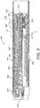
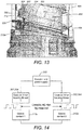
- Figure 3 is a cross-sectional view of a dose setting mechanism 400 of a drug delivery device 100.
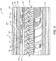
- Figure 4 is a detailed view of a portion of the dose setting mechanism 400.
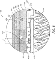
- Figure 5 illustrates a close up view of the region marked 'A' in Figure 3 .
- the dose setting mechanism 400 comprises an outer housing 404, an inner housing 408 and a rotatable sleeve 406.
- the rotatable sleeve 406 is an example of a sleeve.
- the inner housing 408 is an example of a body component. These components are hollow cylinders arranged concentrically.
- the rotatable sleeve 406 is disposed between the outer and inner housings 404, 408.
- the inner housing 408 comprises a groove 432 provided along an external surface 434 of the inner housing 408.
- a groove guide 436 provided on an inner surface 438 of the rotatable sleeve 406 is rotatably engaged with this groove 432.
- a dose dial grip 402 is located at a proximal end of the outer housing 404.
- the dose dial grip 402 is disposed about an outer surface of a proximal end of the rotatable sleeve 406.
- An outer diameter of the dose dial grip 402 preferably corresponds to the outer diameter of the outer housing 404.
- the dose dial grip 402 is secured to the rotatable sleeve 406 to prevent relative movement between these two components.
- the dose dial grip 402 is represented in the external view of Figure 1 by the rotatable dial 108.
- the dose dial grip 402 supports a dose delivery button dose delivery button 416 which has a sprung bias in a proximal direction and is configured to be depressed into the dose dial grip 402 by a user of the device 100.
- a spindle 414 is disposed centrally within the mechanism 400.
- the spindle 414 is provisioned with at least one helical groove.
- the spindle 414 has two opposite handed overlapping groove forms that preferably extend over at least a majority of a length of the spindle. Each groove form is effectively continuous over a number of turns.
- Each groove of the spindle may engage either a non-continuous helical groove form on a body portion or on a driver. Either or both a non-continuous thread formed on a body and a driver may consist of less than one complete turn of thread.
- a first thread of the spindle 414 is configured to connect with a portion of the inner housing 408.
- the dose setting mechanism 400 also comprises a spring 401, a clutch 405 and a driver 409 having a first driver portion 407 and a second driver portion 412. These driver portions 407, 412 extend about the spindle 414. Both the first and the second driver portions 407, 412 are generally cylindrical.
- the clutch 405 is disposed about the driver 409.
- the first driver portion 407 may comprise a first component part 410 and a second component part 411. Alternatively, the first driver portion 407 may be an integral component part.
- the metal spring 401 is selected to be strong enough to maintain engagement of both clutched couplings: the clutched coupling between the clutch 405 and the rotatable sleeve 406 and clutched coupling between the first driver portion 407 and second driver portion 412.
- the rotatable sleeve 406 is coupled to the dose dial grip 402 such that when a user rotates the dose dial grip 402, the rotatable sleeve 406 also rotates. As the rotatable sleeve 406 is rotated in a first rotational direction, it moves axially in a proximal direction due to its threaded connection to the inner housing 408.
- This threaded connection includes a thread feature 436 on the rotatable sleeve 406 and a thread feature 432 on the inner housing 408. These are best viewed in Figure 4 .
- the thread feature 436 on the rotatable sleeve 406 is male (the groove guide) and the thread feature 432 on the inner housing 408 is female (the groove), although alternatively both thread features 432, 436 may be male or the thread feature 436 may be female and the thread feature 432 may be male.
- the user applies an axial load to the dose delivery button 416 located at the proximal end of the mechanism 400.
- the dose delivery button dose delivery button 416 is axially coupled to the clutch 405 and this prevents relative axial movement. Therefore, the clutch 405 moves axially towards the cartridge end or the distal end of the dose setting mechanism 400. This movement disengages the clutch 405 from the rotatable sleeve 406, allowing for relative rotation while closing up the Gap 'a'.
- the clutch 405 is prevented from rotating relative to a clicker 420 and hence relative to the inner housing 408.
- the coupling between the first driver portion 407 and the second driver portion 412 is also prevented from becoming disengaged. Therefore, any axial load on the spindle 414 only disengages the first and second driver portions 407, 412 when the dose delivery button dose delivery button 416 is not axially loaded. This therefore does not happen during dispense.
- a dose limiter 418 (visible in Figure 4 ) is provided on first driver portion 407 and in the illustrated arrangement comprises a nut.
- the dose limiter 418 has an internal helical groove matching the helical groove of the first driver portion 407.
- the outer surface of the dose limiter 418 and an internal surface of the inner housing 408 are keyed together by way of splines. This prevents relative rotation between the dose limiter 418 and the housing 408 while allowing relative longitudinal movement between these two components.
- Figure 6 shows in detail a first arrangement of the first driver portion 407 and the second driver portion 412 illustrated in Figures 3 to 5 .
- the second driver portion 412 is generally tubular in shape and comprises at least one drive dog 450 located at a distal end of the second driver portion 412.
- the first driver portion 407 also has a generally tubular shape and comprises a plurality of recesses 452 sized to engage with the drive dog 450 on the second driver portion 412.
- the construction of the drive dog and recesses allow disengagement with the drive dog 450 when the first and second driver portions are axially pushed together. This construction also creates a rotational coupling when these components are sprung apart.
- the first driver portion 407 comprises a first portion (first component part) 410 that is permanently clipped to a second portion (second component part) 411.
- the second component part 411 comprises the plurality of recesses 452 and the first component part 410 includes the outer groove for the dose limiter 418 nut as well as an internal groove 454.
- This internal groove 454 is used to connect to the spindle 414 and drives the spindle 414 during dose administration.
- the internal groove 454 comprises a part helical groove, which is easier to manufacture than a complete helical groove.
- this dose setting mechanism 400 utilizing the inner housing 408 is that the inner housing 408 can be made from an engineering plastic that minimizes friction relative to the rotatable sleeve 406 groove guide 436 and the groove 432.
- an engineering plastic could comprise Acetal.
- other comparable engineering plastics having a low coefficient of friction could also be used.
- Using such an engineering plastic enables the material for the outer housing 404 to be chosen for aesthetic or tactile reasons with no friction related requirements since the outer housing 404 does not engage any moving components during normal operation.
- the effective driving diameter (represented by 'D') of the grooved interface between the rotatable sleeve 406 and the inner housing 408 is reduced compared to certain known drug delivery devices for the same outer body diameter. This improves efficiency and enables the drug delivery device to function with a lower pitch (represented by 'P') for this groove and groove guide connection.
- 'P' the pitch
- a recess 442 in the outer housing 404 of the drug delivery device 100 can be seen in Figure 3 .
- This recess 442 may be configured to receive an insert or electronic module (not shown), comprising the processor 202, ROM 204, Flash memory 205, RAM 206, display electronics, contacts 212 and batteries 214 previously described.
- the contacts 212 may be supported at another position on the inner surface of the outer housing 404 and linked to the processor 202 and batteries 214 by conductive paths or wires.
- the display mount 112 shown in Figure 1 may be disposed on top of the insert or may be integral with the insert.
- the display mount 112 is configured to support the display 210.
- the display 210 may be larger than the recess 442 and may therefore protrude from the outer housing 404.
- both the display mount 112 and display 210 may be configured to be received by the recess 442 such that the display 210 is flush with the outer surface of the outer housing 404.
- the contacts 212 are configured to contact the rotatable sleeve 406 in order to facilitate a determination of the rotational position of the rotatable sleeve 406, as will be described in more detail below.
- the dose setting mechanism 400 illustrated in Figures 3-6 is configured to be re-set to an initial position after the medicament in the attached drug cartridge has been expelled. This allows a new cartridge to be inserted and the drug delivery device 100 to be re-used. This re-setting may be achieved by pushing axially on the distal end of the spindle 414 i.e. the end which usually engages with the drug cartridge and does not require any mechanism associated with removal of a cartridge holder. As illustrated in Figures 3 and 4 , when the first driver portion 407 is pushed axially towards the second driver portion 412 (i.e., pushed in a proximal direction) the driver 409 is decoupled from the rest of the dose setting mechanism 400.
- This axial movement of the first driver portion 407 towards the second driver portion 412 results in certain advantages.
- one advantage is that the metal spring 401 will compress and will therefore close the Gap 'a' illustrated in Figures 3-5 . This in turn prevents the clutch 405 from disengaging from the clicker 420 or from the rotatable sleeve 406.
- the second driver portion 412 is prevented from rotation since it is splined to the clutch 405.
- the clicker 420 is splined to the inner housing 408. Therefore, when the Gap 'a' is reduced or closed up, the second driver portion 412 cannot rotate relative to either the inner housing 408 or the rotatable sleeve 406.
- the rotatable sleeve 406 cannot rotate relative to the inner housing 404. If the rotatable sleeve 406 is prevented from rotating then, as the spindle 414 is retracted back into the dose setting mechanism 400 and thereby re-set, there will be no risk of the rotatable sleeve 406 being pushed out of the proximal side of the dose setting mechanism 400 as a result of a force being applied on the spindle 414.
- a dose setting mechanism 400 comprising an inner housing 408
- the dose setting mechanism 400 can be designed, with a slight modification, as a drug delivery device platform that is now capable of supporting both re-settable and non-resettable drug delivery devices.
- the first component part 410 and the second component part 411 of the first driver potion 407 and the second driver portion 412 can be moulded as one unitary part. This reduces the total number of drug delivery device components by two. Otherwise, the drug delivery device illustrated in Figures 3-6 could remain unchanged.
- the second housing part 106 would be fixed to the first housing part 104 or alternatively made as a single one piece body and cartridge holder.
- the dose setting mechanism described above is merely one example of a mechanism suitable for supporting the rotatable sleeve 406 and for implementing the present invention. It will be apparent to the skilled person that other mechanisms may also be suitable.
- a user twists the rotatable dial 108 to select an amount of dose to be dispensed from a drug cartridge.
- This causes the rotatable sleeve 406 to rotate and translate axially (longitudinally) relative to the housing 102.
- the extent of rotation of the dial 108, and thus the dose dialled can be determined.
- a user presses the dose delivery button 416 to dispense an amount of dose from within a drug cartridge. Pressing the dose delivery button 416 causes the rotatable sleeve 406 to rotate and move axially the other way.
- the dose dispensed can also be determined.
- a number of schemes for determining an amount of rotation of a sleeve are possible.
- Some possible schemes involve a conductive pattern formed on the cylindrical outside surface of the sleeve.
- electrical contacts mounted in a fixed position relative to the main housing may be caused to contact different parts of the pattern as the sleeve moves within the main housing.
- connection or no connection
- a pattern on an encoder sleeve may be read optically.
- Embodiments of the present invention propose a different scheme.
- a conductive pattern formed on the cylindrical outside surface of the sleeve is not used. Instead, a conductive pattern is formed on an engaging face of thread features of a body component or a sleeve and contacts are provided on the other component.
- Apparatus so constructed can allow determination of the relative position of the sleeve and the body component through detecting the conductive track pattern whilst providing no or relatively little additional resistance to axial movement of the body component relative to the sleeve compared to a corresponding arrangement in which the conductive track and contacts were absent.
- Figure 7 is a view of the whole of the inner housing 408 and Figure 8 is a magnified view of a part of the inner housing.
- a thread feature 432 is clearly visible on the external surface. This thread feature 432 is a twin start thread.
- the thread feature 432 includes three main faces.
- a first face faces upwardly in the figures, and can be called an engaging face 710.
- Opposite the engaging face 710 is a bottom face 714, which is not visible in Figures 7 and 8 because of the angle of view of these figures but are visible in Figure 13 .
- Connecting the engaging face 710 and the bottom face 714 is a side face 712.
- the side face 712 is generally concentric with the main face of the inner housing 408.
- the engaging face 710 and the bottom face 714 may be perpendicular to the axis of the inner housing 408.
- they may be angled slightly, in particular they may be angled such that the angle at the intersection between the engaging face 710 and the side face 712 is slightly greater than 90 degrees, for instance around 95 degrees.
- the angle of intersection between the engaging face 710 and the main external face of the inner housing 408 may be slightly greater than 90 degrees, for instance 95 degrees.
- the first is functional in that the angle acts like a cone to help keep the components concentric and make the designed sections of the threads contact, not the cylindrical surfaces etc.
- the second is that it simplifies manufacturing of the components (e.g. by injection moulding).
- a helical track 300 is provided on the thread feature 432 on the inner housing 408.
- the helical track 300 comprises a number of components. Firstly, a connecting track 306 is provided on the side face 712 of the thread feature 432.
- the connecting track 306 is continuous, that is it is unbroken.
- the helical track 300 includes some features on the engaging face 710 of the thread feature 432 of the inner housing 408. These include alternating conductive segments 302 and non-conductive segments 304.
- the conductive segments 302 are electrically coupled to the connecting track 306, that is located on the side face 712 of the thread feature 432. Successive conductive segments 302 are separated by a non-conductive segment 304. Similarly, successive non-conductive segments 304 are separated by a conductive segment 302.
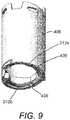
- the contacts 212 form part of the rotatable sleeve 406, as will now be described with reference to Figures 9 to 11 .
- the rotatable sleeve 406 is shown as comprising a generally annular component, with some features at each end. The features at the top end are not of relevance to this explanation, so will not be described.
- thread features 436 At the lowermost end of the rotatable sleeve 406 are provided thread features 436.
- the thread features 436 comprise sections of a twin start thread having the same pitch and direction as the thread components 432 on the inner housing 408.
- the thread features 436 are provided with an engaging face 716, which is downwardly facing in the figures. In use, the engaging face 716 of the thread features 436 of rotatable sleeve 406 is engaged with the engaging face 710 of the thread features 432 of the inner housing 408.
- First and second contacts 212a and 212b are formed on the engaging face 716 of the thread feature 436 of the rotatable sleeve.
- the contacts 212a and 212b are formed on different ones of the twin start threads, so engage with different ones of the twin start threads features 432 of the inner housing 408 in use.
- the contacts 212a, 212b comprise flat-topped protrusions that extend from the generally regular surface that constitutes the engaging face 716 of the thread feature 436 of the rotatable sleeve 406. They may alternatively take the form shown in and described below with reference to Figure 15 .
- a conductive track 220 commences on the face of the contacts 212a, 212b and extends for some distance along the engaging face 716 of the thread feature 436 of the rotatable sleeve 406, before extending off of the engaging face, as is best seen in Figure 11 .
- Figure 12 shows the rotatable sleeve 406 installed on the inner housing 408. From Figure 12 , it can be seen that the rotatable sleeve 406 is considerably shorter than the inner housing 408 so, even when the rotatable sleeve 406 is fully wound onto the inner housing 408 such that it rests at the bottom thereof, a significant part of the inner housing 408 extends out of the top of the rotatable sleeve 406.
- FIG. 13 The relative positions of some of the components of the rotatable sleeve 406 and the inner housing 408 when the components are engaged with one another are shown in Figure 13 .
- the thread feature 436 of the rotatable sleeve 406 corresponds closely with the thread feature 432 of the inner housing 408.
- the engagement of the first contact 212a on the part of the helical track 300 that includes the conductive segments 302 and the non-conductive segments 304 is clearly visible.
- Figure 13 also shows also how the connecting track 220 extends from the exterior of the rotatable sleeve 406 to the first contact 212a.
- the ends of the connectors on the inner housing 408 are accessible through a hole in the outer housing 404 and are electrically connected to the encoder 202 or provide an interconnect for a separable module. Because the inner housing 408 also is fixed to the outer housing 404, the tracks may pass through with a rigid connection to more interconnecting tracks on the housing to pass to the encoder 202 directly or through an interface to a separate module.
- the connecting track 220 on the rotatable sleeve 406 does not connect to the encoder 202, but it does connect the two contacts together.
- the track 220 that is leftmost as shown in Figure 13 runs round the outer diameter to the other contact. This is represented in Figure 14 as the bottom line connecting sleeve contacts 212a and 212b, i.e. not connecting to the encoder 202.
- the contacts 212a and 212b are sprung, as will be described below with reference to Figure 15 .
- the helical tracks 300 shown in Figures 8 to 13 are identical on both threads of the twin start thread feature 432.
- the first and second contacts 212a and 212b are distributed around the circumference of the rotatable sleeve 406, they contact corresponding parts of the helical track 300 on their respective thread.
- the first and second contacts 212a, 212b are either both in contact with a conductive segment 302 of their respective helical track 300 or are both in contact with a non-conductive segment 304 of the helical track 300.
- signals detected by both contacts are identical.
- an encoder and power supply is provided by the processor 202 in conjunction with the battery 214, both of which are shown in Figure 1 .
- a code 302, 304 on a first thread feature 432 of the inner housing 408 is coupled to the first contact 212a on the rotatable sleeve 406 when the contact 212a is aligned with a conductive segment 302. This is represented by a switch between the two components in Figure 14 .
- the code 302, 304 on the second of the twin start thread features 432 connects the contact 212b on the second thread of the rotatable sleeve 406 to the encoder and power supply 202 when a conductive segment 302 is in contact with the contact 212b.
- the height of the thread features 436 on the rotatable sleeve 406 is such that the sprung contacts 212a and 212b provide a pre-load force between the bottom face 714 of one thread feature 432 of the inner housing and the engaging face 710, or uppermost face, of the other thread feature 432 of the inner housing 408.
- this pre-load force provides adequate pressure to the first and second contacts 212a and 212b to achieve electrical connection between the connecting tracks 220 and the helical track 300 when the contacts 212a and 212b coincide with a conductive segment 302 of the helical track 300.
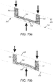
- the contacts 212a and 212b may take the form shown in Figures 15a and 15b . These are schematic figures, but show the functionality provided by the contacts. They show a contact 212 comprising a beam 724 supported at two ends by a first support 720 and a second support 722. A contact pad 726 is supported in the middle of the beam 724 on a face that is opposite to the first and second supports 720, 722. It is the contact pad 726 that contacts the helical track 300 in use.
- Figure 15a shows the contact 212 during a dialling operation.
- a user manipulates the dialling knob 108 to dial in a dose into the injection pen 100.
- the delivery button is not pressed.
- the preload ensures that adequate pressure is applied to the contacts 212 to achieve conductivity with the helical track 300.
- Figure 15b shows the contact 212 during a dose delivery, or dose dispensing, operation.
- the dose delivery button is depressed.
- the thread feature 432 of the inner housing 408 causes the rotatable sleeve 406 to rotate as it travels helically in a distal direction within the main body 102.
- a certain axial force needs to be applied to the inner housing 408 in order to overcome friction between the thread feature 436 of the rotatable sleeve 406 and the thread feature 402 of the inner housing 408 before relative motion will begin.
- the preload force acting on the thread feature 432 of the inner housing 408 and the thread feature 436 of the rotatable sleeve 406 is reduced and this force is instead transferred to the dose delivery button.
- the additional friction resulting from the choice of materials is significant, the friction that would result from having a contact and conductive track arrangement on a cylindrical surface of a rotatable sleeve would be expected to be significantly higher.
- the preload force is less than or equal to the axial force required to rotate the rotatable sleeve 406, the preload force is completely removed during the dispense operation. If the preload force is greater than the dispense force, there is nonetheless a benefit provided by the described arrangement because the axial force during the dispense operation is in effect subtracted from the preload force, giving a lower force than if the preload force was applied independently.
- the helical tracks 300 described above implement an incremental code.
- the track alternates between conductive "high” values and "low” values.
- the encoder 202 counts the number of output changes, namely high to low and low to high, to calculate the dialled dose. This approach has fundamental limitations as the encoder 202 is not able to determine whether the device 100 is dialling or un-dialling a dose. Furthermore, incremental coding is not able to determine if the encoder 202 has failed to register dialled units.
- connecting track 306 of the helical track 300 may be otherwise provided.
- it may be provided on the major face of the inner housing 408, at the part that is closest to the engaging face 710 of the thread feature 432 for example. It may alternatively be provided on the bottom face 714 of the thread feature 432, in which case connecting tracks may extend around the side face 712 to connect the conductive segments 302 on the engaging face 710 with the connecting track 306 on the bottom face 714.
- the thread features 432 and 436 need not be twin start threads. They may alternatively be single start threads, or triple or higher order start threads.
- the inner housing 408 may instead be provided on the innermost surface of the rotatable sleeve 406.
- the inner housing 408 is provided with a thread feature on its outermost surface.
- each of the two thread features 432 of the inner housing 408 is provided with a different helical track 300.
- the thread feature 432 includes a first thread 432a and a second thread 432b.
- a first helical track 300a is formed on the first helical thread feature 432a.
- a second helical track 300b is formed on the second thread feature 432b.
- a first helical power track 301a is formed on the first helical thread feature 432.
- a second helical power track 301b is formed on the second thread feature 432b.
- the power tracks 301a, 301b provide electrical power to the system, and their utility is particularly apparent from Figure 18 .
- each helical track 300a, 300b includes conductive segments 302a and 302b and non-conductive segments 304a and 304b.
- Each helical track 300a, 300b also includes a respective connecting track 306a, 306b.
- the second helical track 300b has the same alternating code as used in the examples above. Where number 1 represents high values and number 0 represents low values, the code of the second helical track 300b may be represented as:
- the first helical track 300a has the following code:
- the code can be read by the circuit shown in Figure 18 .
- the encoder and power supply 202 has four inputs.
- a connection is made between the code 302a, 302b on the first thread feature 432a and a first contact 212a on the rotatable sleeve 406.
- a connection is made back to the encoder 202 by way of the connecting track 220 on the number sleeve and a first power track contact 309, via the connecting track 306a of the helical track 300.
- the power track contact 309 contacts the first power track 301a.
- a circuit is provided to and from the encoder by the conducting and non-conducting segments 302b, 304b of the second helical track 300b to the second contact 212b of the number sleeve 408, via the connecting track 220 on the number sleeve 408 and a second power track contact 310 and the second connecting track 306b of the second helical track 300.
- the second power track contact 310 contacts the second power track 301b.
- the encoder 202 can determine whether the device 100 is dialling or un-dialling. In particular, this can be determined from the direction in which the sequence is moving.
- the encoder 202 may be able to determined that the dialled dose is incorrect. In this case, the device 100 may indicate to the user to restart dialling. A user can perform this by dialling the dose back down to zero and then again commencing the dialling. The system is not completely error proof because a mis-read by a factor of 4 (which is the period of repeat of the code) would seem to the encoder 202 to be correct.
- the code that is provided by the helical tracks 300a, 300b is a conventional binary code, it may instead be provided by a Gray code.
- a Gray code has an advantage that the chances of mis-reading in a transition where two (or more) bits of the code change is reduced. Referring to Figure 17 , for instance, changing between dial position 2 and dial position 3 involves a change of the code from 10 to 01, that is both of the bits change. With a Gray code, conversely, only one of the bits changes when the dial position increments or decrements.
- connecting tracks 306a, 306b of the helical track 300 may be otherwise provided.
- they may be provided on the major face of the inner housing 408, at the part that is closest to the engaging face 710 of the thread feature 432 for instance.
- They may alternatively be provided on the bottom face 714 of the thread feature 432, in which case connecting tracks may extend around the side face 712 to connect the conductive segments 302 on the engaging face 710 with the connecting track 306 on the bottom face 714.
- the thread features 432 and 436 need not be twin start threads. They may alternatively be single start threads, or triple or higher order start threads.
- the inner housing 408 is provided with a thread feature on its outer most surface.
- this need not be continuous, and may be relatively short or may be a number of short sections of partial thread.
- the sleeve 406 that rotates and the inner housing 408 is fixed relative to the main body 102, it may instead be the inner housing 408 that rotates and the sleeve 406 may be fixed relative to the housing 102.
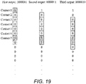
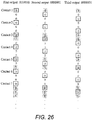
- seven different parts of a code are read by seven different contacts 212. Outputs from the seven contacts 212 are then assembled to produce a seven-bit code by the encoder 202.
- An example of the code is shown below. 100000110000101000011100010010001011000110100011110010011001010 100101110011011001110100
- the code is shown extending down the page. Contacts provided at the first seven consecutive bits in the leftmost column read off a code 1000001. Once the contacts have been incremented, the output read off the code, which is shown in the middle column, is 0000011. After moving one further step, the code read off of the contacts is shown in the right column as 0000110.
- the code is constructed such that the dialled dose can be uniquely identified up to an 80 unit maximum dose by examining signals provided at the contacts 212. Put another way, the signals provided at the contacts 212 uniquely identify a dose in the range of 0 to 80 units.
- the contacts 212 are located at seven consecutive bits of the code, which is formed by the conductive segments 302 and the non-conductive segments 304 of the helical track 300.
- the contacts 212 may be located to contact different parts of the code, some or all of which may be non-consecutive, as is described below with reference to Figure 26 .
- a seven bit code allows determination of a unique number between 0 and 128, which is sufficient for determining a dialled dose in the range of 0 to 80. Having a shorter code, for instance 6, 5 or 4 bits, simplifies the apparatus (at least because there are fewer contacts), although it allows a smaller range of dialled dose units to be uniquely identifiable. Nevertheless, using a shorter code may be preferred in some embodiments.
- the thread feature 436 is provided on the inside surface of the rotatable sleeve 406.
- the thread feature 436 includes three main faces.
- the engaging face 716 is the lowermost face in the figures. This is opposite to the engaging face 716 in the previous embodiment because in this embodiment it is the lowermost face of the thread feature 436 that provides a reactive force against the corresponding thread feature 432 of the inner housing 408, particularly when a dose is being delivered.
- An uppermost face 714 is opposite the engaging face 710. As with the above embodiments, the engaging face 710 and the uppermost face 714 may be angled slightly from perpendicular with the axis of the device 100.
- a side face 712 connects the engaging face 710 and the bottom face 714. The side face 712 is generally concentric with the outer cylindrical surface of the inner housing 408.
- the connecting track 306 of the helical track 300 is provided on the engaging face 710 of the thread feature 432
- the connecting track 306 is shown in the Figures as a very thin connection running along the engaging face 710.
- the conductive segments 302 and non-conductive segments 304 are provided on the engaging face 710, which is the lowermost face, of the thread feature 432.
- the code does not comprise consecutive conductive segments 302 and non-conductive segments 304 of the same length. Instead, some of the conductive segments 302 and the non-conductive segments 304 relate to two or more consecutive bits of the same value.
- the inner housing 408 is provided with contacts 212.
- contacts 212 are provided on the inner housing 408 in contact with the helical track 300.
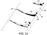
- First to third contacts 212a, 212b and 212c are shown in Figure 22 .
- Also shown in Figure 22 is connecting track 220 that connects the contacts 212a to 212c and other contacts (not shown in the figure because they are on the reverse side of the inner housing 408 as shown) to the bottommost end of the inner housing 408.
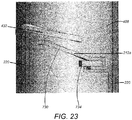
- All of the contacts 212 are substantially the same, and the first contact 212a is shown in detail in Figure 23 .
- a thread feature 432 of the inner housing 408 comprises a part of a thread.
- the thread feature 432 provides a part of a thread that has the same pitch as the thread 436 on the rotatable sleeve 406.
- the contact 212a comprises an arm 730.
- the arm is supported at one end on a support 734.
- the arm 730 is connected to the connecting track 220 at the location of the support 734, in this example on the underside of the support 734.
- the support 734 is provided by a protrusion that extends from the main cylindrical body of the inner housing 408.
- the arm 730 has a free end 732. It is the free end 732 of the arm 730 that contacts the helical track 300 in use.
- the arm 730 is resilient, and is biased into the position shown in Figure 23 .
- the arm 730 may be made of a metal, for instance.
- the arm 730 provides an electrical connection between the connecting tracks 220 and the conductive segments 302 of the helical track 300 in use.
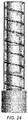
- Figure 24 shows the rotatable sleeve 406 in wireframe located on the inner housing 408.
- the thread feature 432 of the inner housing 408 is engaged with the thread feature 436 of the rotatable sleeve 406.
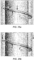
- Figures 25a and 25b Some details of this are shown in Figures 25a and 25b .
- the distance between the thread features 432 and the free end 732 of the arm 730 is such that the contacts 212 provide preload forces acting on the thread features 436 of the rotatable sleeve 406 in use.
- This is represented by the arrows in Figure 25a .
- This Figure shows the relative positions between the rotatable sleeve 406 and the inner housing 408 during a dialling operation, or when the injection device 100 is not in use. As can be seen, the uppermost face 714 of the thread feature 436 of the rotatable sleeve 406 is in contact with the lowermost face of the thread feature 432 of the inner housing 408.
- the preload force ensures that adequate pressure is applied to the helical track 300 by the contact 212 to achieve conductivity therebetween, which therefore enables the encoder 202 to determine whether the contact 212 is in connection with a conductive segment 302 or a non-conductive segment 304 and, with the outputs from the other contacts 212, determine the position of the rotatable sleeve 406 relative to the inner housing 408.
- the thread feature 436 of the inner housing 408 causes the rotatable sleeve 406 to rotate as it travels helically in a distal direction. Due to friction between the thread feature 436 and the thread feature 432, an axial force must be applied to the inner housing 408 for relative motion to occur. As the force applied to the dose delivery button is applied to the inner housing 408, the preload force acting on the thread features 432, 436 is reduced and this force is instead transferred to the dose delivery button. This is illustrated by the arrows in Figure 25b , which relates to a dose dispensing mode.
- the transference of the preload force to the dose delivery button means that there is no additional force required by the presence of the contacts 212 and the helical track 300 compared to a corresponding arrangement absent of contacts and a helical track in the manner shown, subject to any differences that might be experienced resulting from different materials at the point of contacting.
- the processor 202 may be activated and may be controlled by software stored in the ROM 204 to execute a check on the contacts 212a to determine the absolute rotational position of the rotatable sleeve 406, and hence the drug dose which has been dialled.
- the processor 202 may also be configured to determine the number of drug units which have been delivered.
- the processor 202 In order to determine the drug dose which has been dialled, the processor 202 first causes the batteries 214 to apply a voltage to all contacts 212 that are needed to read the code from the helical track or tracks 300. The processor then uses signals received at other inputs to determine which of the contacts 212 are in contact with conducting portions 302 and which are in contact with non-conducting portions 304.
- the processor 202 can determine the unique seven bit binary code associated with the absolute rotational position of the rotatable sleeve 406. The processor 202 can then use the seven bit binary code to determine the dialled drug dose. This may be achieved by the processor 202 upon searching a lookup table stored in the ROM 204, the lookup table providing a conversion from the seven bit binary code result to a dose unit dialled.
- the device 100 may be configured to determine an amount of dose that has been dispensed. For example, when an amount of dose has been dispensed the processor 202 may determine the position of the rotatable sleeve 406 relative to the housing 102 in the foregoing manner. In particular the processor 202 may determine the seven bit binary code associated with the absolute rotational position of the rotatable sleeve 406. The dose amount associated with such a binary code may then be determined from a lookup table. The processor 202 may determine the drug dose which has been dispensed (or is yet to be dispensed, if any) by subtracting a remaining drug dose from an initially dialled drug dose. The display 210 may be used to show the dose amount yet to be dispensed if a user does not dispense the full amount of a dialled dose.
- the processor 202 may store the result in the Flash memory 205.
- the display 210 may be controlled to display the result of the dispensed dose determination.
- the display 210 may show the result of the dispensed dose determination for a predetermined time, for example 60 seconds.
- the dispensed dose history may be retrieved electronically from the Flash memory 205by a user of the device 100 or by a health care professional.
- the dialled dose may be indicated to the user in any conventional way, for example by use of numerals printed on the encoded member. In some other embodiments, the dialled dose is not determined or indicated to the user.
- the third embodiment is equally applicable for any number of contacts greater than three.
- the seven bit system is preferred as it allows the full 0-80 unit dose range to be absolutely encoded.
- the processor 202 may implement the process of checking the contacts 212 while the rotatable sleeve 406 is actually rotating, i.e. while the device 100 is actually being dialled or is being used to dispense a substance.
- the checking process may only be performed when the processor 202 detects that the rotatable sleeve 406 has been in a certain position for a predetermined amount of time (for example 100 milliseconds), thereby indicating that the device 100 has been dialled or dispensed an intended amount by a user.
- the code defined by the helical track 300 may have a different configuration, in particular it may define a different combination of "0"s and "1"s to that used in the above illustrative example.
- the contacts 212 are configured to read every third bit of the code of the helical track 300.
- the contacts are coupled to the first, fourth, seventh, etc bit.
- the code seen by the encoder 212 is 1010100.
- the contacts 212 After incrementing by one position, as shown in the middle column of Figure 26 , the contacts 212 connect with the second, fifth, eighth, etc bits of the code of the helical track 300.
- the code is 0010001.
- the contacts 212 are connected to the third, sixth, ninth, etc bits of the code formed by the helical track 300.
- the code seen by the encoder 202 is 0000101.
- the helical track 300 and also the thread feature 432 of the rotatable sleeve 406 are also both relatively long, because the seven contacts 212 are relatively widely spaced apart along the code formed by the helical track 300.
- connecting track 300 of the helical track on the engaging face 710 of the thread feature 432 of the rotatable sleeve 406, it may be otherwise provided. For instance, it may be provided on the major inner face of the rotatable sleeve 406, at the part that is closest to the engaging face 710 of the thread feature 432 for example. It may alternatively be provided on the uppermost face 714 of the thread feature 432, in which case connecting tracks may extend around the side face 712 to connect the conductive segments 302 on the engaging face 710 with the connecting track 306 on the bottom face 714. It may alternatively be provided on the side face 712.
- the thread features 432 and 436 need not be single start threads. They may alternatively be twin start threads, or triple or higher order start threads.
- the relatively long thread feature being provided on the rotatable sleeve 406
- it may instead be provided on the outermost surface of the inner housing 408, and with the previous embodiments.
- the rotatable sleeve 406 is provided with a thread feature on its outermost surface.
- this need not be continuous, and may be relatively short or may be a number of short sections of partial thread.
- the rotatable sleeve 406 that rotates and the inner housing 408 is fixed relative to the main body 102
- the processor 202 is capable of determining the extent of rotation of the rotatable sleeve 406 (and thus how far it has travelled axially) by analysing which contacts 212a-212g engage conductive segments 302 and which contacts engage non-conductive segments 304.
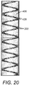
- the helical tracks 300, 300a, 300b, 301a, 301b may be formed by wrapping a metallic strip around the inner housing 408 or the rotatable sleeve 406, as the case may be.
- a metallic strip may have a non-conductive backing to support the metallic layer.
- the non-conductive backing may have an adhesive on the reverse side for securing the strip to the outer surface 440 of the rotatable sleeve 406 or the inner housing 408.
- the helical tracks 300, 300a, 300b, 301a, 301b may alternatively comprise conductive ink printed onto a non-conductive substrate.
- This non-conductive substrate may be the inner housing 408 or rotatable sleeve 406 itself or a secondary substrate which is subsequently attached to the inner housing 408 or rotatable sleeve 406.
- the helical tracks 300, 300a, 300b, 301a, 301b may be formed by wrapping a metallic strip around the inner housing 408 or the rotatable sleeve 406, as the case may alternatively be provided by application of a selective plating technique.
- the processor 202 may store the result in the Flash memory 205.
- the display 210 may be controlled to display the result of the dispensed dose determination.
- the display 210 may display the result of the dispensed dose determination for a predetermined time, for example 60 seconds.
- the dispensed dose history may be retrieved electronically from the Flash memory 205 by a user of the device 100 or by a health care professional.
- the dialled dose may be indicated to the user in any conventional way, for example by use of numerals printed on the encoded member. In some other embodiments, the dialled dose is not determined or indicated to the user. Sensing of the presence or absence of track is performed using a contact and the processor.
- this may involve hardware that compares a voltage signal provided by the contact with a threshold and indicting the presence or absence of track through an output that indicates whether the voltage exceeded or did not exceed respectively the threshold.
- it may involve buffering the signal provided by the contact, for instance using an inverter gate or other buffer, sampling the buffered signal and comparing the sampled signal to a reference. Other ways of sensing the presence or absence of track will be apparent to the skilled person.
Landscapes
- Health & Medical Sciences (AREA)
- Animal Behavior & Ethology (AREA)
- General Health & Medical Sciences (AREA)
- Anesthesiology (AREA)
- Biomedical Technology (AREA)
- Heart & Thoracic Surgery (AREA)
- Hematology (AREA)
- Engineering & Computer Science (AREA)
- Vascular Medicine (AREA)
- Life Sciences & Earth Sciences (AREA)
- Public Health (AREA)
- Veterinary Medicine (AREA)
- Physics & Mathematics (AREA)
- General Physics & Mathematics (AREA)
- Fluid Mechanics (AREA)
- Infusion, Injection, And Reservoir Apparatuses (AREA)
Claims (11)
- Medikamenten-Verabreichungsvorrichtung, umfassend:eine Gehäusekomponente (408), die konzentrisch in einer Hülse (406) angeordnet ist, wobei die Gehäusekomponente Gehäusekomponentengewindemittel (432) umfasst und die Hülse Hülsengewindemittel (436) umfasst, die mit den Gehäusekomponentengewindemitteln derart in Eingriff kommen, dass eine Drehung der Gehäusekomponente in der Hülse verursacht wird, wenn sich die Gehäusekomponente und die Hülsenkomponente bezüglich einander axial bewegen, durch die Kraft einer Eingriffsfläche (710) der Hülsengewindemittel gegen eine Eingriffsfläche der Gehäusekomponentengewindemittel, die Gleiten der Eingriffsfläche der Hülsengewindemittel über die Eingriffsfläche der Gehäusekomponentengewindemittel verursacht,wobei eines der Gehäusekomponente und der Hülse einen ersten Teil und das andere der Gehäusekomponente und der Hülse einen zweiten Teil darstellt, undwobei ein Muster einer Leiterbahn (300) auf den Gewindemitteln des ersten Teils ausgebildet ist und mehrere Kontakte auf dem zweiten Teil ausgebildet sind, um das Leiterbahnmuster zu kontaktieren, wenn sich die Gehäusekomponente in der Hülse dreht.
- Medikamenten-Verabreichungsvorrichtung nach Anspruch 1, wobei das Leiterbahnmuster das Folgende umfasst:einen kontinuierlichen Abschnitt (306), der sich spiralförmig auf dem ersten Teil erstreckt und der nicht in direktem Kontakt mit den mehreren Kontakten ist, die auf dem zweiten Teil ausgebildet sind, wenn sich die Gehäusekomponente in der Hülse dreht, undeinen diskontinuierlichen Abschnitt (302, 304), der sich spiralförmig auf dem ersten Teil erstreckt, der mit dem kontinuierlichen Abschnitt des Leiterbahnmusters verbunden ist und der in direktem Kontakt mit den mehreren Kontakten ist, die auf dem zweiten Teil ausgebildet sind, wenn sich die Gehäusekomponente in der Hülse dreht.
- Medikamenten-Verabreichungsvorrichtung nach Anspruch 2, wobei der diskontinuierliche Abschnitt des Leiterbahnmusters auf der Eingriffsfläche der Gewindekomponente des ersten Teils vorgesehen ist und wobei der kontinuierliche Abschnitt des Leiterbahnmusters auf einer Nicht-Eingriffsfläche der Gewindekomponente des ersten Teils vorgesehen ist.
- Medikamenten-Verabreichungsvorrichtung nach einem der vorhergehenden Ansprüche, wobei erste und zweite Leiterbahnmuster auf den Gewindemitteln des ersten Teils ausgebildet sind und mehrere Kontakte (212) auf dem zweiten Teil ausgebildet sind, um die ersten und zweiten Leiterbahnmuster zu kontaktieren, wenn sich die Gehäusekomponente in der Hülse dreht.
- Medikamenten-Verabreichungsvorrichtung nach einem der Ansprüche 1 bis 3, wobei das Leiterbahnmuster aus einem einzelnen Leiterbahnmuster besteht.
- Medikamenten-Verabreichungsvorrichtung nach einem der vorhergehenden Ansprüche, wobei die Hülsengewindemittel Teile von ersten und zweiten von unterschiedlichen Anfangsgewinden bilden und wobei die Hülsengewindemittel und die Gehäusekomponentenmittel Teile von ersten und zweiten von unterschiedlichen Anfangsgewinden bilden.
- Medikamenten-Verabreichungsvorrichtung nach einem der vorhergehenden Ansprüche, wobei die Gewindemittel jedes Gewindes des ersten Teils ein Leiterbahnmuster aufweisen und wobei die Gewindemittel jedes Gewindes des zweiten Teils jeweilige mehrere Kontakte aufweisen.
- Medikamenten-Verabreichungsvorrichtung nach einem der vorhergehenden Ansprüche, wobei die Gehäusekomponente den ersten Teil darstellt und wobei die Hülse den zweiten Teil darstellt.
- Medikamenten-Verabreichungsvorrichtung nach einem der Ansprüche 1 bis 7, wobei die Hülse den ersten Teil darstellt und wobei die Gehäusekomponente den zweiten Teil darstellt.
- Medikamenten-Verabreichungsvorrichtung nach einem der vorhergehenden Ansprüche, wobei jeder der mehreren Kontakte gefedert ist, um so eine Vorspannkraft zwischen den Hülsengewindemitteln und den Gehäusekomponentengewindemitteln bereitzustellen.
- Medikamenten-Verabreichungsvorrichtung nach einem der vorhergehenden Ansprüche, ferner umfassend einen Prozessor (202), der zum Empfangen und Auswerten von Signalen von jedem der elektrischen Kontakte ausgelegt ist, um die Position des zylindrischen Elements bezüglich des Gehäuses zu bestimmen.
Priority Applications (1)
| Application Number | Priority Date | Filing Date | Title |
|---|---|---|---|
| EP14700373.5A EP2945669B1 (de) | 2013-01-15 | 2014-01-13 | Stiftartiger arzneimittelinjektor mit reibungsarmer dosismessvorrichtung auf einem gewinde |
Applications Claiming Priority (3)
| Application Number | Priority Date | Filing Date | Title |
|---|---|---|---|
| EP13151367 | 2013-01-15 | ||
| PCT/EP2014/050465 WO2014111338A1 (en) | 2013-01-15 | 2014-01-13 | Pen type drug injection device with low friction dose encoder mechanism on thread |
| EP14700373.5A EP2945669B1 (de) | 2013-01-15 | 2014-01-13 | Stiftartiger arzneimittelinjektor mit reibungsarmer dosismessvorrichtung auf einem gewinde |
Publications (2)
| Publication Number | Publication Date |
|---|---|
| EP2945669A1 EP2945669A1 (de) | 2015-11-25 |
| EP2945669B1 true EP2945669B1 (de) | 2018-03-14 |
Family
ID=47520851
Family Applications (1)
| Application Number | Title | Priority Date | Filing Date |
|---|---|---|---|
| EP14700373.5A Active EP2945669B1 (de) | 2013-01-15 | 2014-01-13 | Stiftartiger arzneimittelinjektor mit reibungsarmer dosismessvorrichtung auf einem gewinde |
Country Status (8)
| Country | Link |
|---|---|
| US (1) | US10112017B2 (de) |
| EP (1) | EP2945669B1 (de) |
| JP (1) | JP6373869B2 (de) |
| CN (1) | CN104918647B (de) |
| DK (1) | DK2945669T3 (de) |
| HK (1) | HK1211513A1 (de) |
| TR (1) | TR201808294T4 (de) |
| WO (1) | WO2014111338A1 (de) |
Families Citing this family (8)
| Publication number | Priority date | Publication date | Assignee | Title |
|---|---|---|---|---|
| EP3045186A1 (de) | 2015-01-16 | 2016-07-20 | Sanofi-Aventis Deutschland GmbH | Sensor zur Verwendung mit einer Arzneimittelverabreichungsvorrichtung |
| CN105999481A (zh) * | 2016-06-16 | 2016-10-12 | 广东东阳光药业有限公司 | 一种注射器用刻度数据采集结构及注射器 |
| AU2017297299C1 (en) | 2016-07-15 | 2020-06-11 | Eli Lilly And Company | Dose detection module for a medication delivery device |
| CN108066849A (zh) * | 2016-11-15 | 2018-05-25 | 广东东阳光药业有限公司 | 一种自动采集刻度数据的注射器 |
| US11672914B2 (en) | 2017-12-21 | 2023-06-13 | Sanofi | RFID dose tracking mechanism for injection devices |
| EP3855136B1 (de) | 2018-04-05 | 2024-02-28 | Kamstrup A/S | Kompakter ultraschalldurchflussmesser |
| CN113056299B (zh) * | 2018-11-23 | 2023-11-03 | 赛诺菲 | 用于药物递送装置的电子墨水标签 |
| CN114746136A (zh) * | 2019-11-21 | 2022-07-12 | 赛诺菲 | 药剂递送装置和剂量测量系统 |
Family Cites Families (41)
| Publication number | Priority date | Publication date | Assignee | Title |
|---|---|---|---|---|
| US533575A (en) | 1895-02-05 | wilkens | ||
| US5226895A (en) | 1989-06-05 | 1993-07-13 | Eli Lilly And Company | Multiple dose injection pen |
| GB9007113D0 (en) | 1990-03-29 | 1990-05-30 | Sams Bernard | Dispensing device |
| DE59202070D1 (de) | 1991-07-24 | 1995-06-08 | Medico Dev Investment Co | Injektor. |
| DK175491D0 (da) | 1991-10-18 | 1991-10-18 | Novo Nordisk As | Apparat |
| US5279585A (en) | 1992-02-04 | 1994-01-18 | Becton, Dickinson And Company | Medication delivery pen having improved dose delivery features |
| US5320609A (en) | 1992-12-07 | 1994-06-14 | Habley Medical Technology Corporation | Automatic pharmaceutical dispensing syringe |
| US5383865A (en) | 1993-03-15 | 1995-01-24 | Eli Lilly And Company | Medication dispensing device |
| ZA941881B (en) | 1993-04-02 | 1995-09-18 | Lilly Co Eli | Manifold medication injection apparatus and method |
| US5582598A (en) | 1994-09-19 | 1996-12-10 | Becton Dickinson And Company | Medication delivery pen with variable increment dose scale |
| JP3568959B2 (ja) | 1995-03-07 | 2004-09-22 | イーライ・リリー・アンド・カンパニー | 再利用可能な投薬装置 |
| US5688251A (en) | 1995-09-19 | 1997-11-18 | Becton Dickinson And Company | Cartridge loading and priming mechanism for a pen injector |
| US5674204A (en) | 1995-09-19 | 1997-10-07 | Becton Dickinson And Company | Medication delivery pen cap actuated dose delivery clutch |
| DE19730999C1 (de) | 1997-07-18 | 1998-12-10 | Disetronic Licensing Ag | Dosierknopfsicherung an einer Vorrichtung zur dosierten Verabreichung eines injizierbaren Produkts |
| US5957896A (en) | 1997-08-11 | 1999-09-28 | Becton, Dickinson And Company | Medication delivery pen |
| PT1003581E (pt) | 1998-01-30 | 2001-04-30 | Novo Nordisk As | Seringa de injeccao |
| US6221053B1 (en) | 1998-02-20 | 2001-04-24 | Becton, Dickinson And Company | Multi-featured medication delivery pen |
| US5961495A (en) | 1998-02-20 | 1999-10-05 | Becton, Dickinson And Company | Medication delivery pen having a priming mechanism |
| US6248095B1 (en) | 1998-02-23 | 2001-06-19 | Becton, Dickinson And Company | Low-cost medication delivery pen |
| DE60026147T2 (de) | 1999-08-05 | 2006-11-23 | Becton, Dickinson And Co. | Stiftförmige medikamentenabgabevorrichtung |
| US6585698B1 (en) * | 1999-11-01 | 2003-07-01 | Becton, Dickinson & Company | Electronic medical delivery pen having a multifunction actuator |
| GB0007071D0 (en) | 2000-03-24 | 2000-05-17 | Sams Bernard | One-way clutch mechanisms and injector devices |
| US6663602B2 (en) | 2000-06-16 | 2003-12-16 | Novo Nordisk A/S | Injection device |
| US6899699B2 (en) | 2001-01-05 | 2005-05-31 | Novo Nordisk A/S | Automatic injection device with reset feature |
| EP2258424B1 (de) | 2001-05-16 | 2013-01-30 | Eli Lilly and Company | Spritzvorrichtung |
| GB0304823D0 (en) | 2003-03-03 | 2003-04-09 | Dca Internat Ltd | Improvements in and relating to a pen-type injector |
| DE102004063645A1 (de) | 2004-12-31 | 2006-07-20 | Tecpharma Licensing Ag | Vorrichtung zur dosierten Verabreichung eines fluiden Produkts mit Entkopplung für einen Behältniswechsel |
| US8197449B2 (en) * | 2005-05-10 | 2012-06-12 | Novo Nordisk A/S | Injection device comprising an optical sensor |
| DE102005023824A1 (de) * | 2005-05-24 | 2006-12-07 | Tecpharma Licensing Ag | Dosiervorrichtung für eine Injektionsvorrichtung |
| BRPI0616109A2 (pt) * | 2005-09-22 | 2011-06-07 | Novo Nordisk As | dispositivo e método para determinação de posição absoluta sem contato |
| WO2007116090A1 (en) * | 2006-04-12 | 2007-10-18 | Novo Nordisk A/S | Absolute position determination of movably mounted member in medication delivery device |
| CN101489607B (zh) | 2006-07-15 | 2012-09-05 | 诺沃-诺迪斯克有限公司 | 具有可旋转编码元件的医疗输送系统 |
| CN101557850A (zh) * | 2006-11-17 | 2009-10-14 | 诺沃-诺迪斯克有限公司 | 包括剂量给药组件与药剂容器之间的编码机构的医用输送系统 |
| WO2008113772A1 (en) * | 2007-03-21 | 2008-09-25 | Novo Nordisk A/S | A medical delivery system having container recognition and container for use with the medical delivery system |
| PL2229201T3 (pl) | 2007-12-31 | 2012-10-31 | Novo Nordisk As | Elektronicznie monitorowane urządzenie do wstrzykiwania |
| US8647309B2 (en) | 2008-05-02 | 2014-02-11 | Sanofi-Aventis Deutschland Gmbh | Medication delivery device |
| ES2673294T3 (es) | 2008-11-06 | 2018-06-21 | Novo Nordisk A/S | Dispositivo de administración de fármacos asistido electrónicamente |
| US9345840B2 (en) * | 2009-06-01 | 2016-05-24 | Sanofi-Aventis Deutschland Gmbh | Drug delivery dose setting mechanism with variable maximum dose |
| KR101939267B1 (ko) * | 2010-07-21 | 2019-01-16 | 삼성전자주식회사 | 주사기의 주사량 측정 장치 및 방법 |
| CN103702699B (zh) | 2011-07-07 | 2016-08-17 | 诺沃—诺迪斯克有限公司 | 具有附加的剂量捕获和显示模块的药物输送注射笔 |
| US9192728B2 (en) * | 2011-07-15 | 2015-11-24 | Sanofi-Aventis Deutschland Gmbh | Drug delivery device |
-
2014
- 2014-01-13 WO PCT/EP2014/050465 patent/WO2014111338A1/en active Application Filing
- 2014-01-13 US US14/759,908 patent/US10112017B2/en active Active
- 2014-01-13 DK DK14700373.5T patent/DK2945669T3/en active
- 2014-01-13 JP JP2015552071A patent/JP6373869B2/ja active Active
- 2014-01-13 CN CN201480004479.4A patent/CN104918647B/zh active Active
- 2014-01-13 EP EP14700373.5A patent/EP2945669B1/de active Active
- 2014-01-13 TR TR2018/08294T patent/TR201808294T4/tr unknown
-
2015
- 2015-12-15 HK HK15112324.5A patent/HK1211513A1/xx unknown
Also Published As
| Publication number | Publication date |
|---|---|
| WO2014111338A1 (en) | 2014-07-24 |
| HK1211513A1 (en) | 2016-05-27 |
| TR201808294T4 (tr) | 2018-07-23 |
| CN104918647B (zh) | 2018-04-13 |
| JP6373869B2 (ja) | 2018-08-15 |
| CN104918647A (zh) | 2015-09-16 |
| EP2945669A1 (de) | 2015-11-25 |
| US20150352289A1 (en) | 2015-12-10 |
| US10112017B2 (en) | 2018-10-30 |
| JP2016506764A (ja) | 2016-03-07 |
| DK2945669T3 (en) | 2018-07-09 |
Similar Documents
| Publication | Publication Date | Title |
|---|---|---|
| EP2945669B1 (de) | Stiftartiger arzneimittelinjektor mit reibungsarmer dosismessvorrichtung auf einem gewinde | |
| EP2945671B1 (de) | Stiftartiger arzneimittelinjektor mit reibungsreduzierender dosismessvorrichtung | |
| US11484658B2 (en) | Pen type drug injection device with absolute angular dose encoder mechanism | |
| EP2945670B1 (de) | Stiftartiger arzneimittelinjektor mit dosismessvorrichtung und schalter zum bestimmen von dosiseinstellungs- und -abgabemodus | |
| JP6733029B2 (ja) | 薬物吐出装置のための投与量検出モジュール | |
| JP7163443B2 (ja) | 感知システムを有する薬剤送達デバイス | |
| EP2945673B1 (de) | Dekodiersystem | |
| EP2945665B1 (de) | Stiftartiger arzneimittelinjektor mit optischem dosisdecodiersystem sowie sensor zur unterscheidung von dosiseinstell- und dosisabgabemodus |
Legal Events
| Date | Code | Title | Description |
|---|---|---|---|
| PUAI | Public reference made under article 153(3) epc to a published international application that has entered the european phase |
Free format text: ORIGINAL CODE: 0009012 |
|
| 17P | Request for examination filed |
Effective date: 20150817 |
|
| AK | Designated contracting states |
Kind code of ref document: A1 Designated state(s): AL AT BE BG CH CY CZ DE DK EE ES FI FR GB GR HR HU IE IS IT LI LT LU LV MC MK MT NL NO PL PT RO RS SE SI SK SM TR |
|
| AX | Request for extension of the european patent |
Extension state: BA ME |
|
| DAX | Request for extension of the european patent (deleted) | ||
| REG | Reference to a national code |
Ref country code: HK Ref legal event code: DE Ref document number: 1211513 Country of ref document: HK |
|
| GRAP | Despatch of communication of intention to grant a patent |
Free format text: ORIGINAL CODE: EPIDOSNIGR1 |
|
| STAA | Information on the status of an ep patent application or granted ep patent |
Free format text: STATUS: GRANT OF PATENT IS INTENDED |
|
| RIC1 | Information provided on ipc code assigned before grant |
Ipc: G01D 5/165 20060101ALI20170829BHEP Ipc: A61M 5/31 20060101ALI20170829BHEP Ipc: A61M 5/315 20060101AFI20170829BHEP Ipc: G01F 11/02 20060101ALI20170829BHEP Ipc: G01D 5/00 20060101ALI20170829BHEP |
|
| INTG | Intention to grant announced |
Effective date: 20171004 |
|
| GRAS | Grant fee paid |
Free format text: ORIGINAL CODE: EPIDOSNIGR3 |
|
| GRAA | (expected) grant |
Free format text: ORIGINAL CODE: 0009210 |
|
| STAA | Information on the status of an ep patent application or granted ep patent |
Free format text: STATUS: THE PATENT HAS BEEN GRANTED |
|
| AK | Designated contracting states |
Kind code of ref document: B1 Designated state(s): AL AT BE BG CH CY CZ DE DK EE ES FI FR GB GR HR HU IE IS IT LI LT LU LV MC MK MT NL NO PL PT RO RS SE SI SK SM TR |
|
| REG | Reference to a national code |
Ref country code: GB Ref legal event code: FG4D |
|
| REG | Reference to a national code |
Ref country code: CH Ref legal event code: EP Ref country code: AT Ref legal event code: REF Ref document number: 978243 Country of ref document: AT Kind code of ref document: T Effective date: 20180315 |
|
| REG | Reference to a national code |
Ref country code: IE Ref legal event code: FG4D |
|
| REG | Reference to a national code |
Ref country code: DE Ref legal event code: R096 Ref document number: 602014022287 Country of ref document: DE |
|
| REG | Reference to a national code |
Ref country code: DK Ref legal event code: T3 Effective date: 20180704 |
|
| REG | Reference to a national code |
Ref country code: NL Ref legal event code: MP Effective date: 20180314 |
|
| REG | Reference to a national code |
Ref country code: LT Ref legal event code: MG4D |
|
| PG25 | Lapsed in a contracting state [announced via postgrant information from national office to epo] |
Ref country code: NO Free format text: LAPSE BECAUSE OF FAILURE TO SUBMIT A TRANSLATION OF THE DESCRIPTION OR TO PAY THE FEE WITHIN THE PRESCRIBED TIME-LIMIT Effective date: 20180614 Ref country code: HR Free format text: LAPSE BECAUSE OF FAILURE TO SUBMIT A TRANSLATION OF THE DESCRIPTION OR TO PAY THE FEE WITHIN THE PRESCRIBED TIME-LIMIT Effective date: 20180314 Ref country code: LT Free format text: LAPSE BECAUSE OF FAILURE TO SUBMIT A TRANSLATION OF THE DESCRIPTION OR TO PAY THE FEE WITHIN THE PRESCRIBED TIME-LIMIT Effective date: 20180314 Ref country code: CY Free format text: LAPSE BECAUSE OF FAILURE TO SUBMIT A TRANSLATION OF THE DESCRIPTION OR TO PAY THE FEE WITHIN THE PRESCRIBED TIME-LIMIT Effective date: 20180314 Ref country code: FI Free format text: LAPSE BECAUSE OF FAILURE TO SUBMIT A TRANSLATION OF THE DESCRIPTION OR TO PAY THE FEE WITHIN THE PRESCRIBED TIME-LIMIT Effective date: 20180314 |
|
| REG | Reference to a national code |
Ref country code: AT Ref legal event code: MK05 Ref document number: 978243 Country of ref document: AT Kind code of ref document: T Effective date: 20180314 |
|
| PG25 | Lapsed in a contracting state [announced via postgrant information from national office to epo] |
Ref country code: BG Free format text: LAPSE BECAUSE OF FAILURE TO SUBMIT A TRANSLATION OF THE DESCRIPTION OR TO PAY THE FEE WITHIN THE PRESCRIBED TIME-LIMIT Effective date: 20180614 Ref country code: GR Free format text: LAPSE BECAUSE OF FAILURE TO SUBMIT A TRANSLATION OF THE DESCRIPTION OR TO PAY THE FEE WITHIN THE PRESCRIBED TIME-LIMIT Effective date: 20180615 Ref country code: SE Free format text: LAPSE BECAUSE OF FAILURE TO SUBMIT A TRANSLATION OF THE DESCRIPTION OR TO PAY THE FEE WITHIN THE PRESCRIBED TIME-LIMIT Effective date: 20180314 Ref country code: LV Free format text: LAPSE BECAUSE OF FAILURE TO SUBMIT A TRANSLATION OF THE DESCRIPTION OR TO PAY THE FEE WITHIN THE PRESCRIBED TIME-LIMIT Effective date: 20180314 Ref country code: RS Free format text: LAPSE BECAUSE OF FAILURE TO SUBMIT A TRANSLATION OF THE DESCRIPTION OR TO PAY THE FEE WITHIN THE PRESCRIBED TIME-LIMIT Effective date: 20180314 |
|
| PG25 | Lapsed in a contracting state [announced via postgrant information from national office to epo] |
Ref country code: PL Free format text: LAPSE BECAUSE OF FAILURE TO SUBMIT A TRANSLATION OF THE DESCRIPTION OR TO PAY THE FEE WITHIN THE PRESCRIBED TIME-LIMIT Effective date: 20180314 Ref country code: EE Free format text: LAPSE BECAUSE OF FAILURE TO SUBMIT A TRANSLATION OF THE DESCRIPTION OR TO PAY THE FEE WITHIN THE PRESCRIBED TIME-LIMIT Effective date: 20180314 Ref country code: AL Free format text: LAPSE BECAUSE OF FAILURE TO SUBMIT A TRANSLATION OF THE DESCRIPTION OR TO PAY THE FEE WITHIN THE PRESCRIBED TIME-LIMIT Effective date: 20180314 Ref country code: NL Free format text: LAPSE BECAUSE OF FAILURE TO SUBMIT A TRANSLATION OF THE DESCRIPTION OR TO PAY THE FEE WITHIN THE PRESCRIBED TIME-LIMIT Effective date: 20180314 Ref country code: RO Free format text: LAPSE BECAUSE OF FAILURE TO SUBMIT A TRANSLATION OF THE DESCRIPTION OR TO PAY THE FEE WITHIN THE PRESCRIBED TIME-LIMIT Effective date: 20180314 Ref country code: ES Free format text: LAPSE BECAUSE OF FAILURE TO SUBMIT A TRANSLATION OF THE DESCRIPTION OR TO PAY THE FEE WITHIN THE PRESCRIBED TIME-LIMIT Effective date: 20180314 |
|
| PG25 | Lapsed in a contracting state [announced via postgrant information from national office to epo] |
Ref country code: AT Free format text: LAPSE BECAUSE OF FAILURE TO SUBMIT A TRANSLATION OF THE DESCRIPTION OR TO PAY THE FEE WITHIN THE PRESCRIBED TIME-LIMIT Effective date: 20180314 Ref country code: CZ Free format text: LAPSE BECAUSE OF FAILURE TO SUBMIT A TRANSLATION OF THE DESCRIPTION OR TO PAY THE FEE WITHIN THE PRESCRIBED TIME-LIMIT Effective date: 20180314 Ref country code: SK Free format text: LAPSE BECAUSE OF FAILURE TO SUBMIT A TRANSLATION OF THE DESCRIPTION OR TO PAY THE FEE WITHIN THE PRESCRIBED TIME-LIMIT Effective date: 20180314 Ref country code: SM Free format text: LAPSE BECAUSE OF FAILURE TO SUBMIT A TRANSLATION OF THE DESCRIPTION OR TO PAY THE FEE WITHIN THE PRESCRIBED TIME-LIMIT Effective date: 20180314 |
|
| REG | Reference to a national code |
Ref country code: DE Ref legal event code: R097 Ref document number: 602014022287 Country of ref document: DE |
|
| PG25 | Lapsed in a contracting state [announced via postgrant information from national office to epo] |
Ref country code: PT Free format text: LAPSE BECAUSE OF FAILURE TO SUBMIT A TRANSLATION OF THE DESCRIPTION OR TO PAY THE FEE WITHIN THE PRESCRIBED TIME-LIMIT Effective date: 20180716 |
|
| PLBE | No opposition filed within time limit |
Free format text: ORIGINAL CODE: 0009261 |
|
| STAA | Information on the status of an ep patent application or granted ep patent |
Free format text: STATUS: NO OPPOSITION FILED WITHIN TIME LIMIT |
|
| 26N | No opposition filed |
Effective date: 20181217 |
|
| PG25 | Lapsed in a contracting state [announced via postgrant information from national office to epo] |
Ref country code: IT Free format text: LAPSE BECAUSE OF FAILURE TO SUBMIT A TRANSLATION OF THE DESCRIPTION OR TO PAY THE FEE WITHIN THE PRESCRIBED TIME-LIMIT Effective date: 20180314 Ref country code: SI Free format text: LAPSE BECAUSE OF FAILURE TO SUBMIT A TRANSLATION OF THE DESCRIPTION OR TO PAY THE FEE WITHIN THE PRESCRIBED TIME-LIMIT Effective date: 20180314 |
|
| PGFP | Annual fee paid to national office [announced via postgrant information from national office to epo] |
Ref country code: AT Payment date: 20190219 Year of fee payment: 13 |
|
| PG25 | Lapsed in a contracting state [announced via postgrant information from national office to epo] |
Ref country code: MC Free format text: LAPSE BECAUSE OF FAILURE TO SUBMIT A TRANSLATION OF THE DESCRIPTION OR TO PAY THE FEE WITHIN THE PRESCRIBED TIME-LIMIT Effective date: 20180314 |
|
| PG25 | Lapsed in a contracting state [announced via postgrant information from national office to epo] |
Ref country code: LU Free format text: LAPSE BECAUSE OF NON-PAYMENT OF DUE FEES Effective date: 20190113 |
|
| REG | Reference to a national code |
Ref country code: BE Ref legal event code: MM Effective date: 20190131 |
|
| REG | Reference to a national code |
Ref country code: IE Ref legal event code: MM4A |
|
| PG25 | Lapsed in a contracting state [announced via postgrant information from national office to epo] |
Ref country code: BE Free format text: LAPSE BECAUSE OF NON-PAYMENT OF DUE FEES Effective date: 20190131 |
|
| PG25 | Lapsed in a contracting state [announced via postgrant information from national office to epo] |
Ref country code: IE Free format text: LAPSE BECAUSE OF NON-PAYMENT OF DUE FEES Effective date: 20190113 |
|
| PG25 | Lapsed in a contracting state [announced via postgrant information from national office to epo] |
Ref country code: MT Free format text: LAPSE BECAUSE OF NON-PAYMENT OF DUE FEES Effective date: 20190113 |
|
| PG25 | Lapsed in a contracting state [announced via postgrant information from national office to epo] |
Ref country code: IS Free format text: LAPSE BECAUSE OF FAILURE TO SUBMIT A TRANSLATION OF THE DESCRIPTION OR TO PAY THE FEE WITHIN THE PRESCRIBED TIME-LIMIT Effective date: 20180714 |
|
| PG25 | Lapsed in a contracting state [announced via postgrant information from national office to epo] |
Ref country code: HU Free format text: LAPSE BECAUSE OF FAILURE TO SUBMIT A TRANSLATION OF THE DESCRIPTION OR TO PAY THE FEE WITHIN THE PRESCRIBED TIME-LIMIT; INVALID AB INITIO Effective date: 20140113 |
|
| PG25 | Lapsed in a contracting state [announced via postgrant information from national office to epo] |
Ref country code: TR Free format text: LAPSE BECAUSE OF NON-PAYMENT OF DUE FEES Effective date: 20200113 Ref country code: MK Free format text: LAPSE BECAUSE OF FAILURE TO SUBMIT A TRANSLATION OF THE DESCRIPTION OR TO PAY THE FEE WITHIN THE PRESCRIBED TIME-LIMIT Effective date: 20180314 |
|
| PGFP | Annual fee paid to national office [announced via postgrant information from national office to epo] |
Ref country code: GB Payment date: 20231130 Year of fee payment: 11 |
|
| PGFP | Annual fee paid to national office [announced via postgrant information from national office to epo] |
Ref country code: FR Payment date: 20231212 Year of fee payment: 11 |
|
| PGFP | Annual fee paid to national office [announced via postgrant information from national office to epo] |
Ref country code: DE Payment date: 20231205 Year of fee payment: 11 Ref country code: CH Payment date: 20240201 Year of fee payment: 11 |
|
| PGFP | Annual fee paid to national office [announced via postgrant information from national office to epo] |
Ref country code: DK Payment date: 20240111 Year of fee payment: 11 |