EP2945428B1 - Radiokommunikationssystem und kommunikationssteuerungsverfahren - Google Patents
Radiokommunikationssystem und kommunikationssteuerungsverfahren Download PDFInfo
- Publication number
- EP2945428B1 EP2945428B1 EP13870740.1A EP13870740A EP2945428B1 EP 2945428 B1 EP2945428 B1 EP 2945428B1 EP 13870740 A EP13870740 A EP 13870740A EP 2945428 B1 EP2945428 B1 EP 2945428B1
- Authority
- EP
- European Patent Office
- Prior art keywords
- base station
- cell
- transmission timing
- user device
- synchronization
- Prior art date
- Legal status (The legal status is an assumption and is not a legal conclusion. Google has not performed a legal analysis and makes no representation as to the accuracy of the status listed.)
- Active
Links
- 238000004891 communication Methods 0.000 title claims description 101
- 238000000034 method Methods 0.000 title claims description 11
- 230000005540 biological transmission Effects 0.000 claims description 170
- 230000001360 synchronised effect Effects 0.000 claims description 31
- 230000003111 delayed effect Effects 0.000 claims description 11
- 230000007423 decrease Effects 0.000 claims description 2
- 238000010586 diagram Methods 0.000 description 36
- 238000001514 detection method Methods 0.000 description 34
- 230000004048 modification Effects 0.000 description 16
- 238000012986 modification Methods 0.000 description 16
- 239000013256 coordination polymer Substances 0.000 description 11
- 230000000694 effects Effects 0.000 description 7
- 238000004590 computer program Methods 0.000 description 6
- 230000005859 cell recognition Effects 0.000 description 5
- 230000008054 signal transmission Effects 0.000 description 4
- CIWBSHSKHKDKBQ-JLAZNSOCSA-N Ascorbic acid Chemical compound OC[C@H](O)[C@H]1OC(=O)C(O)=C1O CIWBSHSKHKDKBQ-JLAZNSOCSA-N 0.000 description 3
- 125000004122 cyclic group Chemical group 0.000 description 3
- 239000013307 optical fiber Substances 0.000 description 3
- 108010076504 Protein Sorting Signals Proteins 0.000 description 2
- 238000004364 calculation method Methods 0.000 description 2
- 239000000969 carrier Substances 0.000 description 2
- 230000012447 hatching Effects 0.000 description 2
- 230000007774 longterm Effects 0.000 description 2
- 230000001419 dependent effect Effects 0.000 description 1
- 238000005516 engineering process Methods 0.000 description 1
Images


Classifications
-
- H—ELECTRICITY
- H04—ELECTRIC COMMUNICATION TECHNIQUE
- H04W—WIRELESS COMMUNICATION NETWORKS
- H04W56/00—Synchronisation arrangements
- H04W56/001—Synchronization between nodes
- H04W56/0015—Synchronization between nodes one node acting as a reference for the others
-
- H—ELECTRICITY
- H04—ELECTRIC COMMUNICATION TECHNIQUE
- H04W—WIRELESS COMMUNICATION NETWORKS
- H04W48/00—Access restriction; Network selection; Access point selection
- H04W48/08—Access restriction or access information delivery, e.g. discovery data delivery
- H04W48/10—Access restriction or access information delivery, e.g. discovery data delivery using broadcasted information
-
- H—ELECTRICITY
- H04—ELECTRIC COMMUNICATION TECHNIQUE
- H04W—WIRELESS COMMUNICATION NETWORKS
- H04W48/00—Access restriction; Network selection; Access point selection
- H04W48/16—Discovering, processing access restriction or access information
Definitions
- the present invention relates to radio communication systems and to communication control methods.
- a user device performs cell searching to establish synchronization with a macro base station so as to perform radio communication.
- LTE/SAE Long Term Evolution/System Architecture Evolution
- a user device performs cell searching to establish synchronization with a macro base station so as to perform radio communication.
- the user device by calculating correlations between a synchronization signal transmitted by the macro base station and a replica signal stored in the user device, detects a transmission timing of the synchronization signal and a physical cell identity (PCI) so as to recognize (identify) the macro base station.
- PCI physical cell identity
- Patent Document 1 Japanese Patent Application Laid-Open Publication No. 2009-188612 US 2009/316659 A1 relates to multi-component carrier cells and a method of generating and informing component carrier cell ID information.
- the method associates different cell IDs on different carrier frequencies, such as cell IDs of legacy LTE or HSPA cells, with a multi-component carrier cell ID (i.e., component carriers belonging to the same multi-carrier cell).
- Legacy cells use different carrier frequencies f1, f2, and a multi-component carrier cell comprises two such cells placed at the same site. There is a cell ID a on frequency f1 and a cell ID b on frequency f2.
- the cell a In order for the multi-carrier UE to find cell ID b at frequency f2 when doing cell search on carrier frequency f1, the cell a broadcasts on frequency f1 extended synchronization information that includes information about cell ID b on carrier frequency f2.
- the cell b broadcasts on frequency f2 extended synchronization information that includes information about cell ID a on carrier frequency f1 in order for the UE to find cell ID a at frequency f1 when doing cell search on carrier frequency f2.
- the UE determines that it is in a multi-component carrier cell, with cell ID a on frequency f1 and cell ID b on frequency f2, by detecting the extended synchronization information. The UE can then carry out an improved cell search procedure that uses the extended synchronization information.
- the radio communication system above is assumed to include a new type of base station (hereinafter referred to as a small base station) that performs radio communication using a frequency band (e.g., 3.5 GHz band) that is different from a frequency band that the macro base station uses (e.g., 2 GHz band) to perform radio communication.
- a frequency band e.g., 3.5 GHz band
- a frequency band that the macro base station uses e.g., 2 GHz band
- a radio communication system includes: base stations that include a first base station and a second base station, the first base station performing radio communication using a first frequency band and being identified by a first cell identity, the second base station performing radio communication with each of the base stations.
- the first base station includes: a first transmitting unit that transmits, at a first transmission timing, a first synchronization signal that indicates the first cell identity, which identifies the first base station.
- the second base station includes: a second transmitting unit that transmits an identification signal that indicates the second cell identity, which identifies the second base station.
- the user device includes: a cell searcher that detects the first transmission timing based on the first synchronization signal received from the first base station and performs timing-search processing that establishes synchronization with the first base station.
- the first base station further includes: an information notifying unit that notifies the user device of synchronization state information related to a synchronization state between the first base station and the second base station and of frequency information related to an identification signal frequency that the second base station uses to transmit the identification signal, the identification signal frequency being included in the second frequency band.
- the cell searcher of the user device based on the synchronization state information from the first base station, performs identifying processing on the identification signal frequency indicated by the frequency information to identify the second cell identity indicated by the identification signal.
- the first base station and the second base station are synchronized with each other to perform radio communication.
- the second transmitting unit of the second base station transmits a second synchronization signal at a second transmission timing.
- the synchronization state information which is notified by the information notifying unit of the first base station, indicates whether the first base station and the second base station are synchronized.
- the cell searcher of the user device identifies the second transmission timing by performing timing-search processing for the second base station over a predetermined period that includes the first transmission timing and performs identifying processing based on the second transmission timing to identify the second cell identity indicated by the identification signal.
- the second transmitting unit of the second base station further transmits a cell-specific signal that includes the identification signal and is different from the second synchronization signal, and the cell searcher of the user device performs identifying processing to identify the second cell identity indicated by the identification signal included in the cell-specific signal.
- the information notifying unit of the first base station transmits, to the user device UE, configuration information that indicates a transmission timing of the cell-specific signal and information on a CP length in radio communication performed by the second base station.
- the cell searcher of the user device further using the configuration information and the information on the CP length, performs identifying processing to identify the second cell identity indicated by the identification signal included in the cell-specific signal.
- the second transmitting unit of the second base station transmits a second synchronization signal that includes the identification signal at the second transmission timing, the second transmission timing being a timing that is delayed from the first transmission timing at the first base station by a length of time that corresponds to a transmission offset value.
- the synchronization state information which is notified by the information notifying unit of the first base station, indicates the transmission offset value for the first transmission timing at the first base station.
- the cell searcher of the user device without performing timing-search processing for the second base station, performs identifying processing, based on the first transmission timing and the transmission offset value indicated by the synchronization state information, to identify the second cell identity indicated by the identification signal.
- the second transmitting unit of the second base station transmits a second synchronization signal that includes the identification signal at the second transmission timing, the second transmission timing being a timing that is delayed from the first transmission timing at the first base station by a length of time that corresponds to a transmission offset value.
- the synchronization state information which is notified by the information notifying unit of the first base station, indicates the transmission offset value for the first transmission timing at the first base station.
- the cell searcher of the user device identifies the second transmission timing by performing timing-search processing for the second base station over a predetermined period that includes a transmission timing that is delayed from the first transmission timing by the length of time that corresponds to the transmission offset value indicated by the synchronization state information and performs identifying processing based on the second transmission timing to identify the second cell identity indicated by the identification signal.
- the second base station further includes: a received power measuring unit that measures received power of radio signals received from the first base station; and an offset value setter that sets a transmission offset value so that the transmission offset value increases as the received power measured by the received power measuring unit decreases.
- the second transmitting unit of the second base station transmits a second synchronization signal that includes the identification signal at the second transmission timing, the second transmission timing being a timing that is advanced from the first transmission timing at the first base station by a length of time that corresponds to the transmission offset value.
- the synchronization state information which is notified by the information notifying unit of the first base station, indicates whether the first base station and the second base station are synchronized.
- the cell searcher of the user device When the synchronization state information indicates that the first base station and the second base station are synchronized, the cell searcher of the user device, without performing timing-search processing for the second base station, performs identifying processing based on the first transmission timing to identify the second cell identity indicated by the identification signal.
- the synchronization state information further includes an identity list that indicates second cell identities that correspond to second base stations, and the cell searcher of the user device performs the identifying processing only for the second base stations, which correspond to the second cell identities indicated by the identity list.
- the user device further includes a terminal transmitting unit that transmits a terminal discovery signal that indicates a terminal identifier that identifies the user device, and the second transmitting unit of the second base station transmits the identification signal that has a common signal format with the terminal discovery signal.
- the second transmitting unit of the second base station transmits the identification signal in accordance with an identification signal pattern, the identification signal pattern indicating a configuration of the identification signal in each of the subframes and identifying the second base station.
- a communication control method is used in a radio communication system that includes: base stations that include a first base station and a second base station, the first base station performing radio communication using a first frequency band and being identified by a first cell identity, the second base station performing radio communication using a second frequency band and being identified by a second cell identity; and a user device that performs radio communication with each of the base stations.
- the communication control method includes: in the first base station, transmitting, at a first transmission timing, a first synchronization signal that indicates the first cell identity, which identifies the first base station, in the second base station, transmitting an identification signal that indicates the second cell identity, which identifies the second base station, in the user device, detecting the first transmission timing based on the first synchronization signal received from the first base station and performing timing-search processing that establishes synchronization with the first base station, in the first base station, notifying the user device of synchronization state information related to a synchronization state between the first base station and the second base station and of frequency information related to an identification signal frequency that the second base station uses to transmit the identification signal, the identification signal frequency being included in the second frequency band, and in the user device, using the synchronization state information from the first base station, performing identifying processing on the identification signal frequency indicated by the frequency information to identify the second cell identity included in the identification signal.
- the user device performs identifying processing to identify the second cell identity indicated by the second synchronization signal transmitted by the second base station based on the frequency information and the synchronization state information notified by the first base station. Because timing-search processing for the small base station PhNB is omitted, a processing load on the user device UE to recognize the small base station PhNB is reduced.
- FIG. 1 is a block diagram showing a radio communication system CS according to a first embodiment of the present invention.
- the radio communication system CS includes, as its elements, a macro base station eNB, a small base station PhNB, and a user device UE.
- the radio communication system CS may include, in addition to the elements above, other elements not shown in the figure, for example, a switching center, a serving gateway, and a PDN gateway, etc.
- a network NW includes the above-mentioned elements that the radio communication system CS includes, except for the user device UE.
- Each element in the radio communication system CS performs communication in accordance with a predetermined access technology, e.g., LTE/SAE (Long Term Evolution/System Architecture Evolution) protocol included in the 3GPP (Third Generation Partnership Project) protocols.
- LTE/SAE Long Term Evolution/System Architecture Evolution
- 3GPP Third Generation Partnership Project
- the user device UE is a User Equipment
- the macro base station eNB is an evolved Node B
- the switching center is a Mobile Management Entity
- the serving gateway is a Serving Gateway
- the PDN gateway is a Packet Data Network Gateway.
- the small base station PhNB is a new type of base station that performs radio communication using a frequency band that is different from a frequency band that the macro base station eNB uses (details below).
- the user device UE can perform radio communication with the macro base station eNB and with the small base station PhNB.
- Each of the base stations (eNB and PhNB) is identified by a unique physical cell identity PCI. As described later, each of the base stations (eNB and PhNB) may be identified by a unique identification signal.
- a scheme for radio communication between the user device UE and each of the base stations (eNB and PhNB) can be freely chosen. For example, OFDMA (Orthogonal Frequency Division Multiple Access) may be adopted for downlink, whereas SC-FDMA (Single-Carrier Frequency Division Multiple Access) may be adopted for uplink.
- OFDMA Orthogonal Frequency Division Multiple Access
- SC-FDMA Single-Carrier Frequency Division Multiple Access
- the macro base station eNB and the small base stations PhNB may perform radio communication using different schemes.
- the macro base station eNB and the small base station PhNB are interconnected by a wired interface, such as optical fiber, that can transmit clock signals.
- the macro base station eNB and the small base station PhNB can synchronize with each other according to clock signals.
- Clock signals may be generated at one of the base stations (preferably at the macro base station eNB) to be transmitted to the other base station.
- clock signals to be transmitted to the base stations may be generated at a clock generator (not shown in the figure) that is placed separately from the base stations.
- the macro base station eNB and the small base station PhNB are connected to a core network.
- the core network is a packet communication network that includes the switching center, the serving gateway, and the PDN gateway, etc.
- the small base station PhNB may be connected to the core network by being routed through the macro base station eNB, instead of being connected directly to the core network.
- FIG. 2 shows an example of cells C that the base stations (eNB and PhNB) form around themselves.
- the macro base station eNB forms a macro cell C1 around it, and small base stations PhNB form small cells C2 around them.
- An antenna of each base station is schematically shown in each cell C.
- a plane on which the macro cell C1 is shown differs from a plane on which small cells C2 are shown, in reality, the macro cell C1 and the small cells C2 can be overlaid on the same plane, such as a land surface.
- a cell C of a base station is a range within which radio waves from the base station effectively reach a user device UE. The user device UE can, therefore, communicate by radio with the base station that corresponds to the cell C within which the user device UE resides.
- a small base station PhNB is smaller in scale and has lower radio transmitting capabilities (average transmitting power, maximum transmitting power, etc.).
- a frequency band that a small base station PhNB uses for radio communication (a second frequency band; e.g., 3.5 GHz band) is higher in frequency and has a greater propagation loss than a frequency band that a macro base station eNB uses for radio communication (a first frequency band; e.g., 2 GHz band).
- a small cell C2 is therefore smaller in area than a macro cell C1.
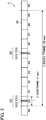
- FIG. 3 is a diagram showing a format of a radio frame F that the macro base station eNB and the small base station PhNB each transmit.
- a variety of radio signals (control signals, user signals, etc.) are transmitted by the base stations (eNB and PhNB) using radio frames F.
- One radio frame F contains ten subframes SF.
- the time length of each subframe SF is 1 millisecond, and the time length of one radio frame F is therefore 10 milliseconds.
- Each subframe SF has one of subframe numbers that range from #0 to #9, the subframe numbers being assigned in rotation to subframes SF in the order of their transmission.
- a synchronization signal SS which indicates a physical cell identity PCI, is transmitted in the first and the sixth subframes SF (SF#0 and SF#5) in a radio frame F.
- a synchronization signal SS is transmitted in a cycle of five subframes (i.e., every 5 milliseconds).
- a physical cell identity PCI indicated by a synchronization signal SS is assigned to each base station (each cell), and is used for various kinds of processing, such as synchronization establishment, cell recognition, channel estimation, data scrambling, etc. (refer to 3GPP TS 36.211 V10.1.0 (2011-03), Chapter 6.11, Synchronization signals).
- a synchronization signal SS includes a PSS (Primary Synchronization Signal), which indicates a local identity of a cell, and an SSS (Secondary Synchronization Signal), which indicates a group identity of the cell. That is, a synchronization signal SS can serve as an identification signal.
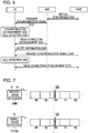
- FIG. 5 is a flow diagram schematically showing a flow of operations for synchronization establishment and cell recognition (cell searching) using a synchronization signal SS (a PSS and an SSS).
- Cell searching includes processing in the first phase and that in the second phase.
- the user device UE calculates correlations between a radio signal received from a base station (e.g., the macro base station eNB) and PSS replica signals stored in the user device UE so as to detect the transmission timing (subframe timing) of a PSS included in the radio signal and the local identity.
- a base station e.g., the macro base station eNB
- PSS replica signals stored in the user device UE so as to detect the transmission timing (subframe timing) of a PSS included in the radio signal and the local identity.
- processing to detect the transmission timing of PSS's may be referred to as "timing-search processing".
- the user device UE calculates correlations between an SSS included in a received radio signal and SSS replica signals stored in the user device UE so as to detect the transmission timing (frame timing) of an SSS included in the radio signal and the group identity.
- the local identity and the group identity which are indicated by synchronization signals SS in received radio signals, are identified.
- the user device UE recognizes the physical cell identity PCI of the base station (eNB or PhNB) that transmits the synchronization signals SS.
- the user device UE calculates correlations over the entirety of the received radio signal.
- the user device UE can, based on the transmission timing detected in the first phase, recognize the location of a synchronization signal SS (and therefore the location of an SSS) in a received radio signal, the user device UE calculates correlations only for the part that corresponds to the SSS in the received radio signal.
- the processing load for calculations in the first phase is therefore much greater than that in the second phase.
- FIG. 6 is an operation flow showing an example of the identifying processing to identify a physical cell identity PCI.
- FIG. 7 is a diagram showing an example of radio signal transmission performed by the macro base station eNB and the small base station PhNB that are synchronized with each other.
- the macro base station eNB and the small base station PhNB of the first embodiment are, as stated above, synchronized with each other. That is, as shown in FIG. 7 , there is no difference between a transmission timing at which the macro base station eNB transmits a synchronization signal SS and a transmission timing at which the small base station PhNB transmits a synchronization signal SS (or, the difference between the transmission timings is much smaller compared with the duration of a radio signal unit (resource element, etc.)).
- the macro base station eNB periodically transmits a synchronization signal SS that indicates the physical cell identity PCI identifying the macro base station eNB at a transmission timing, such as the timings shown in FIGs. 3 and 7 (S10).
- the user device UE based on synchronization signals SS received from the macro base station eNB, performs cell detection (processing to identify a physical cell identity PCI that indicates the macro base station eNB) and synchronization establishment with the macro base station eNB (S20). More specifically, as stated above, the user device UE detects the transmission timing of PSS's and the local identity based on a PSS included in a synchronization signal SS from the macro base station eNB (the first phase).
- the user device UE based on an SSS included in a synchronization signal SS from the macro base station eNB, then detects the transmission timing of SSS's and the group identity so as to identify the transmission timing of synchronization signals SS and the physical cell identity PCI. The user device UE then establishes a radio connection with the macro base station eNB (S30).
- the macro base station eNB notifies the user device UE of synchronization state information related to a synchronization state between the macro base station eNB and the small base station PhNB, which is located nearby, and of frequency information related to an identification signal frequency that the small base station PhNB uses to transmit synchronization signals SS (S40).
- the synchronization state information indicates that "the macro base station eNB and the small base station PhNB are synchronized”.
- the user device UE stores the received synchronization state information and the received frequency information.
- the small base station PhNB periodically transmits a synchronization signal SS that indicates the physical cell identity PCI identifying the small base station PhNB at a transmission timing, such as the timing shown in FIG. 7 (S50).
- the user device UE based on synchronization signals SS received from the small base station PhNB, performs cell detection (processing to identify a physical cell identity PCI that indicates the small base station PhNB) (S60).
- the cell detection described immediately above is performed using the synchronization state information and the frequency information notified at step S40.
- the user device UE when the synchronization state information indicates that "the macro base station eNB and the small base station PhNB are synchronized", the user device UE, without performing timing-search processing for the small base station PhNB, performs, based on the transmission timing of synchronization signals SS transmitted by the macro base station eNB, detection processing to detect the local identity and the group identity, on the identification signal frequency that is indicated by the frequency information and is used by the small base station PhNB. The user device UE then establishes a radio connection with the small base station PhNB (S70).
- the user device UE does not need to search for the location (transmission timing) of a synchronization signal SS included in a radio signal from the small base station PhNB. That is, the user device UE can omit the first phase of cell searching.
- the user device UE can regard the transmission timing of synchronization signals SS at the macro base station eNB obtained at step S20 as the transmission timing of synchronization signals SS at the small base station PhNB to perform cell detection (calculate correlations with the replica signals) because the macro base station eNB and the small base station PhNB are synchronized, as stated above, and the macro base station eNB and the small base station PhNB use a common transmission timing to transmit synchronization signals SS.
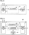
- FIG. 8 is a block diagram showing a configuration of the user device UE according to the first embodiment.
- the user device UE includes a radio communication unit 110, a storage unit 120, and a controller 130.
- the radio communication unit 110 is an element for performing radio communication with the macro base station eNB and with the small base station PhNB.
- the radio communication unit 110 includes transceiving antennas, a receiving circuit for receiving radio signals (radio waves) and converting them to electrical signals, and a transmitting circuit for converting electrical signals, such as control signals and user signals, to radio signals (radio waves) and transmitting them.
- the storage unit 120 stores information related to communication control, in particular, the transmission timing of synchronization signals SS at a base station (e.g., eNB, PhNB) with which the user device UE has established synchronization, the synchronization state information, and the frequency information.
- the controller 130 exchanges user signals and control signals and includes a cell searcher 132.
- the cell searcher 132 performs the above-described types of cell searching; that is, the regular two-phased cell searching ( FIG. 5 ) and cell searching for the small base station PhNB using the transmission timing at the macro base station eNB ( FIG. 6 , etc.).
- the controller 130 and the elements included in the controller 130 are functional blocks accomplished by the fact that a CPU (central processing unit; not shown in the figure), provided in the user device UE, executes a computer program stored in the storage unit 120 and operates in accordance with the computer program.
- FIG. 9 is a block diagram showing a configuration of the macro base station eNB according to the first embodiment.
- the macro base station eNB includes a radio communication unit 210, a network communication unit 220, a storage unit 230, and a controller 240.
- the radio communication unit 210 is an element for performing radio communication with the user device UE, and has a configuration similar to that of the radio communication unit 110 of the user device UE.
- the network communication unit 220 is an element for performing communication with other nodes (the small base station PhNB, the switching center, etc.) in the network NW, and exchanges signals with the other nodes.
- the storage unit 230 stores information related to communication control.
- the controller 240 exchanges user signals and control signals and includes a transmitting unit 242 and an information notifying unit 244.
- the transmitting unit 242 transmits synchronization signals SS that indicate the physical cell identity PCI identifying the macro base station eNB, through the radio communication unit 210.
- the information notifying unit 244 notifies the user device of the synchronization state information and the frequency information through the radio communication unit 210.
- the controller 240 and the elements in the controller 240 are functional blocks accomplished by the fact that a CPU (not shown in the figure), provided in the macro base station eNB, executes a computer program stored in the storage unit 230 and operates in accordance with the computer program.
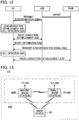
- FIG. 10 is a block diagram showing a configuration of the small base station PhNB according to the first embodiment.
- the small base station PhNB includes a radio communication unit 310, a network communication unit 320, a storage unit 330, and a controller 340.
- the radio communication unit 310 is an element for performing radio communication with the user device UE and has a configuration similar to that of the radio communication unit 210 of the macro base station eNB.
- the network communication unit 320 is an element for performing communication with other nodes (the macro base station eNB, etc.) in the network NW, and exchanges signals with the other nodes.
- the storage unit 330 stores information related to communication control.
- the controller 340 exchanges user signals and control signals and includes a transmitting unit 342.
- the transmitting unit 342 transmits synchronization signals SS that indicate the physical cell identity PCI identifying the small base station PhNB, through the radio communication unit 310.
- the controller 340 and the elements in the controller 340 are functional blocks accomplished by the fact that a CPU (not shown in the figure), provided in the small base station PhNB, executes a computer program stored in the storage unit 330 and operates in accordance with the computer program.
- the user device UE can, even without performing timing-search processing for the small base station PhNB, perform identifying processing to identify the physical cell identity PCI indicated by synchronization signals SS transmitted by the small base station PhNB, based on the transmission timing of synchronization signals SS at the macro base station eNB.
- timing-search processing for the small base station PhNB is omitted, a processing load on the user device UE to recognize the small base station PhNB is reduced.
- the macro base station eNB and the small base station PhNB are synchronized with each other and transmit synchronization signals SS at the same time.
- the small base station PhNB (the transmitting unit 342) transmits a synchronization signal SS at a transmission timing that is delayed from the transmission timing of synchronization signals SS at the macro base station eNB by the length of time that corresponds to a transmission offset value OV.
- identifying processing to identify the physical cell identity PCI of the small base station PhNB is described. Because cell detection and synchronization establishment that the user device UE performs for the macro base station eNB (steps S12 to S32) are similar to steps S10 to S30 in the first embodiment, descriptions thereof are omitted.
- the macro base station eNB notifies the user device UE of the synchronization state information related to a synchronization state between the macro base station eNB and the small base station PhNB, which is located nearby, and of frequency information related to an identification signal frequency that the small base station PhNB uses to transmit synchronization signals SS (S42).
- the synchronization state information indicates the transmission offset value OV for the transmission timing at the macro base station eNB.
- the user device UE stores the received synchronization state information and the received frequency information.
- the small base station PhNB periodically transmits a synchronization signal SS that indicates the physical cell identity PCI identifying the small base station PhNB at a transmission timing, such as the timing shown in FIG. 11 (S52).
- the user device UE based on synchronization signals SS received from the small base station PhNB, performs cell detection (processing to identify the physical cell identity PCI that indicates the small base station PhNB) (S62).
- the cell detection described immediately above is performed using the synchronization state information (the transmission offset value OV) and the frequency information notified at step S42.
- the user device UE without performing timing-search processing for the small base station PhNB, performs detection processing, on the identification signal frequency that is indicated by the frequency information and is used by the small base station PhNB, to detect the local identity and the group identity based on the transmission timing of synchronization signals SS transmitted by the macro base station eNB and the transmission offset value OV.
- the user device UE then establishes a radio connection with the small base station PhNB (S72).
- the user device UE does not need to search for the location (transmission timing) of a synchronization signal SS included in a radio signal from the small base station PhNB. That is, the user device UE can omit the first phase of cell searching.
- This is enabled, as described above, by the fact that the user device UE can obtain the transmission timing of synchronization signals SS at the small base station PhNB by adding the transmission offset value OV to the transmission timing of synchronization signals SS at the macro base station eNB obtained at step S22, because there is a time difference that corresponds to the transmission offset value OV between the transmission timing at the macro base station eNB and that at the small base station PhNB.
- the macro base station eNB and the small base station PhNB are interconnected by an interface (optical fiber, etc.) that can transmit clock signals and are synchronized with each other.
- the small base station PhNB receives synchronization signals SS from the macro base station eNB to synchronize with the macro base station eNB.
- FIG. 13 is a block diagram showing a radio communication system CS according to the third embodiment.
- the small base station PhNB receives synchronization signals SS from the macro base station eNB to detect the transmission timing so as to synchronize with the macro base station eNB.
- a synchronization timing is delayed by the length of time required for radio signals transmitted by the macro base station eNB to reach the small base station PhNB and to be processed.
- the small base station PhNB of the third embodiment therefore, advances the transmission timing of its synchronization signals SS according to the distance from the macro base station eNB.
- FIG. 14 is a block diagram showing a configuration of the small base station PhNB according to the third embodiment.
- the controller 340 of the small base station PhNB further includes a synchronization detecting unit 344, a received power measuring unit 346, and an offset value setter 348.
- the synchronization detecting unit 344 similarly to the cell searcher 132 of the user device UE in the embodiments described above, detects the transmission timing of synchronization signals SS transmitted by the macro base station eNB and provides it to the transmitting unit 342.
- the received power measuring unit 346 measures received power of radio signals (reference signals) received through the radio communication unit 310 from the macro base station eNB.
- the offset value setter 348 sets a transmission offset value OV so that the smaller the received power measured by the received power measuring unit 346 is, the larger the transmission offset value OV is.
- the offset value setter then provides the transmission offset value OV to the transmitting unit 342.
- the transmitting unit 342 transmits a synchronization signal SS of the small base station PhNB at a transmission timing that is advanced from the transmission timing at the macro base station eNB, the transmission timing at the macro base station eNB being provided from the synchronization detecting unit 344, by the length of time that corresponds to the transmission offset value OV provided from the offset value setter 348.
- the small base station PhNB as described above therefore, corrects (advances) its transmission timing according to the distance from the macro base station eNB. As a result, a difference between the transmission timing at the macro base station eNB and the transmission timing at the small base station PhNB is reduced.
- the transmission timing at which the macro base station eNB transmits a synchronization signal SS and the transmission timing at which the small base station PhNB transmits a synchronization signal SS are synchronized with each other ( FIG. 7 ). Because the 168 types of SSS's are not orthogonal to one another, when multiple SSS's are transmitted at the same transmission timing, they interfere with one another.
- the user device UE performs cell searching for the small base station PhNB using the transmission timing at the macro base station eNB as described in the first embodiment ( FIG. 6 ), the user device UE may not, depending on radio environment, etc., be able to identify the group identity (and therefore the physical cell identity PCI) with sufficient accuracy.
- a small base station PhNB transmits a cell-specific signal that includes a signal (identification signal) that indicates the physical cell identity PCI corresponding to the small base station PhNB.
- a cell-specific signal is a signal that is different from a synchronization signal SS; for example, a reference signal other than a synchronization signal SS. Examples of a reference signal include a CRS (Cell Specific Reference Signal), a CSI-RS (CSI Reference Signal), a PRS (Positioning Reference Signal), an MBSFN-RS (MBSFN Reference Signal), etc.
- the CRS for example, has six patterns of frequency shift, and therefore interference due to collision is reduced compared with the SSS. Furthermore, because the CRS has its symbols scattered over the entire system bandwidth, a higher correlation energy can be obtained when correlations are calculated, compared with the SSS.
- a freely chosen type of signal that indicates the physical cell identity PCI corresponding to the small base station PhNB may be used as a cell-specific signal.
- the user device UE In performing cell detection (step S60 in FIG. 6 ), the user device UE (cell searcher 132) identifies the physical cell identity PCI of the small base station PhNB indicated by the identification signal included in a cell-specific signal. A location (transmission timing) of a cell-specific signal is determined relative to a location (transmission timing) of a synchronization signal SS of the small base station PhNB. As stated above, the macro base station eNB and the small base station PhNB are synchronized and have a common transmission timing of synchronization signals SS.
- the user device UE can therefore regard the transmission timing of synchronization signals SS at the macro base station eNB obtained at step S20 as the transmission timing of synchronization signals SS at the small base station PhNB, and can perform cell detection on a cell-specific signal such as described above.
- the user device UE may perform cell detection on a combination of a synchronization signal SS and a cell-specific signal, or on a combination of multiple types of cell-specific signals.
- the user device UE can perform cell detection for the small base station PhNB using a cell-specific signal that is different from a synchronization signal SS, the user device UE can identify the group identity (physical cell identity PCI) with higher accuracy compared with a configuration in which the group identity (physical cell identity PCI) is identified using only SSS's which interfere with one another.
- group identity physical cell identity PCI
- the fifth embodiment relates to details of cell searching for the small base station PhNB using a reference signal (CSI-RS).
- the macro base station eNB (information notifying unit 244) of the fifth embodiment transmits to the user device UE, in addition to the synchronization state information and the frequency information, information related to a configuration of a CSI-RS that the small base station PhNB transmits (reference signal configuration information; CSI-RS Configuration) and a CP length (cyclic prefix length) in radio communication performed by the small base station PHNB.
- reference signal configuration information CSI-RS Configuration
- CP length cyclic prefix length
- a CSI-RS is a reference signal sequence that is generated using various parameters that include a physical cell identity PCI.
- a radio resource (time and frequency) used to transmit a CSI-RS is not fixed and is determined independent of a physical cell identity PCI (refer to 3GPP TS 36.211 V10.1.0 (2011-03 ), Chapter 6.10.1, Cell-specific reference signals).
- the reference signal configuration information indicates a radio resource that is used to transmit a CSI-RS.
- a CP length is a time length of a cyclic prefix.
- a cyclic prefix is a guard interval that is inserted before a valid symbol to avoid effects by a delayed wave in OFDM radio communication.
- a CP length is either "normal” or "extended”.
- a location of the SSS on a radio frame F (location relative to the PSS) is determined according to the CP length (not shown in FIGs. 3 and 7 ).
- the macro base station eNB (information notifying unit 244) notifies the user device UE, as described above, of synchronization state information, frequency information, reference signal configuration information, and CP length information (S40).
- the frequency information of the present embodiment indicates, as identification signal frequencies, a frequency that is used to transmit synchronization signals SS and a frequency that is used to transmit CSI-RS's.
- the small base station PhNB periodically transmits a synchronization signal SS that indicates the physical cell identity PCI identifying the small base station PhNB and a CSI-RS such as described above (S50).
- the user device UE based on synchronization signals SS and CSI-RS's received from the small base station PhNB, performs cell detection (S60).
- the cell detection mentioned immediately above is performed using the synchronization state information, the frequency information, the reference signal configuration information, and the CP length information.
- the user device UE when the synchronization state information indicates that "the macro base station eNB and the small base station PhNB are synchronized", the user device UE, without performing timing-search processing for the small base station PhNB, based on the transmission timing of synchronization signals SS transmitted by the macro base station eNB and the reference signal configuration information, performs detection processing, on the identification signal frequency that is indicated by the frequency information and is used by the small base station PhNB, to detect the local identity, the group identity, and a CSI-RS. The user device UE then establishes a radio connection with the small base station PhNB (S70).
- the operations described above can be used in the configuration of the second embodiment, in which the transmission timing at the small base station PhNB is offset.
- the above configuration can be used with a freely chosen type of signal that can be used to identify a cell (another reference signal, a signal for discovering a small cell (discovery signal), etc.).
- the user device UE Because the user device UE is notified of the reference signal configuration information by the macro base station eNB, the user device UE knows a radio resource that is used to transmit a CSI-RS. In the cell detection at step S60, therefore, the user device UE can perform detection processing to detect the CSI-RS (can calculate correlations between the CSI-RS transmitted by the small base station PhNB and replica signals stored in the user device UE). Because the user device UE is notified of the CP length information by the macro base station eNB, the user device UE knows a location of an SSS on a radio frame F (a location relative to a PSS). In the cell detection at step S60, therefore, the user device UE does not need to identify whether the location (transmission timing) of the SSS corresponds to the "normal" CP length or to the "extended" CP length.
- the user device UE performs cell detection for the small base station PhNB using a reference signal (CSI-RS)
- the user device UE can identify a cell with higher accuracy compared with a configuration in which cell detection is performed using only SSS's which interfere with one another.
- CSI-RS reference signal
- Synchronization between the macro base station eNB and the small base station PhNB may not always be accurate. A situation can be assumed in which the accuracy of synchronization between the macro base station eNB and the small base station PhNB is low. In such a case, even when the synchronization state information indicates that "the macro base station eNB and the small base station PhNB are synchronized" as in the first embodiment, in reality the transmission timing at which the macro base station eNB transmits a synchronization signal SS and the transmission timing at which the small base station PhNB transmits a synchronization signal SS may be out of synchronization.
- the user device UE instead of performing the first phase of cell searching (timing-search processing) for the small base station PhNB, performs detection processing (tracking processing) that is based on the transmission timing of synchronization signals SS transmitted by the macro base station eNB. More specifically, in the cell detection for the small base station PhNB (step S60 in FIG.
- the user device UE when the synchronization state information indicates that "the macro base station eNB and the small base station PhNB are synchronized", the user device UE performs timing-search processing over a predetermined period (that is, over a limited time period) that includes the transmission timing of synchronization signals SS transmitted by the macro base station eNB (e.g., 5 microseconds centering on the transmission timing at the macro base station eNB) so as to identify the transmission timing at the small base station PhNB, and then performs the cell detection described above.
- a predetermined period that is, over a limited time period
- the above-described situation can also arise in the second embodiment, in which the transmission timing at the small base station PhNB is offset. That is, when the accuracy of synchronization between the macro base station eNB and the small base station PhNB is low, a transmission timing that is delayed from the transmission timing at the macro base station eNB by the length of time that corresponds to the transmission offset value OV indicated by the synchronization state information (the calculated transmission timing at the small base station PhNB), and the actual transmission timing of synchronization signals SS transmitted by the small base station PhNB, may be out of synchronization.
- the user device UE therefore, in the cell detection for the small base station PhNB (step S62 in FIG. 12 ), performs timing-search processing over a predetermined period (that is, over a limited time period) that includes the transmission timing that is delayed from the transmission timing of synchronization signals SS transmitted by the macro base station eNB by the length of time corresponding to the transmission offset value OV (that is, the calculated transmission timing at the small base station PhNB) (e.g., performs timing-search processing over 5 microseconds centering on the calculated transmission timing at the small base station PhNB) so as to identify the transmission timing at the small base station PhNB, and then performs the cell detection described above.
- a predetermined period that is, over a limited time period
- OV that is, the calculated transmission timing at the small base station PhNB
- the above configuration achieves technical effects similar to those of the embodiments described above even when the accuracy of synchronization between the macro base station eNB and the small base station PhNB is low.
- the small base stations PhNB transmit common reference signals (e.g., CSI-RS) at the same transmission timing. These reference signals are synchronization reference signals for the user device UE to establish synchronization with the small base stations PhNB. Additionally, as shown in FIG. 16 , the small base stations PhNB transmit reference signals (e.g., CSI-RS) that are different in transmission timing or in sequence. These reference signals are identification reference signals for the user device UE to identify each of the small base stations PhNB.
- CSI-RS synchronization reference signals for the user device UE to establish synchronization with the small base stations PhNB.
- reference signals e.g., CSI-RS
- These reference signals are identification reference signals for the user device UE to identify each of the small base stations PhNB.
- the macro base station eNB and the small base stations PhNB are synchronized, it may be the macro base station eNB alone that transmits the synchronization reference signals. In this case, each of the small base stations PhNB transmits at least identification reference signals that identify itself.
- the user device UE can detect synchronization with the small base stations PhNB simultaneously. Furthermore, because the small base stations PhNB transmit different identification reference signals, the user device UE can identify each of the small base stations PhNB.
- FIG. 17 a user device UE performs radio communication directly with another user device UE in the radio communication system CS.
- FIG. 18 is a block diagram showing a configuration of the user device UE according to the eighth embodiment.
- the controller 130 of the user device UE further includes a terminal transmitting unit 134 that transmits a terminal discovery signal that indicates a terminal identifier that identifies the user device.
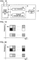
- FIG. 19 is a diagram showing terminal discovery signals transmitted by multiple user devices UE.
- a user device UE (terminal transmitting unit 134) transmits a terminal discovery signal using a resource block RB that is allocated to the user device UE.
- different hatching patterns on resource blocks RB correspond to different user devices UE.
- a terminal discovery signal is an uplink signal that is transmitted using SC-FDMA. Because signals from a user device UE are transmitted using a single-carrier, a peak-to-average power ratio (PAPR) can be lowered.
- PAPR peak-to-average power ratio
- FIG. 20 is a diagram showing identification signals that small base stations PhNB transmit.
- a small base station PhNB transmitting unit 342, using multiple resource blocks RB, transmits identification signals that have a common signal format with terminal discovery signals transmitted by a user device UE. Having "a common signal format" indicates that identification signals and terminal discovery signals have common characteristics such as signal length, the number of signal sequences that can be chosen, and modulation-demodulation method for signal exchange.
- hatching patterns on resource blocks RB vary for different transmission-source small base stations PhNB.
- multiple resource blocks RB can be transmitted on a single time axis or on a single frequency axis. According to the above configuration, by the use of multiple resource blocks RB, a time-domain or frequency-domain diversity effect can be obtained.
- identification signals that small base stations PhNB transmit are preferably transmitted using SC-FDMA. Additionally, the identification signals are preferably transmitted using a frequency band that can be used by user devices UE to receive signals.
- the small base station PhNB may transmit identification signals by SC-FDMA using a downlink frequency.
- multiple single-carriers may be used to transmit identification signals.
- the small base station PhNB may transmit identification signals using the common frequency.
- Identification signals may be transmitted using a dedicated radio resource. Transmission of signals other than identification signals is preferably stopped for a dedicated radio resource.
- terminal discovery signals used to detect a user device UE and identification signals used to detect a small base station PhNB have a common signal format.
- the user device UE can, therefore, perform detection of a small base station PhNB and perform detection of another user device UE, using a single mechanism.
- cell detection for a small base station PhNB is performed using a reference signal (CSI-RS).
- cell detection for a small base station PhNB is performed based on a hopping pattern (identification signal pattern) formed by multiple CSI-RS's.
- a small base station PhNB (transmitting unit 342) of the ninth embodiment transmits CSI-RS's according to a hopping pattern that is unique to the small base station PhNB.
- a hopping pattern indicates a configuration of CSI-RS's in each of multiple subframes SF.
- the user device UE can identify the small base station PhNB based on the configuration (hopping pattern) of CSI-RS's over subframes SF.
- FIG. 21 is a diagram showing a configuration of CSI-RS's in a resource block RB.
- a resource block RB includes resource elements RE. From among resource elements RE that are assigned with numbers ranging from 0 to 19 (RE#0 to RE#19) in FIG. 21 , CSI-RS's are transmitted using resource elements RE corresponding to at least one of the numbers. There may be resource blocks RB that are not used to transmit CSI-RS's.
- FIG. 22 is a diagram showing an example of a hopping pattern.
- the small base station PhNB as shown in the figure, transmits CSI-RS's in the order (hopping pattern) of RE#5, RE#9, RE#6, RE#3, and RE#8.
- the user device UE has been notified by the macro base station eNB of hopping patterns that small base stations PhNB use. The user device UE can therefore identify each of the small base stations PhNB by detecting the hopping patterns.
- a cycle of a hopping pattern may be equal to a conventional cycle of CSI-RS's (e.g., 80 ms), or may be different; for example, a cycle may be set to be equal to the integral multiple of a conventional cycle of CSI-RS's.
- small base stations PhNB may transmit common CSI-RS's for a synchronization purpose, and each of the small base stations PhNB may transmit different CSI-RS's for an identification purpose.
- a greater number of small base stations PhNB can be installed because more identification patterns are provided, compared with a configuration in which small base stations PhNB are identified based only on resource elements RE that are used to transmit CSI-RS's.
- the radio communication system CS (the network NW) in the above embodiments is a heterogeneous network that includes a macro base station eNB and a small base station PhNB
- a homogeneous network that includes base stations of a single type e.g., macro base station eNB
- the number of frequency band used may be one.
- a macro base station eNB and a small base station PhNB are synchronized through an interface, such as optical fiber etc., that can transmit clock signals, or through a radio interface.
- a method can be chosen freely, however, for a macro base station eNB and a small base station PhNB to establish synchronization.
- a macro base station eNB and a small base station PhNB may establish synchronization based on time indicated by radio waves transmitted by a GPS satellite (GPS signals).
- the macro base station eNB may notify the user device UE of an identity list that indicates physical cell identities PCI of small base stations PhNB that are located around the macro base station eNB, by adding the identity list to the synchronization state information (step S40 and step S42).
- the user device UE (cell searcher 132) may perform cell detection (calculate correlations with replica signals) with respect to the small base stations PhNB corresponding to the physical cell identities PCI indicated by the notified identity list (step S60 and step S62). In this case, because the number of physical cell identities PCI for which the user device UE is to perform cell detection is limited, a processing load on the user device UE is even further reduced.
- a small base station PhNB is identified using a physical cell identity PCI.
- An identifier to identify a small base station PhNB may be freely chosen.
- An identifier may be used that is dedicated to identify a small base station PhNB and is different from a physical cell identity PCI.
- the macro base station eNB (information notifying unit 244) notifies the user device UE of each of the transmission offset values OV as the synchronization state information.
- a single piece of reference signal configuration information (CSI-RS Configuration) may be set, or multiple pieces of reference signal configuration information may be set.
- CSI-RS Configuration When multiple pieces of reference signal configuration information are set for a single small base station PhNB or transmission point, a cell can be identified with higher accuracy compared with a situation in which a single piece of reference signal configuration information is set.
- the user device UE performs cell searching (timing-search processing) using synchronization signals SS.
- the user device UE can perform cell searching (timing-search processing) using freely chosen signals that are transmitted periodically.
- the reference signals that are described in the fourth embodiment can be used for cell searching.
- Cell searching may be performed using a combination of synchronization signals SS and at least one type of the reference signals mentioned above or using a combination of multiple types of reference signals.
- a hopping pattern may be used in which resource blocks RB that are used to transmit CSI-RS's, as well as resource elements RE in a subframe SF, hop.
- resource blocks RB that are used to transmit CSI-RS's, as well as resource elements RE in a subframe SF, hop may be used.
- a greater number of small base stations PhNB can be installed because more hopping patterns are provided.
- the new-version user device UEN identifying a small base station PhNB using a hopping pattern of CSI-RS's ("FOR UEN" in FIG. 24 ), the old-version user device UEO identifying a small base station PhNB based only on resource elements RE that are used to transmit CSI-RS's ("FOR UEO" in FIG. 24 ).
- the user device UE is a freely chosen device that can perform radio communication with the macro base station eNB and the small base station PhNB.
- the user device UE may be a cell phone terminal, e.g., a feature phone or a smart phone, a desktop type personal computer, a laptop personal computer, a UMPC (ultra-mobile personal computer), a portable game machine, or another type of radio terminal.
- functions executed by the CPU may instead be executed by hardware or by a programmable logic device, such as an FPGA (Field Programmable Gate Array) and a DSP (Digital Signal Processor).
- a programmable logic device such as an FPGA (Field Programmable Gate Array) and a DSP (Digital Signal Processor).
Claims (10)
- Funkkommunikationssystem (CS), umfassend:Basisstationen, die eine erste Basisstation (eNB) und eine zweite Basisstation (PhNB) aufweisen, wobei die erste Basisstation Funkkommunikation unter Verwendung eines ersten Frequenzbands und Abdecken einer ersten Zelle (C1), die durch eine erste Zellidentität identifiziert ist, ausführt, wobei die zweite Basisstation Funkkommunikation unter Verwendung eines zweiten Frequenzbands und Abdecken einer zweiten Zelle (C2), die durch eine zweite Zellidentität identifiziert ist, ausführt; undeine Nutzervorrichtung (UE), die konfiguriert ist, um Funkkommunikation mit jeder der Basisstationen auszuführen,wobei die erste Basisstation (eNB) aufweist:eine erste Übertragungseinheit (242), die konfiguriert ist, um an einem ersten Übertragungszeitpunkt ein erstes Synchronisationssignal zu übertragen, das die erste Zellidentität angibt, die die erste Zelle identifiziert, die von der ersten Basisstation abgedeckt ist,wobei die zweite Basisstation (PhNB) aufweist:eine zweite Übertragungseinheit (342), die konfiguriert ist, um ein Identifizierungssignal zu übertragen, das die zweite Zellidentität angibt, die die zweite Zelle identifiziert, die von der zweiten Basisstation abgedeckt ist,wobei die Nutzervorrichtung (UE) aufweist:eine Zellsucheinheit (132), die konfiguriert ist, um den ersten Übertragungszeitpunkt beruhend auf dem ersten Synchronisationssignal, das von der ersten Basisstation empfangen wurde, zu erfassen und eine Zeitpunkt-Suchverarbeitung auszuführen, die eine Synchronisation mit der ersten Basisstation herstellt,wobei die erste Basisstation (eNB) weiter aufweist:eine Informationsbenachrichtigungseinheit (244), die konfiguriert ist, um der Nutzervorrichtung Synchronisationszustandsinformationen in Verbindung mit einem Synchronisationszustand zwischen der ersten Basisstation und der zweiten Basisstation, und Frequenzinformationen in Verbindung mit einer Identifizierungssignalfrequenz, die die zweite Basisstation verwendet, um das Identifizierungssignal zu übertragen, mitzuteilen, wobei die Identifizierungssignalfrequenz im zweiten Frequenzband aufgewiesen ist, wobei die Synchronisationszustandsinformationen angeben, ob die erste Basisstation und die zweite Basisstation synchronisiert sind, oder einen Übertragungsversatzwert für den ersten Übertragungszeitpunkt an der ersten Basisstation angibt, undwobei die Zellsucheinheit (132) der Nutzervorrichtung beruhend auf den Synchronisationszustandsinformationen von der ersten Basisstation konfiguriert ist, um eine Identifizierungsverarbeitung über die Identifizierungssignalfrequenz auszuführen, die von den Frequenzinformationen angegeben wird, um die zweite Zellidentität zu identifizieren, die von dem Identifizierungssignal angegeben wird.
- Funkkommunikationssystem nach Anspruch 1,
wobei die erste Basisstation und die zweite Basisstation miteinander synchronisiert sind, um Funkkommunikation auszuführen,
wobei die zweite Übertragungseinheit (342) der zweiten Basisstation konfiguriert ist, um ein zweites Synchronisationssignal an einem zweiten Übertragungszeitpunkt zu übertragen,
wobei die Synchronisationszustandsinformationen, die von der Informationsbenachrichtigungseinheit (244) der ersten Basisstation mitgeteilt werden, angeben, ob die erste Basisstation und die zweite Basisstation synchronisiert sind, und
wobei, wenn die Synchronisationszustandsinformationen angeben, dass die erste Basisstation und die zweite Basisstation synchronisiert sind, die Zellsucheinheit (132) der Nutzervorrichtung, ohne eine Zeitpunkt-Suchverarbeitung für die zweite Basisstation auszuführen, konfiguriert ist, um eine Identifizierungsverarbeitung beruhend auf dem ersten Übertragungszeitpunkt auszuführen, um die zweite Zellidentität zu identifizieren, die von dem Identifizierungssignal angegeben wird. - Funkkommunikationssystem nach Anspruch 1,
wobei die erste Basisstation und die zweite Basisstation miteinander synchronisiert sind, um Funkkommunikation auszuführen,
wobei die zweite Übertragungseinheit (342) der zweiten Basisstation konfiguriert ist, um ein zweites Synchronisationssignal an einem zweiten Übertragungszeitpunkt zu übertragen,
wobei die Synchronisationszustandsinformationen, die von der Informationsbenachrichtigungseinheit der ersten Basisstation mitgeteilt werden, angeben, ob die erste Basisstation und die zweite Basisstation synchronisiert sind, und
wobei wenn die Synchronisationszustandsinformationen angeben, dass die erste Basisstation und die zweite Basisstation synchronisiert sind, die Zellsucheinheit (132) der Nutzervorrichtung konfiguriert ist, um den zweiten Übertragungszeitpunkt durch Ausführen einer Zeitpunkt-Suchverarbeitung für die zweite Basisstation über einen vorbestimmten Zeitraum, der den ersten Übertragungszeitpunkt aufweist, zu identifizieren, und eine Identifizierungsverarbeitung beruhend auf dem zweiten Übertragungszeitpunkt auszuführen, um die zweite Zellidentität zu identifizieren, die von dem Identifizierungssignal angegeben wird. - Funkkommunikationssystem nach Anspruch 1,
wobei die zweite Übertragungseinheit (342) der zweiten Basisstation konfiguriert ist, um das Identifizierungssignal an einem zweiten Übertragungszeitpunkt zu übertragen, wobei der zweite Übertragungszeitpunkt ein Zeitpunkt ist, der vom ersten Übertragungszeitpunkt an der ersten Basisstation um eine Zeitlänge versetzt ist, die dem Übertragungsversatzwert entspricht,
wobei die Synchronisationszustandsinformationen, die von der Informationsbenachrichtigungseinheit der ersten Basisstation mitgeteilt werden, den Übertragungsversatzwert für den ersten Übertragungszeitpunkt an der ersten Basisstation angeben, und
wobei die Zellsucheinheit (132) der Nutzervorrichtung, ohne eine Zeitpunkt-Suchverarbeitung für die zweite Basisstation auszuführen, konfiguriert ist, um eine Identifizierungsverarbeitung beruhend auf dem ersten Übertragungszeitpunkt und dem Übertragungsversatzwert, der von den Synchronisationszustandsinformationen angegeben wird, auszuführen, um die zweite Zellidentität zu identifizieren, die von dem Identifizierungssignal angegeben wird. - Funkkommunikationssystem nach Anspruch 1,
wobei die zweite Übertragungseinheit (342) der zweiten Basisstation konfiguriert ist, um das Identifizierungssignal an einem zweiten Übertragungszeitpunkt zu übertragen, wobei der zweite Übertragungszeitpunkt ein Zeitpunkt ist, der vom ersten Übertragungszeitpunkt an der ersten Basisstation um eine Zeitlänge versetzt ist, die dem Übertragungsversatzwert entspricht,
wobei die Synchronisationszustandsinformationen, die von der Informationsbenachrichtigungseinheit der ersten Basisstation mitgeteilt werden, den Übertragungsversatzwert für den ersten Übertragungszeitpunkt an der ersten Basisstation angeben, und
wobei die Zellsucheinheit (132) der Nutzervorrichtung konfiguriert ist, um den zweiten Übertragungszeitpunkt durch Ausführen einer Zeitpunkt-Suchverarbeitung für die zweite Basisstation über einen vorbestimmten Zeitraum zu identifizieren, der einen Übertragungszeitpunkt aufweist, der vom ersten Übertragungszeitpunkt um eine Zeitlänge versetzt ist, die dem Übertragungsversatzwert entspricht, der von den Synchronisationszustandsinformationen angegeben wird, und eine Identifizierungsverarbeitung beruhend auf dem zweiten Übertragungszeitpunkt auszuführen, um die zweite Zellidentität zu identifizieren, die von dem Identifizierungssignal angegeben wird. - Funkkommunikationssystem nach Anspruch 1, wobei die zweite Basisstation (PhNB) weiter aufweist:eine Empfangsleistung-Messeinheit (346), die konfiguriert ist, um eine Empfangsleistung von Funksignalen zu messen, die von der ersten Basisstation empfangen werden; undeine Versatzwert-Festlegungseinheit (348), die konfiguriert ist, um den Übertragungsversatzwert festzulegen, sodass der Übertragungsversatzwert mit abnehmender Empfangsleistung, die von der Empfangsleistung-Messeinheit gemessen wird, zunimmt,wobei die zweite Übertragungseinheit (342) der zweiten Basisstation konfiguriert ist, um das Identifizierungssignal an einem zweiten Übertragungszeitpunkt zu übertragen, wobei der zweite Übertragungszeitpunkt ein Zeitpunkt ist, der vom ersten Übertragungszeitpunkt an der ersten Basisstation um eine Zeitlänge vorverlegt ist, die dem Übertragungsversatzwert entspricht,wobei die Synchronisationszustandsinformationen, die von der Informationsbenachrichtigungseinheit der ersten Basisstation mitgeteilt werden, angeben, ob die erste Basisstation und die zweite Basisstation synchronisiert sind, undwobei, wenn die Synchronisationszustandsinformationen angeben, dass die erste Basisstation und die zweite Basisstation synchronisiert sind, die Zellsucheinheit (132) der Nutzervorrichtung, ohne eine Zeitpunkt-Suchverarbeitung für die zweite Basisstation auszuführen, konfiguriert ist, um eine Identifizierungsverarbeitung beruhend auf dem ersten Übertragungszeitpunkt auszuführen, um die zweite Zellidentität zu identifizieren, die von dem Identifizierungssignal angegeben wird.
- Funkkommunikationssystem nach Anspruch 2,
wobei die Synchronisationszustandsinformationen weiter eine Identitätsliste aufweisen, die zweite Zellidentitäten angeben, die den zweiten Basisstationen entsprechen, und
wobei die Zellsucheinheit (132) der Nutzervorrichtung konfiguriert ist, um die Identifizierungsverarbeitung nur für die zweiten Basisstationen auszuführen, die den zweiten Zellidentitäten entsprechen, die von der Identitätsliste angegeben werden. - Funkkommunikationssystem nach Anspruch 1,
wobei die Nutzervorrichtung weiter eine terminale Übertragungseinheit (134) aufweist, die konfiguriert ist, um ein terminales Entdeckungssignal zu übertragen, das eine terminale Kennung angibt, die die Nutzervorrichtung identifiziert, und
wobei die zweite Übertragungseinheit (342) der zweiten Basisstation konfiguriert ist, um das Identifizierungssignal zu übertragen, das ein gemeinsames Signalformat mit dem terminalen Entdeckungssignal hat. - Funkkommunikationssystem nach Anspruch 1,
wobei die zweite Übertragungseinheit (342) der zweiten Basisstation konfiguriert ist, um das Identifizierungssignal gemäß einem Identifizierungssignalmuster zu übertragen, wobei das Identifizierungssignalmuster eine Konfiguration des Identifizierungssignals in jedem der Unterframes angibt und die zweite Basisstation identifiziert. - Kommunikationssteuerverfahren in einem Funkkommunikationssystem, das umfasst:Basisstationen, die eine erste Basisstation (eNB) und eine zweite Basisstation (PhNB) aufweisen, wobei die erste Basisstation Funkkommunikation unter Verwendung eines ersten Frequenzbands und Abdecken einer ersten Zelle, die durch eine erste Zellidentität identifiziert ist, ausführt, die zweite Basisstation Funkkommunikation unter Verwendung eines zweiten Frequenzbands und Abdecken einer zweiten Zelle, die durch eine zweite Zellidentität identifiziert ist, ausführt; und eine Nutzervorrichtung (UE), die Funkkommunikation mit jeder der Basisstationen ausführt,das Kommunikationssteuerverfahren umfassend:in der ersten Basisstation Übertragen (S10, S12) an einem ersten Übertragungszeitpunkt eines ersten Synchronisationssignals, das die erste Zellidentität angibt, die die erste Zelle identifiziert, die von der ersten Basisstation abgedeckt ist,in der zweiten Basisstation Übertragen (S50, S52) eines Identifizierungssignals, das der zweiten Zellidentität entspricht, die die zweite Zelle identifiziert, die von der zweiten Basisstation abgedeckt ist,in der Nutzervorrichtung Erfassen des ersten Übertragungszeitpunkts beruhend auf dem ersten Synchronisationssignal, das von der ersten Basisstation empfangen wird, und Ausführen (S20, S22) einer Zeitpunkt-Suchverarbeitung, die die Synchronisation mit der ersten Basisstation herstellt,in der ersten Basisstation Mitteilung (S40, S42) an die Nutzervorrichtung von Synchronisationszustandsinformationen in Verbindung mit einem Synchronisationszustand zwischen der ersten Basisstation und der zweiten Basisstation, und Frequenzinformation in Verbindung mit einer Identifizierungssignalfrequenz, die die zweite Basisstation verwendet, um das Identifizierungssignal zu übertragen, wobei die Identifizierungssignalfrequenz im zweiten Frequenzband aufgewiesen ist, wobei die Synchronisationszustandsinformationen angeben, ob die erste Basisstation und die zweite Basisstation synchronisiert sind, oder einen Übertragungsversatzwert für den ersten Übertragungszeitpunkt an der ersten Basisstation angibt, undin der Nutzervorrichtung unter Verwendung der Synchronisationszustandsinformationen von der ersten Basisstation Ausführen (S60, S62) einer Identifizierungsverarbeitung über die Identifizierungssignalfrequenz, die von den Frequenzinformationen angegeben wird, um die zweite Zellidentität zu identifizieren, die in dem Identifizierungssignal aufgewiesen ist.
Applications Claiming Priority (3)
| Application Number | Priority Date | Filing Date | Title |
|---|---|---|---|
| JP2013001826 | 2013-01-09 | ||
| JP2013099391A JP5809660B2 (ja) | 2013-01-09 | 2013-05-09 | 無線通信システムおよび通信制御方法 |
| PCT/JP2013/078531 WO2014109105A1 (ja) | 2013-01-09 | 2013-10-22 | 無線通信システムおよび通信制御方法 |
Publications (3)
| Publication Number | Publication Date |
|---|---|
| EP2945428A1 EP2945428A1 (de) | 2015-11-18 |
| EP2945428A4 EP2945428A4 (de) | 2016-01-27 |
| EP2945428B1 true EP2945428B1 (de) | 2017-09-27 |
Family
ID=51166770
Family Applications (1)
| Application Number | Title | Priority Date | Filing Date |
|---|---|---|---|
| EP13870740.1A Active EP2945428B1 (de) | 2013-01-09 | 2013-10-22 | Radiokommunikationssystem und kommunikationssteuerungsverfahren |
Country Status (6)
| Country | Link |
|---|---|
| US (1) | US9603111B2 (de) |
| EP (1) | EP2945428B1 (de) |
| JP (1) | JP5809660B2 (de) |
| CN (1) | CN105122891B (de) |
| BR (1) | BR112015012836A2 (de) |
| WO (1) | WO2014109105A1 (de) |
Families Citing this family (27)
| Publication number | Priority date | Publication date | Assignee | Title |
|---|---|---|---|---|
| JP2015223005A (ja) * | 2013-01-09 | 2015-12-10 | 株式会社Nttドコモ | 無線通信システムおよび通信制御方法 |
| RU2015135523A (ru) * | 2013-02-28 | 2017-03-03 | Сони Корпорейшн | Устройство управления связью, способ управления связью и терминал |
| CN105340329A (zh) * | 2013-04-03 | 2016-02-17 | 谷歌技术控股有限责任公司 | 用于小区发现的方法和设备 |
| KR101460491B1 (ko) * | 2013-04-03 | 2014-11-11 | 주식회사 이노와이어리스 | 멀티-셀 환경에서 lte 셀 검출 장치 |
| US9986520B2 (en) * | 2013-07-22 | 2018-05-29 | Zte Wistron Telecom Ab | Method and system for cell synchronization and synchronization cell indication |
| JP6309736B2 (ja) * | 2013-10-09 | 2018-04-11 | 株式会社Nttドコモ | 無線基地局、ユーザ端末及び無線通信方法 |
| IN2013CH05862A (de) * | 2013-12-16 | 2015-06-19 | Samsung R&D Inst India – Bangalore Private Ltd | |
| EP3142430B1 (de) * | 2014-05-30 | 2020-06-24 | Huawei Technologies Co., Ltd. | Synchronisationsverfahren, synchronisationsvorrichtung und basisstation |
| US20170215205A1 (en) * | 2014-07-23 | 2017-07-27 | Ntt Docomo, Inc. | Radio base station, user terminal and radio communication method |
| CN106576256B (zh) * | 2014-07-31 | 2020-04-07 | 宇龙计算机通信科技(深圳)有限公司 | 时频同步维持的方法、时频同步维持的系统和终端 |
| US9871568B2 (en) * | 2014-08-11 | 2018-01-16 | Intel Corporation | System detection in a high frequency band radio access technology architecture |
| US9374796B2 (en) * | 2014-10-10 | 2016-06-21 | Qualcomm Incorporated | Channel structure for a cellular internet of things system |
| CN106304346B (zh) * | 2015-05-15 | 2019-07-19 | 电信科学技术研究院 | 一种同步信号的发送、接收方法及装置 |
| CN111541527B (zh) | 2015-11-20 | 2022-04-22 | 华为技术有限公司 | 一种下行同步的方法、装置及系统 |
| US10091609B2 (en) * | 2016-03-28 | 2018-10-02 | Qualcomm Incorporated | Enhancing PRS searches via runtime conditions |
| JP6847986B2 (ja) | 2016-07-01 | 2021-03-24 | オッポ広東移動通信有限公司Guangdong Oppo Mobile Telecommunications Corp., Ltd. | 信号検出方法及び装置 |
| WO2018063051A1 (en) * | 2016-09-30 | 2018-04-05 | Telefonaktiebolaget Lm Ericsson (Publ) | Network, network node, user equipment and method therein for establishing active mode beam to idle mode cells neighbour relations in a wireles communication network |
| EP3520477B1 (de) | 2016-09-30 | 2019-11-06 | Telefonaktiebolaget LM Ericsson (PUBL) | Netzwerk, netzwerkknoten und verfahren darin zur verbindungshandhabung in einem drahtloskommunikationsnetzwerk |
| CN112073099A (zh) * | 2016-10-15 | 2020-12-11 | 上海朗帛通信技术有限公司 | 一种支持同步信号的ue、基站中的方法和装置 |
| CN108616300B (zh) | 2017-01-06 | 2024-03-08 | 华为技术有限公司 | 一种信道状态信息测量的配置方法及相关设备 |
| JP6832794B2 (ja) * | 2017-06-05 | 2021-02-24 | ルネサスエレクトロニクス株式会社 | 無線通信システム |
| EP3678424A4 (de) * | 2017-08-29 | 2021-04-14 | NTT DoCoMo, Inc. | Benutzergerät, basisstation und drahtloskommunikationsverfahren |
| US11765672B2 (en) * | 2017-10-02 | 2023-09-19 | Sony Corporation | Method and device for synchronization and measurement in a radio communication system |
| WO2019125750A1 (en) * | 2017-12-18 | 2019-06-27 | Kyocera Corporation | Downlink timing advanced for common synchronization signal acquisition |
| JP7019820B2 (ja) * | 2017-12-18 | 2022-02-15 | 京セラ株式会社 | 共通同期チャネルを使用したmtcのシステム取得時間の短縮 |
| TW201931813A (zh) * | 2018-01-09 | 2019-08-01 | 財團法人資訊工業策進會 | 無線通訊裝置及其時頻同步方法與非暫態電腦可讀取紀錄媒體 |
| US11109387B2 (en) * | 2019-02-15 | 2021-08-31 | Nokia Technologies Oy | Interference management |
Family Cites Families (7)
| Publication number | Priority date | Publication date | Assignee | Title |
|---|---|---|---|---|
| JP2009188612A (ja) | 2008-02-05 | 2009-08-20 | Mitsubishi Electric Corp | 移動体通信システム |
| US8711811B2 (en) * | 2008-06-19 | 2014-04-29 | Telefonaktiebolaget L M Ericsson (Publ) | Identifying multi-component carrier cells |
| JP2010045545A (ja) * | 2008-08-11 | 2010-02-25 | Ntt Docomo Inc | ユーザ装置及びセルサーチ方法 |
| US8472954B2 (en) * | 2008-12-26 | 2013-06-25 | Sharp Kabushiki Kaisha | Base station device, mobile station device, communication system, and communication method |
| CN103906250B (zh) * | 2009-02-02 | 2018-06-22 | 三菱电机株式会社 | 移动体通信系统 |
| JP5595952B2 (ja) * | 2011-03-10 | 2014-09-24 | 株式会社Nttドコモ | セルサーチ装置及び方法並びに移動局 |
| CN102958151B (zh) * | 2011-08-15 | 2015-08-19 | 财团法人工业技术研究院 | 载波聚合的无线网络系统与基站、通信装置及同步方法 |
-
2013
- 2013-05-09 JP JP2013099391A patent/JP5809660B2/ja active Active
- 2013-10-22 EP EP13870740.1A patent/EP2945428B1/de active Active
- 2013-10-22 WO PCT/JP2013/078531 patent/WO2014109105A1/ja active Application Filing
- 2013-10-22 CN CN201380069976.8A patent/CN105122891B/zh active Active
- 2013-10-22 US US14/759,257 patent/US9603111B2/en active Active
- 2013-10-22 BR BR112015012836A patent/BR112015012836A2/pt not_active IP Right Cessation
Non-Patent Citations (1)
| Title |
|---|
| None * |
Also Published As
| Publication number | Publication date |
|---|---|
| WO2014109105A1 (ja) | 2014-07-17 |
| US9603111B2 (en) | 2017-03-21 |
| CN105122891B (zh) | 2018-06-22 |
| JP5809660B2 (ja) | 2015-11-11 |
| US20160088579A1 (en) | 2016-03-24 |
| CN105122891A (zh) | 2015-12-02 |
| EP2945428A4 (de) | 2016-01-27 |
| BR112015012836A2 (pt) | 2017-07-11 |
| JP2014150517A (ja) | 2014-08-21 |
| EP2945428A1 (de) | 2015-11-18 |
Similar Documents
| Publication | Publication Date | Title |
|---|---|---|
| EP2945428B1 (de) | Radiokommunikationssystem und kommunikationssteuerungsverfahren | |
| CN102379141B (zh) | 用于无线传输系统上的用户设备位置确定的方法和系统 | |
| KR101608348B1 (ko) | 확장가능한 캐리어 배치에서 효율적인 스펙트럼 사용을 위한 방법 및 장치 | |
| CN103379537B (zh) | Lte和lte-a的基于相关性的小区搜索和测量 | |
| US20210410097A1 (en) | Methods, Apparatus and Machine-Readable Mediums Relating to Reference Signals for Positioning in a Wireless Network | |
| EP3222017B1 (de) | Rahmenformat für zellensuchverfahren | |
| CN105659694B (zh) | 移动台及接收质量测量方法 | |
| EP2842367B1 (de) | Vorrichtung und verfahren zur angabe von zelleninformationen in einem drahtlosen netzwerk | |
| EP2965581B1 (de) | Verfahren und gerät zur kontrolle von interferenzen | |
| RU2726172C1 (ru) | Способ и устройство для обнаружения сигнала | |
| KR20160138553A (ko) | 참조 신호 검출 방법과 수신 방법, 사용자 장비, 및 기지국 | |
| TWI693840B (zh) | 接收訊號強度指示測量之方法及其使用者設備 | |
| CN108293195A (zh) | 用于管理无线通信网络中的信令的无线设备、无线网络节点及在其中执行的方法 | |
| US20230007603A1 (en) | Methods for enabling a reduced bandwidth wireless device to access a cell | |
| JP6507020B2 (ja) | セルサーチ方法及びユーザ装置 | |
| US20190074941A1 (en) | Method for estimating index of symbol in wireless communication system and apparatus therefor | |
| US10154426B2 (en) | Method for performing measurement and device using same | |
| JP2015223005A (ja) | 無線通信システムおよび通信制御方法 | |
| WO2022265547A1 (en) | Network node and method for restraining false preambles | |
| WO2018158967A1 (ja) | 基地局装置およびその通信方法 | |
| KR20170124088A (ko) | 이동 통신 시스템에서 초기 동기 신호 송수신 방법 및 장치 |
Legal Events
| Date | Code | Title | Description |
|---|---|---|---|
| PUAI | Public reference made under article 153(3) epc to a published international application that has entered the european phase |
Free format text: ORIGINAL CODE: 0009012 |
|
| 17P | Request for examination filed |
Effective date: 20150716 |
|
| AK | Designated contracting states |
Kind code of ref document: A1 Designated state(s): AL AT BE BG CH CY CZ DE DK EE ES FI FR GB GR HR HU IE IS IT LI LT LU LV MC MK MT NL NO PL PT RO RS SE SI SK SM TR |
|
| AX | Request for extension of the european patent |
Extension state: BA ME |
|
| A4 | Supplementary search report drawn up and despatched |
Effective date: 20160107 |
|
| RIC1 | Information provided on ipc code assigned before grant |
Ipc: H04W 48/08 20090101AFI20151222BHEP Ipc: H04W 56/00 20090101ALI20151222BHEP Ipc: H04W 88/10 20090101ALI20151222BHEP Ipc: H04W 16/32 20090101ALI20151222BHEP |
|
| DAX | Request for extension of the european patent (deleted) | ||
| GRAP | Despatch of communication of intention to grant a patent |
Free format text: ORIGINAL CODE: EPIDOSNIGR1 |
|
| INTG | Intention to grant announced |
Effective date: 20170522 |
|
| GRAS | Grant fee paid |
Free format text: ORIGINAL CODE: EPIDOSNIGR3 |
|
| GRAA | (expected) grant |
Free format text: ORIGINAL CODE: 0009210 |
|
| AK | Designated contracting states |
Kind code of ref document: B1 Designated state(s): AL AT BE BG CH CY CZ DE DK EE ES FI FR GB GR HR HU IE IS IT LI LT LU LV MC MK MT NL NO PL PT RO RS SE SI SK SM TR |
|
| REG | Reference to a national code |
Ref country code: GB Ref legal event code: FG4D |
|
| REG | Reference to a national code |
Ref country code: CH Ref legal event code: EP |
|
| REG | Reference to a national code |
Ref country code: AT Ref legal event code: REF Ref document number: 933069 Country of ref document: AT Kind code of ref document: T Effective date: 20171015 |
|
| REG | Reference to a national code |
Ref country code: IE Ref legal event code: FG4D |
|
| REG | Reference to a national code |
Ref country code: FR Ref legal event code: PLFP Year of fee payment: 5 |
|
| REG | Reference to a national code |
Ref country code: DE Ref legal event code: R096 Ref document number: 602013027336 Country of ref document: DE |
|
| PG25 | Lapsed in a contracting state [announced via postgrant information from national office to epo] |
Ref country code: SE Free format text: LAPSE BECAUSE OF FAILURE TO SUBMIT A TRANSLATION OF THE DESCRIPTION OR TO PAY THE FEE WITHIN THE PRESCRIBED TIME-LIMIT Effective date: 20170927 Ref country code: NO Free format text: LAPSE BECAUSE OF FAILURE TO SUBMIT A TRANSLATION OF THE DESCRIPTION OR TO PAY THE FEE WITHIN THE PRESCRIBED TIME-LIMIT Effective date: 20171227 Ref country code: HR Free format text: LAPSE BECAUSE OF FAILURE TO SUBMIT A TRANSLATION OF THE DESCRIPTION OR TO PAY THE FEE WITHIN THE PRESCRIBED TIME-LIMIT Effective date: 20170927 Ref country code: LT Free format text: LAPSE BECAUSE OF FAILURE TO SUBMIT A TRANSLATION OF THE DESCRIPTION OR TO PAY THE FEE WITHIN THE PRESCRIBED TIME-LIMIT Effective date: 20170927 |
|
| REG | Reference to a national code |
Ref country code: NL Ref legal event code: MP Effective date: 20170927 |
|
| REG | Reference to a national code |
Ref country code: LT Ref legal event code: MG4D |
|
| REG | Reference to a national code |
Ref country code: AT Ref legal event code: MK05 Ref document number: 933069 Country of ref document: AT Kind code of ref document: T Effective date: 20170927 |
|
| PG25 | Lapsed in a contracting state [announced via postgrant information from national office to epo] |
Ref country code: BG Free format text: LAPSE BECAUSE OF FAILURE TO SUBMIT A TRANSLATION OF THE DESCRIPTION OR TO PAY THE FEE WITHIN THE PRESCRIBED TIME-LIMIT Effective date: 20171227 Ref country code: LV Free format text: LAPSE BECAUSE OF FAILURE TO SUBMIT A TRANSLATION OF THE DESCRIPTION OR TO PAY THE FEE WITHIN THE PRESCRIBED TIME-LIMIT Effective date: 20170927 Ref country code: RS Free format text: LAPSE BECAUSE OF FAILURE TO SUBMIT A TRANSLATION OF THE DESCRIPTION OR TO PAY THE FEE WITHIN THE PRESCRIBED TIME-LIMIT Effective date: 20170927 Ref country code: GR Free format text: LAPSE BECAUSE OF FAILURE TO SUBMIT A TRANSLATION OF THE DESCRIPTION OR TO PAY THE FEE WITHIN THE PRESCRIBED TIME-LIMIT Effective date: 20171228 |
|
| PG25 | Lapsed in a contracting state [announced via postgrant information from national office to epo] |
Ref country code: NL Free format text: LAPSE BECAUSE OF FAILURE TO SUBMIT A TRANSLATION OF THE DESCRIPTION OR TO PAY THE FEE WITHIN THE PRESCRIBED TIME-LIMIT Effective date: 20170927 |
|
| PG25 | Lapsed in a contracting state [announced via postgrant information from national office to epo] |
Ref country code: RO Free format text: LAPSE BECAUSE OF FAILURE TO SUBMIT A TRANSLATION OF THE DESCRIPTION OR TO PAY THE FEE WITHIN THE PRESCRIBED TIME-LIMIT Effective date: 20170927 Ref country code: ES Free format text: LAPSE BECAUSE OF FAILURE TO SUBMIT A TRANSLATION OF THE DESCRIPTION OR TO PAY THE FEE WITHIN THE PRESCRIBED TIME-LIMIT Effective date: 20170927 Ref country code: CZ Free format text: LAPSE BECAUSE OF FAILURE TO SUBMIT A TRANSLATION OF THE DESCRIPTION OR TO PAY THE FEE WITHIN THE PRESCRIBED TIME-LIMIT Effective date: 20170927 |
|
| PG25 | Lapsed in a contracting state [announced via postgrant information from national office to epo] |
Ref country code: IT Free format text: LAPSE BECAUSE OF FAILURE TO SUBMIT A TRANSLATION OF THE DESCRIPTION OR TO PAY THE FEE WITHIN THE PRESCRIBED TIME-LIMIT Effective date: 20170927 Ref country code: EE Free format text: LAPSE BECAUSE OF FAILURE TO SUBMIT A TRANSLATION OF THE DESCRIPTION OR TO PAY THE FEE WITHIN THE PRESCRIBED TIME-LIMIT Effective date: 20170927 Ref country code: IS Free format text: LAPSE BECAUSE OF FAILURE TO SUBMIT A TRANSLATION OF THE DESCRIPTION OR TO PAY THE FEE WITHIN THE PRESCRIBED TIME-LIMIT Effective date: 20180127 Ref country code: SK Free format text: LAPSE BECAUSE OF FAILURE TO SUBMIT A TRANSLATION OF THE DESCRIPTION OR TO PAY THE FEE WITHIN THE PRESCRIBED TIME-LIMIT Effective date: 20170927 Ref country code: SM Free format text: LAPSE BECAUSE OF FAILURE TO SUBMIT A TRANSLATION OF THE DESCRIPTION OR TO PAY THE FEE WITHIN THE PRESCRIBED TIME-LIMIT Effective date: 20170927 Ref country code: AT Free format text: LAPSE BECAUSE OF FAILURE TO SUBMIT A TRANSLATION OF THE DESCRIPTION OR TO PAY THE FEE WITHIN THE PRESCRIBED TIME-LIMIT Effective date: 20170927 |
|
| REG | Reference to a national code |
Ref country code: CH Ref legal event code: PL |
|
| REG | Reference to a national code |
Ref country code: DE Ref legal event code: R097 Ref document number: 602013027336 Country of ref document: DE |
|
| PG25 | Lapsed in a contracting state [announced via postgrant information from national office to epo] |
Ref country code: MC Free format text: LAPSE BECAUSE OF FAILURE TO SUBMIT A TRANSLATION OF THE DESCRIPTION OR TO PAY THE FEE WITHIN THE PRESCRIBED TIME-LIMIT Effective date: 20170927 |
|
| REG | Reference to a national code |
Ref country code: IE Ref legal event code: MM4A |
|
| PG25 | Lapsed in a contracting state [announced via postgrant information from national office to epo] |
Ref country code: DK Free format text: LAPSE BECAUSE OF FAILURE TO SUBMIT A TRANSLATION OF THE DESCRIPTION OR TO PAY THE FEE WITHIN THE PRESCRIBED TIME-LIMIT Effective date: 20170927 Ref country code: LI Free format text: LAPSE BECAUSE OF NON-PAYMENT OF DUE FEES Effective date: 20171031 Ref country code: CH Free format text: LAPSE BECAUSE OF NON-PAYMENT OF DUE FEES Effective date: 20171031 Ref country code: LU Free format text: LAPSE BECAUSE OF NON-PAYMENT OF DUE FEES Effective date: 20171022 |
|
| PLBE | No opposition filed within time limit |
Free format text: ORIGINAL CODE: 0009261 |
|
| STAA | Information on the status of an ep patent application or granted ep patent |
Free format text: STATUS: NO OPPOSITION FILED WITHIN TIME LIMIT |
|
| REG | Reference to a national code |
Ref country code: BE Ref legal event code: MM Effective date: 20171031 |
|
| PG25 | Lapsed in a contracting state [announced via postgrant information from national office to epo] |
Ref country code: PL Free format text: LAPSE BECAUSE OF FAILURE TO SUBMIT A TRANSLATION OF THE DESCRIPTION OR TO PAY THE FEE WITHIN THE PRESCRIBED TIME-LIMIT Effective date: 20170927 Ref country code: BE Free format text: LAPSE BECAUSE OF NON-PAYMENT OF DUE FEES Effective date: 20171031 |
|
| 26N | No opposition filed |
Effective date: 20180628 |
|
| REG | Reference to a national code |
Ref country code: FR Ref legal event code: PLFP Year of fee payment: 6 |
|
| PG25 | Lapsed in a contracting state [announced via postgrant information from national office to epo] |
Ref country code: MT Free format text: LAPSE BECAUSE OF NON-PAYMENT OF DUE FEES Effective date: 20171022 |
|
| PG25 | Lapsed in a contracting state [announced via postgrant information from national office to epo] |
Ref country code: IE Free format text: LAPSE BECAUSE OF NON-PAYMENT OF DUE FEES Effective date: 20171022 |
|
| PG25 | Lapsed in a contracting state [announced via postgrant information from national office to epo] |
Ref country code: SI Free format text: LAPSE BECAUSE OF FAILURE TO SUBMIT A TRANSLATION OF THE DESCRIPTION OR TO PAY THE FEE WITHIN THE PRESCRIBED TIME-LIMIT Effective date: 20170927 |
|
| PG25 | Lapsed in a contracting state [announced via postgrant information from national office to epo] |
Ref country code: HU Free format text: LAPSE BECAUSE OF FAILURE TO SUBMIT A TRANSLATION OF THE DESCRIPTION OR TO PAY THE FEE WITHIN THE PRESCRIBED TIME-LIMIT; INVALID AB INITIO Effective date: 20131022 |
|
| PG25 | Lapsed in a contracting state [announced via postgrant information from national office to epo] |
Ref country code: CY Free format text: LAPSE BECAUSE OF FAILURE TO SUBMIT A TRANSLATION OF THE DESCRIPTION OR TO PAY THE FEE WITHIN THE PRESCRIBED TIME-LIMIT Effective date: 20170927 |
|
| PG25 | Lapsed in a contracting state [announced via postgrant information from national office to epo] |
Ref country code: MK Free format text: LAPSE BECAUSE OF FAILURE TO SUBMIT A TRANSLATION OF THE DESCRIPTION OR TO PAY THE FEE WITHIN THE PRESCRIBED TIME-LIMIT Effective date: 20170927 |
|
| PG25 | Lapsed in a contracting state [announced via postgrant information from national office to epo] |
Ref country code: TR Free format text: LAPSE BECAUSE OF FAILURE TO SUBMIT A TRANSLATION OF THE DESCRIPTION OR TO PAY THE FEE WITHIN THE PRESCRIBED TIME-LIMIT Effective date: 20170927 |
|
| PG25 | Lapsed in a contracting state [announced via postgrant information from national office to epo] |
Ref country code: PT Free format text: LAPSE BECAUSE OF FAILURE TO SUBMIT A TRANSLATION OF THE DESCRIPTION OR TO PAY THE FEE WITHIN THE PRESCRIBED TIME-LIMIT Effective date: 20170927 |
|
| PG25 | Lapsed in a contracting state [announced via postgrant information from national office to epo] |
Ref country code: AL Free format text: LAPSE BECAUSE OF FAILURE TO SUBMIT A TRANSLATION OF THE DESCRIPTION OR TO PAY THE FEE WITHIN THE PRESCRIBED TIME-LIMIT Effective date: 20170927 |
|
| P01 | Opt-out of the competence of the unified patent court (upc) registered |
Effective date: 20230510 |
|
| PGFP | Annual fee paid to national office [announced via postgrant information from national office to epo] |
Ref country code: GB Payment date: 20231020 Year of fee payment: 11 |
|
| PGFP | Annual fee paid to national office [announced via postgrant information from national office to epo] |
Ref country code: FR Payment date: 20231026 Year of fee payment: 11 Ref country code: FI Payment date: 20231020 Year of fee payment: 11 Ref country code: DE Payment date: 20231020 Year of fee payment: 11 |