EP2945278A1 - Statisches Erregersystem für Generatoren - Google Patents
Statisches Erregersystem für Generatoren Download PDFInfo
- Publication number
- EP2945278A1 EP2945278A1 EP14167894.6A EP14167894A EP2945278A1 EP 2945278 A1 EP2945278 A1 EP 2945278A1 EP 14167894 A EP14167894 A EP 14167894A EP 2945278 A1 EP2945278 A1 EP 2945278A1
- Authority
- EP
- European Patent Office
- Prior art keywords
- generators
- generator
- voltage
- field
- control device
- Prior art date
- Legal status (The legal status is an assumption and is not a legal conclusion. Google has not performed a legal analysis and makes no representation as to the accuracy of the status listed.)
- Granted
Links
- 230000003068 static effect Effects 0.000 title claims abstract description 35
- 238000004804 winding Methods 0.000 claims abstract description 19
- 230000000052 comparative effect Effects 0.000 claims description 21
- 230000005284 excitation Effects 0.000 claims description 21
- 238000004364 calculation method Methods 0.000 claims description 13
- 238000005259 measurement Methods 0.000 claims description 12
- 238000000034 method Methods 0.000 claims description 9
- 230000003247 decreasing effect Effects 0.000 claims description 3
- 238000004519 manufacturing process Methods 0.000 claims description 3
- 238000005516 engineering process Methods 0.000 abstract description 2
- 230000001052 transient effect Effects 0.000 description 11
- 230000001360 synchronised effect Effects 0.000 description 8
- 239000003990 capacitor Substances 0.000 description 7
- 238000010586 diagram Methods 0.000 description 5
- 230000000694 effects Effects 0.000 description 2
- 238000012544 monitoring process Methods 0.000 description 2
- 230000001133 acceleration Effects 0.000 description 1
- 238000004891 communication Methods 0.000 description 1
- 230000002950 deficient Effects 0.000 description 1
- 230000003111 delayed effect Effects 0.000 description 1
- 238000001514 detection method Methods 0.000 description 1
- 230000005611 electricity Effects 0.000 description 1
- 238000012986 modification Methods 0.000 description 1
- 230000004048 modification Effects 0.000 description 1
- 238000010248 power generation Methods 0.000 description 1
- 239000007787 solid Substances 0.000 description 1
- 230000001960 triggered effect Effects 0.000 description 1
Images


Classifications
-
- H—ELECTRICITY
- H02—GENERATION; CONVERSION OR DISTRIBUTION OF ELECTRIC POWER
- H02P—CONTROL OR REGULATION OF ELECTRIC MOTORS, ELECTRIC GENERATORS OR DYNAMO-ELECTRIC CONVERTERS; CONTROLLING TRANSFORMERS, REACTORS OR CHOKE COILS
- H02P9/00—Arrangements for controlling electric generators for the purpose of obtaining a desired output
- H02P9/02—Details
-
- H—ELECTRICITY
- H02—GENERATION; CONVERSION OR DISTRIBUTION OF ELECTRIC POWER
- H02J—CIRCUIT ARRANGEMENTS OR SYSTEMS FOR SUPPLYING OR DISTRIBUTING ELECTRIC POWER; SYSTEMS FOR STORING ELECTRIC ENERGY
- H02J3/00—Circuit arrangements for ac mains or ac distribution networks
- H02J3/04—Circuit arrangements for ac mains or ac distribution networks for connecting networks of the same frequency but supplied from different sources
- H02J3/08—Synchronising of networks
-
- H—ELECTRICITY
- H02—GENERATION; CONVERSION OR DISTRIBUTION OF ELECTRIC POWER
- H02P—CONTROL OR REGULATION OF ELECTRIC MOTORS, ELECTRIC GENERATORS OR DYNAMO-ELECTRIC CONVERTERS; CONTROLLING TRANSFORMERS, REACTORS OR CHOKE COILS
- H02P9/00—Arrangements for controlling electric generators for the purpose of obtaining a desired output
- H02P9/10—Control effected upon generator excitation circuit to reduce harmful effects of overloads or transients, e.g. sudden application of load, sudden removal of load, sudden change of load
-
- H—ELECTRICITY
- H02—GENERATION; CONVERSION OR DISTRIBUTION OF ELECTRIC POWER
- H02P—CONTROL OR REGULATION OF ELECTRIC MOTORS, ELECTRIC GENERATORS OR DYNAMO-ELECTRIC CONVERTERS; CONTROLLING TRANSFORMERS, REACTORS OR CHOKE COILS
- H02P9/00—Arrangements for controlling electric generators for the purpose of obtaining a desired output
- H02P9/14—Arrangements for controlling electric generators for the purpose of obtaining a desired output by variation of field
- H02P9/26—Arrangements for controlling electric generators for the purpose of obtaining a desired output by variation of field using discharge tubes or semiconductor devices
- H02P9/30—Arrangements for controlling electric generators for the purpose of obtaining a desired output by variation of field using discharge tubes or semiconductor devices using semiconductor devices
Definitions
- the present invention relates to the field of generator technology. It relates in particular to a static exciter system for controlling the field voltage of generators and to a method for controlling the field voltage of generators.
- Static exciter systems for feeding the field winding creating a magnetic excitation field for a generator and thus supplying the generator excitation are widely used. These systems are determined by their robustness and a short response time. In case of grid faults it is important that generators connected to the grid, especially synchronous generators mainly used for power generation, remain in synchronism. The ability of synchronous generators to keep a synchronous run in an electric grid system is referred to as transient stability in a power system. Power system transient stability is a complex problem which involves many phenomena. Sometimes local measurements at one generator do not capture the complexity of system wide problems and grid faults cannot be determined by this. Monitoring and controlling system wide problems beyond monitoring and controlling separate generators can be addressed by means of Wide Area Measurement Systems (WAMS) recently developed.
- WAMS Wide Area Measurement Systems
- the patent EP 1 805 887 B1 describes an ultracapacitor excitation booster to improve the transient stability of synchronous generators in case of grid faults.
- Such an excitation booster system is described below in more detail with reference to Fig. 1 .
- adding excitation boosters to the generators as well as other influences at the grid, and controlling the generators by terminal voltage may deteriorate the grid system stability. It is observed that generators accelerate when a grid fault occurs. Further, is has been observed that some generator rotors accelerate with respect to a comparative value whereas other generators decelerate.
- applying excitation booster systems to the grid system and thereby influencing the field voltage of the generator rotor might thus lead to braking the rotor speed.
- the braking of some generator rotors in a system of connected generators increases the speed deviation with respect to the comparative value.
- the static exciter system sets the field voltage of the excitation field of the rotors of at least two generators.
- a dynamic excitation system is assigned to each generator for production of a DC voltage in the field winding of a generator rotor, the static exciter system is connected to the field winding and together with the field winding form an exciter circuit for emission of electrical energy in case of a grid system fault.
- the static exciter system setting the field voltage can be applied advantageously to a plurality of generators driven by an exciter circuit connected to an electric grid.
- the static exciter system increases the field voltage of a generator which accelerates regarding a comparative value while the static exciter system does not increase the field voltage of a generator which decelerates regarding a comparative value.
- the comparative value is set to a system specific value of the system containing several generators.
- the comparative value of the rotor speed is especially the center of inertia (COI) as this value indicates a status at which the system works in a stable condition.
- COI value is known in the state of the art.
- the kinetic energy referred to the COI is responsible to pull the generators out of synchronism.
- Fig. 1 shows a circuit of a static exciter system 20 according to the state of the art.
- the control device 1 according to the invention introduced in Fig. 4 can be applied to such a static exciter system 20 by way of example.
- the static exciter system 20 comprises a generator 16 with a field winding 17, which is connected to a grid system 34 via a busbar 19 and a machine transformer 11.
- the field winding 17 is supplied with a field current If from the static exciter system 20, which essentially includes an exciter transformer 12 followed by a thyristor bridge 18 which is fitted with thyristors 21.
- the thyristor bridge 18 is driven by an automatic voltage regulator (AVR) 14, which receives as input variables: on the one hand via a voltage transformer 13 the generator voltage applied to the busbar 19, and on the other hand via a current transformer 15 the current flowing in the exciter system 20.
- AVR automatic voltage regulator
- the output side of the thyristor bridge 18 is connected to the field winding 17 which form together an exciter circuit.
- a diode 22 is installed in the forward-bias direction in the exciter circuit.
- a chargeable capacitance 23 can be connected by a switch 24 in parallel with the diode 22, with the capacitance 23 being connected in the reverse-bias direction of the diode 22.
- the capacitance 23 can be charged via a charging unit 25 connected to the capacitance 23.
- the switch 24 can be driven in various ways, as is indicated by various dashed lines in Fig. 1 .
- the diode 22 carries the field current If flowing as direct current DC, and has no influence at all on the operation of the exciter circuit.
- the capacitance 23 which, for example, is formed from so-called ultracapacitors or supercapacitors, is held at a predetermined capacitor voltage U CO by the charging unit 25. The polarity of the capacitor charge corresponds to the reverse-biased direction of the diode 22.
- the excitation system 20 described can also be denominated as an excitation booster having the essential features of the diode 22 and the capacitance 23 connected thereto energizing the exciter circuit for a short time in case of voltage drops in the electric grid. If the terminal voltage of the generator 16 is below a lower voltage threshold, the switch 24 is switched on and the voltage of the capacitance 23 is applied to the field winding 17. Conversely, if the terminal voltage of the generator 16 is above an upper voltage threshold, the switch 24 is switched off. The field voltage is then boosted by the excitation system 20, for instance when shortages in the electric grid occur and thus the voltage drops at the generator side.
- the method of operation of the AVR can continue unchanged.
- the additional capacitor feed is additionally processed via the exciter current detection, which is always present in the AVR.
- the desired voltage shift is achieved by precharging of the capacitance 23.
- the charging voltage may be up to two or more times, in particular up to three or more times, the rated value of the exciter voltage.
- the desired duration of the support is set via the capacitance value.
- the installed support time varies in the range of 1 to 20s.
- ultracapacitors or supercapacitors are used to form the capacitance 23 for example.
- Ultracapacitors such as these which, for example, have a capacitance of 2600 or 2700 F at a rated voltage of 2.5 V.
- the diode 22 is installed as a disk-type diode. Failure results in an internal short circuit, which has no effect on the operation of the exciter system 20.
- the switch 24 can be provided with a fuse link connected in series in order to provide protection against connection to a defective diode.
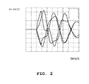
- Fig. 2 shows signals of a system of four generators 16 after a grid fault by way of example, which generators 16 are connected via communication lines, commonly building a Wide Area Measurement System (WAMS) measuring quantities of the connected generators and transmitting this measured data. Shown is the time in seconds in the horizontal axis and the relation of the rotation speeds of the generators 16 in the vertical axis indicating a speed deviation. As is visible in Fig. 2 the relations of the speed deviations of the four generators 16 are up to 2.5* 10 -3 in this example in which no static exciter system 20 stabilizes the system of generators 16. The static exciter system 20 disclosed here reduces the speed differences between the generators 16 and therefore reduces the deviation with respect to a comparative value.
- WAMS Wide Area Measurement System
- the rotation speed of the rotors of the generators 16 is measured.
- the rotation speed can indicate a fault in the electric grid, especially when several rotation speeds are compared as is done here. Further, the rotation speed data can be used as input signals to a control device 1 as described below.
- Fig. 3 shows a block diagram with two schematic generators 16 connected to a dynamic excitation system 28.
- the generators 16 are shown in a schematic way, the dynamic excitation system 28 comprises in this example an insulated-gate bipolar transistor (IGBT) 48, a capacitance 23, and a diode 22 shown in Fig. 4 .
- the dynamic excitation system 28 is a part of the static exciter system 20 described in detail under Fig. 1 above.
- the dynamic excitation system 28 is fed by the control device 1, as described in more detail under Fig. 4 .
- the dynamic excitation system 28 is connected to a thyristor bridge 18, in Fig. 3 shown as a single block diagram. Similar to Fig.
- each thyristor bridge 18 is connected to the electric grid via a transformer 11 or 11, respectively. Furthermore, data lines feed a calculation unit 40 from the exciter transformer 12 via a Phasor Measurement Unit (PMU) 38.
- the calculation unit 40 calculates a comparative value as input signal for the control device 1. In this example the calculation unit 40 thus receives signals from two generators 16 for sake of ease, a system with a variety of generators 16 connected and feeding signals to the calculation unit 40 is applicable.
- the calculated comparative value characterizes a state in which the system of connected generators 16 is in a stable condition regarding the stability of the grid.
- the comparative value is also referred to as center of inertia of the grid.
- the elements described above are connected to an electric grid via machine transformers 11, 11', the generators 16 are commonly connected via electric connections to the grid, the calculation unit 40 is connected via telecommunication lines to the Wide Area Measurement System (WAMS) providing data regarding power system transient stability. This data is especially useful for controlling electric grid faults.
- WAMS Wide Area Measurement System
- Fig. 4 shows a block diagram of an example of the invention with a control device 1 feeding a signal via a Wide Area Measurement System (WAMS).
- the control device 1 is hereby distant to most of the generators 16 connected to the WAMS and receives and transmits signals from and to the WAMS, respectively.
- the input signal x i to the control device 1 is a signal derived from the generator terminal voltage and current of a generator 16 connected to the WAMS at which the control device 1 is connected.
- the busbar 19 shown in Fig. 1 forms part of the WAMS.
- the second input signal x COI to the control device 1 comes from the calculation unit 40 fed by the Phasor Measurement Units (PMU) 38 and is added to the signal x i at an adding element 42.
- PMU Phasor Measurement Units
- the PMU 38 is a measurement device that provides voltage angle measurements synchronized to a common time reference.
- the signal x COI takes into account the different contributions of each synchronous generator 16 to the transient stability of the overall power system commonly comprising several generators 16.
- the signals fed to the adding element 42 are signals indicating a speed deviation.
- the first signal is in this alternative a speed deviation of a rotor generator, the second signal is a speed deviation of a comparative value derived from the speed of the variety of generators 16 connected.
- the signal from the adding element 42 is fed to a controller 43 in which a decision is done whether to drive the dynamic exciter system 28.
- a Pulse Width Modulator (PWM) 44 is connected receiving a signal v cap also from the dynamic exciter system 28.
- the output of the PWM 44 is connected to a driver 46 which drives the dynamic exciter system 28.
- the dynamic exciter system 28 in this example comprises a diode 22 connected in parallel to a capacitance 23 with an IGBT as a switch 24 having a freewheeling diode 31 connected between collector and emitter of the IGBT.
- the voltage stored in the capacitance 23 is added to the field winding 17 when a fault occurs.
- a thyristor bridge 18, here consisting of six thyristors are connected to the emitter side of the IGBT.
- the output of the thyristor bridge 18 is connected to the synchronous generator field winding 17, as is described under Fig. 1 , which generator 16 is also connected to the dynamic exciter system 28. These connections are basis of the field voltage of the connected generator 16.
- the thyristor bridge 18 has further three outputs according to the three current phases connected to the grid via an exciter transformer 12.
- the control device 1 modulates the voltage of the capacitance 23, in this example an ultracapacitor, by means of commuting the transistor circuit 48 of Fig. 4 , which is similar to the solid state switch 24 of the static exciter system 20 of Fig. 1 .
- the field voltage of each of the connected generators 16 can be increased if necessary.
- the control device 1 increases the field voltage of the generators 16 that are accelerating with respect to a comparative value whereas the control device 1 does not supply additional voltage to the generators 16 decelerating with respect to the comparative value.
- the effect from this is that the transient stability of the system comprised mainly by a multitude of generators 16 is improved.
- the control device 1 is directed to reduce the speed deviations compared to a comparative value for each generator 16.
- speed deviations responsible for pulling the system from several generators 16 out of synchronism are reduced which are proportional to the transient kinetic energy. Therefore, the control device 1 contributes to the stability of the generator system by taking into account the stability situation of the generator system provided with data from remote measurements by busbars 19.
- the described static exciter system 20 ensures the continuity and quality of electricity supply. Any type of failure in the grid does not lead to a loss of transient stability of the connected generators 16. The ability of the generator 16 to remain connected to the grid in case of an external fault is improved. The requirement is especially useful in connection with grid codes defining official requirements for grid requirements. Further, the static exciter system disclosed here has demonstrated to improve the critical clearing time after a severe disturbance in the system of generators 16.
Priority Applications (5)
| Application Number | Priority Date | Filing Date | Title |
|---|---|---|---|
| EP14167894.6A EP2945278B1 (de) | 2014-05-12 | 2014-05-12 | Statisches Erregersystem für Generatoren |
| US14/705,409 US9735719B2 (en) | 2014-05-12 | 2015-05-06 | Static exciter system for generators |
| RU2015117607A RU2682917C2 (ru) | 2014-05-12 | 2015-05-08 | Система статического возбудителя для генераторов |
| CA2891065A CA2891065C (en) | 2014-05-12 | 2015-05-11 | Static exciter system for generators |
| CN201510238567.7A CN105099306B (zh) | 2014-05-12 | 2015-05-12 | 用于发电机的静态励磁机系统 |
Applications Claiming Priority (1)
| Application Number | Priority Date | Filing Date | Title |
|---|---|---|---|
| EP14167894.6A EP2945278B1 (de) | 2014-05-12 | 2014-05-12 | Statisches Erregersystem für Generatoren |
Publications (2)
| Publication Number | Publication Date |
|---|---|
| EP2945278A1 true EP2945278A1 (de) | 2015-11-18 |
| EP2945278B1 EP2945278B1 (de) | 2021-03-03 |
Family
ID=50685808
Family Applications (1)
| Application Number | Title | Priority Date | Filing Date |
|---|---|---|---|
| EP14167894.6A Active EP2945278B1 (de) | 2014-05-12 | 2014-05-12 | Statisches Erregersystem für Generatoren |
Country Status (5)
| Country | Link |
|---|---|
| US (1) | US9735719B2 (de) |
| EP (1) | EP2945278B1 (de) |
| CN (1) | CN105099306B (de) |
| CA (1) | CA2891065C (de) |
| RU (1) | RU2682917C2 (de) |
Families Citing this family (11)
| Publication number | Priority date | Publication date | Assignee | Title |
|---|---|---|---|---|
| US10027119B2 (en) | 2016-05-28 | 2018-07-17 | PXiSE Energy Solutions, LLC | Decoupling synchrophasor based control system for multiple distributed energy resources |
| US10615604B2 (en) | 2016-05-28 | 2020-04-07 | PXiSE Energy Solutions, LLC | Decoupling synchrophasor based control system for distributed energy resources |
| US10452032B1 (en) | 2016-09-08 | 2019-10-22 | PXiSE Energy Solutions, LLC | Optimizing power contribution of distributed energy resources for real time power demand scheduling |
| US10599175B1 (en) | 2017-02-28 | 2020-03-24 | PXiSE Energy Solutions, LLC | Time synchronized frequency and voltage regulation of electric power balancing areas |
| CN107643487A (zh) * | 2017-10-31 | 2018-01-30 | 广东电网有限责任公司电力科学研究院 | 一种测试发电机转子时间常数的实用装置及方法 |
| US10990072B2 (en) | 2017-11-28 | 2021-04-27 | PXiSE Energy Solutions, LLC | Maintaining power grid stability using predicted data |
| CN108590857B (zh) * | 2018-04-17 | 2022-05-13 | 章礼道 | 变速同步电机驱动压气机的重型燃气轮机 |
| RU2752780C1 (ru) * | 2020-12-15 | 2021-08-03 | Общество с ограниченной ответственностью «ТРАНСМАШ» | Программно-аппаратные решения по управлению IGBT модулями на основе драйвера на микроконтроллере |
| RU2758996C1 (ru) * | 2020-12-29 | 2021-11-08 | Публичное акционерное общество "ОДК - Уфимское моторостроительное производственное объединение" (ПАО "ОДК-УМПО") | Способ управления трехфазным синхронным генератором |
| US11056912B1 (en) | 2021-01-25 | 2021-07-06 | PXiSE Energy Solutions, LLC | Power system optimization using hierarchical clusters |
| CN116404924B (zh) * | 2023-06-09 | 2023-09-08 | 南方电网调峰调频发电有限公司检修试验分公司 | 一种励磁系统的控制参数调节设备、方法、装置及介质 |
Citations (5)
| Publication number | Priority date | Publication date | Assignee | Title |
|---|---|---|---|---|
| WO2008012853A1 (en) * | 2006-07-26 | 2008-01-31 | Piero Godio | Synchronous electric generator |
| EP2182207A2 (de) * | 2008-10-31 | 2010-05-05 | General Electric Company | Breitbereich-Übertragungssteuerung von Windparks |
| EP1805887B1 (de) | 2004-10-28 | 2011-01-19 | Alstom Technology Ltd | Statisches erregersystem für einen generator sowie verfahren zum betrieb eines solchen erregersystems |
| US20120175876A1 (en) * | 2009-05-20 | 2012-07-12 | Pendray John R | Control of an engine-driven generator to address transients of an electrical power grid connected thereto |
| CN103577691A (zh) * | 2013-10-30 | 2014-02-12 | 国家电网公司 | 一种电网仿真中孤立电网频率计算方法 |
Family Cites Families (12)
| Publication number | Priority date | Publication date | Assignee | Title |
|---|---|---|---|---|
| SE321028B (de) * | 1965-06-29 | 1970-02-23 | Asea Ab | |
| US4701690A (en) * | 1985-11-27 | 1987-10-20 | Basler Electric Company | Transfer apparatus, regulating apparatus and methods |
| JPS62285698A (ja) * | 1986-06-04 | 1987-12-11 | Hitachi Ltd | 車両用交流発電機 |
| US4743814A (en) * | 1987-02-06 | 1988-05-10 | Sankey Edwin W | Static power conversion for adding DC motors |
| RU2095935C1 (ru) * | 1996-04-18 | 1997-11-10 | П "Сургутгазпром" | Устройство возбуждения синхронных машин |
| JP3676384B2 (ja) | 1998-04-09 | 2005-07-27 | 三菱電機株式会社 | 発電機用励磁装置 |
| US7345457B2 (en) * | 2006-01-06 | 2008-03-18 | General Electric Company | Brushless exciters using a high temperature superconducting field winding |
| KR100947975B1 (ko) * | 2007-10-04 | 2010-03-15 | 경성대학교 산학협력단 | 직접적이고 순시적인 발전기의 여자기 제어시스템 및 방법 |
| US8275488B2 (en) * | 2008-01-31 | 2012-09-25 | Basler Electric Co. | Digital excitation control system utilizing swarm intelligence and an associated method of use |
| WO2010134994A1 (en) * | 2009-05-20 | 2010-11-25 | Cummins Power Generation Ip, Inc. | Apparatus, systems, and methods to address electrical load transients, electrical faults, and electric power grid disruptions |
| ES2399781T3 (es) | 2009-07-30 | 2013-04-03 | Alstom Technology Ltd | Excitador estático de una bobina de campo y método para hacerlo funcionar |
| EP2293432A1 (de) * | 2009-09-07 | 2011-03-09 | Alstom Technology Ltd | Statischer Erreger eines elektrischen Generators, Verfahren zum Nachrüsten und Betriebsverfahren dafür |
-
2014
- 2014-05-12 EP EP14167894.6A patent/EP2945278B1/de active Active
-
2015
- 2015-05-06 US US14/705,409 patent/US9735719B2/en active Active
- 2015-05-08 RU RU2015117607A patent/RU2682917C2/ru active
- 2015-05-11 CA CA2891065A patent/CA2891065C/en active Active
- 2015-05-12 CN CN201510238567.7A patent/CN105099306B/zh active Active
Patent Citations (5)
| Publication number | Priority date | Publication date | Assignee | Title |
|---|---|---|---|---|
| EP1805887B1 (de) | 2004-10-28 | 2011-01-19 | Alstom Technology Ltd | Statisches erregersystem für einen generator sowie verfahren zum betrieb eines solchen erregersystems |
| WO2008012853A1 (en) * | 2006-07-26 | 2008-01-31 | Piero Godio | Synchronous electric generator |
| EP2182207A2 (de) * | 2008-10-31 | 2010-05-05 | General Electric Company | Breitbereich-Übertragungssteuerung von Windparks |
| US20120175876A1 (en) * | 2009-05-20 | 2012-07-12 | Pendray John R | Control of an engine-driven generator to address transients of an electrical power grid connected thereto |
| CN103577691A (zh) * | 2013-10-30 | 2014-02-12 | 国家电网公司 | 一种电网仿真中孤立电网频率计算方法 |
Also Published As
| Publication number | Publication date |
|---|---|
| RU2015117607A3 (de) | 2018-10-09 |
| RU2015117607A (ru) | 2016-11-27 |
| US9735719B2 (en) | 2017-08-15 |
| CN105099306A (zh) | 2015-11-25 |
| US20150326160A1 (en) | 2015-11-12 |
| RU2682917C2 (ru) | 2019-03-22 |
| EP2945278B1 (de) | 2021-03-03 |
| CN105099306B (zh) | 2019-06-21 |
| CA2891065A1 (en) | 2015-11-12 |
| CA2891065C (en) | 2023-03-14 |
Similar Documents
| Publication | Publication Date | Title |
|---|---|---|
| EP2945278B1 (de) | Statisches Erregersystem für Generatoren | |
| EP2550451B1 (de) | Notbetriebsfähige pitchantriebsvorrichtung für eine wind- oder wasserkraftanlage | |
| US10063061B2 (en) | Method for feeding electric power into an electric supply network | |
| US8378514B2 (en) | Phase-angle offsettng converter to minimize damaging effects of sudden phase changes due to network disturbance | |
| US8008895B2 (en) | Static exciter system for a generator and method of operation | |
| US8736090B2 (en) | Protection arrangement of an electric power system | |
| DE102011054375A1 (de) | Drehende elektrische Maschine für ein Fahrzeug | |
| WO2012175295A1 (en) | Short circuit safe rectifier stage for a subsea power grid | |
| DE102013108951A1 (de) | Drehende elektrische Maschine mit einem Lastabfallschutz | |
| US20190288624A1 (en) | Fault ride-through system | |
| EP2071691A2 (de) | Reaktiver energieausgleich | |
| US9714641B2 (en) | Wind power turbine for generating electric energy | |
| US8451573B1 (en) | Overvoltage protection device for a wind turbine and method | |
| US11434873B2 (en) | Method for operating electrical machines | |
| CN112689931A (zh) | 具有稳定单元的风电场以及这种稳定单元 | |
| CN106864267A (zh) | 一种用于列车的自供电方法 | |
| US10976762B2 (en) | Control of an electrical power system responsive to sensing a ground fault | |
| US11613444B2 (en) | Decentralized power management in an elevator system | |
| CN106849306A (zh) | 一种用于列车的自供电电源 | |
| CN111130062A (zh) | 一种电机驱动系统的保护电路、方法及空调设备 | |
| CN105811378A (zh) | 风力发电设备 | |
| CN105656385B (zh) | 绕组分段式永磁直线同步电动机容错切换控制系统及方法 | |
| CN211266457U (zh) | 一种电机驱动系统的保护电路及空调设备 | |
| KR101379250B1 (ko) | 직류링크 충전 시스템 | |
| US11955792B2 (en) | Method for protecting at least a part of a network segment of an electrical power distribution network |
Legal Events
| Date | Code | Title | Description |
|---|---|---|---|
| PUAI | Public reference made under article 153(3) epc to a published international application that has entered the european phase |
Free format text: ORIGINAL CODE: 0009012 |
|
| 17P | Request for examination filed |
Effective date: 20140512 |
|
| AK | Designated contracting states |
Kind code of ref document: A1 Designated state(s): AL AT BE BG CH CY CZ DE DK EE ES FI FR GB GR HR HU IE IS IT LI LT LU LV MC MK MT NL NO PL PT RO RS SE SI SK SM TR |
|
| AX | Request for extension of the european patent |
Extension state: BA ME |
|
| RAP1 | Party data changed (applicant data changed or rights of an application transferred) |
Owner name: GENERAL ELECTRIC TECHNOLOGY GMBH |
|
| RIN1 | Information on inventor provided before grant (corrected) |
Inventor name: FERNANDEZ-BERNAL, FIDEL Inventor name: EL-MERDAOUI, IDRISS Inventor name: ROUCO-RODRIGUEZ, LUIS Inventor name: DIEZ-MAROTO, LUIS |
|
| STAA | Information on the status of an ep patent application or granted ep patent |
Free format text: STATUS: EXAMINATION IS IN PROGRESS |
|
| 17Q | First examination report despatched |
Effective date: 20180312 |
|
| GRAP | Despatch of communication of intention to grant a patent |
Free format text: ORIGINAL CODE: EPIDOSNIGR1 |
|
| STAA | Information on the status of an ep patent application or granted ep patent |
Free format text: STATUS: GRANT OF PATENT IS INTENDED |
|
| INTG | Intention to grant announced |
Effective date: 20201009 |
|
| GRAS | Grant fee paid |
Free format text: ORIGINAL CODE: EPIDOSNIGR3 |
|
| STAA | Information on the status of an ep patent application or granted ep patent |
Free format text: STATUS: GRANT OF PATENT IS INTENDED |
|
| GRAA | (expected) grant |
Free format text: ORIGINAL CODE: 0009210 |
|
| STAA | Information on the status of an ep patent application or granted ep patent |
Free format text: STATUS: THE PATENT HAS BEEN GRANTED |
|
| AK | Designated contracting states |
Kind code of ref document: B1 Designated state(s): AL AT BE BG CH CY CZ DE DK EE ES FI FR GB GR HR HU IE IS IT LI LT LU LV MC MK MT NL NO PL PT RO RS SE SI SK SM TR |
|
| REG | Reference to a national code |
Ref country code: GB Ref legal event code: FG4D |
|
| REG | Reference to a national code |
Ref country code: AT Ref legal event code: REF Ref document number: 1368325 Country of ref document: AT Kind code of ref document: T Effective date: 20210315 Ref country code: CH Ref legal event code: EP |
|
| REG | Reference to a national code |
Ref country code: DE Ref legal event code: R096 Ref document number: 602014075312 Country of ref document: DE |
|
| REG | Reference to a national code |
Ref country code: IE Ref legal event code: FG4D |
|
| RAP4 | Party data changed (patent owner data changed or rights of a patent transferred) |
Owner name: GENERAL ELECTRIC TECHNOLOGY GMBH |
|
| REG | Reference to a national code |
Ref country code: LT Ref legal event code: MG9D |
|
| PG25 | Lapsed in a contracting state [announced via postgrant information from national office to epo] |
Ref country code: LT Free format text: LAPSE BECAUSE OF FAILURE TO SUBMIT A TRANSLATION OF THE DESCRIPTION OR TO PAY THE FEE WITHIN THE PRESCRIBED TIME-LIMIT Effective date: 20210303 Ref country code: HR Free format text: LAPSE BECAUSE OF FAILURE TO SUBMIT A TRANSLATION OF THE DESCRIPTION OR TO PAY THE FEE WITHIN THE PRESCRIBED TIME-LIMIT Effective date: 20210303 Ref country code: FI Free format text: LAPSE BECAUSE OF FAILURE TO SUBMIT A TRANSLATION OF THE DESCRIPTION OR TO PAY THE FEE WITHIN THE PRESCRIBED TIME-LIMIT Effective date: 20210303 Ref country code: GR Free format text: LAPSE BECAUSE OF FAILURE TO SUBMIT A TRANSLATION OF THE DESCRIPTION OR TO PAY THE FEE WITHIN THE PRESCRIBED TIME-LIMIT Effective date: 20210604 Ref country code: BG Free format text: LAPSE BECAUSE OF FAILURE TO SUBMIT A TRANSLATION OF THE DESCRIPTION OR TO PAY THE FEE WITHIN THE PRESCRIBED TIME-LIMIT Effective date: 20210603 Ref country code: NO Free format text: LAPSE BECAUSE OF FAILURE TO SUBMIT A TRANSLATION OF THE DESCRIPTION OR TO PAY THE FEE WITHIN THE PRESCRIBED TIME-LIMIT Effective date: 20210603 |
|
| REG | Reference to a national code |
Ref country code: NL Ref legal event code: MP Effective date: 20210303 |
|
| REG | Reference to a national code |
Ref country code: AT Ref legal event code: MK05 Ref document number: 1368325 Country of ref document: AT Kind code of ref document: T Effective date: 20210303 |
|
| PG25 | Lapsed in a contracting state [announced via postgrant information from national office to epo] |
Ref country code: SE Free format text: LAPSE BECAUSE OF FAILURE TO SUBMIT A TRANSLATION OF THE DESCRIPTION OR TO PAY THE FEE WITHIN THE PRESCRIBED TIME-LIMIT Effective date: 20210303 Ref country code: RS Free format text: LAPSE BECAUSE OF FAILURE TO SUBMIT A TRANSLATION OF THE DESCRIPTION OR TO PAY THE FEE WITHIN THE PRESCRIBED TIME-LIMIT Effective date: 20210303 Ref country code: LV Free format text: LAPSE BECAUSE OF FAILURE TO SUBMIT A TRANSLATION OF THE DESCRIPTION OR TO PAY THE FEE WITHIN THE PRESCRIBED TIME-LIMIT Effective date: 20210303 Ref country code: PL Free format text: LAPSE BECAUSE OF FAILURE TO SUBMIT A TRANSLATION OF THE DESCRIPTION OR TO PAY THE FEE WITHIN THE PRESCRIBED TIME-LIMIT Effective date: 20210303 |
|
| PG25 | Lapsed in a contracting state [announced via postgrant information from national office to epo] |
Ref country code: NL Free format text: LAPSE BECAUSE OF FAILURE TO SUBMIT A TRANSLATION OF THE DESCRIPTION OR TO PAY THE FEE WITHIN THE PRESCRIBED TIME-LIMIT Effective date: 20210303 |
|
| PG25 | Lapsed in a contracting state [announced via postgrant information from national office to epo] |
Ref country code: CZ Free format text: LAPSE BECAUSE OF FAILURE TO SUBMIT A TRANSLATION OF THE DESCRIPTION OR TO PAY THE FEE WITHIN THE PRESCRIBED TIME-LIMIT Effective date: 20210303 Ref country code: EE Free format text: LAPSE BECAUSE OF FAILURE TO SUBMIT A TRANSLATION OF THE DESCRIPTION OR TO PAY THE FEE WITHIN THE PRESCRIBED TIME-LIMIT Effective date: 20210303 Ref country code: AT Free format text: LAPSE BECAUSE OF FAILURE TO SUBMIT A TRANSLATION OF THE DESCRIPTION OR TO PAY THE FEE WITHIN THE PRESCRIBED TIME-LIMIT Effective date: 20210303 Ref country code: SM Free format text: LAPSE BECAUSE OF FAILURE TO SUBMIT A TRANSLATION OF THE DESCRIPTION OR TO PAY THE FEE WITHIN THE PRESCRIBED TIME-LIMIT Effective date: 20210303 |
|
| PG25 | Lapsed in a contracting state [announced via postgrant information from national office to epo] |
Ref country code: IS Free format text: LAPSE BECAUSE OF FAILURE TO SUBMIT A TRANSLATION OF THE DESCRIPTION OR TO PAY THE FEE WITHIN THE PRESCRIBED TIME-LIMIT Effective date: 20210703 Ref country code: RO Free format text: LAPSE BECAUSE OF FAILURE TO SUBMIT A TRANSLATION OF THE DESCRIPTION OR TO PAY THE FEE WITHIN THE PRESCRIBED TIME-LIMIT Effective date: 20210303 Ref country code: SK Free format text: LAPSE BECAUSE OF FAILURE TO SUBMIT A TRANSLATION OF THE DESCRIPTION OR TO PAY THE FEE WITHIN THE PRESCRIBED TIME-LIMIT Effective date: 20210303 Ref country code: PT Free format text: LAPSE BECAUSE OF FAILURE TO SUBMIT A TRANSLATION OF THE DESCRIPTION OR TO PAY THE FEE WITHIN THE PRESCRIBED TIME-LIMIT Effective date: 20210705 Ref country code: ES Free format text: LAPSE BECAUSE OF FAILURE TO SUBMIT A TRANSLATION OF THE DESCRIPTION OR TO PAY THE FEE WITHIN THE PRESCRIBED TIME-LIMIT Effective date: 20210303 |
|
| REG | Reference to a national code |
Ref country code: DE Ref legal event code: R097 Ref document number: 602014075312 Country of ref document: DE |
|
| PLBE | No opposition filed within time limit |
Free format text: ORIGINAL CODE: 0009261 |
|
| STAA | Information on the status of an ep patent application or granted ep patent |
Free format text: STATUS: NO OPPOSITION FILED WITHIN TIME LIMIT |
|
| PG25 | Lapsed in a contracting state [announced via postgrant information from national office to epo] |
Ref country code: DK Free format text: LAPSE BECAUSE OF FAILURE TO SUBMIT A TRANSLATION OF THE DESCRIPTION OR TO PAY THE FEE WITHIN THE PRESCRIBED TIME-LIMIT Effective date: 20210303 Ref country code: AL Free format text: LAPSE BECAUSE OF FAILURE TO SUBMIT A TRANSLATION OF THE DESCRIPTION OR TO PAY THE FEE WITHIN THE PRESCRIBED TIME-LIMIT Effective date: 20210303 Ref country code: MC Free format text: LAPSE BECAUSE OF FAILURE TO SUBMIT A TRANSLATION OF THE DESCRIPTION OR TO PAY THE FEE WITHIN THE PRESCRIBED TIME-LIMIT Effective date: 20210303 Ref country code: LU Free format text: LAPSE BECAUSE OF NON-PAYMENT OF DUE FEES Effective date: 20210512 |
|
| 26N | No opposition filed |
Effective date: 20211206 |
|
| REG | Reference to a national code |
Ref country code: BE Ref legal event code: MM Effective date: 20210531 |
|
| PG25 | Lapsed in a contracting state [announced via postgrant information from national office to epo] |
Ref country code: SI Free format text: LAPSE BECAUSE OF FAILURE TO SUBMIT A TRANSLATION OF THE DESCRIPTION OR TO PAY THE FEE WITHIN THE PRESCRIBED TIME-LIMIT Effective date: 20210303 |
|
| PG25 | Lapsed in a contracting state [announced via postgrant information from national office to epo] |
Ref country code: IE Free format text: LAPSE BECAUSE OF NON-PAYMENT OF DUE FEES Effective date: 20210512 |
|
| PG25 | Lapsed in a contracting state [announced via postgrant information from national office to epo] |
Ref country code: IS Free format text: LAPSE BECAUSE OF FAILURE TO SUBMIT A TRANSLATION OF THE DESCRIPTION OR TO PAY THE FEE WITHIN THE PRESCRIBED TIME-LIMIT Effective date: 20210703 |
|
| PG25 | Lapsed in a contracting state [announced via postgrant information from national office to epo] |
Ref country code: BE Free format text: LAPSE BECAUSE OF NON-PAYMENT OF DUE FEES Effective date: 20210531 |
|
| PG25 | Lapsed in a contracting state [announced via postgrant information from national office to epo] |
Ref country code: HU Free format text: LAPSE BECAUSE OF FAILURE TO SUBMIT A TRANSLATION OF THE DESCRIPTION OR TO PAY THE FEE WITHIN THE PRESCRIBED TIME-LIMIT; INVALID AB INITIO Effective date: 20140512 |
|
| PG25 | Lapsed in a contracting state [announced via postgrant information from national office to epo] |
Ref country code: CY Free format text: LAPSE BECAUSE OF FAILURE TO SUBMIT A TRANSLATION OF THE DESCRIPTION OR TO PAY THE FEE WITHIN THE PRESCRIBED TIME-LIMIT Effective date: 20210303 |
|
| PGFP | Annual fee paid to national office [announced via postgrant information from national office to epo] |
Ref country code: IT Payment date: 20230420 Year of fee payment: 10 Ref country code: FR Payment date: 20230420 Year of fee payment: 10 Ref country code: DE Payment date: 20230419 Year of fee payment: 10 Ref country code: CH Payment date: 20230602 Year of fee payment: 10 |
|
| PGFP | Annual fee paid to national office [announced via postgrant information from national office to epo] |
Ref country code: GB Payment date: 20230420 Year of fee payment: 10 |
|
| PG25 | Lapsed in a contracting state [announced via postgrant information from national office to epo] |
Ref country code: MK Free format text: LAPSE BECAUSE OF FAILURE TO SUBMIT A TRANSLATION OF THE DESCRIPTION OR TO PAY THE FEE WITHIN THE PRESCRIBED TIME-LIMIT Effective date: 20210303 |