EP2293432A1 - Statischer Erreger eines elektrischen Generators, Verfahren zum Nachrüsten und Betriebsverfahren dafür - Google Patents
Statischer Erreger eines elektrischen Generators, Verfahren zum Nachrüsten und Betriebsverfahren dafür Download PDFInfo
- Publication number
- EP2293432A1 EP2293432A1 EP09169645A EP09169645A EP2293432A1 EP 2293432 A1 EP2293432 A1 EP 2293432A1 EP 09169645 A EP09169645 A EP 09169645A EP 09169645 A EP09169645 A EP 09169645A EP 2293432 A1 EP2293432 A1 EP 2293432A1
- Authority
- EP
- European Patent Office
- Prior art keywords
- static exciter
- capacitor bank
- converter
- field circuit
- grid
- Prior art date
- Legal status (The legal status is an assumption and is not a legal conclusion. Google has not performed a legal analysis and makes no representation as to the accuracy of the status listed.)
- Withdrawn
Links
Images
Classifications
-
- H—ELECTRICITY
- H02—GENERATION; CONVERSION OR DISTRIBUTION OF ELECTRIC POWER
- H02P—CONTROL OR REGULATION OF ELECTRIC MOTORS, ELECTRIC GENERATORS OR DYNAMO-ELECTRIC CONVERTERS; CONTROLLING TRANSFORMERS, REACTORS OR CHOKE COILS
- H02P9/00—Arrangements for controlling electric generators for the purpose of obtaining a desired output
- H02P9/14—Arrangements for controlling electric generators for the purpose of obtaining a desired output by variation of field
- H02P9/26—Arrangements for controlling electric generators for the purpose of obtaining a desired output by variation of field using discharge tubes or semiconductor devices
- H02P9/30—Arrangements for controlling electric generators for the purpose of obtaining a desired output by variation of field using discharge tubes or semiconductor devices using semiconductor devices
-
- H—ELECTRICITY
- H02—GENERATION; CONVERSION OR DISTRIBUTION OF ELECTRIC POWER
- H02P—CONTROL OR REGULATION OF ELECTRIC MOTORS, ELECTRIC GENERATORS OR DYNAMO-ELECTRIC CONVERTERS; CONTROLLING TRANSFORMERS, REACTORS OR CHOKE COILS
- H02P9/00—Arrangements for controlling electric generators for the purpose of obtaining a desired output
- H02P9/10—Control effected upon generator excitation circuit to reduce harmful effects of overloads or transients, e.g. sudden application of load, sudden removal of load, sudden change of load
- H02P9/105—Control effected upon generator excitation circuit to reduce harmful effects of overloads or transients, e.g. sudden application of load, sudden removal of load, sudden change of load for increasing the stability
-
- H—ELECTRICITY
- H02—GENERATION; CONVERSION OR DISTRIBUTION OF ELECTRIC POWER
- H02P—CONTROL OR REGULATION OF ELECTRIC MOTORS, ELECTRIC GENERATORS OR DYNAMO-ELECTRIC CONVERTERS; CONTROLLING TRANSFORMERS, REACTORS OR CHOKE COILS
- H02P9/00—Arrangements for controlling electric generators for the purpose of obtaining a desired output
- H02P9/14—Arrangements for controlling electric generators for the purpose of obtaining a desired output by variation of field
- H02P9/26—Arrangements for controlling electric generators for the purpose of obtaining a desired output by variation of field using discharge tubes or semiconductor devices
- H02P9/30—Arrangements for controlling electric generators for the purpose of obtaining a desired output by variation of field using discharge tubes or semiconductor devices using semiconductor devices
- H02P9/305—Arrangements for controlling electric generators for the purpose of obtaining a desired output by variation of field using discharge tubes or semiconductor devices using semiconductor devices controlling voltage
Definitions
- the present invention relates to a static exciter of an electric generator, a method for retrofitting and a method for operating the same.
- Electric synchronous generators comprise a stator typically having an armature circuit and a rotor typically hosting a field circuit.
- the field circuit is energised such that electric voltage is induced in the armature circuit, due to the flux rate of change.
- a transformer In order to energise the field circuit, usually a transformer is connected to the grid (or busbar) at its high voltage side and has its low voltage side connected to an AC/DC converter.
- This AC/DC converter rectifies the AC voltage supplied from the transformer into DC voltage and supplies it to the field circuit of the generator.
- Electric grids are often provided with automatic security and protection systems that intervene when such failures occur to restore the nominal grid voltage; nevertheless it usually takes up to some seconds to restore the grid voltage, thus the stability of the generator/grid system cannot be guaranteed if a failure occurs.
- US2007/0296275 discloses to provide a security circuit arranged to inject electric power into the field circuit in case a failure at the grid occurs, to guarantee the stability of the generator/grid system to prevent that they lose their synchronisation.
- This security circuit includes a capacitor bank, a switch to be activated in case of grid failure, and a diode to be directly inserted into the field circuit (i.e. this diode must be placed on the rotor).
- the switch In case a failure at the grid occurs, the switch is activated such that the capacitor bank supplies its energy into the field circuit.
- This operation is particularly time consuming and costly.
- the technical aim of the present invention is therefore to provide a static exciter, a method for retrofitting and a method for operating a static exciter by which the said problems of the known art are eliminated.
- an aspect of the invention is to provide a static exciter and a method for operating the same that can be easily, cost-efficiently and time-efficiently implemented.
- Another aspect of the invention is to provide a retrofitting method that can be easily, cost-efficiently and time-efficiently implemented.
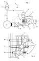
- the electric generator 2 has a field circuit 3 and a busbar 4 (stator three-phase circuit) connected to an electric grid 5 via a transformer 6.
- the static exciter 1 comprises a main transformer 8 having its high voltage side connected to the grid 5 (typically, as shown in the figures, the main transformer 8 is directly connected to the busbar 4 and is connected to the grid 5 via the transformer 6) and its low voltage side connected to a field circuit converter 9 (typically a rectifier).
- a field circuit converter 9 typically a rectifier
- the field circuit converter 9 converts the AC voltage from the main transformer 8 and feeds the generator field circuit 3 with a DC voltage.
- the static exciter 1 further comprises a control unit 11 arranged to detect the status of the grid 5 to cause at least a capacitor bank 13 to supply energy into the generator field circuit 3 in case the grid voltage falls below a prefixed voltage value.
- the capacitor bank 13 is connected between the low voltage side of the main transformer 8 and the AC side of the field circuit converter 9.
- the static exciter also comprises at least a coupling circuit 15 connecting the capacitor bank 13 to connection lines 16 between the low voltage side of the main transformer 8 and the AC side of the field circuit converter 9.
- the coupling circuit 15 comprises an auxiliary three-phase converter 17 having a DC side connected to the capacitor bank 13 and an AC side coupled to the connection lines 16.
- the auxiliary converter 17 is a bidirectional converter, such that charging and discharging of the capacitor bank 13 is allowed.
- the auxiliary converter 17 is made of a power semiconductor element bridge (IGBT, thristors); in any case these converters are well known in the art and any suitable converter or power semiconductor element disposition may be used to implement the present invention.
- IGBT power semiconductor element bridge
- thristors any suitable converter or power semiconductor element disposition may be used to implement the present invention.
- the AC side of the auxiliary converter 17 is inductively coupled to the connection lines 16 and, in this respect, the inductive coupling is realised via an auxiliary transformer 18.
- control unit 11 is connected to at least two auxiliary connection lines 19.
- auxiliary connection lines 19 may be provided and, in case of different configuration, (for example more or less than three phases) more or less than two connections may be provided.
- control unit 11 is connected to the auxiliary converter 17 to drive it.
- the control unit 11 detects the voltage of the auxiliary connection lines 19 between the auxiliary converter 17 and the auxiliary transformer 18 and drives the auxiliary converter 17 accordingly.
- control unit 11 drives the auxiliary converter 17 such that it lets the capacitor bank 13 be discharged or charged.
- the control unit 11 is also connected to the capacitor bank 13 to control its charging level.
- control unit 11 drives the auxiliary converter 17 such that it lets the electric power pass through it from the auxiliary transformer 18 to the capacitor bank 13.
- control unit 11 When the control unit 11 detects that the voltage at the auxiliary connection lines 19 has fallen below a prefixed voltage value, it drives the auxiliary converter 17 such that it allows the electric power to pass through it, from the capacitor bank 13 to the auxiliary transformer 18.
- the control unit 11 drives the auxiliary converter 17 such that it allows electric power to pass though it from the auxiliary transformer 18 to the capacitor bank 13 again.
- capacitor bank 13 is charged to be ready to intervene in case of further grid failures.
- Figure 2 shows a second embodiment of the static exciter of the invention.
- elements similar or equal to those already described with reference to the first embodiment have the same references.
- the static exciter in the second embodiment has the same structure and features of that of the first embodiment.
- this static exciter has three capacitor banks 13 each connected to an auxiliary single phase converter 17 connected to an auxiliary transformer 18 coupled to a connection line 16 between the main transformer 8 and the field circuit converter 9; moreover, a control unit 11 for each auxiliary converter 17 is provided or, alternatively, a single control unit 11 controlling independently each auxiliary converter 17 is provided (this embodiment is shown in figure 4 ).
- the static exciter has one electric power injection circuit for each phase (each electric power injection circuit comprising a capacitor bank 13, an auxiliary converter 17 and an auxiliary transformer 18), whereas the embodiment of figure 1 has only one three-phase electric power injection circuit.
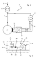
- FIGS 3 and 4 show a third embodiment of the static exciter 1 of the invention. Also in these figures, elements similar or equal to those already described have the same references.
- connection line 16 has a first branch 20 ( figure 4 ) with a first switch 21 and the coupling circuit 15 comprises a second branch 22 in parallel with the first branch 20.
- the second branch 22 has a second switch 23 in series with a one-way component 24; also the capacitor bank 13 is series with these components.
- the control unit 11 (also in this case a single control unit 11 for each connection line 16 or a single control unit 11 that independently controls the switches 21, 23 of each connection line 16) is connected to the respective connection line 16 and, in addition, drives the switches 21 and 23, i.e. it detects the voltage of the connection line 16 and operates the first and second switches 21, 23 accordingly.
- the one-way component 24 is a diode arranged to cause the capacitor bank 13 to supply energy to the field circuit 3 when it is discharged.
- a charging component 25 such as a battery or the like in parallel with the capacitor bank 13 may be provided.
- charging of the capacitor bank 13 may also be carried out during operation via the branch 22 (i.e. with switch 21 open and switch 23 closed) in case there is no fault at the grid 5 and the voltage at the connection lines 16 has its nominal value.
- the switch 21 is closed (dashed line in figure 4 ) whereas the switch 23 is open (dashed line in figure 4 ); therefore during normal operation the branch 20 is operative whereas the branch 22 is not operative.
- connection line 16 that is indicative of the voltage of the grid 5
- figure 4 shows in full line the configuration of the switch 21 and the switch 23 in case of failure with grid voltage drop; therefore in case of failure the branch 20 is not operative and the branch 22 is operative.
- the switch 23 When the switch 23 is closed, the capacitor bank 13 is discharged and the diode 24 forces the discharge direction, such that electric power is injected into the field circuit converter 9 and thus into the field circuit 3; the switch 21 (that is open) prevents the capacitor bank 13 from being short-circuited.
- the automatic security and protection systems restore the grid voltage in a short time.
- control unit 11 When the control unit 11 detects that the voltage at the connection line 16 is above the prefixed voltage value, it drives the switch 21 to close and the switch 23 to open.
- Closing of switch 21 and opening of switch 23 may also be carried out by the control unit 11 with a delay, such that the capacitor bank 13 is charged.
- the charging component 25 may charge the capacitor bank 13.
- the present invention also refers to a method for retrofitting a static exciter of an electric generator.
- the method comprises providing at least one capacitor bank 13 between the low voltage side of the main transformer 8 and the AC side of the field circuit converter 9.
- This retrofitting method is particularly advantageous because there is no need of modifying the rotor and, thus, there is no need of opening the generator casing and installing any component aboard of the rotor.
- the present invention also refers to a method for operating a static exciter of an electric generator.
- the capacitor bank 13 injects electric power between the low voltage side of the main transformer 8 and the AC side of the field circuit converter 9 when the grid voltage falls below a prefixed voltage value.
Priority Applications (3)
| Application Number | Priority Date | Filing Date | Title |
|---|---|---|---|
| EP09169645A EP2293432A1 (de) | 2009-09-07 | 2009-09-07 | Statischer Erreger eines elektrischen Generators, Verfahren zum Nachrüsten und Betriebsverfahren dafür |
| US12/861,253 US20110057631A1 (en) | 2009-09-07 | 2010-08-23 | Static exciter of an electric generator, method for retrofitting, and method for operating |
| CN201010286458XA CN102013866A (zh) | 2009-09-07 | 2010-09-07 | 发电机的静态励磁机、改型方法及其操作方法 |
Applications Claiming Priority (1)
| Application Number | Priority Date | Filing Date | Title |
|---|---|---|---|
| EP09169645A EP2293432A1 (de) | 2009-09-07 | 2009-09-07 | Statischer Erreger eines elektrischen Generators, Verfahren zum Nachrüsten und Betriebsverfahren dafür |
Publications (1)
| Publication Number | Publication Date |
|---|---|
| EP2293432A1 true EP2293432A1 (de) | 2011-03-09 |
Family
ID=41129135
Family Applications (1)
| Application Number | Title | Priority Date | Filing Date |
|---|---|---|---|
| EP09169645A Withdrawn EP2293432A1 (de) | 2009-09-07 | 2009-09-07 | Statischer Erreger eines elektrischen Generators, Verfahren zum Nachrüsten und Betriebsverfahren dafür |
Country Status (3)
| Country | Link |
|---|---|
| US (1) | US20110057631A1 (de) |
| EP (1) | EP2293432A1 (de) |
| CN (1) | CN102013866A (de) |
Cited By (3)
| Publication number | Priority date | Publication date | Assignee | Title |
|---|---|---|---|---|
| CN102412777A (zh) * | 2011-12-02 | 2012-04-11 | 华中科技大学 | 电流型三单相桥式变流器串联结构的自并励励磁控制系统 |
| EP2911292A1 (de) * | 2014-10-09 | 2015-08-26 | Alstom Technology Ltd | Verfahren und Generatorsystem zum Betrieb eines Generators |
| US9735719B2 (en) | 2014-05-12 | 2017-08-15 | General Electric Technology Gmbh | Static exciter system for generators |
Families Citing this family (10)
| Publication number | Priority date | Publication date | Assignee | Title |
|---|---|---|---|---|
| CN102386826A (zh) * | 2011-10-28 | 2012-03-21 | 华中科技大学 | 一种基于储能型动态电压恢复器的自并励励磁系统 |
| CN103023410A (zh) * | 2012-12-21 | 2013-04-03 | 重庆磐达机械有限公司 | 一种风冷发电机组的双励磁系统 |
| US9899942B2 (en) * | 2013-06-25 | 2018-02-20 | Siemens Energy, Inc. | Using static excitation system to reduce the amplitude of torsional oscillations due to fluctuating industrial loads |
| US9334749B2 (en) * | 2013-10-18 | 2016-05-10 | Abb Technology Ag | Auxiliary power system for turbine-based energy generation system |
| US9577557B2 (en) | 2013-10-18 | 2017-02-21 | Abb Schweiz Ag | Turbine-generator system with DC output |
| US9614457B2 (en) | 2013-10-18 | 2017-04-04 | Abb Schweiz Ag | Modular thyristor-based rectifier circuits |
| US9337762B1 (en) * | 2014-12-15 | 2016-05-10 | Eaton Corporation | System and method for magnetizing a transformer in an electrical system prior to energizing the electrical system |
| CN104836404A (zh) * | 2015-05-25 | 2015-08-12 | 湖南零陵恒远发电设备有限公司 | 一种双馈励磁机及其工作方法 |
| RU168545U1 (ru) * | 2016-07-20 | 2017-02-08 | Общество с ограниченной ответственностью Научно-производственное предприятие "ЭКРА" | Статический возбудитель синхронного двигателя |
| GB202117427D0 (en) * | 2021-12-02 | 2022-01-19 | Brush Elec Machines | An exciter circuit for a synchronous machine |
Citations (5)
| Publication number | Priority date | Publication date | Assignee | Title |
|---|---|---|---|---|
| US4426613A (en) * | 1983-03-23 | 1984-01-17 | Hokuetsu Industries Co., Ltd. | Control system for a self-excited alternating current generator |
| SU1312715A1 (ru) * | 1985-10-21 | 1987-05-23 | Днепродзержинский Индустриальный Институт Им.М.И.Арсеничева | Устройство дл управлени возбуждением синхронной машины |
| US5978242A (en) * | 1995-02-01 | 1999-11-02 | Fieldbus International A/S | AC/DC converter |
| EP0989667A1 (de) * | 1998-04-09 | 2000-03-29 | Mitsubishi Denki Kabushiki Kaisha | Vorrichtung zur Erregung eines Generators |
| US20070296275A1 (en) | 2004-10-28 | 2007-12-27 | Reinhard Joho | Static Exciter System for a Generator and Method of Operation |
Family Cites Families (14)
| Publication number | Priority date | Publication date | Assignee | Title |
|---|---|---|---|---|
| US3526823A (en) * | 1967-03-09 | 1970-09-01 | Gen Electric | Switching regulator control circuit |
| US3617857A (en) * | 1970-05-26 | 1971-11-02 | Motorola Inc | Voltage regulator for brushless alternator |
| US3908161A (en) * | 1974-02-07 | 1975-09-23 | Gen Electric | Field excitation system for synchronous machines utilizing a rotating transformer brushless exciter generating combination |
| CH571286A5 (de) * | 1974-02-07 | 1975-12-31 | Contraves Ag | |
| US4013937A (en) * | 1974-07-22 | 1977-03-22 | Westinghouse Electric Corporation | Naturally commutated cycloconverter with controlled input displacement power factor |
| US3959719A (en) * | 1975-04-30 | 1976-05-25 | General Electric Corporation | Static controller for power factor correction and adaptive filtering |
| US4129809A (en) * | 1977-04-28 | 1978-12-12 | Westinghouse Electric Corp. | Power factor corrected dual converter motor drive |
| US4210857A (en) * | 1978-04-19 | 1980-07-01 | Sheller-Globe Corporation | Field exerting and regulator circuit for a brushless alternator |
| JPS5534854A (en) * | 1978-09-04 | 1980-03-11 | Hitachi Ltd | Controlling method of secondary winding-exciting motor |
| US8134345B2 (en) * | 2005-11-29 | 2012-03-13 | General Electric Company | Cryogenic exciter |
| US7786620B2 (en) * | 2008-02-15 | 2010-08-31 | Honeywell International Inc. | Battery supplementing super capacitor energy storage charge and discharge converter |
| US20110194317A1 (en) * | 2008-08-22 | 2011-08-11 | Abb Inc. | Stacked flyback converter with independent current loop control |
| US20120228953A1 (en) * | 2008-09-27 | 2012-09-13 | Kesler Morris P | Tunable wireless energy transfer for furniture applications |
| US20120228954A1 (en) * | 2008-09-27 | 2012-09-13 | Kesler Morris P | Tunable wireless energy transfer for clothing applications |
-
2009
- 2009-09-07 EP EP09169645A patent/EP2293432A1/de not_active Withdrawn
-
2010
- 2010-08-23 US US12/861,253 patent/US20110057631A1/en not_active Abandoned
- 2010-09-07 CN CN201010286458XA patent/CN102013866A/zh active Pending
Patent Citations (5)
| Publication number | Priority date | Publication date | Assignee | Title |
|---|---|---|---|---|
| US4426613A (en) * | 1983-03-23 | 1984-01-17 | Hokuetsu Industries Co., Ltd. | Control system for a self-excited alternating current generator |
| SU1312715A1 (ru) * | 1985-10-21 | 1987-05-23 | Днепродзержинский Индустриальный Институт Им.М.И.Арсеничева | Устройство дл управлени возбуждением синхронной машины |
| US5978242A (en) * | 1995-02-01 | 1999-11-02 | Fieldbus International A/S | AC/DC converter |
| EP0989667A1 (de) * | 1998-04-09 | 2000-03-29 | Mitsubishi Denki Kabushiki Kaisha | Vorrichtung zur Erregung eines Generators |
| US20070296275A1 (en) | 2004-10-28 | 2007-12-27 | Reinhard Joho | Static Exciter System for a Generator and Method of Operation |
Cited By (6)
| Publication number | Priority date | Publication date | Assignee | Title |
|---|---|---|---|---|
| CN102412777A (zh) * | 2011-12-02 | 2012-04-11 | 华中科技大学 | 电流型三单相桥式变流器串联结构的自并励励磁控制系统 |
| CN102412777B (zh) * | 2011-12-02 | 2014-08-27 | 华中科技大学 | 电流型三单相桥式变流器串联结构的自并励励磁控制系统 |
| US9735719B2 (en) | 2014-05-12 | 2017-08-15 | General Electric Technology Gmbh | Static exciter system for generators |
| RU2682917C2 (ru) * | 2014-05-12 | 2019-03-22 | Дженерал Электрик Текнолоджи Гмбх | Система статического возбудителя для генераторов |
| EP2911292A1 (de) * | 2014-10-09 | 2015-08-26 | Alstom Technology Ltd | Verfahren und Generatorsystem zum Betrieb eines Generators |
| US9634595B2 (en) | 2014-10-09 | 2017-04-25 | General Electric Technology Gmbh | Method and a generator system for operating a generator |
Also Published As
| Publication number | Publication date |
|---|---|
| CN102013866A (zh) | 2011-04-13 |
| US20110057631A1 (en) | 2011-03-10 |
Similar Documents
| Publication | Publication Date | Title |
|---|---|---|
| EP2293432A1 (de) | Statischer Erreger eines elektrischen Generators, Verfahren zum Nachrüsten und Betriebsverfahren dafür | |
| KR101287596B1 (ko) | 교류 전력망에 태양광 발전 장비를 접속시키기 위한 방법 및 장치 | |
| US9543748B2 (en) | Fault protection system for a power system of dynamically positioned vessel | |
| KR100832769B1 (ko) | 이중 권선형 유도 발전기 시스템의 제어 및 보호 | |
| EP2667498A2 (de) | Fernlastbypasssystem | |
| KR101175576B1 (ko) | 발전기용 정적 여자기 시스템, 및 이러한 여자기 시스템의동작을 위한 방법 | |
| SE520333C2 (sv) | Elkraftsystem och metod för att kontrollera elkraft | |
| WO2016042601A1 (ja) | 風力発電システムおよび直流送電システム | |
| US20170373498A1 (en) | Distribution of electric energy on a vessel | |
| EP2566042B2 (de) | System und verfahren zur steuerung eines stromgenerators | |
| KR20030027022A (ko) | 풍력 설비 | |
| EP2288017B1 (de) | Statischer Erreger einer Feldwicklung und ein Verfahren, um diese zu betreiben | |
| CN109565275B (zh) | 配电系统和方法 | |
| CN111656659A (zh) | 用于逆变器装置的电容器放电的方法 | |
| EP2911292B1 (de) | Verfahren und Generatorsystem zum Betrieb eines Generators | |
| CN102804592A (zh) | 风能设备的叶片调整系统的紧急调整装置 | |
| JP6914358B2 (ja) | 分離システムの形成検出方法 | |
| Hunswadkar et al. | Considerations and methods for an effective fast bus transfer system | |
| EP2648301B1 (de) | Verfahren zum elektrischen Schutz einer Synchronmaschine und Stromerzeugungsanlage zur Versorgung eines elektrischen Netzwerks | |
| JP2023041179A (ja) | 無停電電源システム | |
| GEORGE | Comparison of Centralized and Decentralized Control While Achieving the Same Performance in the Operation of Microgrid | |
| JP2016096704A (ja) | 同期機の励磁装置、蓄電装置、および同期機の励磁方法 |
Legal Events
| Date | Code | Title | Description |
|---|---|---|---|
| PUAI | Public reference made under article 153(3) epc to a published international application that has entered the european phase |
Free format text: ORIGINAL CODE: 0009012 |
|
| AK | Designated contracting states |
Kind code of ref document: A1 Designated state(s): AT BE BG CH CY CZ DE DK EE ES FI FR GB GR HR HU IE IS IT LI LT LU LV MC MK MT NL NO PL PT RO SE SI SK SM TR |
|
| AX | Request for extension of the european patent |
Extension state: AL BA RS |
|
| 17P | Request for examination filed |
Effective date: 20110829 |
|
| 17Q | First examination report despatched |
Effective date: 20120113 |
|
| STAA | Information on the status of an ep patent application or granted ep patent |
Free format text: STATUS: THE APPLICATION IS DEEMED TO BE WITHDRAWN |
|
| 18D | Application deemed to be withdrawn |
Effective date: 20120724 |