EP2945235B1 - Tragbare schalttafel - Google Patents
Tragbare schalttafel Download PDFInfo
- Publication number
- EP2945235B1 EP2945235B1 EP15001335.7A EP15001335A EP2945235B1 EP 2945235 B1 EP2945235 B1 EP 2945235B1 EP 15001335 A EP15001335 A EP 15001335A EP 2945235 B1 EP2945235 B1 EP 2945235B1
- Authority
- EP
- European Patent Office
- Prior art keywords
- switchboard
- portions
- portable
- closed position
- pin
- Prior art date
- Legal status (The legal status is an assumption and is not a legal conclusion. Google has not performed a legal analysis and makes no representation as to the accuracy of the status listed.)
- Active
Links
- 238000010079 rubber tapping Methods 0.000 claims description 3
- 238000004804 winding Methods 0.000 claims description 2
- 241001492414 Marina Species 0.000 description 1
- 238000010276 construction Methods 0.000 description 1
- 230000005484 gravity Effects 0.000 description 1
- 230000004048 modification Effects 0.000 description 1
- 238000012986 modification Methods 0.000 description 1
Images


Classifications
-
- H—ELECTRICITY
- H02—GENERATION; CONVERSION OR DISTRIBUTION OF ELECTRIC POWER
- H02B—BOARDS, SUBSTATIONS OR SWITCHING ARRANGEMENTS FOR THE SUPPLY OR DISTRIBUTION OF ELECTRIC POWER
- H02B1/00—Frameworks, boards, panels, desks, casings; Details of substations or switching arrangements
- H02B1/26—Casings; Parts thereof or accessories therefor
- H02B1/52—Mobile units, e.g. for work sites
Definitions
- the present invention relates to a portable switchboard.
- Portable switchboards are commonly used in building yards and other venues where temporary electrical connections are required.
- Conventional portable switchboards are generally constituted by a casing that can hang on a wall or another support.
- a conventional portable switchboard is normally a parallelepiped with a main front side, on which the electrical sockets and the other required devices are arranged.
- the switchboard When installed at the building yard, the switchboard must hang from a support, typically a wall.
- US2005/0092356 discloses a portable power supply foldable around a hinge; it is in practice a solar cell module foldable for easy transport.
- US4318156 discloses a portable box for electrical power distribution in the form of a suitcase.
- the aim of the present invention is to provide a portable switchboard that is easier to transport and more versatile in use.
- an object of the invention is to provide a switchboard that is easier to carry by hand.
- Another object of the present invention is to provide a portable switchboard which, by virtue of its particular constructive characteristics, is capable of giving the greatest assurances of reliability and safety in use.
- a portable switchboard characterized in that it comprises at least two portions; each of said portions having a front side, on which electrical devices are arranged, and a substantially planar rear side; said portions being mutually hinged and defining at least two functional positions: a closed position, in which the respective rear sides of said portions face each other, and an open position, in which said rear sides of said portions substantially form a single continuous plane.
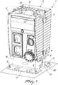
- the portable switchboard according to the invention globally designated by the reference numeral 1, has at least two portions, designated respectively by the reference numerals 2 and 3.
- Each portion has a front side and a rear side. Electrical devices, generally designated by the reference numeral 4, are arranged at the front side.
- the electrical devices are generally constituted by sockets, switches and any other required device.
- the rear side of each portion of the switchboard is substantially planar.
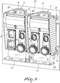
- the two portions 2 and 3 are hinged to one another and define at least two functional positions: a closed position, in which the rear sides of the two portions face each other, and an open position, in which the rear sides of the two portions form a substantially single continuous plane.
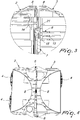
- the two portions are mutually hinged by means of hinges 5 and are provided with a means 6 for locking the portions in the closed position.
- hinges 5 and the locking means 6 are identical and their function is perfectly interchangeable.
- Each locking means or hinge includes a pin 7 adapted to slide in a first fixed part 13, associated with one of the portions 2 or 3, and adapted to engage a second fixed part 14, associated with the other portion.
- the pin 7 has an elastic lateral portion 15 and an elastic end portion 21.
- the elastic lateral portion 15 is adapted to retain the pin 7 in the first fixed part 13, as can be seen in Figure 3 , or in the second fixed part 14, when the pin is made to slide in it for the locking function or the hinge function.
- the elastic end portion 21 is used to open and close the switchboard. When the pin 7 is made to slide in the second fixed part 14, the elastic end portion 21 is compressed during closure.
- Each portion has an upper grip member 8.
- the grip members 8 are arranged side by side and constitute a handle that allows to carry the switchboard like a suitcase.
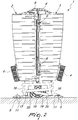
- Each portion has a base 11 that is blended with the body of the portion by means of an upright part 16.
- the upright parts 16 are used to wind the power supply cable 17, as shown in Figure 2 .
- the power supply cable 17 has a movable plug 18, which can be accommodated in an adapted cavity 19 formed between the upright parts 16 when the switchboard is in the closed position.
- the cavity 19 has a notch 20 that allows to insert the plug 18 in the cavity 19, after closing the switchboard and winding the cable 17, with an upward movement of the plug from below.
- the plug 18 does not exit merely by gravity, also because of the presence of the cable 17, and an intentional movement is required in order to make the plug exit from the cavity.
- the switchboard 1 In the closed position, the switchboard 1 is stable and can be simply rested on the ground and optionally fixed by means of expansion plugs 9 applied to adapted holes 10 provided in the base 11 of each portion 2, 3.
- the switchboard 1 can act as a power supply turret, of the type used in camping sites or marinas, and is useful in temporary applications, for example for public events, such as village fairs, concerts, etc., in which temporary power supply points are required.
- the switchboard 1 In the open position, the switchboard 1 can hang from a wall 12, like an ordinary building yard switchboard.
- the switchboard includes two upper holes 22 and two lower holes 23, on each portion.
- the holes 22 and 23 are adapted to receive fixing devices such as expansion plugs or self-tapping screws.
- the holes 22 and 23 allow to fasten the switchboard to a wall without the need to purchase accessories, for example brackets, but simply by using expansion plugs or self-tapping screws that are normally already present in the building yard.
- the invention achieves the intended aim and objects, providing a building yard switchboard which, by virtue of its construction in two hinged portions, can be closed and carried more easily than a traditional switchboard having a similar useful front surface.
- the switchboard in the closed position can rest on the ground and optionally be fixed with expansion plugs, and is perfectly functional.
- the materials used, as well as the dimensions, may of course be any according to the requirements and the state of the art.
Landscapes
- Engineering & Computer Science (AREA)
- Power Engineering (AREA)
- Patch Boards (AREA)
Claims (10)
- Eine tragbare Schalttafel, die mindestens zwei Abschnitte (2, 3) umfasst: wobei jeder der Abschnitte (2, 3) eine Vorderseite hat, an der elektrische Verrichtungen (4) angebracht sind, und eine im Wesentlichen flache Rückseite; wobei die Abschnitte (2, 3) gelenkig miteinander verbunden sind (5); wobei die tragbare Schalttafel dadurch gekennzeichnet ist, dass die Abschnitte (2, 3) mindestens zwei funktionelle Positionen bestimmten: eine geschlossene Position, in welcher die jeweiligen Rückseiten der Abschnitte (2, 3) einander zugewandt sind, und eine offene Position, in welcher die Rückseiten der Abschnitte (2, 3) im Wesentlichen eine einzige durchgehende Fläche bilden.
- Die tragbare Schalttafel gemäß Anspruch 1, dadurch gekennzeichnet, dass die Abschnitte (2, 3) durch Scharniere (5) gelenkig miteinander verbunden sind und ein Mittel (6) zum Verriegeln in der geschlossenen Position umfassen.
- Die tragbare Schalttafel gemäß Anspruch 1, dadurch gekennzeichnet, dass mindestens einer der Abschnitte (2, 3) ein oberes Greifglied (8) umfasst.
- Die tragbare Schalttafel gemäß Anspruch 1, dadurch gekennzeichnet, dass jeder der Abschnitte (2, 3) ein oberes Greifglied (8) hat; wobei in der geschlossenen Position die Greifglieder (8) nebeneinander angeordnet sind und einen Griff zum Tragen der Schalttafel (1) bilden.
- Die tragbare Schalttafel gemäß Anspruch 1, dadurch gekennzeichnet, dass jeder Abschnitt (2, 3) einen Fuß (11) hat, der mit Spitzen (10) für ein Mittel (9) zur Befestigung am Boden ausgestattet ist.
- Die tragbare Schalttafel gemäß Anspruch 1, dadurch gekennzeichnet, dass in der geschlossenen Position die Schalttafel (1) auf dem Boden abgestellt werden kann und sich im Betriebszustand befindet.
- Die tragbare Schalttafel gemäß Anspruch 1, dadurch gekennzeichnet, dass in der offenen Position die Schalttafel (1) an einer Wand angebracht werden kann und sich im Betriebszustand befindet.
- Die tragbare Schalttafel gemäß Anspruch 2, dadurch gekennzeichnet, dass jedes der Verriegelungsmittel (6) und jedes der Scharniere (5) einen Stift (7) umfasst, der ausgebildet ist, um in einem ersten festen Teil (13) zu gleiten, das mit einem der Abschnitte (2, 3) verbunden ist, und ausgebildet, um in einen zweiten festen Teil (14) einzugreifen, der mit dem anderen der Abschnitte (2, 3) verbunden ist; wobei der Stift (7) einen elastischen Seitenabschnitt (15) und einen elastischen Endabschnitt (21) umfasst; wobei der elastische Seitenabschnitt (15) den Stift (7) in dem ersten festen Teil (13) oder in dem zweiten festen Teil (14) hält, wenn der Stift (7) darin zum Zwecke der Verriegelungsfunktion und zum Zwecke der Scharnierfunktion zum Gleiten gebracht wird; wobei der elastische Endabschnitt (21) genutzt wird, um die Schalttafel (1) zu öffnen und zu schließen; wenn der Stift (7) veranlasst wird, in den zweiten festen Teil (14) zu gleiten, wird der elastische Endabschnitt (21) während des Schließens zusammengedrückt; um die Schalttafel (1) zu öffnen, genügt es, die Öffnungsbewegung zu erzwingen, bis der elastische Endabschnitt (21) nachgibt und ausreichend verformt wird, um die Bewegung des Stifts (7) zu ermöglichen.
- Die tragbare Schalttafel gemäß einem oder mehreren der obigen Ansprüche, dadurch gekennzeichnet, dass jeder der Abschnitte (2, 3) einen Fuß (11) umfasst, der mit einem aufrecht stehenden Teil (16) in den Körper des Abschnitts (2, 3) übergeht; wobei in der geschlossenen Position die aufrecht stehenden Teile (16) verwendet werden, um ein Stromversorgungskabel (17) aufzuwickeln; wobei das Stromversorgungskabel (17) einen beweglichen Stecker (18) hat, welcher in einen Hohlraum (19) aufgenommen werden kann, der zwischen den aufrecht stehenden Teilen (16) geformt ist, wenn sich die Schalttafel (1) in der geschlossenen Position befindet; wobei der Hohlraum (19) eine Kerbe (20) hat, die es ermöglicht, den Stecker (18) nach Schließen der Schalttafel (1) und Aufwickeln des Kabels (17) in den Hohlraum (19) einzuführen.
- Die tragbare Schalttafel gemäß einem oder mehreren der obigen Ansprüche, dadurch gekennzeichnet, dass jeder Abschnitt (2, 3) zwei obere Bohrungen (22) und zwei untere Bohrungen (23) umfasst, ausgebildet, um Befestigungsvorrichtungen, wie zum Beispiel Ausdehnungszapfen und Schneidschrauben, aufzunehmen.
Applications Claiming Priority (1)
| Application Number | Priority Date | Filing Date | Title |
|---|---|---|---|
| ITMI20140872 | 2014-05-13 |
Publications (2)
| Publication Number | Publication Date |
|---|---|
| EP2945235A1 EP2945235A1 (de) | 2015-11-18 |
| EP2945235B1 true EP2945235B1 (de) | 2017-08-09 |
Family
ID=51179020
Family Applications (1)
| Application Number | Title | Priority Date | Filing Date |
|---|---|---|---|
| EP15001335.7A Active EP2945235B1 (de) | 2014-05-13 | 2015-05-06 | Tragbare schalttafel |
Country Status (1)
| Country | Link |
|---|---|
| EP (1) | EP2945235B1 (de) |
Family Cites Families (2)
| Publication number | Priority date | Publication date | Assignee | Title |
|---|---|---|---|---|
| US4318156A (en) | 1980-04-30 | 1982-03-02 | Gallagher Michael J | Portable distribution box |
| JP3830935B2 (ja) | 2003-10-29 | 2006-10-11 | シャープ株式会社 | 携帯型電源 |
-
2015
- 2015-05-06 EP EP15001335.7A patent/EP2945235B1/de active Active
Non-Patent Citations (1)
| Title |
|---|
| None * |
Also Published As
| Publication number | Publication date |
|---|---|
| EP2945235A1 (de) | 2015-11-18 |
Similar Documents
| Publication | Publication Date | Title |
|---|---|---|
| US8975863B2 (en) | Charging station for use in charging electrically powered vehicles | |
| GB2565413A (en) | Attachment member and lock having the same | |
| USD537785S1 (en) | Retractable and interchangeable access panel for electronic or like devices | |
| FR3014608B1 (fr) | Cadre de montage pour l'encastrement d'une boite electrique dans une paroi et ensemble comprenant un tel cadre de montage et une boite electrique | |
| WO2020208371A1 (en) | Modular power supply system including a battery power supply module | |
| EP2945235B1 (de) | Tragbare schalttafel | |
| KR20170002401U (ko) | 배전반 함체 도어 고정장치 | |
| CN103493318A (zh) | 用于开关柜的铰链组件 | |
| KR20160026384A (ko) | 분실 방지용 다목적 충전기 | |
| KR101222448B1 (ko) | 태양전지판이 구비된 이동 통신기기용 충전장치 | |
| CN102801034B (zh) | 地面电源插座盖组件 | |
| USD798687S1 (en) | Hinge lock | |
| US20170152877A1 (en) | System for Safely Assembling Washing Machines for Vehicles | |
| KR102307117B1 (ko) | 이동식 소형 가건물 | |
| CN106255435B (zh) | 便携式酒吧柜台 | |
| JP2008208637A (ja) | 建具及びその建具の配線方法 | |
| CN203515204U (zh) | 折叠门 | |
| AU2018100283A4 (en) | An enclosure for a switchboard | |
| KR101020575B1 (ko) | 벽면매설용 공동주택용 콘센트박스 | |
| JP2017169359A (ja) | 間接活線工具の収納体用のフレーム構造 | |
| KR101672005B1 (ko) | 핸드레일 | |
| JP6808556B2 (ja) | 物品載置棚装置 | |
| AU2016102388A4 (en) | Connecting element, box part and assembly kit for forming a box that is to be built into a wall recess | |
| CN204858330U (zh) | 一种方便检修的室内配电箱 | |
| CN208132914U (zh) | 工具箱 |
Legal Events
| Date | Code | Title | Description |
|---|---|---|---|
| PUAI | Public reference made under article 153(3) epc to a published international application that has entered the european phase |
Free format text: ORIGINAL CODE: 0009012 |
|
| AK | Designated contracting states |
Kind code of ref document: A1 Designated state(s): AL AT BE BG CH CY CZ DE DK EE ES FI FR GB GR HR HU IE IS IT LI LT LU LV MC MK MT NL NO PL PT RO RS SE SI SK SM TR |
|
| AX | Request for extension of the european patent |
Extension state: BA ME |
|
| RBV | Designated contracting states (corrected) |
Designated state(s): AL AT BE BG CH CY CZ DE DK EE ES FI FR GB GR HR HU IE IS IT LI LT LU LV MC MK MT NL NO PL PT RO RS SE SI SK SM TR |
|
| 17P | Request for examination filed |
Effective date: 20160310 |
|
| 17Q | First examination report despatched |
Effective date: 20160504 |
|
| GRAP | Despatch of communication of intention to grant a patent |
Free format text: ORIGINAL CODE: EPIDOSNIGR1 |
|
| INTG | Intention to grant announced |
Effective date: 20170329 |
|
| GRAS | Grant fee paid |
Free format text: ORIGINAL CODE: EPIDOSNIGR3 |
|
| GRAA | (expected) grant |
Free format text: ORIGINAL CODE: 0009210 |
|
| AK | Designated contracting states |
Kind code of ref document: B1 Designated state(s): AL AT BE BG CH CY CZ DE DK EE ES FI FR GB GR HR HU IE IS IT LI LT LU LV MC MK MT NL NO PL PT RO RS SE SI SK SM TR |
|
| REG | Reference to a national code |
Ref country code: GB Ref legal event code: FG4D |
|
| REG | Reference to a national code |
Ref country code: CH Ref legal event code: EP Ref country code: AT Ref legal event code: REF Ref document number: 917790 Country of ref document: AT Kind code of ref document: T Effective date: 20170815 |
|
| REG | Reference to a national code |
Ref country code: IE Ref legal event code: FG4D |
|
| REG | Reference to a national code |
Ref country code: DE Ref legal event code: R096 Ref document number: 602015003918 Country of ref document: DE |
|
| REG | Reference to a national code |
Ref country code: NL Ref legal event code: MP Effective date: 20170809 |
|
| REG | Reference to a national code |
Ref country code: LT Ref legal event code: MG4D |
|
| REG | Reference to a national code |
Ref country code: AT Ref legal event code: MK05 Ref document number: 917790 Country of ref document: AT Kind code of ref document: T Effective date: 20170809 |
|
| PG25 | Lapsed in a contracting state [announced via postgrant information from national office to epo] |
Ref country code: AT Free format text: LAPSE BECAUSE OF FAILURE TO SUBMIT A TRANSLATION OF THE DESCRIPTION OR TO PAY THE FEE WITHIN THE PRESCRIBED TIME-LIMIT Effective date: 20170809 Ref country code: FI Free format text: LAPSE BECAUSE OF FAILURE TO SUBMIT A TRANSLATION OF THE DESCRIPTION OR TO PAY THE FEE WITHIN THE PRESCRIBED TIME-LIMIT Effective date: 20170809 Ref country code: NO Free format text: LAPSE BECAUSE OF FAILURE TO SUBMIT A TRANSLATION OF THE DESCRIPTION OR TO PAY THE FEE WITHIN THE PRESCRIBED TIME-LIMIT Effective date: 20171109 Ref country code: LT Free format text: LAPSE BECAUSE OF FAILURE TO SUBMIT A TRANSLATION OF THE DESCRIPTION OR TO PAY THE FEE WITHIN THE PRESCRIBED TIME-LIMIT Effective date: 20170809 Ref country code: SE Free format text: LAPSE BECAUSE OF FAILURE TO SUBMIT A TRANSLATION OF THE DESCRIPTION OR TO PAY THE FEE WITHIN THE PRESCRIBED TIME-LIMIT Effective date: 20170809 Ref country code: NL Free format text: LAPSE BECAUSE OF FAILURE TO SUBMIT A TRANSLATION OF THE DESCRIPTION OR TO PAY THE FEE WITHIN THE PRESCRIBED TIME-LIMIT Effective date: 20170809 Ref country code: HR Free format text: LAPSE BECAUSE OF FAILURE TO SUBMIT A TRANSLATION OF THE DESCRIPTION OR TO PAY THE FEE WITHIN THE PRESCRIBED TIME-LIMIT Effective date: 20170809 |
|
| PG25 | Lapsed in a contracting state [announced via postgrant information from national office to epo] |
Ref country code: ES Free format text: LAPSE BECAUSE OF FAILURE TO SUBMIT A TRANSLATION OF THE DESCRIPTION OR TO PAY THE FEE WITHIN THE PRESCRIBED TIME-LIMIT Effective date: 20170809 Ref country code: RS Free format text: LAPSE BECAUSE OF FAILURE TO SUBMIT A TRANSLATION OF THE DESCRIPTION OR TO PAY THE FEE WITHIN THE PRESCRIBED TIME-LIMIT Effective date: 20170809 Ref country code: IS Free format text: LAPSE BECAUSE OF FAILURE TO SUBMIT A TRANSLATION OF THE DESCRIPTION OR TO PAY THE FEE WITHIN THE PRESCRIBED TIME-LIMIT Effective date: 20171209 Ref country code: BG Free format text: LAPSE BECAUSE OF FAILURE TO SUBMIT A TRANSLATION OF THE DESCRIPTION OR TO PAY THE FEE WITHIN THE PRESCRIBED TIME-LIMIT Effective date: 20171109 Ref country code: LV Free format text: LAPSE BECAUSE OF FAILURE TO SUBMIT A TRANSLATION OF THE DESCRIPTION OR TO PAY THE FEE WITHIN THE PRESCRIBED TIME-LIMIT Effective date: 20170809 Ref country code: GR Free format text: LAPSE BECAUSE OF FAILURE TO SUBMIT A TRANSLATION OF THE DESCRIPTION OR TO PAY THE FEE WITHIN THE PRESCRIBED TIME-LIMIT Effective date: 20171110 Ref country code: PL Free format text: LAPSE BECAUSE OF FAILURE TO SUBMIT A TRANSLATION OF THE DESCRIPTION OR TO PAY THE FEE WITHIN THE PRESCRIBED TIME-LIMIT Effective date: 20170809 |
|
| PG25 | Lapsed in a contracting state [announced via postgrant information from national office to epo] |
Ref country code: DK Free format text: LAPSE BECAUSE OF FAILURE TO SUBMIT A TRANSLATION OF THE DESCRIPTION OR TO PAY THE FEE WITHIN THE PRESCRIBED TIME-LIMIT Effective date: 20170809 Ref country code: CZ Free format text: LAPSE BECAUSE OF FAILURE TO SUBMIT A TRANSLATION OF THE DESCRIPTION OR TO PAY THE FEE WITHIN THE PRESCRIBED TIME-LIMIT Effective date: 20170809 Ref country code: RO Free format text: LAPSE BECAUSE OF FAILURE TO SUBMIT A TRANSLATION OF THE DESCRIPTION OR TO PAY THE FEE WITHIN THE PRESCRIBED TIME-LIMIT Effective date: 20170809 |
|
| REG | Reference to a national code |
Ref country code: FR Ref legal event code: PLFP Year of fee payment: 4 |
|
| REG | Reference to a national code |
Ref country code: DE Ref legal event code: R097 Ref document number: 602015003918 Country of ref document: DE |
|
| PG25 | Lapsed in a contracting state [announced via postgrant information from national office to epo] |
Ref country code: EE Free format text: LAPSE BECAUSE OF FAILURE TO SUBMIT A TRANSLATION OF THE DESCRIPTION OR TO PAY THE FEE WITHIN THE PRESCRIBED TIME-LIMIT Effective date: 20170809 Ref country code: SK Free format text: LAPSE BECAUSE OF FAILURE TO SUBMIT A TRANSLATION OF THE DESCRIPTION OR TO PAY THE FEE WITHIN THE PRESCRIBED TIME-LIMIT Effective date: 20170809 Ref country code: SM Free format text: LAPSE BECAUSE OF FAILURE TO SUBMIT A TRANSLATION OF THE DESCRIPTION OR TO PAY THE FEE WITHIN THE PRESCRIBED TIME-LIMIT Effective date: 20170809 |
|
| PLBE | No opposition filed within time limit |
Free format text: ORIGINAL CODE: 0009261 |
|
| STAA | Information on the status of an ep patent application or granted ep patent |
Free format text: STATUS: NO OPPOSITION FILED WITHIN TIME LIMIT |
|
| 26N | No opposition filed |
Effective date: 20180511 |
|
| PG25 | Lapsed in a contracting state [announced via postgrant information from national office to epo] |
Ref country code: SI Free format text: LAPSE BECAUSE OF FAILURE TO SUBMIT A TRANSLATION OF THE DESCRIPTION OR TO PAY THE FEE WITHIN THE PRESCRIBED TIME-LIMIT Effective date: 20170809 |
|
| REG | Reference to a national code |
Ref country code: CH Ref legal event code: PL |
|
| REG | Reference to a national code |
Ref country code: BE Ref legal event code: MM Effective date: 20180531 |
|
| PG25 | Lapsed in a contracting state [announced via postgrant information from national office to epo] |
Ref country code: MC Free format text: LAPSE BECAUSE OF FAILURE TO SUBMIT A TRANSLATION OF THE DESCRIPTION OR TO PAY THE FEE WITHIN THE PRESCRIBED TIME-LIMIT Effective date: 20170809 |
|
| REG | Reference to a national code |
Ref country code: IE Ref legal event code: MM4A |
|
| PG25 | Lapsed in a contracting state [announced via postgrant information from national office to epo] |
Ref country code: CH Free format text: LAPSE BECAUSE OF NON-PAYMENT OF DUE FEES Effective date: 20180531 Ref country code: LI Free format text: LAPSE BECAUSE OF NON-PAYMENT OF DUE FEES Effective date: 20180531 |
|
| PG25 | Lapsed in a contracting state [announced via postgrant information from national office to epo] |
Ref country code: LU Free format text: LAPSE BECAUSE OF NON-PAYMENT OF DUE FEES Effective date: 20180506 |
|
| PG25 | Lapsed in a contracting state [announced via postgrant information from national office to epo] |
Ref country code: IE Free format text: LAPSE BECAUSE OF NON-PAYMENT OF DUE FEES Effective date: 20180506 |
|
| PG25 | Lapsed in a contracting state [announced via postgrant information from national office to epo] |
Ref country code: BE Free format text: LAPSE BECAUSE OF NON-PAYMENT OF DUE FEES Effective date: 20180531 |
|
| PG25 | Lapsed in a contracting state [announced via postgrant information from national office to epo] |
Ref country code: MT Free format text: LAPSE BECAUSE OF NON-PAYMENT OF DUE FEES Effective date: 20180506 |
|
| PG25 | Lapsed in a contracting state [announced via postgrant information from national office to epo] |
Ref country code: TR Free format text: LAPSE BECAUSE OF FAILURE TO SUBMIT A TRANSLATION OF THE DESCRIPTION OR TO PAY THE FEE WITHIN THE PRESCRIBED TIME-LIMIT Effective date: 20170809 |
|
| PG25 | Lapsed in a contracting state [announced via postgrant information from national office to epo] |
Ref country code: PT Free format text: LAPSE BECAUSE OF FAILURE TO SUBMIT A TRANSLATION OF THE DESCRIPTION OR TO PAY THE FEE WITHIN THE PRESCRIBED TIME-LIMIT Effective date: 20170809 |
|
| PG25 | Lapsed in a contracting state [announced via postgrant information from national office to epo] |
Ref country code: HU Free format text: LAPSE BECAUSE OF FAILURE TO SUBMIT A TRANSLATION OF THE DESCRIPTION OR TO PAY THE FEE WITHIN THE PRESCRIBED TIME-LIMIT; INVALID AB INITIO Effective date: 20150506 Ref country code: MK Free format text: LAPSE BECAUSE OF NON-PAYMENT OF DUE FEES Effective date: 20170809 Ref country code: CY Free format text: LAPSE BECAUSE OF FAILURE TO SUBMIT A TRANSLATION OF THE DESCRIPTION OR TO PAY THE FEE WITHIN THE PRESCRIBED TIME-LIMIT Effective date: 20170809 |
|
| PG25 | Lapsed in a contracting state [announced via postgrant information from national office to epo] |
Ref country code: AL Free format text: LAPSE BECAUSE OF FAILURE TO SUBMIT A TRANSLATION OF THE DESCRIPTION OR TO PAY THE FEE WITHIN THE PRESCRIBED TIME-LIMIT Effective date: 20170809 |
|
| PGFP | Annual fee paid to national office [announced via postgrant information from national office to epo] |
Ref country code: FR Payment date: 20230322 Year of fee payment: 9 |
|
| PGFP | Annual fee paid to national office [announced via postgrant information from national office to epo] |
Ref country code: IT Payment date: 20230223 Year of fee payment: 9 |
|
| P01 | Opt-out of the competence of the unified patent court (upc) registered |
Effective date: 20230526 |
|
| PGFP | Annual fee paid to national office [announced via postgrant information from national office to epo] |
Ref country code: DE Payment date: 20230515 Year of fee payment: 9 |
|
| PGFP | Annual fee paid to national office [announced via postgrant information from national office to epo] |
Ref country code: GB Payment date: 20240318 Year of fee payment: 10 |