EP2944525B1 - Elektrisches bremssystem - Google Patents
Elektrisches bremssystem Download PDFInfo
- Publication number
- EP2944525B1 EP2944525B1 EP14738019.0A EP14738019A EP2944525B1 EP 2944525 B1 EP2944525 B1 EP 2944525B1 EP 14738019 A EP14738019 A EP 14738019A EP 2944525 B1 EP2944525 B1 EP 2944525B1
- Authority
- EP
- European Patent Office
- Prior art keywords
- brake
- vehicle
- load
- vehicle speed
- detecting means
- Prior art date
- Legal status (The legal status is an assumption and is not a legal conclusion. Google has not performed a legal analysis and makes no representation as to the accuracy of the status listed.)
- Not-in-force
Links
- 230000007246 mechanism Effects 0.000 claims description 46
- 238000001514 detection method Methods 0.000 claims description 15
- 230000008859 change Effects 0.000 claims description 10
- 230000001133 acceleration Effects 0.000 claims description 9
- 238000006243 chemical reaction Methods 0.000 description 11
- 230000000881 depressing effect Effects 0.000 description 7
- 230000000994 depressogenic effect Effects 0.000 description 7
- 125000006850 spacer group Chemical group 0.000 description 6
- 230000002093 peripheral effect Effects 0.000 description 3
- 238000005096 rolling process Methods 0.000 description 3
- XEEYBQQBJWHFJM-UHFFFAOYSA-N Iron Chemical compound [Fe] XEEYBQQBJWHFJM-UHFFFAOYSA-N 0.000 description 2
- 238000010586 diagram Methods 0.000 description 2
- 230000004323 axial length Effects 0.000 description 1
- 230000008878 coupling Effects 0.000 description 1
- 238000010168 coupling process Methods 0.000 description 1
- 238000005859 coupling reaction Methods 0.000 description 1
- 230000003247 decreasing effect Effects 0.000 description 1
- 229910052742 iron Inorganic materials 0.000 description 1
- 239000000696 magnetic material Substances 0.000 description 1
- 230000009467 reduction Effects 0.000 description 1
- 239000000725 suspension Substances 0.000 description 1
Images





Classifications
-
- B—PERFORMING OPERATIONS; TRANSPORTING
- B60—VEHICLES IN GENERAL
- B60T—VEHICLE BRAKE CONTROL SYSTEMS OR PARTS THEREOF; BRAKE CONTROL SYSTEMS OR PARTS THEREOF, IN GENERAL; ARRANGEMENT OF BRAKING ELEMENTS ON VEHICLES IN GENERAL; PORTABLE DEVICES FOR PREVENTING UNWANTED MOVEMENT OF VEHICLES; VEHICLE MODIFICATIONS TO FACILITATE COOLING OF BRAKES
- B60T8/00—Arrangements for adjusting wheel-braking force to meet varying vehicular or ground-surface conditions, e.g. limiting or varying distribution of braking force
- B60T8/17—Using electrical or electronic regulation means to control braking
-
- B—PERFORMING OPERATIONS; TRANSPORTING
- B60—VEHICLES IN GENERAL
- B60T—VEHICLE BRAKE CONTROL SYSTEMS OR PARTS THEREOF; BRAKE CONTROL SYSTEMS OR PARTS THEREOF, IN GENERAL; ARRANGEMENT OF BRAKING ELEMENTS ON VEHICLES IN GENERAL; PORTABLE DEVICES FOR PREVENTING UNWANTED MOVEMENT OF VEHICLES; VEHICLE MODIFICATIONS TO FACILITATE COOLING OF BRAKES
- B60T7/00—Brake-action initiating means
- B60T7/02—Brake-action initiating means for personal initiation
- B60T7/04—Brake-action initiating means for personal initiation foot actuated
- B60T7/042—Brake-action initiating means for personal initiation foot actuated by electrical means, e.g. using travel or force sensors
-
- B—PERFORMING OPERATIONS; TRANSPORTING
- B60—VEHICLES IN GENERAL
- B60T—VEHICLE BRAKE CONTROL SYSTEMS OR PARTS THEREOF; BRAKE CONTROL SYSTEMS OR PARTS THEREOF, IN GENERAL; ARRANGEMENT OF BRAKING ELEMENTS ON VEHICLES IN GENERAL; PORTABLE DEVICES FOR PREVENTING UNWANTED MOVEMENT OF VEHICLES; VEHICLE MODIFICATIONS TO FACILITATE COOLING OF BRAKES
- B60T13/00—Transmitting braking action from initiating means to ultimate brake actuator with power assistance or drive; Brake systems incorporating such transmitting means, e.g. air-pressure brake systems
- B60T13/74—Transmitting braking action from initiating means to ultimate brake actuator with power assistance or drive; Brake systems incorporating such transmitting means, e.g. air-pressure brake systems with electrical assistance or drive
- B60T13/741—Transmitting braking action from initiating means to ultimate brake actuator with power assistance or drive; Brake systems incorporating such transmitting means, e.g. air-pressure brake systems with electrical assistance or drive acting on an ultimate actuator
-
- B—PERFORMING OPERATIONS; TRANSPORTING
- B60—VEHICLES IN GENERAL
- B60T—VEHICLE BRAKE CONTROL SYSTEMS OR PARTS THEREOF; BRAKE CONTROL SYSTEMS OR PARTS THEREOF, IN GENERAL; ARRANGEMENT OF BRAKING ELEMENTS ON VEHICLES IN GENERAL; PORTABLE DEVICES FOR PREVENTING UNWANTED MOVEMENT OF VEHICLES; VEHICLE MODIFICATIONS TO FACILITATE COOLING OF BRAKES
- B60T7/00—Brake-action initiating means
- B60T7/02—Brake-action initiating means for personal initiation
- B60T7/04—Brake-action initiating means for personal initiation foot actuated
-
- F—MECHANICAL ENGINEERING; LIGHTING; HEATING; WEAPONS; BLASTING
- F16—ENGINEERING ELEMENTS AND UNITS; GENERAL MEASURES FOR PRODUCING AND MAINTAINING EFFECTIVE FUNCTIONING OF MACHINES OR INSTALLATIONS; THERMAL INSULATION IN GENERAL
- F16D—COUPLINGS FOR TRANSMITTING ROTATION; CLUTCHES; BRAKES
- F16D65/00—Parts or details
- F16D65/14—Actuating mechanisms for brakes; Means for initiating operation at a predetermined position
- F16D65/16—Actuating mechanisms for brakes; Means for initiating operation at a predetermined position arranged in or on the brake
- F16D65/18—Actuating mechanisms for brakes; Means for initiating operation at a predetermined position arranged in or on the brake adapted for drawing members together, e.g. for disc brakes
-
- F—MECHANICAL ENGINEERING; LIGHTING; HEATING; WEAPONS; BLASTING
- F16—ENGINEERING ELEMENTS AND UNITS; GENERAL MEASURES FOR PRODUCING AND MAINTAINING EFFECTIVE FUNCTIONING OF MACHINES OR INSTALLATIONS; THERMAL INSULATION IN GENERAL
- F16D—COUPLINGS FOR TRANSMITTING ROTATION; CLUTCHES; BRAKES
- F16D2121/00—Type of actuator operation force
- F16D2121/18—Electric or magnetic
- F16D2121/24—Electric or magnetic using motors
-
- F—MECHANICAL ENGINEERING; LIGHTING; HEATING; WEAPONS; BLASTING
- F16—ENGINEERING ELEMENTS AND UNITS; GENERAL MEASURES FOR PRODUCING AND MAINTAINING EFFECTIVE FUNCTIONING OF MACHINES OR INSTALLATIONS; THERMAL INSULATION IN GENERAL
- F16D—COUPLINGS FOR TRANSMITTING ROTATION; CLUTCHES; BRAKES
- F16D2125/00—Components of actuators
- F16D2125/18—Mechanical mechanisms
- F16D2125/20—Mechanical mechanisms converting rotation to linear movement or vice versa
- F16D2125/34—Mechanical mechanisms converting rotation to linear movement or vice versa acting in the direction of the axis of rotation
- F16D2125/40—Screw-and-nut
-
- F—MECHANICAL ENGINEERING; LIGHTING; HEATING; WEAPONS; BLASTING
- F16—ENGINEERING ELEMENTS AND UNITS; GENERAL MEASURES FOR PRODUCING AND MAINTAINING EFFECTIVE FUNCTIONING OF MACHINES OR INSTALLATIONS; THERMAL INSULATION IN GENERAL
- F16D—COUPLINGS FOR TRANSMITTING ROTATION; CLUTCHES; BRAKES
- F16D2125/00—Components of actuators
- F16D2125/18—Mechanical mechanisms
- F16D2125/44—Mechanical mechanisms transmitting rotation
- F16D2125/46—Rotating members in mutual engagement
- F16D2125/48—Rotating members in mutual engagement with parallel stationary axes, e.g. spur gears
-
- F—MECHANICAL ENGINEERING; LIGHTING; HEATING; WEAPONS; BLASTING
- F16—ENGINEERING ELEMENTS AND UNITS; GENERAL MEASURES FOR PRODUCING AND MAINTAINING EFFECTIVE FUNCTIONING OF MACHINES OR INSTALLATIONS; THERMAL INSULATION IN GENERAL
- F16D—COUPLINGS FOR TRANSMITTING ROTATION; CLUTCHES; BRAKES
- F16D2125/00—Components of actuators
- F16D2125/18—Mechanical mechanisms
- F16D2125/44—Mechanical mechanisms transmitting rotation
- F16D2125/46—Rotating members in mutual engagement
- F16D2125/50—Rotating members in mutual engagement with parallel non-stationary axes, e.g. planetary gearing
Definitions
- This invention relates to an electric brake system which consumes less electric power.
- Electric brakes of the type in which a friction pad is pressed against a brake disk by an electric motor to apply a brake are disclosed e.g. in the below-identified Patent documents 1 and 2.
- These electric brakes include a linear motion mechanism for converting the rotation of the electric motor to a linear motion.
- the linear motion mechanism includes e.g. a ball-screw mechanism (as disclosed in Patent document 1) or a planetary reduction gear mechanism (as disclosed in Patent document 2).
- the magnetic load sensor 24 includes a load detection sensor in the form of a magnetic load sensor 24.
- the magnetic load sensor 24 includes a flange member 40 and a support member 41 which are in the form of annular plates and axially spaced apart from and axially face each other, a magnetic target 42 which generates a magnetic field, and a magnetic sensor element 43 capable of detecting a magnetic field.
- the support member 41 is mounted on a rotary shaft 20 at a position axially rearwardly of the flange member 40.
- the magnetic sensor element 43 and the magnetic target 42 face each other in a direction perpendicular to the rotary shaft 20.
- the electric motor 1 is actuated to control the braking force such that the difference between the above detected value and the target value (amount of depression of the brake pedal) is zero.
- the document FR 2 835 896 A1 discloses an electric brake system comprising an electric bake including a rotary shaft configured to be driven by an electric motor, a friction pad, a linear motion mechanism configured to convert a rotation of the rotary shaft to a linear motion of the friction pad, thereby pressing the friction pad against a brake disk, and a control means configured to receive a detection output of a detecting means for detecting a contact of the friction pad applied to the brake disk, and a detection output of a vehicle speed detecting means for detecting a vehicle speed, and to control the electric motor based on the outputs received.
- the document EP 2 444 293 A2 discloses a vehicle creep device where a dead band of a brake pedal is provided.
- the electric motor is actuated to reduce the difference between the target value corresponding to the brake operation and the detected value of the load detecting sensor to zero, in spite of the fact that the vehicle is at a stop. Since the output of the electric motor is given by "the number of revolutions multiplied by the torque", electric power is consumed, which deteriorates energy efficiency.
- An object of the present invention is to prevent an increase in power consumption even if unnecessary brake operations are carried out.
- the present invention provides an electric brake system comprising an electric brake including a rotary shaft configured to be driven by an electric motor, a friction pad, a linear motion mechanism configured to convert the rotation of the rotary shaft to a liner motion of the friction pad, thereby pressing the friction pad against the brake disk, and a control means configured to receive a detection output of a load detecting means for detecting the intensity of a load applied to the brake disk, a brake load command output from a brake pedal, and a detection output of a vehicle speed detecting means for detecting the vehicle speed, and to control the electric motor based on the outputs received, wherein the control means is provided with a dead band within which a brake load applied by the linear motion mechanism does not change even if the load command output from the brake pedal is deviated from the detection output of the load detecting means, when it is detected that the vehicle is at a stop based on the detection signal of the vehicle speed detecting means.
- the load command output from the brake pedal is compared with the detected load output of the load detecting means while the vehicle is at a stop, and even if the former is deviated from the latter, if the difference therebetween is within the dead band, the braking load is not changed when the brake pedal is operated.
- Another dead band may be provided to be used while the vehicle is traveling such that this dead band has a width narrower than the dead band to be used while the vehicle is at a stop.
- the dead band to be used while the vehicle is traveling has a width narrower than the dead band to be used while the vehicle is at a stop.
- a timer means may be further provided for detecting the time period during which the vehicle is at a stop such that the width of the dead band is changed based on the time period during which the vehicle is at a stop.
- the vehicle speed detecting means may be wheel speed sensors provided at the vehicle wheels, or an acceleration sensor.
- the control means is further configured to determine that the vehicle is at a stop if the detection output of the vehicle speed detecting means for detecting the vehicle speed remains zero for a predetermined period of time.
- the linear motion portion of the linear motion mechanism may be any of a planetary roller mechanism, a ball-screw mechanism, a slide screw mechanism, or a ball-ramp mechanism. Any of the above-described electric brake systems can be used as a vehicle brake.
- the electric brake system of this embodiment includes an electric brake 2 driven by an electric motor 1, and a control means 3, and is configured to be mounted on vehicles (mainly four-wheel drive vehicles).
- the electric brake 2 includes a caliper body 4, friction pads 5, and a linear motion mechanism 6.
- the caliper body 4 includes inner and outer portions 8 and 9 facing each other on both sides of a brake disk 7 which rotates together with a wheel, and coupled together through a bridge portion 10.
- the linear motion mechanism 6 is mounted in a mounting hole 11 formed in the inner portion 8.
- the caliper body 4 is supported by a base member (not shown) fixed to a suspension (not shown) so as to be slidable in the axial direction of the brake disk 7 under a reaction force generated when the linear motion mechanism 6 is actuated.
- the friction pads 5 comprise an outer pad 5a mounted to the outer portion 9 of the caliper body 4, and an inner pad 5b mounted to the linear motion mechanism 6 mounted in the inner portion 8.
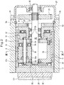
- the linear motion mechanism 6 includes a rotary shaft 20, a plurality of planetary rollers 21 kept in rolling contact with a cylindrical surface formed on the outer periphery of the rotary shaft 20, an outer ring member 22 surrounding the planetary rollers 21, and a carrier 23 supporting the planetary rollers 21 so as to be rotatable about their respective axes.
- the linear motion mechanism further includes a magnetic load sensor 24 arranged axially rearward of the outer ring member 22.
- the rotary shaft 20 is connected to the electric motor 1 through a gear mechanism (not shown) such that the rotation of the electric motor 1 is transmitted to the rotary shaft 20 through a gear 25.
- the rotary shaft 20 is inserted in the mounting hole 11, which extends through the inner portion 8 of the caliper body 4, with one end thereof protruding from the axially rear opening of the mounting hole 11.
- the gear 25 is rotationally fixed to the protruding portion of the rotary shaft 20 by means of splines.
- the gear 25 is covered with a lid 27 fixed in position by bolts 26 to close the axially rear opening of the mounting hole 11.
- a bearing 28 is mounted in the lid 27 to rotatably support the rotary shaft 20.
- the planetary rollers 21 are arranged so as to be circumferentially spaced apart from each other, and kept in rolling contact with the cylindrical surface formed on the outer periphery of the rotary shaft 20, such that when the rotary shaft 20 rotates, the planetary rollers 21 rotate due to friction between planetary rollers 21 and the rotary shaft 20.
- the outer ring member 22 is mounted in the mounting hole 11, which is formed in the inner portion 8 of the caliper body 4, and axially slidably supported by the inner periphery of the mounting hole 11.
- the outer ring member 22 is formed, in its axially front end surface, with an engaging recess 30 in which an engaging protrusion 29 formed on the rear surface of the inner pad 5b. Due to the engagement of the engaging protrusion 29 in the engaging recess 30, the outer ring member 22 is rotationally fixed to the caliper body 4.
- a helical rib 31 is formed on the inner periphery of the outer ring member 22.
- the helical rib 31 is engaged in circumferential grooves 32 formed in the outer periphery of each planetary roller 21.
- the outer ring member 22 is moved in the axial direction with the helical rib 31 guided by the circumferential grooves 32.
- a helical groove having a different lead angle from the helical rib 31 may be formed in the outer periphery of each planetary roller 21.
- the carrier 23 includes carrier pins 23a rotatably supporting the respective planetary rollers 21, an annular carrier plate 26c keeping constant the circumferential distances between the axial front ends of the respective adjacent carrier pins 23a, and an annular carrier body 23b keeping constant the circumferential distances between the axial rear ends of the respective adjacent carrier pins 23a.
- the carrier body 23b and the carrier plate 23c are opposed to each other with the planetary rollers 21 disposed therebetween, and are coupled together by coupling rods 33 disposed between the circumferentially adjacent planetary rollers 21.
- the carrier body 23b is supported by the rotary shaft 20 through a slide bearing 34 so as to be rotatable relative to the rotary shaft 20.
- a thrust bearing 35 is mounted between each planetary roller 21 and the carrier body 23b to prevent the rotation of the planetary roller 21 about its axis from being transmitted to the carrier body 23b.
- the carrier pins 23a which are arranged circumferentially spaced apart from each other, are biased radially inwardly by ring springs 36 wrapped around the carrier pins 23s such that the ring springs 36 tend to be radially compressed.
- the outer peripheries of the planetary rollers 21 are pressed against the outer periphery of the rotary shaft 20 under the biasing force of the ring springs 36, preventing slippage between the rotary shaft 20 and the planetary rollers 21.
- the ring springs 36 are wrapped around the front axial ends and the rear axial ends, respectively, of the carrier pins 23a.
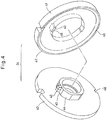
- the magnetic load sensor 24 includes a flange member 40 in the form of an annular plate, a support member 41 axially facing, while being axially spaced apart from, the flange member 40, a magnetic target 42 which generates a magnetic field, and a magnetic sensor element 43 configured to detect the intensity of a magnetic field.
- the flange member 40 includes a tubular portion 44 extending into the support member 41 and having a radially outer surface radially facing the radially inner surface of the support member 41.
- the magnetic target 42 is fixed to a chamfered 45 formed on the radially outer surface of the tubular portion 44.
- the magnetic sensor element 43 is fixed in a groove 46 formed in the radially inner surface of the support member 41.
- the flange member 40 and the support member 41 are made of a magnetic material such as iron.
- the support member 41 includes an annular wall 47 formed on the surface thereof facing the flange member 40.
- the annular wall 47 supports the radially outer portion of the flange member 40, keeping the flange member 40 and the support member 41 spaced apart from each other.
- the magnetic target 42 includes two permanent magnets each radially magnetized so as to have magnetic poles at the radially inner and outer ends thereof, respectively, and arranged side by side with the N- and S-poles of one of the two permanent magnets axially aligned with the S- and N-poles of the other of the two permanent magnets, respectively.
- the magnetic sensor element 43 comprises a Hall IC in the embodiment, but may be one other than a Hall IC, such as an MR sensor element or an MI sensor element.
- the magnetic sensor element 43 is arranged so as to face the boundary between the two adjacent permanent magnets forming the magnetic target 42, or to face the vicinity of this boundary, in a direction perpendicular to the axis of the sensor (radial direction in the figures), so as to be in the same circumferential position.
- the flange member 40 and the support member 41 of the magnetic load sensor 24 are formed, in their respective outer peripheries, with positioning grooves 48 and 49 having circular arc-shaped sections and arranged such that by fitting a key member 50 (see Fig. 2 ) in both positioning grooves 48 and 49, the flange member 40 and the support member 41 are circumferentially positioned relative to each other such that the circumferential positions of the magnetic target 42 and the magnetic sensor element 42 coincide with each other.
- a load acts on the flange member 40 in the axial direction toward the support member 41, such axial load axially deflects the flange member 40 about its outer peripheral portion.
- the magnetic load sensor 24 is fitted in the mounting hole 11 with the support member 41 positioned axially rearward of the flange member 40.
- a spacer 51 which is configured to revolve around the rotary shaft 20 together with the carrier 23, and a thrust bearing 52 through which axial torque is transmitted between the spacer 51 and the magnetic load sensor 24.
- Rolling bearings 53 are mounted inside of the inner periphery of the flange member 40, rotatably supporting the rotary shaft 20.
- the magnetic load sensor 24 in turn prevents axial rearward movement of the carrier 23 by axially supporting the carrier body 23b through the spacer 51 and the thrust bearing 52.
- the carrier 23 is therefore prevented from both axial forward and rearward movements, so that the planetary rollers 21, held by the carrier 23, are also prevented from both axial forward and rearward movements.
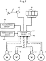
- the control means 3 comprises an engine control unit (ECU) for brake control including a microcomputer. As shown in Fig. 7 , to the control means 3 are connected a plurality of the electric brakes 2, a vehicle speed sensor 60, wheel speed sensors 61, a pedal sensor 62 and an acceleration sensor 63.
- ECU engine control unit
- brake loads are entered from the magnetic load sensors 24 of the electric brakes 2 for the respective wheels W, and a vehicle speed signal is entered from the vehicle speed sensor 60, which is calculated based on the number of revolutions of an axle.
- wheel speeds calculated based on the numbers of revolutions of the respective wheels W
- the load command output from the pedal sensor 62 which comprises a stroke sensor, a pressure sensor or the like
- the acceleration sensor 63 which is an element of an anti-lock control system (ABS).
- ABS anti-lock control system
- the control means 3 calculates a control output corresponding to the brake operation, while also taking into consideration e.g., the direction in which the vehicle is traveling, which can be calculated from the vehicle speed detected by the vehicle speed sensor 60, and the wheel speeds detected by the wheel speed sensors 61.
- the control means 3 applies the thus calculated control output to the electric motors 1 of the electric brakes 2.
- the control output actuates the electric motor 1 of each electric brake 2 to rotate the rotary shaft 20, which is coupled to the motor 1 through the gear mechanism.
- This causes the planetary rollers 21 to rotate about the respective carrier pins 23a while revolving around the rotary shaft 20.
- This in turn causes relative axial movement between the outer ring member 22 and the planetary rollers 21 due to engagement of the helical rib 31 in the circumferential grooves 32.
- the carrier 23 and thus the planetary rollers 21 are prevented from axial movement, only the outer ring member 22 is actually moved in the axial direction, with the planetary rollers 21 remaining stationary in the axial direction.
- the linear motion actuator 6 thus converts the rotation of the rotary shaft 20, driven by the electric motor 1, to an axial linear motion of the outer ring member 22.
- the inner pad 5b is pressed against the brake disk 7 under an axial load applied from the outer ring member 22, thus generating a braking force.
- a reaction force to the axial load is applied axially rearwardly to the outer ring member 22.
- the reaction force moves the caliper body 4 axially rearwardly through the planetary rollers 21, carrier 23, spacer 51 and thrust bearing 52, thus pressing the outer pad 5a mounted to the outer portion 9 of the caliper body 4 against the brake disk 7.
- the brake disk 7 is thus pressed by the outer pad 5a and the inner pad 5b from both sides.
- the reaction force applied to the outer ring member 22 is simultaneously received by the magnetic load sensor 24.
- the flange member 40 of the magnetic load sensor 24 is deflected axially rearwardly, so that the relative position between the magnetic target 42 and the magnetic sensor element 43, which in turn correspondingly changes the output signal 42 of the magnetic sensor element 43.
- the output signal 42 is fed back to the control means 3, and the control means 3 controls the braking load so as to follow the depressing amount of the brake pedal B (load command output) as shown by ⁇ in Fig. 8(a) .
- the control means 3 detects that the vehicle has been brought to a stop based on the output from the vehicle speed sensor 60 as a vehicle speed detecting means, and/or the outputs from the wheel speed sensors 11 as another vehicle speed detecting means.
- the control means 3 is preferably configured to determine that the vehicle has stopped after a zero vehicle speed has been detected for a predetermined period and thus inertia has disappeared after the vehicle has actually stopped.
- the vehicle speed sensor 60 and/or the wheel speed sensors 61 are used as the speed detecting means.
- the vehicle speed may be detected by integrating the output from the acceleration sensor 63 of the ABS.
- the vehicle speed can be detected not from the rotation of the wheels or an axle, but from the acceleration of the vehicle, and it is thus possible to determine that the vehicle has stopped by detecting that the acceleration has decreased to zero. It is therefore possible to shorten the above predetermined time period during which a zero vehicle speed is detected.
- control means 3 When the control means 3 detects that the vehicle has stopped, it changes the control output (operating variable) of the electric motor 1, as shown by y in Fig. 8 .
- the control means 3 when the control means 3 detects that the vehicle has stopped, the control means 3 memorizes the depressed amount of the brake pedal B when the control means 3 detects that the vehicle has stopped. Specifically, the control means 3 temporarily memorizes the load command output from the pedal sensor 62, and maintains the braking load corresponding to the depressed amount of the brake pedal. The control means then uses output properties in which a dead band D is provided which ranges above and below a set value which is a load command output of the brake pedal B corresponding to the maintained braking load and in which the control output does not change with the load command output of the brake pedal B.
- the dead band D can be realized easily by processing the program because the output properties can be changed in a stepwise manner by adding or subtracting a constant to or from the central value.
- the control means does not change the braking load.
- the brake pedal is unnecessarily operated while the vehicle is at a stop, the electric motors 1 will not be actuated.
- the dead band D While the dead band D is provided, if a large braking load is necessary while the vehicle is at a stop, such large braking load can be generated by depressing the brake pedal B hard such that the load command output of the brake pedal B overshoots the dead band D. Conversely, by releasing the brake pedal B, since the load command output of the brake pedal B falls below the dead band D, the brakes can be released. Thus, by determining the width of the dead band D such that the above states are possible within the operation range of the brake pedal B, the dead band will not interfere with normal braking operation.
- Example 1 in which the dead band D is used while the vehicle is traveling, is described with reference to Fig. 8(a) .
- the control means uses a dead band d to be used while the vehicle is traveling when the control means detects that the vehicle is traveling based on the output from the vehicle speed sensor 60 as a vehicle speed detecting means, and/or the outputs from the wheel speed sensors 61 as another vehicle speed detecting means.
- the dead band d while the vehicle is traveling is set using the load command output when the depressed amount of the brake pedal B becomes constant. It is possible to detect this constant output by holding the peak of the load command output (a peak hold circuit may be used for this purpose).
- the dead band d used while the vehicle is traveling is not configured to absorb large strokes of the brake pedal when the brake pedal is unintentionally loosened or additionally depressed, as with the dead band D used while the vehicle is at a stop, and if the dead band d is not configured to absorb only small strokes during deceleration, there may be a delay in brake operation.
- the dead band d used while the vehicle is traveling has to be narrower in width (range) than the dead band D while the vehicle is at a stop.
- the width of the dead band d is determined by experiments or based on experience.
- control means detects that the vehicle has stopped based on the output of the vehicle speed sensor 60 as a vehicle speed detecting means, and/or the outputs of the wheel speed sensors 61 as another vehicle speed detecting means, processing using the dead band D described in the embodiment is carried out.
- the dead band is controlled by measuring the time period during which the vehicle is at a stop.
- the control means 3 includes a timer means 70 shown by broken line in Fig. 7 .
- the timer means 70 measures the time period during which the vehicle is at a stop, and is configured to start measuring time when the control means 3 detects that the vehicle has been brought to stop based on the vehicle speed sensor 60, the wheel speed sensors 61 and/or the acceleration sensor 63.
- the timer means 70 After starting measuring time, the timer means 70 outputs time-up signals at predetermined time intervals. Every time a time-up signal is generated, the control means 3 increases the width of the dead band D by a predetermined value, to cope with the fatigue of the operator.
- the width of the dead band D is increased. How much and at what timing the width of the dead band D is increased is determined in an appropriate manner. As a result, it is possible to reduce unnecessary braking operation and thus reduce power consumption. Needless to say, there is an upper limit above which the width of the dead band cannot be increased.
- Example 3 control is carried out more accurately corresponding to the braking operation of the operator by taking into consideration the "play" of the brake pedal B (as well as the distance of the brake pedal to the floor when the brake pedal is depressed to the limit).
- the "play” of the brake pedal is considered to be a mechanical dead band of the brake pedal B.
- the “play” of the brake pedal of each vehicle slightly differs from those of other vehicles due to pedal adjustments of the respective vehicles. This could cause a difference between the operation of the brake pedal B and the braking behavior.
- the pedal sensor 62 and the magnetic load sensor 24 of each electric brake 2 are used.
- control means 3 can eliminate the difference due to the "play" of the brake pedal B. Thus, by eliminating any unnecessary brake operation due to this difference, it is possible to reduce power consumption.
- Example 4 is directed to a different type of linear motion mechanism 6 used in each electric brake.
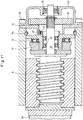
- Fig. 9 shows a ball-screw mechanism as the linear motion mechanism 6, which includes a threaded shaft 80 integral with the rotary shaft 20, a nut 81 surrounding the threaded shaft 80, and a plurality of balls 84 disposed between a thread groove 82 formed in the outer periphery of the threaded shaft 80 and a thread groove 83 formed in the inner periphery of the nut 81.
- This linear motion mechanism 6 further includes a return tube 85 for returning the balls 84 from the end point to the starting point, of the thread groove 83 of the nut 81 so as to surround the balls 84, and the magnetic load sensor 24, which is disposed axially rearwardly of the nut 81.
- This linear motion mechanism 6 is configured such that when the rotary shaft 20 is rotated, the threaded shaft 80 and the nut 81 are rotated relative to each other such that the nut 81 moves axially forward, thus applying an axial load to the inner pad 5b. At this time, an axially rearward reaction force acts on the threaded shaft 80. The reaction force is then transmitted to the magnetic load sensor 24 through the spacer 51 and the thrust bearing 52. Under this reaction force, the flange member 40 of the magnetic load sensor 24 is axially rearwardly deflected, thus changing the relative position between the magnetic target 42 and the magnetic sensor unit 43. As a result, the output signal of the magnetic sensor unit 43 changes according to the intensity of the axial load applied to the inner pad 5b, so that it is possible to detect the pressure applied to the inner pad 56 based on the output signal of the magnetic sensor 43.
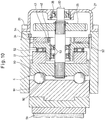
- the linear motion mechanism 6 shown in Fig. 10 is a ball-ramp mechanism including a rotary disk 90 rotationally fixed to outer periphery of the rotary shaft 20, a linear motion disk 91 located axially forwardly of and axially facing the rotary disk 90, and a plurality of balls 92 disposed between the linear motion disk 91 and the rotary disk 90.
- This linear motion mechanism further includes the magnetic load sensor 24, which is provided axially rearwardly of the linear motion disk 91.
- This linear motion mechanism 6 is configured such that when the rotary shaft 20 is rotated, the linear motion disk 91 and rotary disk 90 are rotated relative to each other such that the linear motion disk 91 moves axially, thus applying an axial load to the inner pad 5b.
- an axially rearward reaction force acts on the rotary disk 90.
- the reaction force is then transmitted to the magnetic load sensor 24 through the spacer 51 and the thrust bearing 52.
- the flange member 40 of the magnetic load sensor 24 is axially rearwardly deflected, thus changing the relative position between the magnetic target 42 and the magnetic sensor unit 43.
- the output signal of the magnetic sensor unit 43 changes according to the intensity of the axial load applied to the inner pad 5b, so that it is possible to detect the pressure applied to the inner pad 5b based on the output signal of the magnetic sensor 43.
- the linear motion mechanism 6 shown in Fig. 11 is a slide screw mechanism, which differs from the ball-screw mechanism of Fig. 9 in that a trapezoidal screw is used as a ball-screw. Otherwise, this linear motion mechanism is identical to that shown in Fig. 9 , and its description is omitted.
- Such a slide screw mechanism can be advantageously used for a vehicle brake, which is used under high loads and which is vertically vibrated.
Landscapes
- Engineering & Computer Science (AREA)
- Mechanical Engineering (AREA)
- Transportation (AREA)
- General Engineering & Computer Science (AREA)
- Regulating Braking Force (AREA)
- Braking Arrangements (AREA)
Claims (6)
- Elektrisches Bremssystem, das umfasst:eine elektrische Bremse (2), die eine Drehwelle (20), die so eingerichtet ist, dass sie von einem Elektromotor (1) angetrieben wird, einen Bremsbelag (5), einen Linearbewegungs-Mechanismus (6), der so eingerichtet ist, dass er eine Drehung der Drehwelle (20) in eine Linearbewegung des Bremsbelages (5) umwandelt und so den Bremsbelag (5) an eine Bremsscheibe (7) presst; sowieeine Steuereinrichtung (3), die so eingerichtet ist, dass sie einen Erfassungs-Ausgang einer Last-Erfassungseinrichtung (24) zum Erfassen der Stärke einer auf die Bremsscheibe (7) wirkenden Last, einen von einem Bremspedal (B) ausgegebenen Bremslast-Befehl und einen Erfassungs-Ausgang einer Fahrzeuggeschwindigkeits-Erfassungseinrichtung (60, 61, 63) zum Erfassen einer Fahrzeuggeschwindigkeit empfängt und den Elektromotor (1) auf Basis der empfangenen Ausgänge steuert,wobei die Steuereinrichtung (3) mit einem Unempfindlichkeitsbereich (D) versehen ist, innerhalb dessen eine durch den Linearbewegungs-Mechanismus (6) ausgeübte Bremslast sich selbst dann nicht ändert, wenn der von dem Bremspedal (B) ausgegebene Last-Befehl von dem Erfassungs-Ausgang der Last-Erfassungseinrichtung (24) abweicht, wenn auf Basis des Erfassungs-Signals der Fahrzeuggeschwindigkeits-Erfassungseinrichtung (60, 61, 63) erfasst wird, dass ein Fahrzeug im Stillstand ist, unddie Steuereinrichtung (3) so eingerichtet ist, dass sie feststellt, dass das Fahrzeug im Stillstand ist, wenn der Erfassungs-Ausgang der Fahrzeuggeschwindigkeits-Erfassungseinrichtung (60, 61, 63) zum Erfassen der Fahrzeuggeschwindigkeit über einen vorgegebenen Zeitraum 0 bleibt.
- Elektrisches Bremssystem nach Anspruch 1, wobei die Steuereinrichtung (3) mit einem Unempfindlichkeitsbereich (D) versehen ist, innerhalb dessen eine durch den Linearbewegungs-Mechanismus (6) ausgeübte Bremslast sich selbst dann nicht ändert, wenn der von dem Bremspedal (B) ausgegebene Last-Befehl von dem Erfassungs-Ausgang der Last-Erfassungseinrichtung (24) abweicht, wenn auf Basis des Erfassungs-Signals der Fahrzeuggeschwindigkeits-Erfassungseinrichtung (60, 61, 63) erfasst wird, dass ein Fahrzeug sich bewegt.
- Elektrisches Bremssystem nach Anspruch 1 oder 2, das des Weiteren eine Zeitglied-Einrichtung (70) umfasst, mit der ein Zeitraum erfasst wird, in dem das Fahrzeug im Stillstand ist, und die Steuereinrichtung (3) so eingerichtet ist, dass sie eine Breite des Unempfindlichkeitsbereiches (D) auf Basis des durch die Zeitglied-Einrichtung (70) erfassten Zeitraums ändert.
- Elektrisches Bremssystem nach Anspruch 1 oder 3, das des Weiteren eine Spiel-Erfassungseinrichtung (24, 62) umfasst, mit der ein Spiel des Bremspedals (B) erfasst wird, und die Steuereinrichtung (3) so eingerichtet ist, dass sie eine Breite des Unempfindlichkeitsbereiches (D) auf Basis des durch die Spiel-Erfassungseinrichtung (24, 62) erfassten Spiels ändert.
- Elektrisches Bremssystem nach einem der Ansprüche 1 bis 4, wobei die Fahrzeuggeschwindigkeits-Erfassungseinrichtung (60, 61, 63) einen Radgeschwindigkeits-Sensor (61) umfasst, der an einem Fahrzeugrad installiert ist.
- Elektrisches Bremssystem nach einem der Ansprüche 1 bis 4, wobei die Fahrzeuggeschwindigkeits-Erfassungseinrichtung (60, 61, 63) einen Beschleunigungs-Sensor (63) umfasst.
Applications Claiming Priority (2)
| Application Number | Priority Date | Filing Date | Title |
|---|---|---|---|
| JP2013000994A JP6182314B2 (ja) | 2013-01-08 | 2013-01-08 | 電動ブレーキ装置 |
| PCT/JP2014/050016 WO2014109298A1 (ja) | 2013-01-08 | 2014-01-06 | 電動ブレーキ装置 |
Publications (3)
| Publication Number | Publication Date |
|---|---|
| EP2944525A1 EP2944525A1 (de) | 2015-11-18 |
| EP2944525A4 EP2944525A4 (de) | 2016-01-20 |
| EP2944525B1 true EP2944525B1 (de) | 2018-05-23 |
Family
ID=51166946
Family Applications (1)
| Application Number | Title | Priority Date | Filing Date |
|---|---|---|---|
| EP14738019.0A Not-in-force EP2944525B1 (de) | 2013-01-08 | 2014-01-06 | Elektrisches bremssystem |
Country Status (5)
| Country | Link |
|---|---|
| US (1) | US9840237B2 (de) |
| EP (1) | EP2944525B1 (de) |
| JP (1) | JP6182314B2 (de) |
| CN (1) | CN104903165B (de) |
| WO (1) | WO2014109298A1 (de) |
Families Citing this family (8)
| Publication number | Priority date | Publication date | Assignee | Title |
|---|---|---|---|---|
| JP6080682B2 (ja) * | 2013-05-17 | 2017-02-15 | Ntn株式会社 | 電動式直動アクチュエータおよび電動ブレーキ装置 |
| JP6336273B2 (ja) | 2013-12-24 | 2018-06-06 | Ntn株式会社 | 車両用ブレーキ装置 |
| US10232834B2 (en) | 2014-12-27 | 2019-03-19 | Mazda Motor Corporation | Brake device |
| JP6325493B2 (ja) * | 2015-07-29 | 2018-05-16 | 株式会社アドヴィックス | 車両用制動装置 |
| US10137878B2 (en) | 2015-10-14 | 2018-11-27 | Akebono Brake Industry Co., Ltd. | Method for controlling a parking brake system |
| EP3473891A4 (de) * | 2016-06-16 | 2019-06-19 | NTN Corporation | Elektrisches lineares stellglied und elektrische bremsvorrichtung |
| CN106184165A (zh) * | 2016-08-05 | 2016-12-07 | 北京新能源汽车股份有限公司 | 刹车控制方法、装置及汽车 |
| JP2018105806A (ja) * | 2016-12-28 | 2018-07-05 | Ntn株式会社 | 荷重センサおよび電動ブレーキ装置 |
Family Cites Families (18)
| Publication number | Priority date | Publication date | Assignee | Title |
|---|---|---|---|---|
| FR2699486A1 (fr) | 1992-12-23 | 1994-06-24 | Peugeot | Dispositif de freinage pour véhicule automobile. |
| JP3166401B2 (ja) | 1993-05-17 | 2001-05-14 | 日産自動車株式会社 | 電動ブレーキ用アクチュエータ |
| JPH09175352A (ja) * | 1995-12-26 | 1997-07-08 | Mitsubishi Motors Corp | 坂道発進補助装置 |
| US6003640A (en) * | 1997-05-09 | 1999-12-21 | The B.F. Goodrich Company | Electronic braking system with brake wear measurement and running clearance adjustment |
| JP2001063537A (ja) * | 1999-08-25 | 2001-03-13 | Nissan Motor Co Ltd | 電動ブレーキ装置 |
| JP2003194119A (ja) * | 2001-12-28 | 2003-07-09 | Nissan Motor Co Ltd | 電動ブレーキ装置 |
| FR2835896B1 (fr) * | 2002-02-12 | 2005-06-10 | Delphi Tech Inc | Dispositif pour detecter un contact entre deux elements de frein d'un systeme de frenage |
| JP2004142514A (ja) * | 2002-10-22 | 2004-05-20 | Honda Motor Co Ltd | 電動駐車ブレーキ装置 |
| JP2005088787A (ja) * | 2003-09-18 | 2005-04-07 | Nsk Ltd | ブレーキ制御装置 |
| WO2005119083A1 (en) * | 2004-06-04 | 2005-12-15 | Goodrich Corporation | Electric brake position and force sensing and control |
| GB0500305D0 (en) * | 2005-01-08 | 2005-02-16 | Dunlop Aerospace Ltd | Electrically actuated aircraft brakes |
| JP4898123B2 (ja) | 2005-01-13 | 2012-03-14 | Ntn株式会社 | 電動式直動アクチュエータおよび電動式ブレーキ装置 |
| JP4610430B2 (ja) * | 2005-07-08 | 2011-01-12 | 日立オートモティブシステムズ株式会社 | 電動ブレーキ装置 |
| EP1954538B1 (de) * | 2005-11-30 | 2014-05-21 | Goodrich Corporation | Steuerung für elektromechanisches bremssystem mit spielnachstellung und verfahren |
| JP4470928B2 (ja) | 2006-09-15 | 2010-06-02 | トヨタ自動車株式会社 | 電動パーキングブレーキシステム |
| JP2010111230A (ja) * | 2008-11-05 | 2010-05-20 | Toyota Motor Corp | 車両制御装置とブレーキ電子制御装置と電動パワーステアリング装置 |
| JP5284241B2 (ja) * | 2009-10-08 | 2013-09-11 | 日信工業株式会社 | 車両用ブレーキ圧制御装置 |
| JP5381954B2 (ja) * | 2010-10-20 | 2014-01-08 | 三菱自動車工業株式会社 | 車両駆動力制御装置 |
-
2013
- 2013-01-08 JP JP2013000994A patent/JP6182314B2/ja active Active
-
2014
- 2014-01-06 CN CN201480004318.5A patent/CN104903165B/zh not_active Expired - Fee Related
- 2014-01-06 EP EP14738019.0A patent/EP2944525B1/de not_active Not-in-force
- 2014-01-06 US US14/759,423 patent/US9840237B2/en not_active Expired - Fee Related
- 2014-01-06 WO PCT/JP2014/050016 patent/WO2014109298A1/ja not_active Ceased
Non-Patent Citations (1)
| Title |
|---|
| None * |
Also Published As
| Publication number | Publication date |
|---|---|
| US20150360656A1 (en) | 2015-12-17 |
| JP2014133429A (ja) | 2014-07-24 |
| JP6182314B2 (ja) | 2017-08-16 |
| US9840237B2 (en) | 2017-12-12 |
| CN104903165A (zh) | 2015-09-09 |
| EP2944525A1 (de) | 2015-11-18 |
| WO2014109298A1 (ja) | 2014-07-17 |
| CN104903165B (zh) | 2018-04-20 |
| EP2944525A4 (de) | 2016-01-20 |
Similar Documents
| Publication | Publication Date | Title |
|---|---|---|
| US9840237B2 (en) | Electric brake system | |
| EP2907709B1 (de) | Elektrische feststellbremsvorrichtung | |
| EP3056400B1 (de) | Elektrische bremsvorrichtung mit bremsenfeststellfunktion | |
| JP5625527B2 (ja) | 電動ブレーキ装置 | |
| JP7136058B2 (ja) | 電磁ブレーキ装置 | |
| EP2775170B1 (de) | Elektrischer linearbewegungsaktuator | |
| WO2019163595A1 (ja) | 電動ブレーキおよび制御装置 | |
| JP5614528B2 (ja) | ディスクブレーキ | |
| JP4937972B2 (ja) | 電動式ディスクブレーキ装置 | |
| US20020185340A1 (en) | Electronic controlled brake device | |
| JP5384974B2 (ja) | 電動ブレーキ | |
| JP5077604B2 (ja) | 電動ディスクブレーキ | |
| JP7239530B2 (ja) | 電動ブレーキ装置 | |
| JP5257636B2 (ja) | 電動ディスクブレーキ | |
| JP2003194115A (ja) | 電動ディスクブレーキおよびその制御プログラム | |
| JP2007132397A (ja) | 電動ブレーキ駆動装置 | |
| JP5296908B2 (ja) | 電動ブレーキ | |
| JP5416817B2 (ja) | 電動ブレーキ | |
| JP2005088787A (ja) | ブレーキ制御装置 | |
| KR20130011842A (ko) | 차량용 제동장치 | |
| JP2017226291A (ja) | 電動ブレーキ装置 | |
| KR20090061180A (ko) | 롤러 인 램프 타입 전동 브레이크 시스템 |
Legal Events
| Date | Code | Title | Description |
|---|---|---|---|
| PUAI | Public reference made under article 153(3) epc to a published international application that has entered the european phase |
Free format text: ORIGINAL CODE: 0009012 |
|
| 17P | Request for examination filed |
Effective date: 20150805 |
|
| AK | Designated contracting states |
Kind code of ref document: A1 Designated state(s): AL AT BE BG CH CY CZ DE DK EE ES FI FR GB GR HR HU IE IS IT LI LT LU LV MC MK MT NL NO PL PT RO RS SE SI SK SM TR |
|
| AX | Request for extension of the european patent |
Extension state: BA ME |
|
| A4 | Supplementary search report drawn up and despatched |
Effective date: 20151221 |
|
| RIC1 | Information provided on ipc code assigned before grant |
Ipc: B60T 8/00 20060101AFI20151215BHEP |
|
| DAX | Request for extension of the european patent (deleted) | ||
| GRAP | Despatch of communication of intention to grant a patent |
Free format text: ORIGINAL CODE: EPIDOSNIGR1 |
|
| STAA | Information on the status of an ep patent application or granted ep patent |
Free format text: STATUS: GRANT OF PATENT IS INTENDED |
|
| INTG | Intention to grant announced |
Effective date: 20180102 |
|
| GRAS | Grant fee paid |
Free format text: ORIGINAL CODE: EPIDOSNIGR3 |
|
| GRAA | (expected) grant |
Free format text: ORIGINAL CODE: 0009210 |
|
| STAA | Information on the status of an ep patent application or granted ep patent |
Free format text: STATUS: THE PATENT HAS BEEN GRANTED |
|
| AK | Designated contracting states |
Kind code of ref document: B1 Designated state(s): AL AT BE BG CH CY CZ DE DK EE ES FI FR GB GR HR HU IE IS IT LI LT LU LV MC MK MT NL NO PL PT RO RS SE SI SK SM TR |
|
| REG | Reference to a national code |
Ref country code: GB Ref legal event code: FG4D |
|
| REG | Reference to a national code |
Ref country code: CH Ref legal event code: EP |
|
| REG | Reference to a national code |
Ref country code: IE Ref legal event code: FG4D |
|
| REG | Reference to a national code |
Ref country code: DE Ref legal event code: R096 Ref document number: 602014025856 Country of ref document: DE |
|
| REG | Reference to a national code |
Ref country code: AT Ref legal event code: REF Ref document number: 1001269 Country of ref document: AT Kind code of ref document: T Effective date: 20180615 |
|
| REG | Reference to a national code |
Ref country code: NL Ref legal event code: MP Effective date: 20180523 |
|
| REG | Reference to a national code |
Ref country code: LT Ref legal event code: MG4D |
|
| PG25 | Lapsed in a contracting state [announced via postgrant information from national office to epo] |
Ref country code: ES Free format text: LAPSE BECAUSE OF FAILURE TO SUBMIT A TRANSLATION OF THE DESCRIPTION OR TO PAY THE FEE WITHIN THE PRESCRIBED TIME-LIMIT Effective date: 20180523 Ref country code: NO Free format text: LAPSE BECAUSE OF FAILURE TO SUBMIT A TRANSLATION OF THE DESCRIPTION OR TO PAY THE FEE WITHIN THE PRESCRIBED TIME-LIMIT Effective date: 20180823 Ref country code: SE Free format text: LAPSE BECAUSE OF FAILURE TO SUBMIT A TRANSLATION OF THE DESCRIPTION OR TO PAY THE FEE WITHIN THE PRESCRIBED TIME-LIMIT Effective date: 20180523 Ref country code: FI Free format text: LAPSE BECAUSE OF FAILURE TO SUBMIT A TRANSLATION OF THE DESCRIPTION OR TO PAY THE FEE WITHIN THE PRESCRIBED TIME-LIMIT Effective date: 20180523 Ref country code: LT Free format text: LAPSE BECAUSE OF FAILURE TO SUBMIT A TRANSLATION OF THE DESCRIPTION OR TO PAY THE FEE WITHIN THE PRESCRIBED TIME-LIMIT Effective date: 20180523 Ref country code: BG Free format text: LAPSE BECAUSE OF FAILURE TO SUBMIT A TRANSLATION OF THE DESCRIPTION OR TO PAY THE FEE WITHIN THE PRESCRIBED TIME-LIMIT Effective date: 20180823 |
|
| PG25 | Lapsed in a contracting state [announced via postgrant information from national office to epo] |
Ref country code: GR Free format text: LAPSE BECAUSE OF FAILURE TO SUBMIT A TRANSLATION OF THE DESCRIPTION OR TO PAY THE FEE WITHIN THE PRESCRIBED TIME-LIMIT Effective date: 20180824 Ref country code: NL Free format text: LAPSE BECAUSE OF FAILURE TO SUBMIT A TRANSLATION OF THE DESCRIPTION OR TO PAY THE FEE WITHIN THE PRESCRIBED TIME-LIMIT Effective date: 20180523 Ref country code: RS Free format text: LAPSE BECAUSE OF FAILURE TO SUBMIT A TRANSLATION OF THE DESCRIPTION OR TO PAY THE FEE WITHIN THE PRESCRIBED TIME-LIMIT Effective date: 20180523 Ref country code: HR Free format text: LAPSE BECAUSE OF FAILURE TO SUBMIT A TRANSLATION OF THE DESCRIPTION OR TO PAY THE FEE WITHIN THE PRESCRIBED TIME-LIMIT Effective date: 20180523 Ref country code: LV Free format text: LAPSE BECAUSE OF FAILURE TO SUBMIT A TRANSLATION OF THE DESCRIPTION OR TO PAY THE FEE WITHIN THE PRESCRIBED TIME-LIMIT Effective date: 20180523 |
|
| REG | Reference to a national code |
Ref country code: AT Ref legal event code: MK05 Ref document number: 1001269 Country of ref document: AT Kind code of ref document: T Effective date: 20180523 |
|
| PG25 | Lapsed in a contracting state [announced via postgrant information from national office to epo] |
Ref country code: SK Free format text: LAPSE BECAUSE OF FAILURE TO SUBMIT A TRANSLATION OF THE DESCRIPTION OR TO PAY THE FEE WITHIN THE PRESCRIBED TIME-LIMIT Effective date: 20180523 Ref country code: RO Free format text: LAPSE BECAUSE OF FAILURE TO SUBMIT A TRANSLATION OF THE DESCRIPTION OR TO PAY THE FEE WITHIN THE PRESCRIBED TIME-LIMIT Effective date: 20180523 Ref country code: CZ Free format text: LAPSE BECAUSE OF FAILURE TO SUBMIT A TRANSLATION OF THE DESCRIPTION OR TO PAY THE FEE WITHIN THE PRESCRIBED TIME-LIMIT Effective date: 20180523 Ref country code: EE Free format text: LAPSE BECAUSE OF FAILURE TO SUBMIT A TRANSLATION OF THE DESCRIPTION OR TO PAY THE FEE WITHIN THE PRESCRIBED TIME-LIMIT Effective date: 20180523 Ref country code: AT Free format text: LAPSE BECAUSE OF FAILURE TO SUBMIT A TRANSLATION OF THE DESCRIPTION OR TO PAY THE FEE WITHIN THE PRESCRIBED TIME-LIMIT Effective date: 20180523 Ref country code: DK Free format text: LAPSE BECAUSE OF FAILURE TO SUBMIT A TRANSLATION OF THE DESCRIPTION OR TO PAY THE FEE WITHIN THE PRESCRIBED TIME-LIMIT Effective date: 20180523 Ref country code: PL Free format text: LAPSE BECAUSE OF FAILURE TO SUBMIT A TRANSLATION OF THE DESCRIPTION OR TO PAY THE FEE WITHIN THE PRESCRIBED TIME-LIMIT Effective date: 20180523 |
|
| REG | Reference to a national code |
Ref country code: DE Ref legal event code: R097 Ref document number: 602014025856 Country of ref document: DE |
|
| PG25 | Lapsed in a contracting state [announced via postgrant information from national office to epo] |
Ref country code: IT Free format text: LAPSE BECAUSE OF FAILURE TO SUBMIT A TRANSLATION OF THE DESCRIPTION OR TO PAY THE FEE WITHIN THE PRESCRIBED TIME-LIMIT Effective date: 20180523 Ref country code: SM Free format text: LAPSE BECAUSE OF FAILURE TO SUBMIT A TRANSLATION OF THE DESCRIPTION OR TO PAY THE FEE WITHIN THE PRESCRIBED TIME-LIMIT Effective date: 20180523 |
|
| PLBE | No opposition filed within time limit |
Free format text: ORIGINAL CODE: 0009261 |
|
| STAA | Information on the status of an ep patent application or granted ep patent |
Free format text: STATUS: NO OPPOSITION FILED WITHIN TIME LIMIT |
|
| 26N | No opposition filed |
Effective date: 20190226 |
|
| PG25 | Lapsed in a contracting state [announced via postgrant information from national office to epo] |
Ref country code: SI Free format text: LAPSE BECAUSE OF FAILURE TO SUBMIT A TRANSLATION OF THE DESCRIPTION OR TO PAY THE FEE WITHIN THE PRESCRIBED TIME-LIMIT Effective date: 20180523 |
|
| PG25 | Lapsed in a contracting state [announced via postgrant information from national office to epo] |
Ref country code: MC Free format text: LAPSE BECAUSE OF FAILURE TO SUBMIT A TRANSLATION OF THE DESCRIPTION OR TO PAY THE FEE WITHIN THE PRESCRIBED TIME-LIMIT Effective date: 20180523 |
|
| REG | Reference to a national code |
Ref country code: CH Ref legal event code: PL |
|
| GBPC | Gb: european patent ceased through non-payment of renewal fee |
Effective date: 20190106 |
|
| PG25 | Lapsed in a contracting state [announced via postgrant information from national office to epo] |
Ref country code: LU Free format text: LAPSE BECAUSE OF NON-PAYMENT OF DUE FEES Effective date: 20190106 |
|
| REG | Reference to a national code |
Ref country code: BE Ref legal event code: MM Effective date: 20190131 |
|
| REG | Reference to a national code |
Ref country code: IE Ref legal event code: MM4A |
|
| PG25 | Lapsed in a contracting state [announced via postgrant information from national office to epo] |
Ref country code: BE Free format text: LAPSE BECAUSE OF NON-PAYMENT OF DUE FEES Effective date: 20190131 Ref country code: AL Free format text: LAPSE BECAUSE OF FAILURE TO SUBMIT A TRANSLATION OF THE DESCRIPTION OR TO PAY THE FEE WITHIN THE PRESCRIBED TIME-LIMIT Effective date: 20180523 |
|
| PG25 | Lapsed in a contracting state [announced via postgrant information from national office to epo] |
Ref country code: GB Free format text: LAPSE BECAUSE OF NON-PAYMENT OF DUE FEES Effective date: 20190106 Ref country code: LI Free format text: LAPSE BECAUSE OF NON-PAYMENT OF DUE FEES Effective date: 20190131 Ref country code: CH Free format text: LAPSE BECAUSE OF NON-PAYMENT OF DUE FEES Effective date: 20190131 |
|
| PG25 | Lapsed in a contracting state [announced via postgrant information from national office to epo] |
Ref country code: IE Free format text: LAPSE BECAUSE OF NON-PAYMENT OF DUE FEES Effective date: 20190106 |
|
| PG25 | Lapsed in a contracting state [announced via postgrant information from national office to epo] |
Ref country code: TR Free format text: LAPSE BECAUSE OF FAILURE TO SUBMIT A TRANSLATION OF THE DESCRIPTION OR TO PAY THE FEE WITHIN THE PRESCRIBED TIME-LIMIT Effective date: 20180523 |
|
| PG25 | Lapsed in a contracting state [announced via postgrant information from national office to epo] |
Ref country code: PT Free format text: LAPSE BECAUSE OF FAILURE TO SUBMIT A TRANSLATION OF THE DESCRIPTION OR TO PAY THE FEE WITHIN THE PRESCRIBED TIME-LIMIT Effective date: 20180924 Ref country code: MT Free format text: LAPSE BECAUSE OF NON-PAYMENT OF DUE FEES Effective date: 20190106 |
|
| PG25 | Lapsed in a contracting state [announced via postgrant information from national office to epo] |
Ref country code: CY Free format text: LAPSE BECAUSE OF FAILURE TO SUBMIT A TRANSLATION OF THE DESCRIPTION OR TO PAY THE FEE WITHIN THE PRESCRIBED TIME-LIMIT Effective date: 20180523 |
|
| PG25 | Lapsed in a contracting state [announced via postgrant information from national office to epo] |
Ref country code: IS Free format text: LAPSE BECAUSE OF FAILURE TO SUBMIT A TRANSLATION OF THE DESCRIPTION OR TO PAY THE FEE WITHIN THE PRESCRIBED TIME-LIMIT Effective date: 20180923 |
|
| PG25 | Lapsed in a contracting state [announced via postgrant information from national office to epo] |
Ref country code: HU Free format text: LAPSE BECAUSE OF FAILURE TO SUBMIT A TRANSLATION OF THE DESCRIPTION OR TO PAY THE FEE WITHIN THE PRESCRIBED TIME-LIMIT; INVALID AB INITIO Effective date: 20140106 |
|
| PGFP | Annual fee paid to national office [announced via postgrant information from national office to epo] |
Ref country code: FR Payment date: 20211217 Year of fee payment: 9 |
|
| PGFP | Annual fee paid to national office [announced via postgrant information from national office to epo] |
Ref country code: DE Payment date: 20211130 Year of fee payment: 9 |
|
| PG25 | Lapsed in a contracting state [announced via postgrant information from national office to epo] |
Ref country code: MK Free format text: LAPSE BECAUSE OF FAILURE TO SUBMIT A TRANSLATION OF THE DESCRIPTION OR TO PAY THE FEE WITHIN THE PRESCRIBED TIME-LIMIT Effective date: 20180523 |
|
| REG | Reference to a national code |
Ref country code: DE Ref legal event code: R119 Ref document number: 602014025856 Country of ref document: DE |
|
| PG25 | Lapsed in a contracting state [announced via postgrant information from national office to epo] |
Ref country code: DE Free format text: LAPSE BECAUSE OF NON-PAYMENT OF DUE FEES Effective date: 20230801 |
|
| PG25 | Lapsed in a contracting state [announced via postgrant information from national office to epo] |
Ref country code: FR Free format text: LAPSE BECAUSE OF NON-PAYMENT OF DUE FEES Effective date: 20230131 |