EP2944157B1 - System und verfahren zur kalibrierung eines verteilten verstärkersystems - Google Patents
System und verfahren zur kalibrierung eines verteilten verstärkersystems Download PDFInfo
- Publication number
- EP2944157B1 EP2944157B1 EP14703949.9A EP14703949A EP2944157B1 EP 2944157 B1 EP2944157 B1 EP 2944157B1 EP 14703949 A EP14703949 A EP 14703949A EP 2944157 B1 EP2944157 B1 EP 2944157B1
- Authority
- EP
- European Patent Office
- Prior art keywords
- head end
- coverage
- amplifier
- output power
- antenna
- Prior art date
- Legal status (The legal status is an assumption and is not a legal conclusion. Google has not performed a legal analysis and makes no representation as to the accuracy of the status listed.)
- Not-in-force
Links
Images

Classifications
-
- H—ELECTRICITY
- H04—ELECTRIC COMMUNICATION TECHNIQUE
- H04W—WIRELESS COMMUNICATION NETWORKS
- H04W52/00—Power management, e.g. TPC [Transmission Power Control], power saving or power classes
- H04W52/04—TPC
- H04W52/18—TPC being performed according to specific parameters
- H04W52/24—TPC being performed according to specific parameters using SIR [Signal to Interference Ratio] or other wireless path parameters
- H04W52/245—TPC being performed according to specific parameters using SIR [Signal to Interference Ratio] or other wireless path parameters taking into account received signal strength
-
- H—ELECTRICITY
- H03—ELECTRONIC CIRCUITRY
- H03G—CONTROL OF AMPLIFICATION
- H03G3/00—Gain control in amplifiers or frequency changers without distortion of the input signal
- H03G3/20—Automatic control
-
- H—ELECTRICITY
- H04—ELECTRIC COMMUNICATION TECHNIQUE
- H04B—TRANSMISSION
- H04B1/00—Details of transmission systems, not covered by a single one of groups H04B3/00 - H04B13/00; Details of transmission systems not characterised by the medium used for transmission
- H04B1/06—Receivers
- H04B1/16—Circuits
-
- H—ELECTRICITY
- H04—ELECTRIC COMMUNICATION TECHNIQUE
- H04B—TRANSMISSION
- H04B17/00—Monitoring; Testing
- H04B17/30—Monitoring; Testing of propagation channels
- H04B17/309—Measuring or estimating channel quality parameters
- H04B17/318—Received signal strength
-
- H—ELECTRICITY
- H04—ELECTRIC COMMUNICATION TECHNIQUE
- H04W—WIRELESS COMMUNICATION NETWORKS
- H04W16/00—Network planning, e.g. coverage or traffic planning tools; Network deployment, e.g. resource partitioning or cells structures
- H04W16/24—Cell structures
- H04W16/26—Cell enhancers or enhancement, e.g. for tunnels, building shadow
-
- H—ELECTRICITY
- H04—ELECTRIC COMMUNICATION TECHNIQUE
- H04W—WIRELESS COMMUNICATION NETWORKS
- H04W24/00—Supervisory, monitoring or testing arrangements
- H04W24/02—Arrangements for optimising operational condition
-
- H—ELECTRICITY
- H04—ELECTRIC COMMUNICATION TECHNIQUE
- H04W—WIRELESS COMMUNICATION NETWORKS
- H04W24/00—Supervisory, monitoring or testing arrangements
- H04W24/08—Testing, supervising or monitoring using real traffic
-
- H—ELECTRICITY
- H04—ELECTRIC COMMUNICATION TECHNIQUE
- H04W—WIRELESS COMMUNICATION NETWORKS
- H04W24/00—Supervisory, monitoring or testing arrangements
- H04W24/10—Scheduling measurement reports ; Arrangements for measurement reports
-
- H—ELECTRICITY
- H04—ELECTRIC COMMUNICATION TECHNIQUE
- H04W—WIRELESS COMMUNICATION NETWORKS
- H04W52/00—Power management, e.g. TPC [Transmission Power Control], power saving or power classes
- H04W52/04—TPC
- H04W52/52—TPC using AGC [Automatic Gain Control] circuits or amplifiers
-
- H—ELECTRICITY
- H04—ELECTRIC COMMUNICATION TECHNIQUE
- H04W—WIRELESS COMMUNICATION NETWORKS
- H04W88/00—Devices specially adapted for wireless communication networks, e.g. terminals, base stations or access point devices
- H04W88/08—Access point devices
- H04W88/085—Access point devices with remote components
Definitions
- the present disclosure relates to a telecommunication system, and more particularly, but not exclusively to a system and method for calibrating a distributed amplifier system.
- RF losses between a head end and nodes of a system will decrease performance of the system. Further, these RF losses can vary over time. Accordingly, a new system and method may be needed to calibrate the system over time to compensate for the RF losses.
- EP2159933 and US2008/0174502 disclose examples of distributed antenna systems.
- a method comprises measuring RF losses at multiple frequencies in both a first directions between a head end and a coverage node in a site by measuring output power from the head end and comparing that to input power on a plurality of coverage nodes as received from the coverage nodes for downlink loss and vice-versa for uplink loss; generating gains and output power limits for each amplifier in each coverage node and the head end based on the measured RF losses; and further adjusting the generated gains and output power limits based on downlink signal strength of cellular signals at a donor antenna.
- a distributed amplifier system comprises a head end and a plurality of coverage nodes distributed in a site and communicatively coupled to the head end.
- Each coverage node includes an amplifier and the head end includes an amplifier.
- the head end amplifier is configured to measure RF losses at multiple frequencies in a first direction between the head end and the coverage nodes by measuring output power from the head end and comparing that to input power on a plurality of coverage nodes as received from the coverage nodes for downlink loss; generate gains and output power limits for each amplifier in each coverage node and the head end based on the measured RF losses; and further adjust the generated gains and output power limits based on downlink signal strength of cellular signals at a donor antenna.
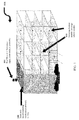
- FIG. 1 is a diagram illustrating a deployment of a distributed amplifier system 10A.
- the cellular signals from outdoor cellular towers may not provide clear and consistent coverage inside buildings, so wireless operators and building owners use distributed antenna systems 10A to broadcast cellular signals throughout their facilities.
- the communications signals are distributed throughout building interiors, campus environments, and outdoor areas using an active Distributed Amplifier System.
- the DAS is active because it uses signal amplifiers to add gain to communications radio frequency (RF) signals. This gain also facilitates penetration of the signals throughout a building, campus environment, or outdoor areas despite physical obstructions such as walls, interior structures, poles, and trees without loss of signal integrity.
- RF radio frequency
- the distributed amplifier system comprises a head end 100, a plurality of coverage nodes 150 and roof mounted antenna(s) 180.
- the distributed amplifier systems work by distributing wireless signals throughout an interior space: the signal is typically brought to the building using roof-mounted antennas 180 or with a base station (BTS) installed in a telecommunications equipment room.
- the antennas 180 or BTS is then connected to the DAS using coaxial cabling, fiber optics, or other wired or wireless connection mechanism.
- the DAS network of coverage nodes 150 is placed strategically throughout the building using cable, fiber optics or other connection mechanism.
- the DAS works with multiple coverage nodes 150 strategically placed within the building to provide reliable text messaging, data, and voice communications. All coverage nodes 150 in the system may be networked together to deliver a balanced and reliable signal throughout the site.
- the head end unit 100 manages all of the coverage nodes 150 in the DAS system along with local and remote access for monitoring and status checking. Alternatively, management may be distributed across the network.
- the DAS system can be installed in any site, which may include tunnels, fields, sports stadiums, subway or railway stations, buses, or subways, etc. in addition to the building shown in FIG. 1 .
- FIG. 2 is a block diagram illustrating a detailed embodiment of the distributed amplifier system 10A shown in FIG. 1A .
- a distributed amplifier system 10A shown in FIG. 2 comprises a head end 100 and a plurality of coverage nodes 150.
- the head end 100 comprises a sub-band filtering unit 102, a Pilot Tx unit 104, a bi-directional cellular amplifier 106, a modem 108, a spectrum analyzer 110, a calibration info unit 112, a characterization unit 114, and a remote connect unit 116.
- the directional control unit 102 controls at least direction of at least one antenna 180 communicatively coupled to the head end 100.
- the sub-band filtering unit 102 is communicatively coupled to the antenna 180 and filters sub-band signals.
- the bi-directional cellular amplifier 106 is communicatively coupled to the sub-band filtering unit 102 and amplifies the filtered sub-band signals. While only one amplifier 106 is shown, in an embodiment of the invention, there are multiple amplifiers to amplify different frequencies. Further, while the amplifier 106 is referred to as a cellular amplifier, it can also amplify other signals, such as WiFi, WiMax, etc. In an embodiment, the amplifier 106 may include one or more single direction amplifiers.
- the bi-directional cellular amplifier 106 is also communicatively coupled to the pilot Tx unit 104, so that the bi-directional cellular amplifier 106 can obtain pilot information from the pilot Tx unit 104.
- the amplifier 106 includes a power detector that measures the output power in each band.
- the bi-directional cellular amplifier 106 is communicatively coupled to the sub-band filtering unit 102, so that the filtered signals are delivered to the amplifier 106.
- the modem 108 is part of an internal network for access and control of the DAS. To be more specific, the modem 108 is a communication device that talks to all of the remote nodes including but not limited to modems 154.
- the spectrum analyzer 110 is communicatively coupled to the bi-directional cellular amplifier 106 and analyzes spectrum of the signals outputted and received by the modem 108.
- the calibration information unit 112 is communicatively coupled to the spectrum analyzer 110 and collects calibration information from the spectrum analyzer 110.
- the calibration info unit 112 is where all of the calibration information for all nodes and the head end are stored. This information is used by the characterization unit 114 to determine if the environment has changed.
- the characterization unit 114 is communicatively connected to the calibration information unit 112 and observes the way the unit is calibrated and then monitors the entire DAS system to determine if local conditions change ever change, thereby requiring recalibration.
- the characterization unit 114 can be used to trigger trouble shooting in the system.
- the source RF signal network configuration changes (due, for example, to changes effected by cellular , Wi-Fi, or public safety network operators); 2) the RF environment changes (due, for example, to metal surfaces or objects placed near antennas, new walls constructed, new window coatings applied, or seasonal and weather changes); or 3) a component failure or similar performance reduction in part of the DAS.
- the remote connect unit 116 is communicatively connected to the characterization unit 114 and transmits remote connect information through the antenna 180.
- the installer will verify that all communications RF signals are being distributed sufficiently throughout the target coverage area. However, when the installation is complete, the system is left to run on its own. Users of the DAS may discover that the communications RF signals have degraded over time. It may be that some or all users are finding reduced performance. Since the communications systems (for example, cellular, Wi-Fi, public safety, or other wireless networks) can change over time, and since the possibility of equipment failure within the DAS exists, communication signals may not be distributed properly.
- remote monitoring is used allowing the review and control of all system equipment and components.
- the remote access is performed via several mediums, including but not limited to TCP over cellular or Wi-Fi.
- the DAS supports internal communication to all amplifiers and active devices in the system; and the remote connection is only needed to connect to one piece of equipment in the DAS to allow communications to all components of the system.
- a set of self-monitoring alarms are enabled in the DAS, which trigger the DAS to actively contact the assigned entity or monitoring station with an issue or alarm condition via the remote connect unit 116.
- the IDAS will notify the system management team or other interested party when it is not operating effectively.
- One method of detecting problems in the system is to characterize the system after it is initially installed and periodically afterwards with the characterization unit 114.
- This characterization includes the levels of the communication network operators' source signals throughout the DAS and at the point of each antenna, and the calibration results of the system when measuring the RF losses throughout the DAS and also includes measuring the antenna feedback results.
- the DAS will then self-monitor this characterization and trigger an alarm if the characterization has changed.
- remote monitoring will allow access to the DAS to run the characterization check and verify proper operation.
- Remote monitoring works for more than just examining the DAS after installation.
- the installation itself will benefit substantially from remote monitoring. Since DAS installations often involve third party installation operators, the level of DAS knowledge of the installers is often lacking. This can lead to problems with the installations and increase cost significantly due to repeated visits to the site to correct common problems. Instead, the remote monitoring is used during the installation to allow experts in DAS installation to examine each step of the installation to ensure proper set-up and optimization of the system.
- the Pilot Tx unit 104 generates a pilot and sends the pilot to the bi-directional cellular amplifier 106.
- Each of the coverage node 150 comprises a bi-directional cellular amplifier 152 and a modem 154.
- the bi-directional cellular amplifier 152 is communicatively coupled to the modem 154.
- Each of the amplifiers 152 have a power detector that measures the output power in each band.
- the uplink and downlink signals are amplified by the bi-directional cellular amplifier 152. Note that while only one amplifier 152 is shown per node, there can be a plurality of amplifiers 152 to amplify different signals. Further, while the amplifier 152 is referred to as a cellular amplifier, it can amplify other signals, such as WiFi, WiMax, etc.
- the amplifier 152 can also comprise one or more single direction amplifiers.
- the head end 100 and each of the coverage nodes 150 are connected by coaxial cable or other connection mechanism.
- Calibration info unit 112 can be implemented in pure hardware (e.g., specially-designed dedicated circuitry such as one or more application-specific integrated circuits (ASICs)), or in programmable circuitry appropriately programmed with software and/or firmware, or in a combination of pure hardware and programmable circuitry.
- pure hardware e.g., specially-designed dedicated circuitry such as one or more application-specific integrated circuits (ASICs)
- ASICs application-specific integrated circuits
- the DAS 10A performs a calibration that measures the RF loss between each amplifier for each RF path. Then, based on these losses, the gain for each RF path on all amplifiers is set optimally.
- the DAS 10A enables management of gain settings to ensure: 1) the input power for each amplifier is not exceeded; 2) the output power for each amplifier is not exceeded; 3) the RF levels are never degraded to a level that impacts the RF signal quality (e.g., noise figure); and 4) there is sufficient margin on each of these parameters to enable the DAS 10A to change dynamically while avoiding conditions that cause RF signal degradation or distortion.
- This calibration information can be programmed into the DAS 10A into the Calibration Info Unit 112 an/or determined by the DAS 10A.
- the characterization and calibration of the system is not only for the internal amplifiers, cables, and antennas, but also includes the location of the antennas relative to each other.
- the DAS 10A determines how each antenna interacts with the others to prevent signal distortion and multi-path conflicts.
- the Pilot Tx unit 104 transmits a test signal ("pilot") in the calibration procedure to determine the over-the-air signal separation of each of the antennas. This relationship affects how much power can be output from each antenna and how much net system gain is allowed through each of the antennas.
- the pilot signal is transmitted to one coverage node 150 at a time, which results in this pilot signal being transmitted out of a single coverage antenna.
- the other coverage units 150 measure this signal to determine proximity to this antenna, and thus determine if the antennas will interfere with each other.
- the Pilot Tx unit 104 sends a pilot signal to the nodes 150.
- Each node 150 reports back the input power to the node module 220, which calculates RF loss on the downlink based on the difference between output power from the head end 100 and the input power at each node across various frequencies (e.g., cellular, WiFi, etc.).
- the head end module 230 operates in reverse to determine RF loss on the uplink from the nodes 150 to the head end 100. In an embodiment, the reverse may only be performed for bands that have significant frequency separation between uplink and downlink (such as the AWS band) and therefore may have different RF loss in different directions.
- the calibration info unit 112 stores the calculated RF losses, which will be discussed in more detail in conjunction with FIG. 3 .
- the amplifiers 106 and 152 then set their respective gains to compensate for RF loss.
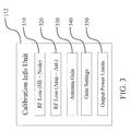
- FIG. 3 is a block diagram illustrating the calibration info unit 112.
- the unit 112 stores data relating to RF loss 310 and 320, antenna gain 330, and gain settings 340 for the amplifiers 106 and 152. This data is stored/updated in the unit 112.
- the unit 112 may also include output power limits 350, which are the limits for input power to each amplifier 106 and 152. That is, the gain settings 340 cannot exceed a level that would cause input power at each amplifier to exceed input power limits 350.
- the RF losses at each frequency from the Head End System Controller (Head End) to the Coverage Nodes is measured in both directions by measuring the output power from the Head End and comparing that to the input power on the Coverage Node for the downlink cable loss, and vice-versa for the uplink cable loss.
- the RF loss from the amplifier to each of the antennas is calculated from the material used to install each antenna (for example, the cable type, cable length, and splitters used), and the gain of each antenna is determined from the antenna specification.
- the downlink (DL) signal strength of cellular and PCS measured at the donor antenna will determine the final configuration (these signal strengths can be measured at the Head End by using the net gain of the cable and donor antenna).
- the above results allow for maximum margin so that any short-term changes in the RF conditions will still operate within the range of the amplifiers. If the RF conditions change outside of the range, then the calibration will be performed again.
- the characterization unit 114 will determine a change outside of margins (e.g., 10dB) and cause the spectrum analyzer to recalculate RF losses, etc. and adjust gains to compensate.
- This system calibration is key to delivering an effective DAS that is easy to install (i.e., the settings are all automated) and the system maintains optimal operation over time.
- the remote connect unit 116 can notify an operator to manually adjust settings when the characterization unit 114 determines a change.
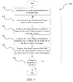
- FIG. 4 is a flowchart illustrating a method 400 according to an embodiment.
- RF Losses are measured (410) in both directions between head end and coverage nodes.
- gain and output power limits are generated (420) and optionally stored in the calibration info unit 112 based on the measurements.
- the gains and power limits can be further adjusted (430) based on downlink signal of signals at the donor antenna if needed.
- the unit 112 can also be updated accordingly.
- the method 400 further comprises calculating (440) RF losses based on installation materials and/or antenna gain & adjusting gains and power limits accordingly.
- the unit 112 can also be updated accordingly.
- the method 400 further comprises transmitting (450) a test (Pilot) signal to determine over-the-air signal separation between nodes and adjusting gain and power limits accordingly.
- the unit 112 can also be updated accordingly.
- the method 400 further comprises monitoring (460) changes in measured RF losses.
- the characterization unit 114 can cause the pilot Tx unit 104 to transmit signals to the nodes 150 and vice versa.
- the characterization unit 114 can then compare RF losses from a prior characterization with the current characterization and adjust the gains and power limits accordingly. Otherwise, the method 400 ends.
Claims (13)
- Verfahren, umfassend:Messen von HF-Verlusten auf mehreren Frequenzen in einer ersten Richtung zwischen einer Kopfstelle und einem Funkversorgungsknoten an einem Standort durch Messung der Ausgangsleistung der Kopfstelle und deren Vergleich mit der Eingangsleistung an einer Mehrzahl von Funkversorgungsknoten, wie aus den Funkversorgungsknoten empfangen, zur Ermittlung des Downlink-Verlusts;Erzeugen von Verstärkungen und Ausgangsleistungsgrenzwerten für jeden Verstärker in jedem Funkversorgungsknoten und der Kopfstelle auf der Grundlage der gemessenen HF-Verluste; undweiteres Abgleichen der erzeugten Verstärkungen und Ausgangsleistungsgrenzwerte auf der Grundlage der Downlink-Signalstärke von Mobilfunksignalen an einer Geberantenne;wobei das Messen das Messen des HF-Verlusts an sowohl einer Geberantenne in der Kopfstelle als auch an Funkversorgungsantennen in den Funkversorgungsknoten einschließt.
- Verfahren nach Anspruch 1, ferner umfassend:Berechnen des HF-Verlusts von jedem Verstärker zu jeder Antenne in dem System auf der Grundlage von Antenneninstallationsmaterialien und des Antennengewinns; undweiteres Abgleichen der erzeugten Verstärkungen und Ausgangsleistungsgrenzwerte für jeden Funkversorgungsknoten auf der Grundlage der berechneten HF-Verluste.
- Verfahren nach Anspruch 1, ferner umfassend:Senden eines Prüfsignals zur Bestimmung der Drahtlossignaltrennung zwischen den mehreren Funkversorgungsknoten; undweiteres Abgleichen der erzeugten Verstärkungen und Ausgangsleistung auf der Grundlage der Bestimmung.
- Verfahren nach Anspruch 1, ferner umfassend:Überwachen der gemessenen HF-Verluste im Verlauf der Zeit; undweiteres Abgleichen der erzeugten Verstärkungen und Ausgangsleistung auf der Grundlage der Überwachung.
- Verfahren nach Anspruch 1, ferner umfassend:Messen von HF-Verlusten auf mehreren Frequenzen in einer zweiten Richtung zwischen einer Kopfstelle und einem Funkversorgungsknoten an einem Standort durch Empfangen der gemessenen Ausgangsleistung von den Knoten und deren Vergleich mit der Eingangsleistung an einer Kopfstelle zur Ermittlung des Uplink-Verlusts;Erzeugen von Verstärkungen und Ausgangsleistungsgrenzwerten für jeden Verstärker in jedem Funkversorgungsknoten und der Kopfstelle auf der Grundlage der gemessenen HF-Verluste; undweiteres Abgleichen der erzeugten Verstärkungen und Ausgangsleistungsgrenzwerte auf der Grundlage der Downlink-Signalstärke von Mobilfunksignalen an einer Geberantenne.
- Verteiltes Verstärkersystem, umfassend:eine Kopfstelle, undeine Mehrzahl von Funkversorgungsknoten, die an einem Standort verteilt und kommunikativ an die Kopfstelle gekoppelt sind;wobei jeder Funkversorgungsknoten einen Verstärker einschließt und die Kopfstelle einen Verstärker einschließt;
wobei der Kopfstellenverstärker so konfiguriert ist, dass er
HF-Verluste auf mehreren Frequenzen in einer ersten Richtung zwischen der Kopfstelle und den Funkversorgungsknoten misst durch Messung der Ausgangsleistung der Kopfstelle und deren Vergleich mit der Eingangsleistung an einer Mehrzahl von Funkversorgungsknoten, wie aus den Funkversorgungsknoten empfangen, zur Ermittlung des Downlink-Verlusts;
Verstärkungen und Ausgangsleistungsgrenzwerte für jeden Verstärker in jedem Funkversorgungsknoten und der Kopfstelle auf der Grundlage der gemessenen HF-Verluste erzeugt; und
die erzeugten Verstärkungen und Ausgangsleistungsgrenzwerte auf der Grundlage der Downlink-Signalstärke von Mobilfunksignalen an einer Geberantenne weiter abgleicht;
wobei das Messen das Messen des HF-Verlusts an sowohl einer Geberantenne in der Kopfstelle als auch an Funkversorgungsantennen in den Funkversorgungsknoten einschließt. - System nach Anspruch 6, wobei der Kopfstellenverstärker ferner so konfiguriert ist, dass er:den HF-Verlust von jedem Verstärker zu jeder Antenne in dem System auf der Grundlage von Antenneninstallationsmaterialien und des Antennengewinns berechnet; unddie erzeugten Verstärkungen und Ausgangsleistungsgrenzwerte für jeden Funkversorgungsknoten auf der Grundlage der berechneten HF-Verluste weiter abgleicht.
- System nach Anspruch 6, ferner umfassend eine Pilot-Tx-Einheit, die so konfiguriert ist, dass sie:ein Prüfsignal zur Bestimmung der Drahtlossignaltrennung zwischen den mehreren Funkversorgungsknoten sendet; undwobei der Verstärker ferner so konfiguriert ist, dass er die erzeugte/n Verstärkungen und Ausgangsleistung auf der Grundlage der Bestimmung abgleicht.
- System nach Anspruch 6, ferner umfassend eine Charakterisierungseinheit, die so konfiguriert ist, dass sie die gemessenen HF-Verluste im Verlauf der Zeit überwacht, und wobei der Kopfstellenverstärker ferner so konfiguriert ist, dass er die erzeugte/n Verstärkungen und Ausgangsleistung auf der Grundlage der Überwachung abgleicht.
- Kopfstelle, umfassend:ein Modem, das so konfiguriert ist, dass es sich kommunikativ an eine Mehrzahl von an einem Standort verteilten Knoten koppelt; undeinen Verstärker;wobei jeder Funkversorgungsknoten einen Verstärker einschließt;
wobei der Kopfstellenverstärker so konfiguriert ist, dass er
HF-Verluste auf mehreren Frequenzen in einer ersten Richtung zwischen der Kopfstelle und den Funkversorgungsknoten misst durch Messung der Ausgangsleistung der Kopfstelle und deren Vergleich mit der Eingangsleistung an einer Mehrzahl von Funkversorgungsknoten, wie aus den Funkversorgungsknoten über das Modem empfangen, zur Ermittlung des Downlink-Verlusts;
Verstärkungen und Ausgangsleistungsgrenzwerte für jeden Verstärker in jedem Funkversorgungsknoten und der Kopfstelle auf der Grundlage der gemessenen HF-Verluste erzeugt; und
die erzeugten Verstärkungen und Ausgangsleistungsgrenzwerte auf der Grundlage der Downlink-Signalstärke von Mobilfunksignalen an einer Geberantenne weiter abgleicht;
wobei das Messen das Messen des HF-Verlusts an sowohl einer Geberantenne in der Kopfstelle als auch an Funkversorgungsantennen in den Funkversorgungsknoten einschließt. - Kopfstelle nach Anspruch 10, wobei der Kopfstellenverstärker ferner so konfiguriert ist, dass er:den HF-Verlust von jedem Verstärker zu jeder Antenne in dem System auf der Grundlage von Antenneninstallationsmaterialien und des Antennengewinns berechnet; unddie erzeugten Verstärkungen und Ausgangsleistungsgrenzwerte für jeden Funkversorgungsknoten auf der Grundlage der berechneten HF-Verluste weiter abgleicht.
- Kopfstelle nach Anspruch 10, ferner umfassend eine Pilot-Tx-Einheit, die so konfiguriert ist, dass sie:ein Prüfsignal zur Bestimmung der Drahtlossignaltrennung zwischen den mehreren Funkversorgungsknoten sendet; undwobei der Verstärker ferner so konfiguriert ist, dass er die erzeugte/n Verstärkungen und Ausgangsleistung auf der Grundlage der Bestimmung abgleicht.
- Kopfstelle nach Anspruch 10, ferner umfassend eine Charakterisierungseinheit, die so konfiguriert ist, dass sie die gemessenen HF-Verluste im Verlauf der Zeit überwacht, und wobei der Kopfstellenverstärker ferner so konfiguriert ist, dass er die erzeugte/n Verstärkungen und Ausgangsleistung auf der Grundlage der Überwachung abgleicht.
Applications Claiming Priority (2)
| Application Number | Priority Date | Filing Date | Title |
|---|---|---|---|
| US201361749922P | 2013-01-08 | 2013-01-08 | |
| PCT/US2014/010568 WO2014110060A1 (en) | 2013-01-08 | 2014-01-08 | System and method for calibration of a distributed amplifier system |
Publications (2)
| Publication Number | Publication Date |
|---|---|
| EP2944157A1 EP2944157A1 (de) | 2015-11-18 |
| EP2944157B1 true EP2944157B1 (de) | 2016-08-24 |
Family
ID=50030498
Family Applications (2)
| Application Number | Title | Priority Date | Filing Date |
|---|---|---|---|
| EP14703949.9A Not-in-force EP2944157B1 (de) | 2013-01-08 | 2014-01-08 | System und verfahren zur kalibrierung eines verteilten verstärkersystems |
| EP14703948.1A Withdrawn EP2944131A1 (de) | 2013-01-08 | 2014-01-08 | System, vorrichtung und verfahren zur einstellung der signalstärke in einem verteilten verstärkersystem |
Family Applications After (1)
| Application Number | Title | Priority Date | Filing Date |
|---|---|---|---|
| EP14703948.1A Withdrawn EP2944131A1 (de) | 2013-01-08 | 2014-01-08 | System, vorrichtung und verfahren zur einstellung der signalstärke in einem verteilten verstärkersystem |
Country Status (3)
| Country | Link |
|---|---|
| US (4) | US9832739B2 (de) |
| EP (2) | EP2944157B1 (de) |
| WO (3) | WO2014110061A1 (de) |
Families Citing this family (17)
| Publication number | Priority date | Publication date | Assignee | Title |
|---|---|---|---|---|
| WO2010090999A1 (en) | 2009-02-03 | 2010-08-12 | Corning Cable Systems Llc | Optical fiber-based distributed antenna systems, components, and related methods for monitoring and configuring thereof |
| US9673904B2 (en) | 2009-02-03 | 2017-06-06 | Corning Optical Communications LLC | Optical fiber-based distributed antenna systems, components, and related methods for calibration thereof |
| US8280259B2 (en) | 2009-11-13 | 2012-10-02 | Corning Cable Systems Llc | Radio-over-fiber (RoF) system for protocol-independent wired and/or wireless communication |
| US9252874B2 (en) | 2010-10-13 | 2016-02-02 | Ccs Technology, Inc | Power management for remote antenna units in distributed antenna systems |
| CN103609146B (zh) | 2011-04-29 | 2017-05-31 | 康宁光缆系统有限责任公司 | 用于增加分布式天线系统中的射频(rf)功率的系统、方法和装置 |
| EP2702710A4 (de) | 2011-04-29 | 2014-10-29 | Corning Cable Sys Llc | Bestimmung der weiterleitungsverzögerung von kommunikationen in verteilten antennensystemen sowie entsprechende komponenten, systeme und verfahren |
| EP2842245A1 (de) | 2012-04-25 | 2015-03-04 | Corning Optical Communications LLC | Verteilte antennensystemarchitekturen |
| KR102069543B1 (ko) * | 2014-10-14 | 2020-01-23 | 주식회사 쏠리드 | 분산 안테나 시스템의 헤드엔드 장치 및 그 신호 처리 방법 |
| US9681313B2 (en) * | 2015-04-15 | 2017-06-13 | Corning Optical Communications Wireless Ltd | Optimizing remote antenna unit performance using an alternative data channel |
| US9948349B2 (en) | 2015-07-17 | 2018-04-17 | Corning Optical Communications Wireless Ltd | IOT automation and data collection system |
| CN105451321B (zh) * | 2015-12-01 | 2019-06-04 | 小米科技有限责任公司 | 提升wifi信号强度的方法、装置及设备 |
| US10225024B2 (en) * | 2016-06-28 | 2019-03-05 | R & D Microwaves, LLC | Antenna |
| CN109792290A (zh) | 2016-10-07 | 2019-05-21 | 威尔逊电子有限责任公司 | 用于无线通信系统的多放大器转发器 |
| US10581484B2 (en) | 2017-10-16 | 2020-03-03 | Cellphone-Mate, Inc. | Signal boosters with compensation for cable loss |
| US11711703B2 (en) * | 2019-12-03 | 2023-07-25 | Fiplex Communications, Inc. | Antenna monitoring system for distributed antenna systems |
| CN113411411B (zh) * | 2021-08-19 | 2021-11-09 | 三维通信股份有限公司 | 设备组网方法、系统、电子装置和存储介质 |
| CN115086988B (zh) * | 2022-03-05 | 2024-02-20 | 广州市瀚云信息技术有限公司 | 一种5g变频系统的无源网络损耗校准方法 |
Family Cites Families (42)
| Publication number | Priority date | Publication date | Assignee | Title |
|---|---|---|---|---|
| DE3685355D1 (de) | 1985-03-29 | 1992-06-25 | Honeywell Inc | Breitband-verstaerker/-mischgeraet. |
| ATA300485A (de) * | 1985-10-17 | 1991-05-15 | Siemens Ag Oesterreich | Einrichtung zur ueberwachung einer schaltstelle fuer die zeitmultiplexe zusammenfuegung mehrerer nachrichtenkanaele fuer digitalsignale, insbesondere fuer pulscodemodulierte signale |
| US5187803A (en) | 1990-01-18 | 1993-02-16 | Andrew Corporation | Regenerative rf bi-directional amplifier system |
| US5752164A (en) | 1992-04-27 | 1998-05-12 | American Pcs L.P. | Autonomous remote measurement unit for a personal communications service system |
| US5627879A (en) | 1992-09-17 | 1997-05-06 | Adc Telecommunications, Inc. | Cellular communications system with centralized base stations and distributed antenna units |
| JP2576769B2 (ja) * | 1993-09-24 | 1997-01-29 | 日本電気株式会社 | 地域無線通信システム |
| DE69625748T2 (de) * | 1995-06-21 | 2003-06-26 | Nec Corp | Kabeldämpfungsentzerrereinrichtung zur Anwendung in einer Funkkommunikationsanlage |
| US5873048A (en) * | 1995-07-27 | 1999-02-16 | Lucent Technologies Inc. | Locator and method for a wireless communication system |
| US6151480A (en) | 1997-06-27 | 2000-11-21 | Adc Telecommunications, Inc. | System and method for distributing RF signals over power lines within a substantially closed environment |
| US6349200B1 (en) | 1997-12-24 | 2002-02-19 | Transcept, Inc. | Monitoring and command system for transceivers used to inter-connect wireless telephones to a broadband network |
| IL137078A (en) | 1999-07-20 | 2005-05-17 | Andrew Corp | Side-to-side repeater and adaptive cancellation for repeater |
| US7558553B1 (en) | 2000-12-21 | 2009-07-07 | Cisco Technology, Inc. | Advance signaling for multi-stage tranceivers |
| US7082320B2 (en) * | 2001-09-04 | 2006-07-25 | Telefonaktiebolaget Lm Ericsson (Publ) | Integration of wireless LAN and cellular distributed antenna |
| US7460831B2 (en) * | 2002-06-20 | 2008-12-02 | Dekolink Wireless Ltd. | System and method for excluding narrow band noise from a communication channel |
| US7009573B2 (en) | 2003-02-10 | 2006-03-07 | Calamp Corp. | Compact bidirectional repeaters for wireless communication systems |
| US7555261B2 (en) * | 2003-03-04 | 2009-06-30 | O'neill Frank P | Repeater system for strong signal environments |
| US7498883B2 (en) | 2005-10-07 | 2009-03-03 | University Of Rochester | Distributed amplifier with built-in filtering functions |
| US20070099667A1 (en) * | 2005-10-28 | 2007-05-03 | P.G. Electronics Ltd. | In-building wireless enhancement system for high-rise with emergency backup mode of operation |
| US8284713B2 (en) | 2006-02-10 | 2012-10-09 | Cisco Technology, Inc. | Wireless audio systems and related methods |
| US8619847B1 (en) * | 2006-11-24 | 2013-12-31 | Altera Corporation | Reconditioning equalizer filter for non-constant envelop signals |
| US20080175175A1 (en) * | 2007-01-18 | 2008-07-24 | Yair Oren | Hybrid Passive Active Broadband Antenna for a Distributed Antenna System |
| US7764924B1 (en) | 2007-05-25 | 2010-07-27 | Sprint Spectrum L.P. | Method and system for repeater shutdown based on received power |
| US9112547B2 (en) | 2007-08-31 | 2015-08-18 | Adc Telecommunications, Inc. | System for and method of configuring distributed antenna communications system |
| US8175649B2 (en) | 2008-06-20 | 2012-05-08 | Corning Mobileaccess Ltd | Method and system for real time control of an active antenna over a distributed antenna system |
| US8085869B2 (en) | 2008-02-14 | 2011-12-27 | Broadcom Corporation | Configurable load impedance for power amplifier predistortion calibration |
| US8219074B2 (en) | 2008-06-12 | 2012-07-10 | Telefonaktiebolaget L M Ericsson (Publ) | Method and apparatus for communication site planning |
| EP2159933B1 (de) | 2008-08-28 | 2013-03-27 | Alcatel Lucent | Verstärkerregelung in einem verteilten Antennensystem |
| EP2394379B1 (de) | 2009-02-03 | 2016-12-28 | Corning Optical Communications LLC | Verteilte antennensysteme auf glasfaserbasis, bestandteile und entsprechende verfahren zu ihrer kalibrierung |
| WO2010124297A1 (en) | 2009-04-24 | 2010-10-28 | Dali Systems Co.Ltd. | Remotely reconfigurable power amplifier system and method |
| US8442515B2 (en) | 2009-11-19 | 2013-05-14 | Kentrox, Inc. | Management system for monitoring and controlling remote sites and equipment |
| GB2476252B (en) | 2009-12-17 | 2012-10-24 | Socowave Technologies Ltd | Communication unit, integrated circuit and method of diverse polarisation |
| US20110150050A1 (en) | 2009-12-23 | 2011-06-23 | Hafedh Trigui | Digital integrated antenna array for enhancing coverage and capacity of a wireless network |
| US9020555B2 (en) | 2010-04-05 | 2015-04-28 | Intel Corporation | System and method for performance enhancement in heterogeneous wireless access network employing distributed antenna system |
| EP3481114B1 (de) | 2010-06-09 | 2022-11-23 | CommScope Technologies LLC | Uplink-rauschminimierung |
| WO2012003860A1 (en) | 2010-07-06 | 2012-01-12 | Telefonaktiebolaget Lm Ericsson (Publ) | Method and arrangement for reducing interference and enhancing coverage |
| EP4319477A3 (de) | 2010-08-17 | 2024-04-17 | Dali Systems Co. Ltd. | Daisy-chain-ring aus entfernten einheiten für ein verteiltes antennensystem |
| EP2641415B1 (de) | 2010-11-16 | 2015-01-07 | Telefonaktiebolaget L M Ericsson (publ) | Verfahren und anordnung zum austesten von alternativen antennenkonfigurationen in einem kommunikationsnetzsystem |
| US8532566B2 (en) * | 2011-06-08 | 2013-09-10 | Andrew Llc | System and method for reducing desensitization of a base station transceiver for mobile wireless repeater systems |
| US9065504B2 (en) | 2011-10-28 | 2015-06-23 | Broadcom Corporation | Transmitter front end with programmable notch filter and methods for use therewith |
| US8254848B1 (en) | 2011-12-09 | 2012-08-28 | At&T Intellectual Property I, Lp | Monitoring system for distributed antenna systems |
| CN102438255B (zh) | 2011-12-30 | 2014-12-24 | 三维通信股份有限公司 | 一种移动通信室内分布监控系统及实现方法 |
| CN103384385A (zh) | 2013-07-17 | 2013-11-06 | 三维通信股份有限公司 | 一种用于分布式天线系统的天馈故障自动检测系统 |
-
2014
- 2014-01-08 EP EP14703949.9A patent/EP2944157B1/de not_active Not-in-force
- 2014-01-08 WO PCT/US2014/010569 patent/WO2014110061A1/en active Application Filing
- 2014-01-08 US US14/149,824 patent/US9832739B2/en not_active Expired - Fee Related
- 2014-01-08 US US14/149,830 patent/US9526075B2/en not_active Expired - Fee Related
- 2014-01-08 WO PCT/US2014/010567 patent/WO2014110059A1/en active Application Filing
- 2014-01-08 WO PCT/US2014/010568 patent/WO2014110060A1/en active Application Filing
- 2014-01-08 US US14/149,832 patent/US20140192849A1/en not_active Abandoned
- 2014-01-08 EP EP14703948.1A patent/EP2944131A1/de not_active Withdrawn
-
2016
- 2016-11-11 US US15/348,982 patent/US20170099639A1/en not_active Abandoned
Also Published As
| Publication number | Publication date |
|---|---|
| US9832739B2 (en) | 2017-11-28 |
| US20140192849A1 (en) | 2014-07-10 |
| EP2944157A1 (de) | 2015-11-18 |
| WO2014110060A1 (en) | 2014-07-17 |
| EP2944131A1 (de) | 2015-11-18 |
| US20170099639A1 (en) | 2017-04-06 |
| WO2014110061A1 (en) | 2014-07-17 |
| US20140192911A1 (en) | 2014-07-10 |
| US9526075B2 (en) | 2016-12-20 |
| US20140194135A1 (en) | 2014-07-10 |
| WO2014110059A1 (en) | 2014-07-17 |
Similar Documents
| Publication | Publication Date | Title |
|---|---|---|
| EP2944157B1 (de) | System und verfahren zur kalibrierung eines verteilten verstärkersystems | |
| EP2025179B1 (de) | System und verfahren zur übertragung von analogen multiband-rf-signalen | |
| US7643791B2 (en) | Method and apparatus for optimizing signal processing | |
| WO2020219152A1 (en) | Methods and apparatuses for automatic filter identification | |
| CN109617625B (zh) | 一种天线间隔离度测量方法 | |
| US7280799B1 (en) | Mobile phone repeater | |
| US20210144537A1 (en) | Combined riser in building emergency repeater system | |
| US7945170B2 (en) | Method and system for optical transmission signal level configuration | |
| US9031496B2 (en) | Apparatus and method for communication satellite monitoring | |
| KR100673171B1 (ko) | 마이크로웨이브 중계기 시스템 및 마이크로웨이브 중계기시스템의 가시선 설정 방법 | |
| US20070298722A1 (en) | Method and system for detecting change in attributes of RF board in base station | |
| US20230292253A1 (en) | Gain autotune | |
| JP4971332B2 (ja) | 無線中継装置 | |
| KR20090029060A (ko) | 광 중계기 게인 자동 세팅 및 불요파 검출 방법 및 장치 | |
| US11601103B2 (en) | Channelised gain control of line amplifiers | |
| KR101495113B1 (ko) | 디지털 게인 자동컨트롤 방법 | |
| CN106973395B (zh) | 链路校准的方法和装置、及射频馈入系统 | |
| CN104052422A (zh) | 确定无线网络内的升压放大器的振荡放大裕度的方法 | |
| US8295774B1 (en) | Methods and apparatuses for providing a stable wideband noise signal | |
| KR20090063853A (ko) | 중계기 역방향 이득 조절 시스템, 및 방법 | |
| KR101826525B1 (ko) | 안테나의 rf 출력분배 감시장치 | |
| JP2003224510A (ja) | 無線通信装置 | |
| CN115333651A (zh) | 数据链系统的接收灵敏度测试系统及其应用方法 | |
| KR100342853B1 (ko) | 지역채널다지점분배서비스 시스템의 성능 측정 장치 및 그방법 | |
| JP2002359579A (ja) | 通信装置におけるケーブル等化方式 |
Legal Events
| Date | Code | Title | Description |
|---|---|---|---|
| PUAI | Public reference made under article 153(3) epc to a published international application that has entered the european phase |
Free format text: ORIGINAL CODE: 0009012 |
|
| 17P | Request for examination filed |
Effective date: 20150717 |
|
| AK | Designated contracting states |
Kind code of ref document: A1 Designated state(s): AL AT BE BG CH CY CZ DE DK EE ES FI FR GB GR HR HU IE IS IT LI LT LU LV MC MK MT NL NO PL PT RO RS SE SI SK SM TR |
|
| AX | Request for extension of the european patent |
Extension state: BA ME |
|
| GRAP | Despatch of communication of intention to grant a patent |
Free format text: ORIGINAL CODE: EPIDOSNIGR1 |
|
| DAX | Request for extension of the european patent (deleted) | ||
| INTG | Intention to grant announced |
Effective date: 20160307 |
|
| GRAS | Grant fee paid |
Free format text: ORIGINAL CODE: EPIDOSNIGR3 |
|
| GRAA | (expected) grant |
Free format text: ORIGINAL CODE: 0009210 |
|
| AK | Designated contracting states |
Kind code of ref document: B1 Designated state(s): AL AT BE BG CH CY CZ DE DK EE ES FI FR GB GR HR HU IE IS IT LI LT LU LV MC MK MT NL NO PL PT RO RS SE SI SK SM TR |
|
| REG | Reference to a national code |
Ref country code: GB Ref legal event code: FG4D |
|
| REG | Reference to a national code |
Ref country code: CH Ref legal event code: EP |
|
| REG | Reference to a national code |
Ref country code: AT Ref legal event code: REF Ref document number: 824072 Country of ref document: AT Kind code of ref document: T Effective date: 20160915 |
|
| REG | Reference to a national code |
Ref country code: IE Ref legal event code: FG4D |
|
| REG | Reference to a national code |
Ref country code: DE Ref legal event code: R096 Ref document number: 602014003285 Country of ref document: DE |
|
| REG | Reference to a national code |
Ref country code: LT Ref legal event code: MG4D |
|
| REG | Reference to a national code |
Ref country code: NL Ref legal event code: MP Effective date: 20160824 |
|
| REG | Reference to a national code |
Ref country code: AT Ref legal event code: MK05 Ref document number: 824072 Country of ref document: AT Kind code of ref document: T Effective date: 20160824 |
|
| REG | Reference to a national code |
Ref country code: FR Ref legal event code: PLFP Year of fee payment: 4 |
|
| PG25 | Lapsed in a contracting state [announced via postgrant information from national office to epo] |
Ref country code: NO Free format text: LAPSE BECAUSE OF FAILURE TO SUBMIT A TRANSLATION OF THE DESCRIPTION OR TO PAY THE FEE WITHIN THE PRESCRIBED TIME-LIMIT Effective date: 20161124 Ref country code: IT Free format text: LAPSE BECAUSE OF FAILURE TO SUBMIT A TRANSLATION OF THE DESCRIPTION OR TO PAY THE FEE WITHIN THE PRESCRIBED TIME-LIMIT Effective date: 20160824 Ref country code: LT Free format text: LAPSE BECAUSE OF FAILURE TO SUBMIT A TRANSLATION OF THE DESCRIPTION OR TO PAY THE FEE WITHIN THE PRESCRIBED TIME-LIMIT Effective date: 20160824 Ref country code: NL Free format text: LAPSE BECAUSE OF FAILURE TO SUBMIT A TRANSLATION OF THE DESCRIPTION OR TO PAY THE FEE WITHIN THE PRESCRIBED TIME-LIMIT Effective date: 20160824 Ref country code: HR Free format text: LAPSE BECAUSE OF FAILURE TO SUBMIT A TRANSLATION OF THE DESCRIPTION OR TO PAY THE FEE WITHIN THE PRESCRIBED TIME-LIMIT Effective date: 20160824 Ref country code: FI Free format text: LAPSE BECAUSE OF FAILURE TO SUBMIT A TRANSLATION OF THE DESCRIPTION OR TO PAY THE FEE WITHIN THE PRESCRIBED TIME-LIMIT Effective date: 20160824 Ref country code: RS Free format text: LAPSE BECAUSE OF FAILURE TO SUBMIT A TRANSLATION OF THE DESCRIPTION OR TO PAY THE FEE WITHIN THE PRESCRIBED TIME-LIMIT Effective date: 20160824 |
|
| PG25 | Lapsed in a contracting state [announced via postgrant information from national office to epo] |
Ref country code: SE Free format text: LAPSE BECAUSE OF FAILURE TO SUBMIT A TRANSLATION OF THE DESCRIPTION OR TO PAY THE FEE WITHIN THE PRESCRIBED TIME-LIMIT Effective date: 20160824 Ref country code: GR Free format text: LAPSE BECAUSE OF FAILURE TO SUBMIT A TRANSLATION OF THE DESCRIPTION OR TO PAY THE FEE WITHIN THE PRESCRIBED TIME-LIMIT Effective date: 20161125 Ref country code: ES Free format text: LAPSE BECAUSE OF FAILURE TO SUBMIT A TRANSLATION OF THE DESCRIPTION OR TO PAY THE FEE WITHIN THE PRESCRIBED TIME-LIMIT Effective date: 20160824 Ref country code: LV Free format text: LAPSE BECAUSE OF FAILURE TO SUBMIT A TRANSLATION OF THE DESCRIPTION OR TO PAY THE FEE WITHIN THE PRESCRIBED TIME-LIMIT Effective date: 20160824 Ref country code: PT Free format text: LAPSE BECAUSE OF FAILURE TO SUBMIT A TRANSLATION OF THE DESCRIPTION OR TO PAY THE FEE WITHIN THE PRESCRIBED TIME-LIMIT Effective date: 20161226 Ref country code: AT Free format text: LAPSE BECAUSE OF FAILURE TO SUBMIT A TRANSLATION OF THE DESCRIPTION OR TO PAY THE FEE WITHIN THE PRESCRIBED TIME-LIMIT Effective date: 20160824 |
|
| PG25 | Lapsed in a contracting state [announced via postgrant information from national office to epo] |
Ref country code: EE Free format text: LAPSE BECAUSE OF FAILURE TO SUBMIT A TRANSLATION OF THE DESCRIPTION OR TO PAY THE FEE WITHIN THE PRESCRIBED TIME-LIMIT Effective date: 20160824 Ref country code: RO Free format text: LAPSE BECAUSE OF FAILURE TO SUBMIT A TRANSLATION OF THE DESCRIPTION OR TO PAY THE FEE WITHIN THE PRESCRIBED TIME-LIMIT Effective date: 20160824 |
|
| PGFP | Annual fee paid to national office [announced via postgrant information from national office to epo] |
Ref country code: FR Payment date: 20170124 Year of fee payment: 4 Ref country code: DE Payment date: 20170125 Year of fee payment: 4 |
|
| REG | Reference to a national code |
Ref country code: DE Ref legal event code: R097 Ref document number: 602014003285 Country of ref document: DE |
|
| PG25 | Lapsed in a contracting state [announced via postgrant information from national office to epo] |
Ref country code: SK Free format text: LAPSE BECAUSE OF FAILURE TO SUBMIT A TRANSLATION OF THE DESCRIPTION OR TO PAY THE FEE WITHIN THE PRESCRIBED TIME-LIMIT Effective date: 20160824 Ref country code: CZ Free format text: LAPSE BECAUSE OF FAILURE TO SUBMIT A TRANSLATION OF THE DESCRIPTION OR TO PAY THE FEE WITHIN THE PRESCRIBED TIME-LIMIT Effective date: 20160824 Ref country code: PL Free format text: LAPSE BECAUSE OF FAILURE TO SUBMIT A TRANSLATION OF THE DESCRIPTION OR TO PAY THE FEE WITHIN THE PRESCRIBED TIME-LIMIT Effective date: 20160824 Ref country code: DK Free format text: LAPSE BECAUSE OF FAILURE TO SUBMIT A TRANSLATION OF THE DESCRIPTION OR TO PAY THE FEE WITHIN THE PRESCRIBED TIME-LIMIT Effective date: 20160824 Ref country code: BE Free format text: LAPSE BECAUSE OF FAILURE TO SUBMIT A TRANSLATION OF THE DESCRIPTION OR TO PAY THE FEE WITHIN THE PRESCRIBED TIME-LIMIT Effective date: 20160824 Ref country code: BG Free format text: LAPSE BECAUSE OF FAILURE TO SUBMIT A TRANSLATION OF THE DESCRIPTION OR TO PAY THE FEE WITHIN THE PRESCRIBED TIME-LIMIT Effective date: 20161124 Ref country code: SM Free format text: LAPSE BECAUSE OF FAILURE TO SUBMIT A TRANSLATION OF THE DESCRIPTION OR TO PAY THE FEE WITHIN THE PRESCRIBED TIME-LIMIT Effective date: 20160824 |
|
| PLBE | No opposition filed within time limit |
Free format text: ORIGINAL CODE: 0009261 |
|
| STAA | Information on the status of an ep patent application or granted ep patent |
Free format text: STATUS: NO OPPOSITION FILED WITHIN TIME LIMIT |
|
| 26N | No opposition filed |
Effective date: 20170526 |
|
| PG25 | Lapsed in a contracting state [announced via postgrant information from national office to epo] |
Ref country code: SI Free format text: LAPSE BECAUSE OF FAILURE TO SUBMIT A TRANSLATION OF THE DESCRIPTION OR TO PAY THE FEE WITHIN THE PRESCRIBED TIME-LIMIT Effective date: 20160824 |
|
| REG | Reference to a national code |
Ref country code: CH Ref legal event code: PL |
|
| PG25 | Lapsed in a contracting state [announced via postgrant information from national office to epo] |
Ref country code: MC Free format text: LAPSE BECAUSE OF FAILURE TO SUBMIT A TRANSLATION OF THE DESCRIPTION OR TO PAY THE FEE WITHIN THE PRESCRIBED TIME-LIMIT Effective date: 20160824 |
|
| PG25 | Lapsed in a contracting state [announced via postgrant information from national office to epo] |
Ref country code: CH Free format text: LAPSE BECAUSE OF NON-PAYMENT OF DUE FEES Effective date: 20170131 Ref country code: LI Free format text: LAPSE BECAUSE OF NON-PAYMENT OF DUE FEES Effective date: 20170131 |
|
| REG | Reference to a national code |
Ref country code: IE Ref legal event code: MM4A |
|
| PG25 | Lapsed in a contracting state [announced via postgrant information from national office to epo] |
Ref country code: LU Free format text: LAPSE BECAUSE OF NON-PAYMENT OF DUE FEES Effective date: 20170108 |
|
| PG25 | Lapsed in a contracting state [announced via postgrant information from national office to epo] |
Ref country code: IE Free format text: LAPSE BECAUSE OF NON-PAYMENT OF DUE FEES Effective date: 20170108 |
|
| REG | Reference to a national code |
Ref country code: DE Ref legal event code: R119 Ref document number: 602014003285 Country of ref document: DE |
|
| GBPC | Gb: european patent ceased through non-payment of renewal fee |
Effective date: 20180108 |
|
| PG25 | Lapsed in a contracting state [announced via postgrant information from national office to epo] |
Ref country code: MT Free format text: LAPSE BECAUSE OF NON-PAYMENT OF DUE FEES Effective date: 20170108 |
|
| PG25 | Lapsed in a contracting state [announced via postgrant information from national office to epo] |
Ref country code: FR Free format text: LAPSE BECAUSE OF NON-PAYMENT OF DUE FEES Effective date: 20180131 Ref country code: DE Free format text: LAPSE BECAUSE OF NON-PAYMENT OF DUE FEES Effective date: 20180801 Ref country code: AL Free format text: LAPSE BECAUSE OF FAILURE TO SUBMIT A TRANSLATION OF THE DESCRIPTION OR TO PAY THE FEE WITHIN THE PRESCRIBED TIME-LIMIT Effective date: 20160824 |
|
| REG | Reference to a national code |
Ref country code: FR Ref legal event code: ST Effective date: 20180928 |
|
| PG25 | Lapsed in a contracting state [announced via postgrant information from national office to epo] |
Ref country code: GB Free format text: LAPSE BECAUSE OF NON-PAYMENT OF DUE FEES Effective date: 20180108 |
|
| PG25 | Lapsed in a contracting state [announced via postgrant information from national office to epo] |
Ref country code: HU Free format text: LAPSE BECAUSE OF FAILURE TO SUBMIT A TRANSLATION OF THE DESCRIPTION OR TO PAY THE FEE WITHIN THE PRESCRIBED TIME-LIMIT; INVALID AB INITIO Effective date: 20140108 |
|
| PG25 | Lapsed in a contracting state [announced via postgrant information from national office to epo] |
Ref country code: CY Free format text: LAPSE BECAUSE OF FAILURE TO SUBMIT A TRANSLATION OF THE DESCRIPTION OR TO PAY THE FEE WITHIN THE PRESCRIBED TIME-LIMIT Effective date: 20160824 |
|
| PG25 | Lapsed in a contracting state [announced via postgrant information from national office to epo] |
Ref country code: MK Free format text: LAPSE BECAUSE OF FAILURE TO SUBMIT A TRANSLATION OF THE DESCRIPTION OR TO PAY THE FEE WITHIN THE PRESCRIBED TIME-LIMIT Effective date: 20160824 |
|
| PG25 | Lapsed in a contracting state [announced via postgrant information from national office to epo] |
Ref country code: TR Free format text: LAPSE BECAUSE OF FAILURE TO SUBMIT A TRANSLATION OF THE DESCRIPTION OR TO PAY THE FEE WITHIN THE PRESCRIBED TIME-LIMIT Effective date: 20160824 |
|
| PG25 | Lapsed in a contracting state [announced via postgrant information from national office to epo] |
Ref country code: IS Free format text: LAPSE BECAUSE OF FAILURE TO SUBMIT A TRANSLATION OF THE DESCRIPTION OR TO PAY THE FEE WITHIN THE PRESCRIBED TIME-LIMIT Effective date: 20161224 |