EP2944105B1 - Systems and methods for formatting frames in neighborhood aware networks - Google Patents
Systems and methods for formatting frames in neighborhood aware networks Download PDFInfo
- Publication number
- EP2944105B1 EP2944105B1 EP13821030.7A EP13821030A EP2944105B1 EP 2944105 B1 EP2944105 B1 EP 2944105B1 EP 13821030 A EP13821030 A EP 13821030A EP 2944105 B1 EP2944105 B1 EP 2944105B1
- Authority
- EP
- European Patent Office
- Prior art keywords
- field
- nan
- discovery
- beacon
- address
- Prior art date
- Legal status (The legal status is an assumption and is not a legal conclusion. Google has not performed a legal analysis and makes no representation as to the accuracy of the status listed.)
- Active
Links
- 238000000034 method Methods 0.000 title claims description 56
- 239000000523 sample Substances 0.000 claims description 14
- 230000004044 response Effects 0.000 claims description 12
- 238000004590 computer program Methods 0.000 claims description 4
- 238000004891 communication Methods 0.000 description 63
- 230000005540 biological transmission Effects 0.000 description 17
- 230000006870 function Effects 0.000 description 12
- 238000012545 processing Methods 0.000 description 10
- 230000008569 process Effects 0.000 description 8
- 230000009471 action Effects 0.000 description 7
- 238000007726 management method Methods 0.000 description 6
- 230000006855 networking Effects 0.000 description 6
- 230000003287 optical effect Effects 0.000 description 6
- 230000008901 benefit Effects 0.000 description 3
- 238000004422 calculation algorithm Methods 0.000 description 3
- 238000013461 design Methods 0.000 description 3
- 238000005516 engineering process Methods 0.000 description 3
- 230000001413 cellular effect Effects 0.000 description 2
- 230000004048 modification Effects 0.000 description 2
- 238000012986 modification Methods 0.000 description 2
- 239000002245 particle Substances 0.000 description 2
- 238000000926 separation method Methods 0.000 description 2
- 238000013459 approach Methods 0.000 description 1
- 238000004364 calculation method Methods 0.000 description 1
- 230000001419 dependent effect Effects 0.000 description 1
- 238000010586 diagram Methods 0.000 description 1
- 238000001914 filtration Methods 0.000 description 1
- 230000000977 initiatory effect Effects 0.000 description 1
- 230000007246 mechanism Effects 0.000 description 1
- 230000008520 organization Effects 0.000 description 1
- 230000003595 spectral effect Effects 0.000 description 1
- 230000001360 synchronised effect Effects 0.000 description 1
- 238000012546 transfer Methods 0.000 description 1
Images


Classifications
-
- H—ELECTRICITY
- H04—ELECTRIC COMMUNICATION TECHNIQUE
- H04L—TRANSMISSION OF DIGITAL INFORMATION, e.g. TELEGRAPHIC COMMUNICATION
- H04L67/00—Network arrangements or protocols for supporting network services or applications
- H04L67/50—Network services
- H04L67/51—Discovery or management thereof, e.g. service location protocol [SLP] or web services
-
- H—ELECTRICITY
- H04—ELECTRIC COMMUNICATION TECHNIQUE
- H04W—WIRELESS COMMUNICATION NETWORKS
- H04W48/00—Access restriction; Network selection; Access point selection
- H04W48/18—Selecting a network or a communication service
-
- H—ELECTRICITY
- H04—ELECTRIC COMMUNICATION TECHNIQUE
- H04W—WIRELESS COMMUNICATION NETWORKS
- H04W76/00—Connection management
-
- H—ELECTRICITY
- H04—ELECTRIC COMMUNICATION TECHNIQUE
- H04W—WIRELESS COMMUNICATION NETWORKS
- H04W76/00—Connection management
- H04W76/10—Connection setup
-
- H—ELECTRICITY
- H04—ELECTRIC COMMUNICATION TECHNIQUE
- H04W—WIRELESS COMMUNICATION NETWORKS
- H04W8/00—Network data management
- H04W8/005—Discovery of network devices, e.g. terminals
-
- H—ELECTRICITY
- H04—ELECTRIC COMMUNICATION TECHNIQUE
- H04W—WIRELESS COMMUNICATION NETWORKS
- H04W84/00—Network topologies
- H04W84/18—Self-organising networks, e.g. ad-hoc networks or sensor networks
-
- H—ELECTRICITY
- H04—ELECTRIC COMMUNICATION TECHNIQUE
- H04W—WIRELESS COMMUNICATION NETWORKS
- H04W4/00—Services specially adapted for wireless communication networks; Facilities therefor
- H04W4/70—Services for machine-to-machine communication [M2M] or machine type communication [MTC]
-
- H—ELECTRICITY
- H04—ELECTRIC COMMUNICATION TECHNIQUE
- H04W—WIRELESS COMMUNICATION NETWORKS
- H04W4/00—Services specially adapted for wireless communication networks; Facilities therefor
- H04W4/80—Services using short range communication, e.g. near-field communication [NFC], radio-frequency identification [RFID] or low energy communication
Definitions
- the present application relates generally to wireless communications, and more specifically to a system and method for formatting frames in neighborhood aware networks.
- communications networks are used to exchange messages among several interacting spatially-separated devices.
- Networks may be classified according to geographic scope, which may be, for example, a metropolitan area, a local area, or a personal area. Such networks may be designated respectively as a wide area network (WAN), metropolitan area network (MAN), local area network (LAN), wireless local area network (WLAN), or personal area network (PAN).
- WAN wide area network
- MAN metropolitan area network
- LAN local area network
- WLAN wireless local area network
- PAN personal area network
- Networks also differ according to the switching/routing technique used to interconnect the various network nodes and devices (e.g., circuit switching vs. packet switching), the type of physical media employed for transmission (e.g., wired vs. wireless), and the set of communication protocols used (e.g., Internet protocol suite, SONET (Synchronous Optical Networking), Ethernet, etc.).
- SONET Synchronous Optical Networking
- Wireless networks are often preferred when the network elements are mobile and thus have dynamic connectivity needs, or if the network architecture is formed in an ad hoc, rather than fixed, topology.
- Wireless networks employ intangible physical media in an unguided propagation mode using electromagnetic waves in the radio, microwave, infra-red, optical, etc. frequency bands. Wireless networks advantageously facilitate user mobility and rapid field deployment when compared to fixed wired networks.
- the information may include packets, which in some aspects may be referred to as data units or data frames.
- the packets may include overhead information (e.g., header information, packet properties, etc.) that helps in routing the packet through the network, identifying the data in the packet, processing the packet, etc., as well as data, for example user data, multimedia content, etc. as might be carried in a payload of the packet.
- overhead information e.g., header information, packet properties, etc.
- the devices may also broadcast a beacon signal to other nodes to help the nodes synchronize timing or to provide other information or functionality.
- Beacons may therefore convey a large amount of data, some of which may be used by a given node. Accordingly, transmission of data in such beacons may be inefficient due to the fact that much of the bandwidth for transmitting beacons may be used to transmit data that may not be used Thus, improved systems, methods, and devices for communicating packets are desired.
- the US patent application publication US 2007(0286136 ) relates to energy-efficient discovery techniques for a client node to discover at least one peer provider node in an ad hoc network.
- the client node can be configured to turn on its first ad hoc interface while in a discovery mode to establish a channel for a first time period.
- the client node can then transmit a first beacon to advertise its presence to other nodes within the transmission range of the client node to acquire service information from at least one of a plurality of prospective peer provider nodes within the transmission range of the client node.
- At least one of the prospective peer provider nodes is configured to turn on its second ad hoc interface for a second period of time to listen for beacons from other nodes.
- the second period of time is less than or equal to the first period of time.
- US 2011/0153773 A1 relates to efficient service advertisement and discovery in a peer-to-peer networking environment with cooperative advertisement.
- An advertisement request is transmitted from a local device to a remote device based on a comparison of the operating conditions of the local device and the remote device.
- the advertisement request includes information identifying one or more services advertised by the local device, whereby the remote device is configured to advertise the one or more services on behalf of the local device in the wireless network.
- Wi-Fi Peer-to-Peer (P2P) Technical Specification, Version 1.2 discloses a Peer to Peer discovery method, including probe requests and probe responses.
- the method includes determining a discovery period.
- the method further includes generating a discovery window information element indicating a start time of a discovery window.
- the method further includes generating a NAN beacon or other sync frame comprising information identifying the discovery period and the discovery window information element.
- the method further includes transmitting, at a wireless device, the NAN beacon or other sync frame during the discovery window.
- the wireless device configured to communicate in a wireless neighborhood aware network (NAN).
- the wireless device comprises a processor configured to determine a discovery period.
- the processor is further configured to generate a discovery window information element indicating a start time of a discovery window.
- the processor is further configured to generate a NAN beacon or other sync frame comprising information identifying the discovery period and the discovery window information element.
- the processor is further configured to transmit, at a wireless device, the NAN beacon or other sync frame during the discovery window.
- the apparatus includes means for determining a discovery period.
- the apparatus further includes means for generating a discovery window information element indicating a start time of a discovery window.
- the apparatus further includes means for generating a NAN beacon or other sync frame comprising information identifying the discovery period and the discovery window information element.
- the apparatus further includes means for transmitting, at a wireless device, the NAN beacon or other sync frame during the discovery window.
- the medium comprises code that, when executed, causes an apparatus to determine a discovery period.
- the medium further comprises code that, when executed, causes an apparatus to generate a discovery window information element indicating a start time of a discovery window.
- the medium further comprises code that, when executed, causes an apparatus to generate a NAN beacon or other sync frame comprising information identifying the discovery period and the discovery window information element.
- the medium further comprises code that, when executed, causes an apparatus to transmit, at a wireless device, the NAN beacon or other sync frame during the discovery window.
- an apparatus may be implemented or a method may be practiced using any number of the aspects set forth herein.
- the scope of the invention covers such an apparatus or method which is practiced using other structure, functionality, or structure and functionality in addition to or other than the various aspects of the invention set forth herein. Any aspect disclosed herein may be embodied by one or more elements of a claim.
- WLAN wireless local area networks
- a WLAN may be used to interconnect nearby devices together, employing widely used networking protocols.
- the various aspects described herein may apply to any communication standard, such as a wireless protocol.
- a WLAN includes various devices which are the components that access the wireless network.
- access points access points
- STAs stations
- an AP may serve as a hub or base station for the WLAN and a STA serves as a user of the WLAN.
- a STA may be a laptop computer, a personal digital assistant (PDA), a mobile phone, etc.
- PDA personal digital assistant
- a STA connects to an AP via a WiFi (e.g., IEEE 802.11 protocol) compliant wireless link to obtain general connectivity to the Internet or to other wide area networks.
- a STA may also be used as an AP.
- An access point may also comprise, be implemented as, or known as a NodeB, Radio Network Controller (“RNC”), eNodeB, Base Station Controller (“BSC”), Base Transceiver Station (“BTS”), Base Station (“BS”), Transceiver Function (“TF”), Radio Router, Radio Transceiver, or some other terminology.
- RNC Radio Network Controller
- BSC Base Station Controller
- BTS Base Transceiver Station
- BS Base Station
- Transceiver Function TF
- Radio Router Radio Transceiver, or some other terminology.
- a station “STA” may also comprise, be implemented as, or known as an access terminal ("AT”), a subscriber station, a subscriber unit, a mobile station, a remote station, a remote terminal, a user terminal, a user agent, a user device, user equipment, or some other terminology.
- an access terminal may comprise a cellular telephone, a cordless telephone, a Session Initiation Protocol ("SIP”) phone, a wireless local loop (“WLL”) station, a personal digital assistant (“PDA”), a handheld device having wireless connection capability, or some other suitable processing device or wireless device connected to a wireless modem.
- SIP Session Initiation Protocol
- WLL wireless local loop
- PDA personal digital assistant
- a phone e.g., a cellular phone or smartphone
- a computer e.g., a laptop
- a portable communication device e.g., a headset
- a portable computing device e.g., a personal data assistant
- an entertainment device e.g., a music or video device, or a satellite radio
- gaming device or system e.g., a gaming console, a global positioning system device, or any other suitable device that is configured to communicate via a wireless medium.
- Devices such as a group of stations, for example, may be used for neighborhood aware networking (NAN), or social-WiFi networking.
- NAN neighborhood aware networking
- various stations within the network may communicate on a device to device (e.g., peer-to-peer communications) basis with one another regarding applications that each of the stations supports.
- a discovery packet may also be referred to as a discovery message or a discovery frame.
- a paging or query packet may also be referred to as a paging or query message or a paging or query frame.
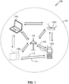
- FIG. 1 illustrates an example of a wireless communication system 100 in which aspects of the present disclosure may be employed.
- the wireless communication system 100 may operate pursuant to a wireless standard, such as an 802.11 standard.
- the wireless communication system 100 may include an AP 104, which communicates with STAs 106.
- the wireless communication system 100 may include more than one AP.
- the STAs 106 may communicate with other STAs 106.
- a first STA 106a may communicate with a second STA 106b.
- a first STA 106a may communicate with a third STA 106c although this communication link is not illustrated in FIG. 1 .
- a variety of processes and methods may be used for transmissions in the wireless communication system 100 between the AP 104 and the STAs 106 and between an individual STA, such as the first STA 106a, and another individual STA, such as the second STA 106b.
- signals may be sent and received in accordance with OFDM/OFDMA techniques. If this is the case, the wireless communication system 100 may be referred to as an OFDM/OFDMA system.
- signals may be sent and received between the AP 104 and the STAs 106 and between an individual STA, such as the first STA 106a, and another individual STA, such as the second STA 106b, in accordance with CDMA techniques. If this is the case, the wireless communication system 100 may be referred to as a CDMA system.
- a communication link that facilitates transmission from the AP 104 to one or more of the STAs 106 may be referred to as a downlink (DL) 108, and a communication link that facilitates transmission from one or more of the STAs 106 to the AP 104 may be referred to as an uplink (UL) 110.
- DL downlink
- UL uplink
- a downlink 108 may be referred to as a forward link or a forward channel
- an uplink 110 may be referred to as a reverse link or a reverse channel.
- a communication link may be established between STAs, such as during social-WiFi networking. Some possible communication links between STAs are illustrated in FIG. 1 . As an example, a communication link 112 may facilitate transmission from the first STA 106a to the second STA 106b. Another communication link 114 may facilitate transmission from the second STA 106b to the first STA 106a.
- the AP 104 may act as a base station and provide wireless communication coverage in a basic service area (BSA) 102.
- BSA basic service area
- the AP 104 along with the STAs 106 associated with the AP 104 and that use the AP 104 for communication may be referred to as a basic service set (BSS).
- BSS basic service set
- the wireless communication system 100 may not have a central AP 104, but rather may function as a peer-to-peer network between the STAs 106. Accordingly, the functions of the AP 104 described herein may alternatively be performed by one or more of the STAs 106.
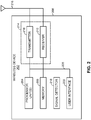
- FIG. 2 illustrates various components that may be utilized in a wireless device 202 that may be employed within the wireless communication system 100.
- the wireless device 202 is an example of a device that may be configured to implement the various methods described herein.
- the wireless device 202 may comprise the AP 104 or one of the STAs 106.
- the wireless device 202 may include a processor 204 which controls operation of the wireless device 202.
- the processor 204 may also be referred to as a central processing unit (CPU).
- Memory 206 which may include both read-only memory (ROM) and random access memory (RAM), may provide instructions and data to the processor 204.
- a portion of the memory 206 may also include non-volatile random access memory (NVRAM).
- the processor 204 may perform logical and arithmetic operations based on program instructions stored within the memory 206.
- the instructions in the memory 206 may be executable to implement the methods described herein.
- the processor 204 may comprise or be a component of a processing system implemented with one or more processors.
- the one or more processors may be implemented with any combination of general-purpose microprocessors, microcontrollers, digital signal processors (DSPs), field programmable gate array (FPGAs), programmable logic devices (PLDs), controllers, state machines, gated logic, discrete hardware components, dedicated hardware finite state machines, or any other suitable entities that may perform calculations or other manipulations of information.
- the processing system may also include machine-readable media for storing software.
- Software shall be construed broadly to mean any type of instructions, whether referred to as software, firmware, middleware, microcode, hardware description language, or otherwise. Instructions may include code (e.g., in source code format, binary code format, executable code format, or any other suitable format of code). The instructions, when executed by the one or more processors, cause the processing system to perform the various functions described herein.
- the wireless device 202 may also include a housing 208 that may include a transmitter 210 and/or a receiver 212 to allow transmission and reception of data between the wireless device 202 and a remote location.
- the transmitter 210 and receiver 212 may be combined into a transceiver 214.
- An antenna 216 may be attached to the housing 208 and electrically coupled to the transceiver 214.
- the wireless device 202 may also include (not shown) multiple transmitters, multiple receivers, multiple transceivers, and/or multiple antennas.
- the transmitter 210 may be configured to wirelessly transmit packets having different packet types or functions.
- the transmitter 210 may be configured to transmit packets of different types generated by the processor 204.
- the processor 204 may be configured to process packets of a plurality of different packet types.
- the processor 204 may be configured to determine the type of packet and to process the packet and/or fields of the packet accordingly.
- the processor 204 may also be configured to select and generate one of a plurality of packet types.
- the processor 204 may be configured to generate a discovery packet comprising a discovery message and to determine what type of packet information to use in a particular instance.
- the receiver 212 may be configured to wirelessly receive packets having different packet types. In some aspects, the receiver 212 may be configured to detect a type of a packet used and to process the packet accordingly.
- the wireless device 202 may also include a signal detector 218 that may be used in an effort to detect and quantify the level of signals received by the transceiver 214.
- the signal detector 218 may detect such signals as total energy, energy per subcarrier per symbol, power spectral density and other signals.
- the wireless device 202 may also include a digital signal processor (DSP) 220 for use in processing signals.
- DSP 220 may be configured to generate a packet for transmission.
- the packet may comprise a physical layer data unit (PPDU).
- PPDU physical layer data unit
- the wireless device 202 may further comprise a user interface 222 in some aspects.
- the user interface 222 may comprise a keypad, a microphone, a speaker, and/or a display.
- the user interface 222 may include any element or component that conveys information to a user of the wireless device 202 and/or receives input from the user.
- the various components of the wireless device 202 may be coupled together by a bus system 226.
- the bus system 226 may include a data bus, for example, as well as a power bus, a control signal bus, and a status signal bus in addition to the data bus.
- the components of the wireless device 202 may be coupled together or accept or provide inputs to each other using some other mechanism.
- processor 204 may be used to implement not only the functionality described above with respect to the processor 204, but also to implement the functionality described above with respect to the signal detector 218 and/or the DSP 220. Further, each of the components illustrated in FIG. 2 may be implemented using a plurality of separate elements.
- the AP 104 or STAs 106 may receive information regarding characteristics of the AP 104 or STAs 106. For example, the STA 106 may use timing information about the AP 104 in order to synchronize timing of communication between the STA 106 and the AP 104. Additionally or alternatively, the STA 106 may require other information such as a medium access control (MAC) address of the AP 104 or another STA, an identifier of the basic service set (BSS) served by the AP 104, etc. The STA 106 may determine whether it needs such information independently, such as through software that is executed using memory 206 and processor 204.
- MAC medium access control
- BSS basic service set
- the AP 104 or STA 106 may have a plurality of operational modes.
- the STA 106 may have a first operational mode referred to as an active mode, normal operation mode, or full power mode.
- the STA 106 may be in an "awake” state and actively transmit/receive data with another STA 106.
- the STA 106 may have a second operational mode referred to as a power-save mode or sleep mode.
- the STA 106 may be in the "awake” state or may be in a "doze” or "sleep” state where the STA 106 does not actively transmit/receive data with another STA 106.
- the receiver 212 and possibly DSP 220 and signal detector 218 of the STA 106 may operate using reduced power consumption in the doze state. Further, in the power-save mode, a STA 106 may occasionally enter the awake state to listen to messages from an AP 104 or from other STAs (e.g., paging messages) that indicate to the STA 106 whether or not the STA 106 needs to "wake up" (e.g., enter the awake state) at a certain time so as to be able to transmit/receive data with the AP 104 or another STA.
- a STA 106 may occasionally enter the awake state to listen to messages from an AP 104 or from other STAs (e.g., paging messages) that indicate to the STA 106 whether or not the STA 106 needs to "wake up" (e.g., enter the awake state) at a certain time so as to be able to transmit/receive data with the AP 104 or another STA.
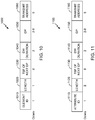
- FIG. 3 illustrates an exemplary communication timeline 300 in a wireless communication system where devices may communicate via one channel.
- the exemplary communication timeline 300 may include a discovery interval (DI) 302 of a time duration ⁇ A 306, a paging interval (PI) 304 of a time duration ⁇ B 308, and an overall interval of a time duration ⁇ C 310.
- DI discovery interval
- PI paging interval
- ⁇ C time duration
- communications may occur via other channels as well. Time increases horizontally across the page over the time axis.
- APs or STAs may advertise services through broadcast messages such as discovery packets.
- the DI 302 may be referred to as a discovery window (DW).
- APs or STAs may listen to broadcast messages transmitted by other APs or STAs.
- the duration of DIs may vary over time. In other aspects, the duration of the DI may remain fixed over a period of time.
- the end of the DI 302 may be separated from the beginning of the subsequent PI 304 by a first remainder period of time as illustrated in FIG. 3 .
- the end of the PI 304 may be separated from the beginning of a subsequent DI by a different remainder period of time as illustrated in FIG. 3 .
- APs or STAs may indicate interest in one or more of a plurality of services advertised in a broadcast message by transmitting paging request messages such as paging request packets.
- APs or STAs may listen to paging request messages transmitted by other APs or STAs.
- the duration of the PI may vary over time. In other aspects, the duration of the PI may remain constant over a period of time. In some aspects, the duration of the PI may be less than the duration of the DI.
- the overall interval of duration ⁇ C 310 may measure the period of time from the beginning of one DI to the beginning of a subsequent DI as illustrated in FIG. 3 .
- the duration ⁇ C 310 may be referred to as a discovery period (DP).
- the duration of the overall interval may vary over time.
- the duration of the overall interval may remain constant over a period of time.
- another overall interval may begin, including a DI, a PI, and the remainder intervals. Consecutive overall intervals may follow indefinitely or continue for a fixed period of time.
- a STA may enter a sleep or power-save mode when the STA is not transmitting or listening or is not expecting to transmit or listen.
- the STA may sleep during periods other than the DI or PI.
- the STA in the sleep mode or power-save mode may awake or return to normal operation or full power mode at the beginning of the DI or PI to enable transmission or listening by the STA.
- the STA may awake or return to normal operation or full power mode at other times when the STA expects to communicate with another device, or as a result of receiving a notification packet instructing the STA to awake.
- the STA may awake early to ensure that the STA receives a transmission.
- APs or STAs may transmit discovery packets (DPs).
- DPs discovery packets
- PRs paging request packets
- a DP may be a packet configured to advertise a plurality of services provided by a STA or AP and to indicate when the paging interval is for the device that transmits the discovery packet.
- the DP may include a data frame, management frame, or management action frame.
- the DP may carry information generated by a higher layer discovery protocol or an application based discovery protocol.
- the PR may be a packet configured to indicate interest in at least one of the plurality of services provided by an AP or STA.
- the start and end of the DI and PI may be known via numerous methods to each STA desiring to transmit a discovery packet or a paging request packet.
- each STA may synchronize its clock with the other APs or STAs and set a shared DI and PI start time and DI duration and PI duration.
- a device may send a signal such as a special clear to send (S-CTS) signal to clear the medium of legacy communications, such as communications that may conflict or not be compliant with aspects of the present disclosure, and indicate the beginning and duration of the DI or PI period, as well as additional information about the DI and PI durations.
- S-CTS special clear to send
- a STA potentially interested in services advertised via discovery packets may awake or remain awake during the DI and process discovery packets to determine if a particular discovery packet includes information about one or more of a plurality of services that may be of interest to the receiving STA.
- STAs not planning to communicate information may enter a sleep or power-save mode for a break period until the next time the STAs plan to communicate.
- a STA may enter the sleep or power-save mode until the STA may communicate additional information with another device outside of the DI or PI.
- the STA may enter the sleep or power-save mode until the beginning of the next PI.
- the interested STA may awake to transmit a paging request packet to the provider of the service.
- a STA waiting for a response to a transmitted discovery packet may awake or remain awake during the PI and process paging request packets to determine if a particular paging request packet indicates interest by another device in at least one of plurality of services provided by the STA.
- STAs not planning to communicate information may enter a sleep or power-save mode for a break period until the next time the STAs plan to communicate.
- a STA may enter the sleep or power-save mode until the STA may communicate additional information with another device outside of the DI or PI.
- the STA may enter the sleep or power-save mode until the beginning of the next DI.
- the duration ⁇ C of the overall interval may equal approximately one to five seconds in some aspects. In other aspects, the overall interval may be less than one second or more than five seconds.
- the duration ⁇ A of the DI may equal approximately 16 ms in some aspects while more or less than 16 ms in other aspects.
- the duration ⁇ B of the PI may equal approximately the duration ⁇ A in some aspects. In other aspects, the duration ⁇ B may be more or less than the duration ⁇ A.
- FIG. 4 illustrates an example of a beacon frame 400 used in legacy systems for communication.
- the beacon 400 includes a median access control (MAC) header 402, a frame body 404, and a frame control sequence (FCS) 406.
- MAC median access control
- FCS frame control sequence
- the MAC header 402 is 24 bytes long
- the frame body 404 is of variable length
- the FCS 406 is four bytes long.
- the MAC header 402 serves to provide basic routing information for the beacon frame 400.
- the MAC header 402 includes a frame control (FC) field 408, a duration field 410, a destination address (DA) field 412, a source address (SA) field 414, a basic service set identification (BSSID) field 416, and a sequence control field 418.
- FC frame control
- DA destination address
- SA source address
- BSSID basic service set identification
- sequence control field 418 is two bytes long.
- the frame body 404 serves to provide detailed information about the transmitting node.
- the frame body 404 includes a timestamp field 420, a beacon interval field 422, a capability information field 424, a service set identifier (SSID) field 426, a supported rates field 428, a frequency-hopping (FH) parameter set 430, a direct-sequence parameter set 432, a contention-free parameter set 434, an independent basic service set (IBSS) parameter set 436, a country information field 438, a FH hopping parameter field 440, a FH pattern table 442, a power constraint field 444, a channel switch announcement field 446, a quiet field 448, a IBSS direct frequency selection (DFS) field 450, a transmit power control (TPC) field 452, an effective radiated power (ERP) information field 454, an extended supported rates field 456, and a robust security network (RSN) field 458.
- a timestamp field 420 includes a timest
- the timestamp field 420 is eight bytes long
- the beacon interval field 422 is two bytes long
- the capability information field 424 is two bytes long
- the service set identifier (SSID) field 426 is a variable length
- the supported rates field 428 is a variable length
- the frequency-hopping (FH) parameter set 430 is seven bytes long
- the direct-sequence parameter set 432 is two bytes long
- the contention-free parameter set 434 is eight bytes long
- an independent basic service set (IBSS) parameter set 436 is 4 bytes long
- the country information field 438 is a variable length
- the FH hopping parameter field 440 is four bytes long
- the FH pattern table 442 is a variable length
- the power constraint field 444 is three bytes long
- the channel switch announcement field 446 is six bytes long
- the quiet field 448 is eight bytes long
- the IBSS direct frequency selection (DFS) field 450 is a variable length
- the beacon frame 400 is a variable length, it may be at least 89 bytes long. In various radio environments, much of the information contained in the beacon frame 400 may be used infrequently or not at all. Accordingly, in low-power radio environments, it may be desirable to reduce the length of the beacon frame 400 in order to reduce power consumption. Moreover, some radio environments use low data rates. For example an access point implementing an 802.11ah standard may take a relatively long time to transmit the beacon frame 400 due to relatively slow data transmission rates. Accordingly, it may be desirable to reduce the length of the beacon frame 400 in order to shorten the amount of time it takes to transmit the beacon frame 400.
- neighborhood aware networks may use a synchronization beacon formatted to be compatible with existing hardware configured to decode the beacon frame 400.
- one or more STAs and/or APs in a neighborhood aware network may transmit a NAN beacon frame, which may be used to maintain synchronization across STAs in the NAN.
- various fields in the beacon frame 400 may be removed, resized, and/or repurposed.
- FIG. 5 illustrates an example neighborhood aware network beacon frame 500.
- the NAN beacon frame 500 includes a frame control (FC) field 508, a duration field 510, a destination address (DA) field 512, a source address (SA) field 514, a NAN BSSID field 516, a sequence control field 518, a high-throughput (HT) control field 519, a timestamp 520, a discovery period field 522, a reserved capability field 524, an SSID field 526, a discovery window (DW) information field 529, and a frame check sequence (FCS) 506.
- FC frame control
- FC duration field 510
- DA destination address
- SA source address
- NAN BSSID field 516 includes a sequence control field 518, a high-throughput (HT) control field 519, a timestamp 520, a discovery period field 522, a reserved capability field 524, an SSID field 526, a discovery window (DW) information field 529, and a
- the frame control (FC) field 508 is 2 bytes long
- the duration field 510 is 2 bytes long
- the destination address (DA) field 512 is 6 bytes long
- the source address (SA) field 514 is 6 bytes long
- the NAN BSSID field 516 is 6 bytes long
- the sequence control field 518 is 2 bytes long
- the high-throughput (HT) control field 519 is 4 bytes long
- the timestamp 520 is 8 bytes long
- the discovery period field 522 is 2 bytes long
- the reserved capability field 524 is 2 bytes long
- an SSID field 526 a variable length
- the discovery window (DW) information field 529 is a variable length
- the frame check sequence (FCS) 506 is 4 bytes long.
- the NAN beacon frame 500 may omit one or more fields shown in FIG. 5 and/or include one or more fields not shown in FIG. 5 , including any of the fields discussed herein.
- the fields in the NAN beacon frame 500 may be of different suitable lengths, and may be in a different order.
- one or more of the frame control (FC) field 508, the duration field 510, the destination address (DA) field 512, the source address (SA) field 514, the sequence control field 518, the timestamp 520, the SSID field 526, and the frame check sequence (FCS) 506 may include the frame control (FC) field 408, the duration field 410, the destination address (DA) field 412, the source address (SA) field 414, the sequence control field 418, the timestamp 420, the SSID field 426, and the frame check sequence (FCS) 406 described above with respect to FIG. 4 , respectively.
- the frame control (FC) field 508, the duration field 510, the destination address (DA) field 512, the source address (SA) field 514, the NAN BSSID field 516, and the sequence control field 518 may be configured to have the same format as a legacy MAC header, such as the MAC header 402 of FIG. 4 .
- the NAN beacon frame 500 may be formatted for processing by legacy hardware, without modification.
- the NAN BSSID field 516 may have the same format as the BSSID field 416 described above with respect to FIG. 4 , but may be interpreted differently.
- the NAN BSSID 516 may include a predetermined or token BSSID, used in all NAN synchronization frames. Accordingly, different networks may include the same NAN BSSID in synchronization frames.
- the token BSSID may be preset, universally known, and/or dynamically determined.
- the DA field 512 may be set to a broadcast address
- the SA field 514 may be set to a sender address.
- each NAN may have a different (for example, pseudorandom) NAN BSSID 516.
- the NAN BSSID 516 may be based on a service application. For example, a NAN created by Application A may have a BSSID 516 based on an identifier of Application A.
- the NAN BSSID 516 may be defined by a standards-body.
- the NAN BSSID 516 may be based on other contextual information and/or device characteristics such as, for example, a device location, a server-assigned ID, etc.
- the NAN BSSID 516 may include a hash of the latitude and longitude location of the NAN.
- the frame control field 508 may include a type indicator.
- the FC 508 type indicator may indicate that the NAN beacon 500 is a management frame.
- a STA 106 FIG. 1
- the type indicator may indicate that the frame is a probe response.
- the timestamp 520 may have the same format as the timestamp 420 described above with respect to FIG. 4 , but may be interpreted differently.
- the timestamp 520 may include the clock time of a transmitting device, at the time of transmission or at the time of frame compilation.
- a STA 106 ( FIG. 1 ) may set the timestamp 520 to an internal clock value.
- the discovery period field 522 may have the same format as the beacon interval field 422 described above with respect to FIG. 4 , but may be interpreted differently.
- the discovery period field 522 may indicate a length of the discovery period 310 (described above with respect to FIG. 3 ).
- the timestamp 520 may indicate when the discovery interval 302 may start with respect to the discovery period 310.
- the reserved capability field 524 may have the same format as the capability information field 424 described above with respect to FIG. 4 , but may be include reserved bits. Accordingly, a receiving STA 106 ( FIG. 1 ) may decode the NAN beacon 500 using legacy hardware, but may ignore the value of the reserved capability field 524. In an embodiment, the reserved capability field 524 may include additional information regarding the NAN.
- the SSID field 526 may have the same format as the SSID field 426 described above with respect to FIG. 4 , but may be interpreted differently.
- the SSID field 426 may carry an application identifier.
- the SSID field 426 may be omitted.
- the SSID field 426 may include a network identifier.
- the discovery window information field 529 may provide information related to the discovery window 302 described above with respect to FIG. 3 .
- a STA 106 ( FIG. 1 ) may transmit the NAN beacon at any time during the discovery window 302. Accordingly, a receiving device may not be able to determine a start time of the discovery window 302 based on the transmission time of the NAN beacon 500.
- the discovery window information field 529 may indicate an offset or start time of the discovery interval 302 (described above with respect to FIG. 3 ).
- the timestamp 520 may indicate when the discovery interval 302 may start with respect to the discovery period 310. Accordingly, a receiving STA 106 may determine a wake-up time based on the discovery window information field 529.
- one or more devices that are not NAN-aware may receive the NAN beacon 500.
- such legacy devices may interpret the NAN beacon 500 as legacy beacons, such as the beacon 400 described above with respect to FIG. 4 .
- a legacy device may receive a plurality of NAN beacons 500, having a plurality of different NAN BSSID fields 516.
- the NAN beacon 500 may be configured such that legacy devices may ignore or discard the NAN beacon 500.
- the NAN beacon 500 may be configured so as to reduce the number of different NAN BSSID fields 516 visible to the legacy devices.
- the DA 512 may be set to a multicast address, or group of addresses, indicating that the beacon 500 is a NAN beacon.
- the multicast address, or group of addresses, indicating that the beacon 500 is a NAN beacon may be predetermined, stored in a memory 206 ( FIG. 2 ), and/or set by a standards body.
- NAN-aware devices may be configured to listen to the NAN multicast address, or group of addresses.
- Legacy devices may be configured to ignore or discard the NAN multicast address, or group of addresses.
- the SA 514 may be set to a different address from the NAN BSSID 516.
- the SA 514 may be set to an address of a wireless device 202 ( FIG. 2 ).
- the NAN BSSID 516 may include a predetermined or token BSSID, used in all NAN synchronization frames, an application-based BSSID, etc. Because some legacy devices may assume that beacon frames have identical SA 514 and BSSID 516 values, some legacy devices may discard or ignore the NAN beacon 500 having different values in the SA 514 and BSSID 516 fields.
- the SA 514 may be set to the NAN BSSID 516, independent of an address of the wireless device 202 ( FIG. 2 ).
- the NAN BSSID 516 may include a predetermined or token BSSID, used in all NAN synchronization frames. Because some legacy devices may track separate BSSID values seen in beacon frames, reducing the number of different NAN BSSID 516 values used may reduce the number of different networks tracked on the legacy devices.
- FIG. 6 illustrates an example neighborhood aware network discovery frame 600.
- the NAN discovery frame 600 includes a frame control (FC) field 608, a duration field 610, a destination address (DA) field 612, a source address (SA) field 614, a NAN BSSID field 616, a sequence control field 618, a high-throughput (HT) control field 619, a category field 660, and action field 662, a service identifier 664, a connection setup information field 666, and a frame check sequence (FCS) 606.
- FC frame control
- DA destination address
- SA source address
- NAN BSSID field 616 includes a sequence control field 618, a high-throughput (HT) control field 619, a category field 660, and action field 662, a service identifier 664, a connection setup information field 666, and a frame check sequence (FCS) 606.
- FCS frame check sequence
- the frame control (FC) field 608 is 2 bytes long
- the duration field 610 is 2 bytes long
- the destination address (DA) field 612 is 6 bytes long
- the source address (SA) field 614 is 6 bytes long
- the NAN BSSID field 616 is 6 bytes long
- the sequence control field 618 is 2 bytes long
- the high-throughput (HT) control field 619 is 4 bytes long
- the category field 660 is 1 byte long
- the action field 662 is 1 byte long
- the frame check sequence (FCS) 606 is 4 bytes long.
- the NAN discovery frame 600 may omit one or more fields shown in FIG. 6 and/or include one or more fields not shown in FIG. 6 , including any of the fields discussed herein.
- the fields in the NAN discovery frame 600 may be of different suitable lengths, and may be in a different order.
- one or more of the frame control (FC) field 608, the duration field 610, the destination address (DA) field 612, the source address (SA) field 614, the sequence control field 618, the timestamp 720, and the frame check sequence (FCS) 606 may include the frame control (FC) field 408, the duration field 410, the destination address (DA) field 412, the source address (SA) field 414, the sequence control field 418, the timestamp 420, and the frame check sequence (FCS) 406 described above with respect to FIG. 4 , respectively.
- the frame control (FC) field 608, the duration field 610, the destination address (DA) field 612, the source address (SA) field 614, the NAN BSSID field 616, and the sequence control field 618 may be configured to have the same format as a legacy MAC header, such as the MAC header 402 of FIG. 4 .
- the NAN discovery frame 600 may be formatted for processing by legacy hardware, without modification.
- the destination address field 612 may have the same format as the destination address field 412 described above with respect to FIG. 4 , but may be interpreted differently.
- the destination address field 612 may include a predetermined or token BSSID, used in all NAN synchronization frames.
- the token BSSID may be preset, universally known, and/or dynamically determined.
- the destination address field 612 may be set to the same value as the NAN BSSID field 616, described in greater detail below.
- certain devices in the network are configured to ignore, drop, or stop decoding packets based on filtering of the destination address field 612.
- the devices when the destination address field 612 is set to the NAN BSSID, the devices may be configured to read the entire discovery frame 600.
- a device receiving the discovery frame 600 may determine whether it is being addressed based on a requestor address field.
- the NAN BSSID field 616 may have the same format as the BSSID field 416 described above with respect to FIG. 4 , but may be interpreted differently.
- the NAN BSSID 616 may include a predetermined or token BSSID, used in all NAN synchronization frames. Accordingly, different networks may include the same NAN BSSID in synchronization frames.
- the token BSSID may be preset, universally known, and/or dynamically determined.
- the DA field 612 may be set to a broadcast address
- the SA field 614 may be set to a sender address.
- each NAN may have a different (for example, pseudorandom) NAN BSSID.
- the NAN BSSID may be based on a service application. For example, a NAN created by Application A may have a BSSID based on an identifier of Application A.
- the NAN BSSID 516 may be defined by a standards-body.
- the NAN BSSID 516 may be based on other contextual information and/or device characteristics such as, for example, a device location, a server-assigned ID, etc.
- the NAN BSSID 516 may include a hash of the latitude and longitude location of the NAN.
- the frame control field 608 may include a type indicator.
- the FC 608 type indicator may indicate that the NAN discovery 600 is a management frame.
- the NAN discovery frame 600 may be a public action frame.
- the service identifier 664, connection setup information 666, and/or additional NAN information may be carried as information elements in the public action frame.
- a STA 106 ( FIG. 1 ) may set the type indicator to a public action frame.
- the service identifier 664 may indicate service information for the NAN discovery frame 600.
- the SA field 614 may include a device identifier of a transmitting device.
- the connection setup information field 666 may include information indicating one or more connection parameters such as, for example, use of WiFi direct for connection establishment.
- FIG. 7 shows a flowchart 700 for an exemplary method of wireless communication that may be employed within the wireless communication system 100 of FIG. 1 .
- the method may be implemented in whole or in part by the devices described herein, such as the wireless device 202 shown in FIG. 2 .
- the illustrated method is described herein with reference to the wireless communication system 100 discussed above with respect to FIG. 1 , and the wireless device 202 discussed above with respect to FIG. 2 , the illustrated method may be implemented by another device described herein, or any other suitable device.
- the illustrated method is described herein with reference to a particular order, in various embodiments, blocks herein may be performed in a different order, or omitted, and additional blocks may be added.
- the device 202 determines a discovery period.
- the STA 106a may determine the discovery period 310 ( FIG. 3 ) for a NAN.
- the processor 204 may encode the discovery period 310 in the discovery period field 522 ( FIG. 5 ) of the NAN beacon 500 ( FIG. 5 ).
- the device 202 generates a discovery window information element indicating a start time of a discovery window.
- the STA 106a may generate the discovery window information 529 ( FIG. 5 ) based on a start time of the discovery window 302.
- the device 202 generates a NAN beacon or other sync frame comprising a discovery period and the discovery window information element.
- the STA 106a may generate the NAN beacon 500 ( FIG. 5 ) including the NAN BSSID field 516 ( FIG. 5 ).
- the processor 204 may encode the start time of the discovery window 302 in the discovery window information field 529 ( FIG. 5 ) of the NAN beacon 500 ( FIG. 5 ).
- discovery window information includes the start time of the same discovery window 302 in which the NAN beacon 500 is sent.
- the NAN beacon further includes an information element including a time synchronization function (TSF) indicating a time of a subsequent discovery period.
- TSF time synchronization function
- the NAN beacon 500 may include any of the information elements 800, 900, 1000, and/or 1100, described in further detail below with respect to FIGS. 8-11 .
- the time synchronization function (TSF) may indicate a time of a current discovery window.
- the NAN beacon may include the discovery period and the discovery window information.
- the STA 106a may generate the NAN beacon 500 ( FIG. 5 ) including the discovery period field 522 ( FIG. 5 ) and the discovery window information field 529 ( FIG. 5 ).
- the NAN beacon further includes an information element including a time synchronization function (TSF) indicating a time of a subsequent discovery period.
- TSF time synchronization function
- the NAN beacon 500 FIG. 5
- the NAN beacon 500 may include any of the information elements 800, 900, 1000, and/or 1100, described in further detail below with respect to FIGS. 8-11 .
- the time synchronization function (TSF) may indicate a time of a current discovery window.
- the NAN beacon further includes an information element including a transmit address.
- the NAN beacon 500 ( FIG. 5 ) may include any of the information elements 1000 and 1200, or the attributes 1100 and 1300, described in further detail below with respect to FIGS. 10-13 .
- the NAN beacon 500 may include an address of the transmitting device when a source address field is set equal to the NAN BSSID.
- the NAN beacon further includes a frame control field, a duration field, a destination address, a source address, the NAN BSSID, a sequence control field, a high throughput control field, a timestamp, a reserved capability field, and a frame check.
- the frame control field may be 2 bytes
- the duration field may be 2 bytes
- the destination address may be 6 bytes
- the source address may be 6 bytes
- NAN BSSID may be 6 bytes
- the sequence control field may be 2 bytes
- the high throughput control field may be 4 bytes
- the timestamp may be 8 bytes
- the reserved capability field may be 2 reserved bytes
- the frame check may be 4 bytes.
- the NAN beacon may be the NAN beacon 500 described above with respect to FIG. 5 , which may include the frame control (FC) field 508, the duration field 510, the destination address (DA) field 512, the source address (SA) field 514, the NAN BSSID field 516, the sequence control field 518, the high-throughput (HT) control field 519, the timestamp 520, the discovery period field 522, the reserved capability field 524, an SSID field 526, the discovery window (DW) information field 529, and the frame check sequence (FCS) 506.
- FC frame control
- FC frame control
- DA destination address
- SA source address
- HT high-throughput
- FCS frame check sequence
- the frame control field may include an indication that the NAN beacon is a beacon management frame. In an embodiment, the frame control field may include an indication that the NAN beacon is a probe response. In an embodiment, the destination address may include a broadcast address. In an embodiment, the destination address may include a multicast address, or group of addresses, indicating that the beacon is a NAN beacon.
- the source address is different from the NAN BSSID.
- the source address may include an address of the wireless device and the NAN BSSID may include at least one of a standards-body-defined BSSID and an application-defined BSSID.
- the source address may include the NAN BSSID, independent of an address of the wireless device.
- the timestamp may include a clock time of the STA 106a at the time of beacon generation.
- the NAN beacon may further include an SSID element including at least one of a standards-body-defined SSID and an application-defined SSID.
- the wireless device 202 transmits the NAN beacon or other sync frame.
- the STA 106a may transmit the NAN beacon 500 ( FIG. 5 ).
- the transmitter 210 may transmit the NAN beacon.
- the method shown in FIG. 7 may be implemented in a wireless device that may include a determining circuit, a generating circuit, and a transmitting circuit.
- a wireless device may have more components than the simplified wireless device described herein.
- the wireless device described herein includes those components useful for describing some prominent features of implementations within the scope of the claims.
- the determining circuit may be configured to determine the discovery period.
- the determining circuit may include one or more of the processor 204 ( FIG. 2 ) and the memory 206 ( FIG. 2 ).
- means for determining may include the determining circuit.
- the generating circuit may be configured to generate the discovery window information and the NAN beacon.
- the generating circuit may include one or more of the processor 204 ( FIG. 2 ) and the memory 206 ( FIG. 2 ).
- means for generating may include the generating circuit.
- the transmitting circuit may be configured to transmit the NAN beacon.
- the transmitting circuit may include one or more of the transmitter 210 ( FIG. 2 ), the antenna 216 ( FIG. 2 ), and the transceiver 214 ( FIG. 2 ).
- means for transmitting may include the transmitting circuit.
- FIG. 8 shows an exemplary information element 800 that may be employed within the wireless communication system 100 of FIG. 1 .
- any device described herein, or another compatible device may transmit the information element 800 such as, for example, the AP 104 ( FIG. 1 ), a STA 106a-106d ( FIG. 1 ), and/or the wireless device 202 ( FIG. 2 ).
- One or more messages in the wireless communication system 100 may include the information element 800 such as, for example, the beacon 400 ( FIG. 4 ), the beacon 500 ( FIG. 5 ), the discovery frame 600 ( FIG. 6 ), and/or a probe response.
- the information element 800 may include and/or replace the discovery period field 522 and/or the DW information field 529, discussed above with respect to FIG. 5 .
- the information element 800 includes an element identification (ID) field 810, a length field 820, a timing synchronization (TSF) of next discovery period (DP) field 830, a discovery window (DW) duration field 840, and a discovery period (DP) field 850.
- ID element identification
- TSF timing synchronization
- DP next discovery period
- DW discovery window
- DP discovery period
- the information element 800 may include additional fields, and fields may be rearranged, removed, and/or resized.
- the element identifier field 810 shown is one octet long. In some implementations, the element identifier field 810 may be two, five, or twelve octets long. In some implementations, the element identifier field 810 may be of variable length, such as varying length from signal to signal and/or as between service providers. The element identifier field 810 may include a value which identifies the element as a discovery information element 800.
- the length field 820 may be used to indicate the length of the information element 800 or the total length of subsequent fields.
- the length field 820 shown in FIG. 8 is one octet long. In some implementations, the length field 820 may be two, five, or twelve octets long. In some implementations, the length field 820 may be of variable length, such as varying length from signal to signal and/or as between service providers.
- the TSF of next DP field 830 may indicate a start time of the next DP (for example, the start of the next discovery period 310 described above with respect to FIG. 3 ).
- the start time may be indicated via a timestamp in the format of the timestamp 420 ( FIG. 4 ) and/or 520 ( FIG. 5 ).
- the start time may be indicated using an absolute timestamp or a relative timestamp.
- the TSF of next DP field 830 may indicate the start time of the next DP in ms, ⁇ s, time units (TUs), or another unit. In some embodiments, time units may be 1024 ⁇ s.
- the TSF of next DP field 830 shown is eight octets long. In some implementations, TSF of next DP field 830 may be two, five, or twelve octets long.
- the TSF of the current DP may be indicated instead of, or in addition to, the TSF of the next discovery period.
- one or more least significant bits of the TSF of the current and/or next DP may be indicated.
- the two least significant bytes may be indicated.
- the three, four, five, six, and seven least significant bytes may be indicated.
- the DW duration field 840 may indicate a duration of the DW (for example, the duration of the DI 302 described above with respect to FIG. 3 ). In various embodiments, the DW duration field 840 may indicate the a duration of the DW in ms, ⁇ s, time units (TUs), or another unit. In some embodiments, time units may be 1024 ⁇ s.
- the DW duration field 840 shown is two octets long. In some implementations, DW duration field 840 may be four, six, or eight octets long.
- the discovery period field 850 may have the same format as the discovery period field 522 and/or the beacon interval field 422 described above with respect to FIGS. 5 and 4 , respectively.
- the discovery period field 850 may indicate a length of the discovery period 310 (described above with respect to FIG. 3 ).
- the discovery period field 850 may indicate the length of the DP 310 in ms, ⁇ s, time units (TUs), or another unit. In some embodiments, time units may be 1024 ⁇ s.
- the discovery period field 850 shown is between two and eight octets long. In some implementations, discovery period field 850 may be two, four, six, or eight octets long.
- the discovery period field 850 may be used when another discovery period field is too short to indicate the length of the DP.
- the discovery period field 522 is shown as two bytes long. If the DP comprises a length that may not be represented in two bytes, the discovery period field 522 may be set to a predetermined value (such as zero) indicating that the DP is indicated in another field.
- the wireless device 202 ( FIG. 2 ) receiving the beacon 500 may be configured to use the discovery period field 850 when the discovery period field 522 is zero.
- the AP 104 may indicate the TSF of the next DP, the DW duration, and the DP in an attribute of an information element, in addition to, or instead of the IE 800.
- the attribute may be in a vendor-specific IE.
- FIG. 9 shows another exemplary information element 900 that may be employed within the wireless communication system 100 of FIG. 1 .
- any device described herein, or another compatible device may transmit the information element 900 such as, for example, the AP 114 ( FIG. 1 ), a STA 116a-106d ( FIG. 1 ), and/or the wireless device 202 ( FIG. 2 ).
- One or more messages in the wireless communication system 100 may include the information element 900 such as, for example, the beacon 400 ( FIG. 4 ), the beacon 500 ( FIG. 5 ), the discovery frame 600 ( FIG. 6 ), and/or a probe response.
- the information element 900 may include and/or replace the discovery period field 522 and/or the DW information field 529, discussed above with respect to FIG. 5 .
- the information element 900 includes an element identification (ID) field 910, a length field 920, an organizationally unique identifier (OUI) field 930, an OUI type field 935, and a DW attribute field 940.
- ID element identification
- OUI organizationally unique identifier
- OUI type field 935 OUI type field 935
- DW attribute field 940 a DW attribute field 940.
- the information element 900 may include additional fields, and fields may be rearranged, removed, and/or resized.
- the element identifier field 910 shown is one octet long. In some implementations, the element identifier field 910 may be two, five, or twelve octets long. In some implementations, the element identifier field 910 may be of variable length, such as varying length from signal to signal and/or as between service providers. The element identifier field 910 may include a value which identifies the element as a vendor-specific discovery information element 900.
- the length field 920 may be used to indicate the length of the information element 900 or the total length of subsequent fields.
- the length field 920 shown in FIG. 9 is one octet long. In some implementations, the length field 920 may be two, five, or twelve octets long. In some implementations, the length field 920 may be of variable length, such as varying length from signal to signal and/or as between service providers.
- the OUI field 930 may be used to uniquely identify a vendor, manufacturer, or other organization (referred to as an "assignee") globally or worldwide and may effectively reserve a block of each possible type of derivative identifier (such as MAC addresses, group addresses, Subnetwork Access Protocol identifiers, etc.) for the exclusive use of the assignee.
- the OUI field 930 shown in FIG. 9 is three octets long. In some implementations, the OUI field 930 may be two, five, or twelve octets long. In some implementations, the OUI field 930 may be of variable length, such as varying length from signal to signal and/or as between service providers.
- the OUI type field 935 may be used to indicate a type of the OUI field 935 such as, for example, a MAC identifier, a context dependent identifier (CDI), an extended unique identifier (EUI), etc.
- the OUI type field 935 shown in FIG. 9 is one octet long. In some implementations, the OUI type field 935 may be two, five, or twelve octets long. In some implementations, the OUI type field 935 may be of variable length, such as varying length from signal to signal and/or as between service providers.
- the DW attribute 940 may encapsulate an attribute element indicating the TSF of the next DP, the DW duration, and/or the DP.
- the DW attribute 940 shown in FIG. 9 is of variable length. In some implementations, the DW attribute 940 may be 15 through 21 octets long.
- the DW attribute 940 includes an attribute ID 950, a length field 960, a TSF of next DP field 970, a DW duration field 980, and a DP field 990.
- the DW attribute 940 may include additional fields, and fields may be rearranged, removed, and/or resized.
- the attribute identifier field 950 shown is one octet long. In some implementations, the attribute identifier field 950 may be two, five, or twelve octets long. In some implementations, the attribute identifier field 950 may be of variable length, such as varying length from signal to signal and/or as between service providers. The attribute identifier field 950 may include a value which identifies the element as a discovery window attribute 940.
- the length field 960 may be used to indicate the length of the discovery window attribute 940 or the total length of subsequent fields.
- the length field 960 shown in FIG. 9 is two octets long. In some implementations, the length field 960 may be one, five, or twelve octets long. In some implementations, the length field 960 may be of variable length, such as varying length from signal to signal and/or as between service providers.
- the TSF of next DP field 970 may indicate a start time of the next DP (for example, the start of the next discovery period 310 described above with respect to FIG. 3 ).
- the start time may be indicated via a timestamp in the format of the timestamp 420 ( FIG. 4 ) and/or 520 ( FIG. 5 ).
- the start time may be indicated using an absolute timestamp or a relative timestamp.
- the TSF of next DP field 970 may indicate the start time of the next DP in ms, ⁇ s, time units (TUs), or another unit. In some embodiments, time units may be 1024 ⁇ s.
- the TSF of next DP field 970 shown is eight octets long. In some implementations, TSF of next DP field 970 may be two, five, or twelve octets long.
- the TSF of the current DP may be indicated instead of, or in addition to, the TSF of the next discovery period.
- one or more least significant bits of the TSF of the current and/or next DP may be indicated.
- the two least significant bytes may be indicated.
- the three, four, five, six, and seven least significant bytes may be indicated.
- the DW duration field 980 may indicate a duration of the DW (for example, the duration of the DI 302 described above with respect to FIG. 3 ). In various embodiments, the DW duration field 980 may indicate the a duration of the DW in ms, ⁇ s, time units (TUs), or another unit. In some embodiments, time units may be 1024 ⁇ s.
- the DW duration field 980 shown is two octets long. In some implementations, DW duration field 980 may be four, six, or eight octets long.
- the discovery period field 990 may have the same format as the discovery period field 522 and/or the beacon interval field 422 described above with respect to FIGS. 5 and 4 , respectively.
- the discovery period field 990 may indicate a length of the discovery period 310 (described above with respect to FIG. 3 ).
- the discovery period field 990 may indicate the length of the DP 310 in ms, ⁇ s, time units (TUs), or another unit. In some embodiments, time units may be 1024 ⁇ s.
- the discovery period field 990 shown is between two and eight octets long. In some implementations, discovery period field 990 may be two, four, six, or eight octets long.
- the discovery period field 990 may be used when another discovery period field is too short to indicate the length of the DP.
- the discovery period field 522 is shown as two bytes long. If the DP comprises a length that may not be represented in two bytes, the discovery period field 522 may be set to a predetermined value (such as zero) indicating that the DP is indicated in another field.
- the wireless device 202 ( FIG. 2 ) receiving the beacon 500 may be configured to use the discovery period field 990 when the discovery period field 522 is zero.
- a transmitting device such as the AP 104, may further indicate a transmit address.
- the transmit address may be conveyed in an information element instead of the SA field 514.
- the transmitting device 202 FIG. 2
- the transmitting device 202 may indicate the transmit address in the body of a frame such as, for example, the beacon 500 ( FIG. 5 ), the discovery frame 600 ( FIG. 6 ), or any other frame.
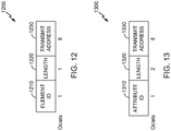
- FIG. 10 shows another exemplary information element 1000 that may be employed within the wireless communication system 100 of FIG. 1 .
- any device described herein, or another compatible device may transmit the information element 1000 such as, for example, the AP 124 ( FIG. 1 ), a STA 126a-106d ( FIG. 1 ), and/or the wireless device 202 ( FIG. 2 ).
- One or more messages in the wireless communication system 100 may include the information element 1000 such as, for example, the beacon 400 ( FIG. 4 ), the beacon 500 ( FIG. 5 ), the discovery frame 600 ( FIG. 6 ), and/or a probe response.
- the information element 1000 may include and/or replace the discovery period field 522 and/or the DW information field 529, discussed above with respect to FIG. 5 .
- the information element 1000 includes an element identification (ID) field 1010, a length field 1020, a timing synchronization (TSF) of next discovery period (DP) field 1030, a discovery window (DW) duration field 1040, and a discovery period (DP) field 1050, and a transmit address 1060.
- ID element identification
- TDF timing synchronization
- DP next discovery period
- DW discovery window
- DP discovery period
- the element identifier field 1010 shown is one octet long. In some implementations, the element identifier field 1010 may be two, five, or twelve octets long. In some implementations, the element identifier field 1010 may be of variable length, such as varying length from signal to signal and/or as between service providers. The element identifier field 1010 may include a value which identifies the element as a discovery information element 1000.
- the length field 1020 may be used to indicate the length of the information element 1000 or the total length of subsequent fields.
- the length field 1020 shown in FIG. 10 is one octet long. In some implementations, the length field 1020 may be two, five, or twelve octets long. In some implementations, the length field 1020 may be of variable length, such as varying length from signal to signal and/or as between service providers.
- the TSF of next DP field 1030 may indicate a start time of the next DP (for example, the start of the next discovery period 310 described above with respect to FIG. 3 ).
- the start time may be indicated via a timestamp in the format of the timestamp 420 ( FIG. 4 ) and/or 520 ( FIG. 5 ).
- the start time may be indicated using an absolute timestamp or a relative timestamp.
- the TSF of next DP field 1030 may indicate the start time of the next DP in ms, ⁇ s, time units (TUs), or another unit. In some embodiments, time units may be 1024 ⁇ s.
- the TSF of next DP field 1030 shown is eight octets long. In some implementations, TSF of next DP field 1030 may be two, five, or twelve octets long.
- the TSF of the current DP may be indicated instead of, or in addition to, the TSF of the next discovery period.
- one or more least significant bits of the TSF of the current and/or next DP may be indicated.
- the two least significant bytes may be indicated.
- the three, four, five, six, and seven least significant bytes may be indicated.
- the DW duration field 1040 may indicate a duration of the DW (for example, the duration of the DI 302 described above with respect to FIG. 3 ). In various embodiments, the DW duration field 1040 may indicate the a duration of the DW in ms, ⁇ s, time units (TUs), or another unit. In some embodiments, time units may be 1024 ⁇ s.
- the DW duration field 1040 shown is two octets long. In some implementations, DW duration field 1040 may be four, six, or eight octets long.
- the discovery period field 1050 may have the same format as the discovery period field 522 and/or the beacon interval field 422 described above with respect to FIGS. 5 and 4 , respectively.
- the discovery period field 1050 may indicate a length of the discovery period 310 (described above with respect to FIG. 3 ).
- the discovery period field 1050 may indicate the length of the DP 310 in ms, ⁇ s, time units (TUs), or another unit.
- time units may be 1024 ⁇ s.
- the discovery period field 1050 shown is between two and eight octets long. In some implementations, discovery period field 1050 may be two, four, six, or eight octets long.
- the discovery period field 1050 may be used when another discovery period field is too short to indicate the length of the DP.
- the discovery period field 522 is shown as two bytes long. If the DP comprises a length that may not be represented in two bytes, the discovery period field 522 may be set to a predetermined value (such as zero) indicating that the DP is indicated in another field.
- the wireless device 202 ( FIG. 2 ) receiving the beacon 500 may be configured to use the discovery period field 1050 when the discovery period field 522 is zero.
- the transmit address field 1060 may indicate an address (such as a MAC address) of a device transmitting the IE 1000.
- the transmit address field 1060 may have the same format as the SA field 412 ( FIG. 4 ), 512 ( FIG. 5 ), and/or 612 ( FIG. 6 ).
- the transmit address field 1060 shown is six octets long. In some implementations, transmit address field 1060 may be four, five, or eight octets long.
- the AP 104 may indicate the TSF of the next DP, the DW duration, the DP, and/or the transmit address in an attribute of an information element, in addition to, or instead of the IE 1000.
- the attribute may be in a vendor-specific IE.
- FIG. 11 shows an exemplary discovery window attribute 1100 that may be employed within the wireless communication system 100 of FIG. 1 .
- any device described herein, or another compatible device may transmit the DW attribute 1100 such as, for example, the AP 134 ( FIG. 1 ), a STA 136a-106d ( FIG. 1 ), and/or the wireless device 202 ( FIG. 2 ).
- One or more messages in the wireless communication system 100 may include the DW attribute 1100 such as, for example, the beacon 400 ( FIG. 4 ), the beacon 500 ( FIG. 5 ), the discovery frame 600 ( FIG. 6 ), and/or a probe response.
- the DW attribute 1100 may include and/or replace the DW attribute 940 described above with respect to FIG 11 .
- the DW attribute 1100 includes an attribute ID 1110, a length field 1120, a TSF of next DP field 1130, a DW duration field 1140, a DP field 1150, and a transmit address 1160.
- the DW attribute 1100 may include additional fields, and fields may be rearranged, removed, and/or resized.
- the attribute identifier field 1110 shown is one octet long. In some implementations, the attribute identifier field 1110 may be two, five, or twelve octets long. In some implementations, the attribute identifier field 1110 may be of variable length, such as varying length from signal to signal and/or as between service providers. The attribute identifier field 1110 may include a value which identifies the element as a discovery window attribute 1140.
- the length field 1120 may be used to indicate the length of the discovery window attribute 1140 or the total length of subsequent fields.
- the length field 1120 shown in FIG. 11 is two octets long. In some implementations, the length field 1120 may be one, five, or twelve octets long. In some implementations, the length field 1120 may be of variable length, such as varying length from signal to signal and/or as between service providers.
- the TSF of next DP field 1130 may indicate a start time of the next DP (for example, the start of the next discovery period 310 described above with respect to FIG. 3 ).
- the start time may be indicated via a timestamp in the format of the timestamp 420 ( FIG. 4 ) and/or 520 ( FIG. 5 ).
- the start time may be indicated using an absolute timestamp or a relative timestamp.
- the TSF of next DP field 1130 may indicate the start time of the next DP in ms, ⁇ s, time units (TUs), or another unit. In some embodiments, time units may be 1024 ⁇ s.
- the TSF of next DP field 1130 shown is eight octets long. In some implementations, TSF of next DP field 1130 may be two, five, or twelve octets long.
- the TSF of the current DP may be indicated instead of, or in addition to, the TSF of the next discovery period.
- one or more least significant bits of the TSF of the current and/or next DP may be indicated.
- the two least significant bytes may be indicated.
- the three, four, five, six, and seven least significant bytes may be indicated.
- the DW duration field 1140 may indicate a duration of the DW (for example, the duration of the DI 302 described above with respect to FIG. 3 ). In various embodiments, the DW duration field 1140 may indicate the a duration of the DW in ms, ⁇ s, time units (TUs), or another unit. In some embodiments, time units may be 1024 ⁇ s.
- the DW duration field 1140 shown is two octets long. In some implementations, DW duration field 1140 may be four, six, or eight octets long.
- the discovery period field 1150 may have the same format as the discovery period field 522 and/or the beacon interval field 422 described above with respect to FIGS. 5 and 4 , respectively.
- the discovery period field 1150 may indicate a length of the discovery period 310 (described above with respect to FIG. 3 ).
- the discovery period field 1150 may indicate the length of the DP 310 in ms, ⁇ s, time units (TUs), or another unit. In some embodiments, time units may be 1024 ⁇ s.
- the discovery period field 1150 shown is between two and eight octets long. In some implementations, discovery period field 1150 may be two, four, six, or eight octets long.
- the discovery period field 1150 may be used when another discovery period field is too short to indicate the length of the DP.
- the discovery period field 522 is shown as two bytes long. If the DP comprises a length that may not be represented in two bytes, the discovery period field 522 may be set to a predetermined value (such as zero) indicating that the DP is indicated in another field.
- the wireless device 202 ( FIG. 2 ) receiving the beacon 500 may be configured to use the discovery period field 1150 when the discovery period field 522 is zero.
- the transmit address field 1160 may indicate an address (such as a MAC address) of a device transmitting the IE 1200.
- the transmit address field 1160 may have the same format as the SA field 412 ( FIG. 4 ), 512 ( FIG. 5 ), and/or 612 ( FIG. 6 ).
- the transmit address field 1160 shown is six octets long. In some implementations, transmit address field 1160 may be four, five, or eight octets long.
- the AP 104 may indicate the transmit address in an information element that does not include the TSF of the next DP, the DW duration, and/or the DP.
- FIG. 12 shows another exemplary information element 1200 that may be employed within the wireless communication system 100 of FIG. 1 .
- any device described herein, or another compatible device may transmit the information element 1200 such as, for example, the AP 144 ( FIG. 1 ), a STA 146a-106d ( FIG. 1 ), and/or the wireless device 202 ( FIG. 2 ).
- One or more messages in the wireless communication system 100 may include the information element 1200 such as, for example, the beacon 400 ( FIG. 4 ), the beacon 500 ( FIG. 5 ), the discovery frame 600 ( FIG. 6 ), and/or a probe response.
- the information element 1200 includes an element identification (ID) field 1210, a length field 1220, and a transmit address 1230.
- ID element identification
- the information element 1200 may include additional fields, and fields may be rearranged, removed, and/or resized.
- the element identifier field 1210 shown is one octet long. In some implementations, the element identifier field 1210 may be two, five, or twelve octets long. In some implementations, the element identifier field 1210 may be of variable length, such as varying length from signal to signal and/or as between service providers. The element identifier field 1210 may include a value which identifies the element as a discovery information element 1200.
- the length field 1220 may be used to indicate the length of the information element 1200 or the total length of subsequent fields.
- the length field 1220 shown in FIG. 12 is one octet long. In some implementations, the length field 1220 may be two, five, or twelve octets long. In some implementations, the length field 1220 may be of variable length, such as varying length from signal to signal and/or as between service providers.
- the transmit address field 1230 may indicate an address (such as a MAC address) of a device transmitting the IE 1200.
- the transmit address field 1230 may have the same format as the SA field 412 ( FIG. 4 ), 512 ( FIG. 5 ), and/or 612 ( FIG. 6 ).
- the transmit address field 1230 shown is six octets long. In some implementations, transmit address field 1230 may be four, five, or eight octets long.
- the AP 104 may indicate the transmit address in an attribute of an information element that does not include the TSF of the next DP, the DW duration, and/or the DP.
- FIG. 13 shows an exemplary transmit address attribute 1300 that may be employed within the wireless communication system 100 of FIG. 1 .
- any device described herein, or another compatible device may transmit the DW attribute 1300 such as, for example, the AP 154 ( FIG. 1 ), a STA 156a-106d ( FIG. 1 ), and/or the wireless device 202 ( FIG. 2 ).
- One or more messages in the wireless communication system 100 may include the DW attribute 1300 such as, for example, the beacon 400 ( FIG. 4 ), the beacon 500 ( FIG. 5 ), the discovery frame 600 ( FIG. 6 ), and/or a probe response.
- the DW attribute 1300 includes an attribute ID 1310, a length field 1320, and a transmit address 1330.
- the DW attribute 1300 may include additional fields, and fields may be rearranged, removed, and/or resized.
- the attribute identifier field 1310 shown is one octet long. In some implementations, the attribute identifier field 1310 may be two, five, or twelve octets long. In some implementations, the attribute identifier field 1310 may be of variable length, such as varying length from signal to signal and/or as between service providers. The attribute identifier field 1310 may include a value which identifies the element as a transmit address attribute 1540.
- the length field 1320 may be used to indicate the length of the transmit address attribute 1540 or the total length of subsequent fields.
- the length field 1320 shown in FIG. 13 is two octets long. In some implementations, the length field 1320 may be one, five, or twelve octets long. In some implementations, the length field 1320 may be of variable length, such as varying length from signal to signal and/or as between service providers.
- the transmit address field 1330 may indicate an address (such as a MAC address) of a device transmitting the IE 1200.
- the transmit address field 1330 may have the same format as the SA field 412 ( FIG. 4 ), 512 ( FIG. 5 ), and/or 612 ( FIG. 6 ).
- the transmit address field 1330 shown is six octets long. In some implementations, transmit address field 1330 may be four, five, or eight octets long.
- a sync frame may include a discovery window information element indicating a start time of a discovery window and a discovery period indicator.
- a sync frame having a beacon type may be referred to as a beacon.
- any reference to an element herein using a designation such as "first,” “second,” and so forth does not generally limit the quantity or order of those elements. Rather, these designations may be used herein as a convenient method of distinguishing between two or more elements or instances of an element. Thus, a reference to first and second elements does not mean that only two elements may be employed there or that the first element may precede the second element in some manner. Also, unless stated otherwise a set of elements may include one or more elements.
- Information and signals may be represented using any of a variety of different technologies and techniques.
- data, instructions, commands, information, signals, bits, symbols, and chips that may be referenced throughout the above description may be represented by voltages, currents, electromagnetic waves, magnetic fields or particles, optical fields or particles, or any combination thereof.
- any of the various illustrative logical blocks, modules, processors, means, circuits, and algorithm steps described in connection with the aspects disclosed herein may be implemented as electronic hardware (e.g., a digital implementation, an analog implementation, or a combination of the two, which may be designed using source coding or some other technique), various forms of program or design code incorporating instructions (which may be referred to herein, for convenience, as "software” or a "software module), or combinations of both.
- software or a “software module”
- various illustrative components, blocks, modules, circuits, and steps have been described above generally in terms of their functionality. Whether such functionality is implemented as hardware or software depends upon the particular application and design constraints imposed on the overall system. Skilled artisans may implement the described functionality in varying ways for each particular application, but such implementation decisions may not be interpreted as causing a departure from the scope of the present disclosure.
- the various illustrative logical blocks, modules, and circuits described in connection with the aspects disclosed herein and in connection with FIGS. 1-13 may be implemented within or performed by an integrated circuit (IC), an access terminal, or an access point.
- the IC may include a general purpose processor, a digital signal processor (DSP), an application specific integrated circuit (ASIC), a field programmable gate array (FPGA) or other programmable logic device, discrete gate or transistor logic, discrete hardware components, electrical components, optical components, mechanical components, or any combination thereof designed to perform the functions described herein, and may execute codes or instructions that reside within the IC, outside of the IC, or both.
- the logical blocks, modules, and circuits may include antennas and/or transceivers to communicate with various components within the network or within the device.
- a general purpose processor may be a microprocessor, but in the alternative, the processor may be any conventional processor, controller, microcontroller, or state machine.
- a processor may also be implemented as a combination of computing devices, e.g., a combination of a DSP and a microprocessor, a plurality of microprocessors, one or more microprocessors in conjunction with a DSP core, or any other such configuration.
- the functionality of the modules may be implemented in some other manner as taught herein.
- the functionality described herein (e.g., with regard to one or more of the accompanying figures) may correspond in some aspects to similarly designated "means for" functionality in the appended claims.
- Computer-readable media includes both computer storage media and communication media including any medium that may be enabled to transfer a computer program from one place to another.
- a storage media may be any available media that may be accessed by a computer.
- such computer-readable media may include RAM, ROM, EEPROM, CD-ROM or other optical disk storage, magnetic disk storage or other magnetic storage devices, or any other medium that may be used to store desired program code in the form of instructions or data structures and that may be accessed by a computer.
- Disk and disc includes compact disc (CD), laser disc, optical disc, digital versatile disc (DVD), floppy disk, and blu-ray disc where disks usually reproduce data magnetically, while discs reproduce data optically with lasers. Combinations of the above may also be included within the scope of computer-readable media. Additionally, the operations of a method or algorithm may reside as one or any combination or set of codes and instructions on a machine readable medium and computer-readable medium, which may be incorporated into a computer program product.
Applications Claiming Priority (7)
| Application Number | Priority Date | Filing Date | Title |
|---|---|---|---|
| US201361751712P | 2013-01-11 | 2013-01-11 | |
| US201361757451P | 2013-01-28 | 2013-01-28 | |
| US201361762249P | 2013-02-07 | 2013-02-07 | |
| US201361799651P | 2013-03-15 | 2013-03-15 | |
| US201361815190P | 2013-04-23 | 2013-04-23 | |
| US14/105,114 US9820131B2 (en) | 2013-01-11 | 2013-12-12 | Systems and methods for formatting frames in neighborhood aware networks |
| PCT/US2013/075854 WO2014109875A1 (en) | 2013-01-11 | 2013-12-17 | Systems and methods for formatting frames in neighborhood aware networks |
Publications (2)
| Publication Number | Publication Date |
|---|---|
| EP2944105A1 EP2944105A1 (en) | 2015-11-18 |
| EP2944105B1 true EP2944105B1 (en) | 2018-05-30 |
Family
ID=51165074
Family Applications (2)
| Application Number | Title | Priority Date | Filing Date |
|---|---|---|---|
| EP13821030.7A Active EP2944105B1 (en) | 2013-01-11 | 2013-12-17 | Systems and methods for formatting frames in neighborhood aware networks |
| EP13821268.3A Active EP2944106B1 (en) | 2013-01-11 | 2013-12-17 | Systems and methods for formatting frames in neighborhood aware networks |
Family Applications After (1)
| Application Number | Title | Priority Date | Filing Date |
|---|---|---|---|
| EP13821268.3A Active EP2944106B1 (en) | 2013-01-11 | 2013-12-17 | Systems and methods for formatting frames in neighborhood aware networks |
Country Status (9)
| Country | Link |
|---|---|
| US (2) | US9820131B2 (zh) |
| EP (2) | EP2944105B1 (zh) |
| JP (2) | JP6453236B2 (zh) |
| KR (2) | KR102144436B1 (zh) |
| CN (2) | CN104969587B (zh) |
| ES (2) | ES2685590T3 (zh) |
| HU (2) | HUE039627T2 (zh) |
| TW (2) | TWI508585B (zh) |
| WO (2) | WO2014109875A1 (zh) |
Families Citing this family (56)
| Publication number | Priority date | Publication date | Assignee | Title |
|---|---|---|---|---|
| GB2506367B (en) * | 2012-09-26 | 2015-01-07 | Imagination Tech Ltd | Method and system for wirelessly transmitting data |
| US10039073B2 (en) | 2013-01-03 | 2018-07-31 | Qualcomm Incorporated | Method for determining location of wireless devices |
| US9820131B2 (en) | 2013-01-11 | 2017-11-14 | Qualcomm Incorporated | Systems and methods for formatting frames in neighborhood aware networks |
| US9295015B2 (en) * | 2013-02-12 | 2016-03-22 | Intel IP Corporation | Methods, wireless communication stations, and system for synchronizing devices and neighbor area networking (NAN) configuration |
| US9154934B2 (en) * | 2013-03-28 | 2015-10-06 | Futurewei Technologies, Inc. | System and method for pre-association discovery |
| WO2014168640A1 (en) * | 2013-04-09 | 2014-10-16 | Intel IP Corporation | Systems, apparatus and methods using sync beacons in neighbor awareness networking (nan) |
| US20140328168A1 (en) | 2013-05-06 | 2014-11-06 | Minyoung Park | Apparatus, system and method of adjusting transmission intervals for discovery frames |
| US10298545B2 (en) | 2013-09-12 | 2019-05-21 | International Business Machines Corporation | Secure processing environment for protecting sensitive information |
| EP2897418B1 (en) * | 2014-01-20 | 2016-06-01 | Alcatel Lucent | Advertising storage capabilities accessible via a wireless local area network |
| WO2015126187A1 (ko) * | 2014-02-20 | 2015-08-27 | 엘지전자 주식회사 | 무선 통신 시스템에서 nan 단말의 멀티캐스트 주소 공유 방법 및 장치 |
| WO2015134741A1 (en) | 2014-03-05 | 2015-09-11 | Marvell World Trade Ltd. | Method and apparatus for estimating distance between network devices in a wireless network |
| US10182413B2 (en) | 2014-07-30 | 2019-01-15 | Qualcomm Incorporated | Wireless positioning using scheduled transmissions |
| JP6344475B2 (ja) * | 2014-08-19 | 2018-06-20 | 富士通株式会社 | 基地局装置、無線通信システム、および、通信方法 |
| US9894594B2 (en) * | 2014-08-29 | 2018-02-13 | Huawei Technologies Co., Ltd. | System and method for cumulative beacons |
| KR101972028B1 (ko) * | 2014-09-04 | 2019-04-24 | 엘지전자 주식회사 | Nan을 위한 무선 자원 스케줄링 방법 및 장치 |
| US9992661B2 (en) | 2014-09-24 | 2018-06-05 | Qualcomm Incorporated | Neighbor aware network logical channels |
| US9769645B2 (en) * | 2014-10-16 | 2017-09-19 | Qualcomm Incorporated | Communication between devices of a neighbor aware network |
| US9763221B2 (en) | 2014-10-16 | 2017-09-12 | Qualcomm Incorporated | Communication between devices of a neighbor aware network |
| US9961668B2 (en) * | 2014-10-16 | 2018-05-01 | Qualcomm Incorporated | Communication between devices of a neighbor aware network |
| US9763223B2 (en) * | 2014-10-16 | 2017-09-12 | Qualcomm Incorporated | Communication between devices of a neighbor aware network |
| US10863431B2 (en) * | 2014-11-06 | 2020-12-08 | Qualcomm Incorporated | Systems and methods for synchronization within a neighborhood aware network |
| KR102251326B1 (ko) * | 2014-11-25 | 2021-05-12 | 삼성전자주식회사 | 근접 네트워크 구성 방법 및 그 전자 장치 |
| KR102208438B1 (ko) * | 2014-11-26 | 2021-01-27 | 삼성전자주식회사 | 근접 서비스 데이터 송신 방법 및 그 전자 장치 |
| US10827484B2 (en) | 2014-12-12 | 2020-11-03 | Qualcomm Incorporated | Traffic advertisement in neighbor aware network (NAN) data path |
| US9949236B2 (en) * | 2014-12-12 | 2018-04-17 | Qualcomm Incorporated | Traffic advertisement in neighbor aware network (NAN) data path |
| US10820314B2 (en) | 2014-12-12 | 2020-10-27 | Qualcomm Incorporated | Traffic advertisement in neighbor aware network (NAN) data path |
| US20170346673A1 (en) * | 2014-12-15 | 2017-11-30 | Nokia Technologies Oy | Identifying wireless service |
| US20160174139A1 (en) * | 2014-12-16 | 2016-06-16 | Intel Corporation | Ranging profiling for neighbor awareness networking |
| US20160183113A1 (en) * | 2014-12-23 | 2016-06-23 | Qualcomm Incorporated | Efficient pairwise ranging to nodes in a large cluster |
| US10051664B2 (en) * | 2015-01-01 | 2018-08-14 | Intel IP Corporation | Apparatus, system and method of communicating during a discovery window |
| WO2016126137A1 (ko) * | 2015-02-05 | 2016-08-11 | 엘지전자 주식회사 | 무선 통신 시스템에서 nan 단말의 신호 송수신 방법 및 장치 |
| WO2016129915A1 (ko) * | 2015-02-10 | 2016-08-18 | 엘지전자 주식회사 | 무선 통신 시스템에서 데이터 전송 방법 및 이를 이용한 장치 |
| US9949156B2 (en) | 2015-02-13 | 2018-04-17 | Qualcomm Incorporated | Efficient ranging |
| US10455401B2 (en) | 2015-02-24 | 2019-10-22 | Apple Inc. | Neighbor awareness networking datapath—reciprocation and coexistence |
| WO2016149890A1 (zh) * | 2015-03-20 | 2016-09-29 | 华为技术有限公司 | 一种nan设备之间的距离测量方法及nan设备 |
| US20160285630A1 (en) * | 2015-03-23 | 2016-09-29 | Qualcomm Incorporated | Private service identifiers in neighborhood aware networks |
| US20160286398A1 (en) * | 2015-03-23 | 2016-09-29 | Qualcomm Incorporated | Schedule selection and connection setup between devices participating in a nan data link |
| US20180054798A1 (en) * | 2015-04-20 | 2018-02-22 | Intel IP Corporation | Apparatus, system and method of communicating in a data group |
| US10123200B2 (en) * | 2015-04-20 | 2018-11-06 | Apple Inc. | Neighbor awareness networking—channel sequence |
| US10051566B2 (en) | 2015-04-30 | 2018-08-14 | Futurewei Technologies, Inc. | System and method for data communication in a decentralized and power efficient manner |
| US10165046B2 (en) | 2015-05-22 | 2018-12-25 | Futurewei Technologies, Inc. | Method and system for transmitting data among peer stations in a decentralized manner with high channel efficiency |
| WO2016195212A1 (ko) * | 2015-05-29 | 2016-12-08 | 엘지전자 주식회사 | 무선 통신 시스템에서 nan 단말의 상태 천이 방법 및 장치 |
| US10334422B2 (en) * | 2015-06-15 | 2019-06-25 | Qualcomm Incorporated | Methods and apparatus for wireless discovery location and ranging within a neighborhood aware network |
| WO2017018812A1 (ko) * | 2015-07-29 | 2017-02-02 | 엘지전자 주식회사 | 무선 통신 시스템에서 레인징 오퍼레이션을 수행하는 방법 및 장치 |
| JP6643848B2 (ja) * | 2015-09-24 | 2020-02-12 | キヤノン株式会社 | 通信装置、通信方法、およびプログラム |
| WO2017065561A1 (ko) * | 2015-10-14 | 2017-04-20 | 엘지전자 주식회사 | 무선 통신 시스템에서 nan 단말이 프레임을 전송하는 방법 및 장치 |
| US9842132B2 (en) | 2015-10-23 | 2017-12-12 | International Business Machines Corporation | Bloom filter index for device discovery |
| US10397767B2 (en) * | 2015-11-02 | 2019-08-27 | Apple Inc. | NAN further availability schedule indications |
| US9743267B2 (en) | 2015-12-16 | 2017-08-22 | Motorola Solutions, Inc. | Method, device, and system for improving device pairing between a scanning wireless radio communication device and target wireless electronic devices |
| US10098135B2 (en) * | 2016-02-22 | 2018-10-09 | Intel IP Corporation | Action frame for schedule update in a NAN |
| JP7133898B2 (ja) * | 2016-07-21 | 2022-09-09 | キヤノン株式会社 | 通信装置、通信装置の制御方法、およびプログラム |
| US9907047B1 (en) * | 2016-08-30 | 2018-02-27 | Qualcomm Incorporated | Passive positioning procedure and use of single burst ASAP FTM sessions |
| US10042875B2 (en) | 2016-09-26 | 2018-08-07 | International Business Machines Corporation | Bloom filter index for device discovery |
| WO2018190928A1 (en) * | 2017-04-14 | 2018-10-18 | Ehud Reshef | Modified header for communication in a next-generation wi-fi network |
| CN114423072A (zh) * | 2017-12-22 | 2022-04-29 | 华为技术有限公司 | 用于无线通信的装置和方法 |
| EP3911024A4 (en) * | 2019-01-08 | 2022-06-15 | Sony Group Corporation | COMMUNICATION DEVICE AND COMMUNICATION METHOD |
Citations (1)
| Publication number | Priority date | Publication date | Assignee | Title |
|---|---|---|---|---|
| US20110153773A1 (en) * | 2009-12-23 | 2011-06-23 | Apple Inc. | Efficient service advertisement and discovery in a peer-to-peer networking environment with cooperative advertisement |
Family Cites Families (50)
| Publication number | Priority date | Publication date | Assignee | Title |
|---|---|---|---|---|
| DE69930918T2 (de) | 1999-01-25 | 2006-11-30 | International Business Machines Corp. | Dienstankündigungen in drahtlosen lokalen Netzen |
| US7257095B2 (en) | 2003-07-30 | 2007-08-14 | Texas Instruments Incorporated | Power saving via physical layer address filtering in WLANs |
| JP4396416B2 (ja) * | 2003-10-24 | 2010-01-13 | ソニー株式会社 | 無線通信システム、無線通信装置及び無線通信方法、並びにコンピュータ・プログラム |
| JP2005151213A (ja) | 2003-11-17 | 2005-06-09 | Matsushita Electric Ind Co Ltd | 無線通信方式 |
| CN100461728C (zh) | 2005-01-04 | 2009-02-11 | 华为技术有限公司 | 无线通信方法 |
| TWI328363B (en) * | 2005-03-24 | 2010-08-01 | Lg Electronics Inc | Method of connecting to network in broadband wireless access system |
| US7778335B2 (en) | 2005-04-22 | 2010-08-17 | Xm Satellite Radio, Inc. | Method and system for hierarchical modulation and demodulation for digital radio |
| WO2006115367A1 (en) * | 2005-04-25 | 2006-11-02 | Samsung Electronics Co., Ltd. | System and method for providing broadcast service in a mobile communication system |
| US20060285528A1 (en) * | 2005-06-21 | 2006-12-21 | Xia Gao | Method and apparatus for power saving in beacon generation of wireless networks in ad hoc mode |
| US7553540B2 (en) * | 2005-12-30 | 2009-06-30 | E. I. Du Pont De Nemours And Company | Fluoropolymer coated films useful for photovoltaic modules |
| US7613156B2 (en) | 2006-06-08 | 2009-11-03 | Motorola, Inc. | Method for energy efficient prospective peer discovery in an ad hoc network |
| JP2008001458A (ja) | 2006-06-21 | 2008-01-10 | Canon Inc | シート給送装置及び画像形成装置 |
| EP3554171B1 (en) * | 2006-07-07 | 2021-09-01 | Samsung Electronics Co., Ltd. | Apparatus and method for reducing volume of resource allocation information message in a broadband wireless communication system |
| ZA200900132B (en) | 2006-08-04 | 2010-03-31 | Microsoft Corp | Synchronization between wireless devices while saving power |
| US20080031208A1 (en) * | 2006-08-04 | 2008-02-07 | Microsoft Corporation | Synchronization between wireless devices while saving power |
| US7860038B2 (en) | 2006-08-04 | 2010-12-28 | Microsoft Corporation | Wireless support for portable media player devices |
| GB0615871D0 (en) | 2006-08-10 | 2006-09-20 | Intersurgical Ag | Improvements relating to humidification chambers |
| US7738846B2 (en) * | 2006-08-17 | 2010-06-15 | Nokia Corporation | Shared scanning in distributed networks |
| KR20080037247A (ko) * | 2006-10-25 | 2008-04-30 | 삼성전자주식회사 | 광대역 무선통신 시스템에서 레인징 에러 상황 대처 방법 |
| KR101404674B1 (ko) * | 2007-06-15 | 2014-06-09 | 삼성전자주식회사 | 무선통신 시스템에서 유휴 모드 운영 방법 및 장치 |
| US8189577B2 (en) | 2007-06-15 | 2012-05-29 | Silver Spring Networks, Inc. | Network utilities in wireless mesh communications networks |
| US8072951B2 (en) | 2007-06-15 | 2011-12-06 | Silver Spring Networks, Inc. | Method and system for providing routing protocols in a frequency hopping spread spectrum network |
| US7881340B2 (en) | 2007-10-22 | 2011-02-01 | The Johns Hopkins University | Decentralized media access control for ad-hoc mobile wireless network |
| KR100955470B1 (ko) * | 2008-01-09 | 2010-04-30 | 대한민국(관리부서 질병관리본부장) | 탄저 방어 항원의 제조 방법 |
| US20090327292A1 (en) | 2008-06-27 | 2009-12-31 | Motorola, Inc. | Ensuring consistency among shared copies of a data element |
| WO2010035157A1 (en) | 2008-09-25 | 2010-04-01 | Koninklijke Philips Electronics N.V. | Directional discovery protocol with coordinated channel selection |
| US8203984B2 (en) * | 2008-12-19 | 2012-06-19 | Intel Corporation | Power management for wireless networks |
| US20100172275A1 (en) | 2009-01-07 | 2010-07-08 | Microsoft Corporation | Energy Efficient Device Discovery with Short-Range Radios |
| US8054771B2 (en) | 2009-02-20 | 2011-11-08 | Motorola Mobility, Inc. | Method and system for adding a new connection identifier to an existing power save class |
| US9007968B2 (en) * | 2009-06-16 | 2015-04-14 | Samsung Electronics Co., Ltd. | System and method for wireless multi-band networks association and maintenance |
| US8649266B2 (en) * | 2009-07-27 | 2014-02-11 | Lester F. Ludwig | Flow state aware management of QoS with a distributed classifier |
| US9900759B2 (en) | 2009-11-04 | 2018-02-20 | Qualcomm Incorporated | Method and apparatus for peer discovery in a wireless communication network |
| EP2487963B1 (en) | 2009-11-17 | 2019-08-21 | Samsung Electronics Co., Ltd. | Method and device for investigating wifi display service in a wifi direct network |
| US8437275B2 (en) * | 2009-12-11 | 2013-05-07 | Microsoft Corporation | Remote wireless service invocation with efficient power use on target wireless device |
| US8559340B2 (en) * | 2009-12-22 | 2013-10-15 | Samsung Electronics Co., Ltd. | Method and apparatus for service discovery in Wi-Fi direct network |
| US8565169B2 (en) | 2010-01-12 | 2013-10-22 | Qualcomm Incorporated | Timing synchronization methods and apparatus |
| WO2011159093A2 (en) | 2010-06-14 | 2011-12-22 | Samsung Electronics Co., Ltd. | Hybrid delivery mechanism in a multimedia transmission system |
| US8520648B2 (en) | 2010-06-14 | 2013-08-27 | Intel Corporation | Beacon transmission techniques in directional wireless networks |
| US20110310791A1 (en) | 2010-06-22 | 2011-12-22 | Qualcomm Incorporated | Automatic neighbor relation (anr) functions for relay nodes, home base stations, and related entities |
| WO2012060611A2 (ko) | 2010-11-03 | 2012-05-10 | 엘지전자 주식회사 | 장치 탐색 방법 및 그를 이용한 통신 장치 |
| TWI501601B (zh) | 2011-08-15 | 2015-09-21 | Mediatek Inc | 裝置搜尋的處理方法 |
| US10271293B2 (en) | 2011-11-18 | 2019-04-23 | Apple Inc. | Group formation within a synchronized hierarchy of peer-to-peer devices |
| US20130132500A1 (en) | 2011-11-18 | 2013-05-23 | Apple Inc. | Selection of a master in a peer-to-peer network environment |
| US9008062B2 (en) * | 2012-01-09 | 2015-04-14 | Futurewei Technologies, Inc. | Systems and methods for AP discovery with FILS beacon |
| KR20130091098A (ko) | 2012-02-07 | 2013-08-16 | 한국전자통신연구원 | 노드 탐색 메시지를 전송하기 위한 장치 및 방법 |
| US9661558B2 (en) * | 2012-06-01 | 2017-05-23 | Apple Inc. | Service constraint advertisement and discovery |
| US9554324B2 (en) | 2012-10-16 | 2017-01-24 | Stmicroelectronics, Inc. | Fast initial link setup (FILS) frame content for a wireless network |
| US11496948B2 (en) | 2012-10-19 | 2022-11-08 | Samsung Electronics Co., Ltd. | System and method for ad-hoc/network assisted device discovery protocol for device to device communications |
| US9042828B2 (en) * | 2012-11-26 | 2015-05-26 | Nokia Corporation | Method, apparatus, and computer program product for optimized discovery between mobile devices |
| US9820131B2 (en) | 2013-01-11 | 2017-11-14 | Qualcomm Incorporated | Systems and methods for formatting frames in neighborhood aware networks |
-
2013
- 2013-12-12 US US14/105,114 patent/US9820131B2/en active Active
- 2013-12-12 US US14/105,088 patent/US10477376B2/en active Active
- 2013-12-17 CN CN201380070037.5A patent/CN104969587B/zh active Active
- 2013-12-17 WO PCT/US2013/075854 patent/WO2014109875A1/en active Application Filing
- 2013-12-17 KR KR1020157021247A patent/KR102144436B1/ko active IP Right Grant
- 2013-12-17 EP EP13821030.7A patent/EP2944105B1/en active Active
- 2013-12-17 ES ES13821268.3T patent/ES2685590T3/es active Active
- 2013-12-17 CN CN201380070038.XA patent/CN104919828B/zh active Active
- 2013-12-17 EP EP13821268.3A patent/EP2944106B1/en active Active
- 2013-12-17 HU HUE13821030A patent/HUE039627T2/hu unknown
- 2013-12-17 JP JP2015552646A patent/JP6453236B2/ja active Active
- 2013-12-17 WO PCT/US2013/075844 patent/WO2014109874A1/en active Application Filing
- 2013-12-17 JP JP2015552645A patent/JP6400599B2/ja active Active
- 2013-12-17 HU HUE13821268A patent/HUE039066T2/hu unknown
- 2013-12-17 ES ES13821030.7T patent/ES2683708T3/es active Active
- 2013-12-17 KR KR1020157021345A patent/KR101862113B1/ko active IP Right Grant
- 2013-12-30 TW TW102149087A patent/TWI508585B/zh active
-
2014
- 2014-01-08 TW TW103100684A patent/TWI575994B/zh not_active IP Right Cessation
Patent Citations (1)
| Publication number | Priority date | Publication date | Assignee | Title |
|---|---|---|---|---|
| US20110153773A1 (en) * | 2009-12-23 | 2011-06-23 | Apple Inc. | Efficient service advertisement and discovery in a peer-to-peer networking environment with cooperative advertisement |
Non-Patent Citations (1)
| Title |
|---|
| "Wi-Fi Peer-to-Peer (P2P) Technical Specification v1.2", vol. V1.2, 14 December 2011 (2011-12-14), pages 1 - 159, XP008165048, Retrieved from the Internet <URL:https://www.wi-fi.org/knowledge-center/published-specifications> * |
Also Published As
| Publication number | Publication date |
|---|---|
| CN104919828A (zh) | 2015-09-16 |
| US20140198725A1 (en) | 2014-07-17 |
| HUE039066T2 (hu) | 2018-12-28 |
| CN104969587A (zh) | 2015-10-07 |
| TWI575994B (zh) | 2017-03-21 |
| US20140198724A1 (en) | 2014-07-17 |
| HUE039627T2 (hu) | 2019-01-28 |
| EP2944106A1 (en) | 2015-11-18 |
| JP2016507180A (ja) | 2016-03-07 |
| EP2944105A1 (en) | 2015-11-18 |
| CN104919828B (zh) | 2018-11-27 |
| TWI508585B (zh) | 2015-11-11 |
| KR102144436B1 (ko) | 2020-08-13 |
| ES2685590T3 (es) | 2018-10-10 |
| WO2014109874A1 (en) | 2014-07-17 |
| JP6453236B2 (ja) | 2019-01-16 |
| ES2683708T3 (es) | 2018-09-27 |
| JP6400599B2 (ja) | 2018-10-03 |
| TW201436631A (zh) | 2014-09-16 |
| KR20150107782A (ko) | 2015-09-23 |
| TW201429285A (zh) | 2014-07-16 |
| CN104969587B (zh) | 2019-02-15 |
| US9820131B2 (en) | 2017-11-14 |
| KR101862113B1 (ko) | 2018-05-29 |
| WO2014109875A1 (en) | 2014-07-17 |
| KR20150107786A (ko) | 2015-09-23 |
| US10477376B2 (en) | 2019-11-12 |
| JP2016507179A (ja) | 2016-03-07 |
| EP2944106B1 (en) | 2018-06-06 |
Similar Documents
| Publication | Publication Date | Title |
|---|---|---|
| EP2944105B1 (en) | Systems and methods for formatting frames in neighborhood aware networks | |
| AU2014225958B2 (en) | Systems and methods for discovering devices in a neighborhood aware network | |
| US9800389B2 (en) | Systems and methods for discovering and synchronizing within a neighbor aware network | |
| US9872227B2 (en) | Systems and methods for identification in a neighborhood aware network | |
| JP2016507180A5 (zh) |
Legal Events
| Date | Code | Title | Description |
|---|---|---|---|
| PUAI | Public reference made under article 153(3) epc to a published international application that has entered the european phase |
Free format text: ORIGINAL CODE: 0009012 |
|
| 17P | Request for examination filed |
Effective date: 20150617 |
|
| AK | Designated contracting states |
Kind code of ref document: A1 Designated state(s): AL AT BE BG CH CY CZ DE DK EE ES FI FR GB GR HR HU IE IS IT LI LT LU LV MC MK MT NL NO PL PT RO RS SE SI SK SM TR |
|
| AX | Request for extension of the european patent |
Extension state: BA ME |
|
| DAX | Request for extension of the european patent (deleted) | ||
| 17Q | First examination report despatched |
Effective date: 20170629 |
|
| GRAP | Despatch of communication of intention to grant a patent |
Free format text: ORIGINAL CODE: EPIDOSNIGR1 |
|
| RIC1 | Information provided on ipc code assigned before grant |
Ipc: H04W 76/02 20090101ALI20171115BHEP Ipc: H04W 84/18 20090101ALN20171115BHEP Ipc: H04W 4/00 20090101ALN20171115BHEP Ipc: H04W 8/00 20090101AFI20171115BHEP |
|
| INTG | Intention to grant announced |
Effective date: 20171213 |
|
| GRAS | Grant fee paid |
Free format text: ORIGINAL CODE: EPIDOSNIGR3 |
|
| GRAA | (expected) grant |
Free format text: ORIGINAL CODE: 0009210 |
|
| AK | Designated contracting states |
Kind code of ref document: B1 Designated state(s): AL AT BE BG CH CY CZ DE DK EE ES FI FR GB GR HR HU IE IS IT LI LT LU LV MC MK MT NL NO PL PT RO RS SE SI SK SM TR |
|
| REG | Reference to a national code |
Ref country code: GB Ref legal event code: FG4D |
|
| REG | Reference to a national code |
Ref country code: CH Ref legal event code: EP |
|
| REG | Reference to a national code |
Ref country code: AT Ref legal event code: REF Ref document number: 1004882 Country of ref document: AT Kind code of ref document: T Effective date: 20180615 |
|
| REG | Reference to a national code |
Ref country code: IE Ref legal event code: FG4D |
|
| REG | Reference to a national code |
Ref country code: DE Ref legal event code: R096 Ref document number: 602013038317 Country of ref document: DE |
|
| REG | Reference to a national code |
Ref country code: NL Ref legal event code: FP |
|
| REG | Reference to a national code |
Ref country code: ES Ref legal event code: FG2A Ref document number: 2683708 Country of ref document: ES Kind code of ref document: T3 Effective date: 20180927 |
|
| REG | Reference to a national code |
Ref country code: LT Ref legal event code: MG4D |
|
| PG25 | Lapsed in a contracting state [announced via postgrant information from national office to epo] |
Ref country code: SE Free format text: LAPSE BECAUSE OF FAILURE TO SUBMIT A TRANSLATION OF THE DESCRIPTION OR TO PAY THE FEE WITHIN THE PRESCRIBED TIME-LIMIT Effective date: 20180530 Ref country code: NO Free format text: LAPSE BECAUSE OF FAILURE TO SUBMIT A TRANSLATION OF THE DESCRIPTION OR TO PAY THE FEE WITHIN THE PRESCRIBED TIME-LIMIT Effective date: 20180830 Ref country code: BG Free format text: LAPSE BECAUSE OF FAILURE TO SUBMIT A TRANSLATION OF THE DESCRIPTION OR TO PAY THE FEE WITHIN THE PRESCRIBED TIME-LIMIT Effective date: 20180830 Ref country code: CY Free format text: LAPSE BECAUSE OF FAILURE TO SUBMIT A TRANSLATION OF THE DESCRIPTION OR TO PAY THE FEE WITHIN THE PRESCRIBED TIME-LIMIT Effective date: 20180530 Ref country code: LT Free format text: LAPSE BECAUSE OF FAILURE TO SUBMIT A TRANSLATION OF THE DESCRIPTION OR TO PAY THE FEE WITHIN THE PRESCRIBED TIME-LIMIT Effective date: 20180530 |
|
| PG25 | Lapsed in a contracting state [announced via postgrant information from national office to epo] |
Ref country code: LV Free format text: LAPSE BECAUSE OF FAILURE TO SUBMIT A TRANSLATION OF THE DESCRIPTION OR TO PAY THE FEE WITHIN THE PRESCRIBED TIME-LIMIT Effective date: 20180530 Ref country code: RS Free format text: LAPSE BECAUSE OF FAILURE TO SUBMIT A TRANSLATION OF THE DESCRIPTION OR TO PAY THE FEE WITHIN THE PRESCRIBED TIME-LIMIT Effective date: 20180530 Ref country code: HR Free format text: LAPSE BECAUSE OF FAILURE TO SUBMIT A TRANSLATION OF THE DESCRIPTION OR TO PAY THE FEE WITHIN THE PRESCRIBED TIME-LIMIT Effective date: 20180530 Ref country code: GR Free format text: LAPSE BECAUSE OF FAILURE TO SUBMIT A TRANSLATION OF THE DESCRIPTION OR TO PAY THE FEE WITHIN THE PRESCRIBED TIME-LIMIT Effective date: 20180831 |
|
| REG | Reference to a national code |
Ref country code: AT Ref legal event code: MK05 Ref document number: 1004882 Country of ref document: AT Kind code of ref document: T Effective date: 20180530 |
|
| REG | Reference to a national code |
Ref country code: HU Ref legal event code: AG4A Ref document number: E039627 Country of ref document: HU |
|
| PG25 | Lapsed in a contracting state [announced via postgrant information from national office to epo] |
Ref country code: CZ Free format text: LAPSE BECAUSE OF FAILURE TO SUBMIT A TRANSLATION OF THE DESCRIPTION OR TO PAY THE FEE WITHIN THE PRESCRIBED TIME-LIMIT Effective date: 20180530 Ref country code: RO Free format text: LAPSE BECAUSE OF FAILURE TO SUBMIT A TRANSLATION OF THE DESCRIPTION OR TO PAY THE FEE WITHIN THE PRESCRIBED TIME-LIMIT Effective date: 20180530 Ref country code: DK Free format text: LAPSE BECAUSE OF FAILURE TO SUBMIT A TRANSLATION OF THE DESCRIPTION OR TO PAY THE FEE WITHIN THE PRESCRIBED TIME-LIMIT Effective date: 20180530 Ref country code: AT Free format text: LAPSE BECAUSE OF FAILURE TO SUBMIT A TRANSLATION OF THE DESCRIPTION OR TO PAY THE FEE WITHIN THE PRESCRIBED TIME-LIMIT Effective date: 20180530 Ref country code: EE Free format text: LAPSE BECAUSE OF FAILURE TO SUBMIT A TRANSLATION OF THE DESCRIPTION OR TO PAY THE FEE WITHIN THE PRESCRIBED TIME-LIMIT Effective date: 20180530 Ref country code: SK Free format text: LAPSE BECAUSE OF FAILURE TO SUBMIT A TRANSLATION OF THE DESCRIPTION OR TO PAY THE FEE WITHIN THE PRESCRIBED TIME-LIMIT Effective date: 20180530 Ref country code: PL Free format text: LAPSE BECAUSE OF FAILURE TO SUBMIT A TRANSLATION OF THE DESCRIPTION OR TO PAY THE FEE WITHIN THE PRESCRIBED TIME-LIMIT Effective date: 20180530 |
|
| REG | Reference to a national code |
Ref country code: CH Ref legal event code: PK Free format text: BERICHTIGUNGEN |
|
| RIC2 | Information provided on ipc code assigned after grant |
Ipc: H04W 76/02 20090101ALI20171115BHEP Ipc: H04W 84/18 20090101ALN20171115BHEP Ipc: H04W 8/00 20090101AFI20171115BHEP Ipc: H04W 4/00 20180101ALN20171115BHEP |
|
| PG25 | Lapsed in a contracting state [announced via postgrant information from national office to epo] |
Ref country code: SM Free format text: LAPSE BECAUSE OF FAILURE TO SUBMIT A TRANSLATION OF THE DESCRIPTION OR TO PAY THE FEE WITHIN THE PRESCRIBED TIME-LIMIT Effective date: 20180530 |
|
| REG | Reference to a national code |
Ref country code: DE Ref legal event code: R097 Ref document number: 602013038317 Country of ref document: DE |
|
| PLBE | No opposition filed within time limit |
Free format text: ORIGINAL CODE: 0009261 |
|
| STAA | Information on the status of an ep patent application or granted ep patent |
Free format text: STATUS: NO OPPOSITION FILED WITHIN TIME LIMIT |
|
| 26N | No opposition filed |
Effective date: 20190301 |
|
| PG25 | Lapsed in a contracting state [announced via postgrant information from national office to epo] |
Ref country code: SI Free format text: LAPSE BECAUSE OF FAILURE TO SUBMIT A TRANSLATION OF THE DESCRIPTION OR TO PAY THE FEE WITHIN THE PRESCRIBED TIME-LIMIT Effective date: 20180530 |
|
| REG | Reference to a national code |
Ref country code: CH Ref legal event code: PL |
|
| PG25 | Lapsed in a contracting state [announced via postgrant information from national office to epo] |
Ref country code: MC Free format text: LAPSE BECAUSE OF FAILURE TO SUBMIT A TRANSLATION OF THE DESCRIPTION OR TO PAY THE FEE WITHIN THE PRESCRIBED TIME-LIMIT Effective date: 20180530 Ref country code: LU Free format text: LAPSE BECAUSE OF NON-PAYMENT OF DUE FEES Effective date: 20181217 |
|
| REG | Reference to a national code |
Ref country code: IE Ref legal event code: MM4A |
|
| REG | Reference to a national code |
Ref country code: BE Ref legal event code: MM Effective date: 20181231 |
|
| PG25 | Lapsed in a contracting state [announced via postgrant information from national office to epo] |
Ref country code: IE Free format text: LAPSE BECAUSE OF NON-PAYMENT OF DUE FEES Effective date: 20181217 |
|
| PG25 | Lapsed in a contracting state [announced via postgrant information from national office to epo] |
Ref country code: AL Free format text: LAPSE BECAUSE OF FAILURE TO SUBMIT A TRANSLATION OF THE DESCRIPTION OR TO PAY THE FEE WITHIN THE PRESCRIBED TIME-LIMIT Effective date: 20180530 Ref country code: BE Free format text: LAPSE BECAUSE OF NON-PAYMENT OF DUE FEES Effective date: 20181231 |
|
| PG25 | Lapsed in a contracting state [announced via postgrant information from national office to epo] |
Ref country code: LI Free format text: LAPSE BECAUSE OF NON-PAYMENT OF DUE FEES Effective date: 20181231 Ref country code: CH Free format text: LAPSE BECAUSE OF NON-PAYMENT OF DUE FEES Effective date: 20181231 |
|
| PG25 | Lapsed in a contracting state [announced via postgrant information from national office to epo] |
Ref country code: MT Free format text: LAPSE BECAUSE OF NON-PAYMENT OF DUE FEES Effective date: 20181217 |
|
| PG25 | Lapsed in a contracting state [announced via postgrant information from national office to epo] |
Ref country code: TR Free format text: LAPSE BECAUSE OF FAILURE TO SUBMIT A TRANSLATION OF THE DESCRIPTION OR TO PAY THE FEE WITHIN THE PRESCRIBED TIME-LIMIT Effective date: 20180530 |
|
| PG25 | Lapsed in a contracting state [announced via postgrant information from national office to epo] |
Ref country code: PT Free format text: LAPSE BECAUSE OF FAILURE TO SUBMIT A TRANSLATION OF THE DESCRIPTION OR TO PAY THE FEE WITHIN THE PRESCRIBED TIME-LIMIT Effective date: 20180530 |
|
| PG25 | Lapsed in a contracting state [announced via postgrant information from national office to epo] |
Ref country code: MK Free format text: LAPSE BECAUSE OF NON-PAYMENT OF DUE FEES Effective date: 20180530 |
|
| PG25 | Lapsed in a contracting state [announced via postgrant information from national office to epo] |
Ref country code: IS Free format text: LAPSE BECAUSE OF FAILURE TO SUBMIT A TRANSLATION OF THE DESCRIPTION OR TO PAY THE FEE WITHIN THE PRESCRIBED TIME-LIMIT Effective date: 20180930 |
|
| PGFP | Annual fee paid to national office [announced via postgrant information from national office to epo] |
Ref country code: NL Payment date: 20211115 Year of fee payment: 9 Ref country code: FI Payment date: 20211126 Year of fee payment: 9 |
|
| PGFP | Annual fee paid to national office [announced via postgrant information from national office to epo] |
Ref country code: HU Payment date: 20211127 Year of fee payment: 9 |
|
| PGFP | Annual fee paid to national office [announced via postgrant information from national office to epo] |
Ref country code: ES Payment date: 20230109 Year of fee payment: 10 |
|
| PGFP | Annual fee paid to national office [announced via postgrant information from national office to epo] |
Ref country code: IT Payment date: 20221220 Year of fee payment: 10 |
|
| REG | Reference to a national code |
Ref country code: NL Ref legal event code: MM Effective date: 20230101 |
|
| PG25 | Lapsed in a contracting state [announced via postgrant information from national office to epo] |
Ref country code: NL Free format text: LAPSE BECAUSE OF NON-PAYMENT OF DUE FEES Effective date: 20230101 |
|
| PG25 | Lapsed in a contracting state [announced via postgrant information from national office to epo] |
Ref country code: HU Free format text: LAPSE BECAUSE OF NON-PAYMENT OF DUE FEES Effective date: 20221218 |
|
| PGFP | Annual fee paid to national office [announced via postgrant information from national office to epo] |
Ref country code: GB Payment date: 20231108 Year of fee payment: 11 |
|
| PGFP | Annual fee paid to national office [announced via postgrant information from national office to epo] |
Ref country code: FR Payment date: 20231108 Year of fee payment: 11 Ref country code: DE Payment date: 20231108 Year of fee payment: 11 |
|
| PGFP | Annual fee paid to national office [announced via postgrant information from national office to epo] |
Ref country code: ES Payment date: 20240109 Year of fee payment: 11 |