EP2942619A1 - Tilted-grating approach for scanning-mode X-ray grating interferometry - Google Patents
Tilted-grating approach for scanning-mode X-ray grating interferometry Download PDFInfo
- Publication number
- EP2942619A1 EP2942619A1 EP14167372.3A EP14167372A EP2942619A1 EP 2942619 A1 EP2942619 A1 EP 2942619A1 EP 14167372 A EP14167372 A EP 14167372A EP 2942619 A1 EP2942619 A1 EP 2942619A1
- Authority
- EP
- European Patent Office
- Prior art keywords
- grating
- phase
- analyzer
- ray
- gratings
- Prior art date
- Legal status (The legal status is an assumption and is not a legal conclusion. Google has not performed a legal analysis and makes no representation as to the accuracy of the status listed.)
- Withdrawn
Links
Images
Classifications
-
- A—HUMAN NECESSITIES
- A61—MEDICAL OR VETERINARY SCIENCE; HYGIENE
- A61B—DIAGNOSIS; SURGERY; IDENTIFICATION
- A61B6/00—Apparatus or devices for radiation diagnosis; Apparatus or devices for radiation diagnosis combined with radiation therapy equipment
- A61B6/42—Arrangements for detecting radiation specially adapted for radiation diagnosis
- A61B6/4291—Arrangements for detecting radiation specially adapted for radiation diagnosis the detector being combined with a grid or grating
-
- A—HUMAN NECESSITIES
- A61—MEDICAL OR VETERINARY SCIENCE; HYGIENE
- A61B—DIAGNOSIS; SURGERY; IDENTIFICATION
- A61B6/00—Apparatus or devices for radiation diagnosis; Apparatus or devices for radiation diagnosis combined with radiation therapy equipment
- A61B6/40—Arrangements for generating radiation specially adapted for radiation diagnosis
- A61B6/4035—Arrangements for generating radiation specially adapted for radiation diagnosis the source being combined with a filter or grating
-
- A—HUMAN NECESSITIES
- A61—MEDICAL OR VETERINARY SCIENCE; HYGIENE
- A61B—DIAGNOSIS; SURGERY; IDENTIFICATION
- A61B6/00—Apparatus or devices for radiation diagnosis; Apparatus or devices for radiation diagnosis combined with radiation therapy equipment
- A61B6/48—Diagnostic techniques
- A61B6/484—Diagnostic techniques involving phase contrast X-ray imaging
-
- G—PHYSICS
- G01—MEASURING; TESTING
- G01N—INVESTIGATING OR ANALYSING MATERIALS BY DETERMINING THEIR CHEMICAL OR PHYSICAL PROPERTIES
- G01N23/00—Investigating or analysing materials by the use of wave or particle radiation, e.g. X-rays or neutrons, not covered by groups G01N3/00 – G01N17/00, G01N21/00 or G01N22/00
- G01N23/02—Investigating or analysing materials by the use of wave or particle radiation, e.g. X-rays or neutrons, not covered by groups G01N3/00 – G01N17/00, G01N21/00 or G01N22/00 by transmitting the radiation through the material
- G01N23/04—Investigating or analysing materials by the use of wave or particle radiation, e.g. X-rays or neutrons, not covered by groups G01N3/00 – G01N17/00, G01N21/00 or G01N22/00 by transmitting the radiation through the material and forming images of the material
- G01N23/044—Investigating or analysing materials by the use of wave or particle radiation, e.g. X-rays or neutrons, not covered by groups G01N3/00 – G01N17/00, G01N21/00 or G01N22/00 by transmitting the radiation through the material and forming images of the material using laminography or tomosynthesis
-
- G—PHYSICS
- G21—NUCLEAR PHYSICS; NUCLEAR ENGINEERING
- G21K—HANDLING OF PARTICLES OR IONISING RADIATION NOT OTHERWISE PROVIDED FOR; IRRADIATION DEVICES; GAMMA RAY OR X-RAY MICROSCOPES
- G21K1/00—Arrangements for handling particles or ionising radiation, e.g. focusing or moderating
- G21K1/02—Arrangements for handling particles or ionising radiation, e.g. focusing or moderating using diaphragms, collimators
- G21K1/025—Arrangements for handling particles or ionising radiation, e.g. focusing or moderating using diaphragms, collimators using multiple collimators, e.g. Bucky screens; other devices for eliminating undesired or dispersed radiation
-
- A—HUMAN NECESSITIES
- A61—MEDICAL OR VETERINARY SCIENCE; HYGIENE
- A61B—DIAGNOSIS; SURGERY; IDENTIFICATION
- A61B6/00—Apparatus or devices for radiation diagnosis; Apparatus or devices for radiation diagnosis combined with radiation therapy equipment
- A61B6/42—Arrangements for detecting radiation specially adapted for radiation diagnosis
- A61B6/4208—Arrangements for detecting radiation specially adapted for radiation diagnosis characterised by using a particular type of detector
-
- G—PHYSICS
- G21—NUCLEAR PHYSICS; NUCLEAR ENGINEERING
- G21K—HANDLING OF PARTICLES OR IONISING RADIATION NOT OTHERWISE PROVIDED FOR; IRRADIATION DEVICES; GAMMA RAY OR X-RAY MICROSCOPES
- G21K2207/00—Particular details of imaging devices or methods using ionizing electromagnetic radiation such as X-rays or gamma rays
- G21K2207/005—Methods and devices obtaining contrast from non-absorbing interaction of the radiation with matter, e.g. phase contrast
Definitions
- the present invention relates to a method and a system to retrieve absorption, DPC and dark field signals obtained by a grating interferometer.
- Grating interferometry constitutes a very promising technique for commercial X-ray phase-contrast applications, since it works with traditional X-ray tubes, is mechanically robust and has modest requirements for mono-chromaticity and spatial coherence. In the last few years, several exciting applications of this technique have been reported, ranging from material inspection to medical imaging.
- grating interferometry To carry out the transition of grating interferometry from the laboratory to the commercial setting, it has to be tailored to cover a large field of view (FOV) and allow reasonable exposure times. To fulfill these requirements, a scanning setup would be an excellent choice, since it requires line instead of 2D detectors and would avoid the fabrication of large-area gratings, which might be laborious and pricy.
- conventional grating interferometry requires a phase-stepping procedure, in which one of the gratings is translated stepwise (in sub-micron scale) and an image is acquired for each step. This procedure is time-consuming in general and demands high system stability and accuracy, so it constitutes a major problem for the implementation of grating interferometry in a commercial setting.
- a scanning-mode method able to "hard-code" the phase-stepping procedure into a one-dimension scan [1,] can fundamentally solve the problem.
- Kottler et al [2] introduced a scanning-mode grating interferometry setup. They propose a method in which a Moire fringe parallel to the grating lines is generated by slightly changing the theoretical inter-grating distance. In this arrangement, equidistantly distributed lines of the detector correspond to different relative positions of the phase and absorption gratings, which can be regarded as phase-steps. Therefore, by translating the sample in a direction perpendicular to the fringe orientation, a phase-stepping curve can be retrieved and Fourier-Component Analysis (FCA) can be used to reconstruct the signals.
- FCA Fourier-Component Analysis
- This objective is achieved according to the present invention by a method and a system that use a tilted-grating-based scanning method for grating interferometryas given in claim 1 for the method and claim 7 for the system.
- the general idea is to generate a Moire fringe perpendicular to the grating lines by tilting one of the gratings, so that each line detector of the detector ends up recording a different phase step as the sample is translated during the scan.
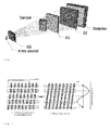
- a standard grating interferometer is shown in Fig. 1 , comprising a source grating G0, a phase grating G1 and an absorption grating G2.
- the use of source grating G0 is optional, depending on the spatial coherence properties of the X-ray source.
- the illumuation generated by the X-ray source is recorded by a detector disposed downstream of the absorption grating G2.
- the scanning approach is achieved by moving one of the gratings stepwise with respect to the recorded images along one period of the analyzer grating G1 in a direction perpendicular to the line of the phase grating G1.
- FIG. 2(a) schematically shows a sketch of a staggered grating G2, where the grating at a different lateral position covers each detector line.
- Figure 2(b) the same effect is achieved, when the analyzer grating G2 is tilted according to the present invention so that each line detector records a different phase step (red dots on the phase-stepping curve shown on the right).
- a staggered grating is used (see Fig. 2a ) [3], such that each line detector is covered by the grating at a different position in x direction
- the phase-stepping approach is mimicked by scanning the sample along y direction, without the need of moving the analyzer grating G2, and will end up having each line detector record a different phase step for each slice of the sample, as long as the grating lines are subsequently shifted by a distance ⁇ x , defined as: where n is the number of line detectors, so that the whole staggered grating is covering an integer number m of periods p 2 of the analyzer grating G2.
- the absorption, DPC and dark-field signals can be retrieved by standard FCA.
- a reference image i.e. no sample in the beam
- the procedure is started by acquiring a reference image and retrieving the background phase-stepping curve. Afterwards, a tilting angle is calculated based on the hardware (i.e. the number of line detectors disposed in the detector and the separation between the line detectors) and the number of periods p 2 to be covered. Subsequently, the analyzer grating G2 is tilted and the sample is moved along y direction (see Fig. 2 right side) by successive steps s until the signal corresponding to each slice has been recorded by the number of line detectors used for the calculations, so that a sample phase-stepping curve for each slice can be retrieved. Rearranging the acquired data, the absorption, DPC and dark-field signals can be reconstructed by performing FCA in two dimensions.
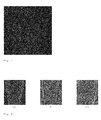
- FIG. 3 An example of the Moire fringe generated with this tilted grating method is shown in Fig. 3 and the corresponding reconstructed absorption, DPC and dark-field images acquired with the tilted-grating method are displayed in Fig. 4 .
- Grating-based X-ray imaging setups like the one shown in Figure 1 can generate three different signals: the conventional absorption contrast (AC) signal, the differential phase contrast (DPC) signal caused by refraction due to phase shifts, and the small-angle scattering contrast (SC) signal (also named dark-field signal) caused by scattering from inhomogeneities in the sample.
- AC absorption contrast
- DPC differential phase contrast
- SC small-angle scattering contrast
- Interferometer grating setups with two gratings (G1 and G2) or three gratings (G0, G1, and G2) can be used to record the deflection of the X-rays.
- the source needs to fulfill certain requirements regarding its spatial coherence.
- the source grating G0 is required, when the source size is bigger than p 2 *L / d , where p 2 is the period of G2, L is the distance between the source and G1, and d is the distance between G1 and G2.
- p 2 is the period of G2
- L is the distance between the source and G1
- d is the distance between G1 and G2.
- the three-grating setup is suited for use with incoherent X-ray sources, in particular with standard X-ray tubes.
- a phase-stepping approach is carried out.
- One of the gratings is displaced transversely to the incident beam whilst acquiring multiple images.
- the intensity signal at each pixel in the detector plane oscillates as a function of the displacement.
- the average value of the oscillation represents the AC.
- the phase of the oscillation can be directly linked to the wave-front phase profile and thus to the DPC signal.
- the amplitude of the oscillation depends on the scattering of X-rays in the object and thus yields the SC signal.
- the source grating G0 (if required) is the one closest to the X-ray source. It usually consists of a transmission grating of absorbing lines with the period p 0 . It can be replaced by a source that emits radiation only from lines with the same period.
- the phase grating G1 is placed further downstream of the X-ray source. It consists of lines with a period p 1 .
- the analyzer grating G2 is the one most downstream of the setup. It usually consists of a transmission grating of absorbing lines with the period p 2 . It can be replaced by a detector system that has a grating-like sensitivity with the same period.
- Two regimes of setups can be distinguished: In the so called “near-field regime” and the “Talbot regime”.
- the grating period p the grating period p , grating distances d and the x-ray wavelength A are chosen such that diffraction effects are negligible. In this case, all gratings need to consist of absorbing lines.
- the "Talbot regime” diffraction from the grating structures is significant.
- the phase grating G1 should consist of grating lines that are either absorbing or, preferentially, phase shifting. Several amounts of phase shift are possible, preferentially n/2 or multiples thereof.
- the grating periods must be matched to the relative distances between the gratings. In the case of setups in the "Talbot regime", the Talbot effect needs to be taken into account to obtain good contrast. The formulae for the grating periods and distances are described in [4].
- the sample is mostly placed between the source grating G0 and the phase grating G1 (or upstream of the phase grating G1 in the case of a two-grating set-up), however it can be advantageous to place it between the phase grating G1 and the analyzer grating G2 [5].
- the presented invention is relevant in all of the aforementioned cases, i.e. in the two- and three-gratings case, in the case of the "near-field regime” and the “Talbot regime", and for the sample placed upstream or downstream of G1.
Landscapes
- Health & Medical Sciences (AREA)
- Life Sciences & Earth Sciences (AREA)
- Engineering & Computer Science (AREA)
- Physics & Mathematics (AREA)
- Medical Informatics (AREA)
- General Health & Medical Sciences (AREA)
- Pathology (AREA)
- High Energy & Nuclear Physics (AREA)
- Heart & Thoracic Surgery (AREA)
- Animal Behavior & Ethology (AREA)
- Optics & Photonics (AREA)
- Biophysics (AREA)
- Radiology & Medical Imaging (AREA)
- Biomedical Technology (AREA)
- Veterinary Medicine (AREA)
- Molecular Biology (AREA)
- Surgery (AREA)
- Nuclear Medicine, Radiotherapy & Molecular Imaging (AREA)
- Public Health (AREA)
- Chemical & Material Sciences (AREA)
- Analytical Chemistry (AREA)
- Biochemistry (AREA)
- General Physics & Mathematics (AREA)
- Immunology (AREA)
- Spectroscopy & Molecular Physics (AREA)
- General Engineering & Computer Science (AREA)
- Analysing Materials By The Use Of Radiation (AREA)
- Toxicology (AREA)
Abstract
Among the existent X-ray phase-contrast modalities, grating interferometry appears as a very promising technique for commercial applications, since it is compatible with conventional X-ray tubes and is robust from a mechanical point of view. However, since applications such as medical imaging and homeland security demand covering a considerable field of view, the fabrication of large-area gratings, which is known to be challenging and expensive, would be needed. A scanning setup is a good solution for this issue, because it uses cheaper line instead of large-area 2D detectors and, therefore, would require smaller gratings. In such a setup, the phase-retrieval using the conventional phase-stepping approach would be very slow, so having a faster method to record the signals becomes fundamental. To tackle this problem, the present invention proposes a scanning-mode grating interferometer design, in which a grating is tilted to form Moiré fringes perpendicular to the grating lines. The sample is then translated along the fringes, so each line detector records a different phase step for each slice of the sample.
Description
- The present invention relates to a method and a system to retrieve absorption, DPC and dark field signals obtained by a grating interferometer.
- Grating interferometry constitutes a very promising technique for commercial X-ray phase-contrast applications, since it works with traditional X-ray tubes, is mechanically robust and has modest requirements for mono-chromaticity and spatial coherence. In the last few years, several exciting applications of this technique have been reported, ranging from material inspection to medical imaging.
- To carry out the transition of grating interferometry from the laboratory to the commercial setting, it has to be tailored to cover a large field of view (FOV) and allow reasonable exposure times. To fulfill these requirements, a scanning setup would be an excellent choice, since it requires line instead of 2D detectors and would avoid the fabrication of large-area gratings, which might be laborious and pricy. On the other hand, in order to retrieve different contrast signals, conventional grating interferometry requires a phase-stepping procedure, in which one of the gratings is translated stepwise (in sub-micron scale) and an image is acquired for each step. This procedure is time-consuming in general and demands high system stability and accuracy, so it constitutes a major problem for the implementation of grating interferometry in a commercial setting. A scanning-mode method able to "hard-code" the phase-stepping procedure into a one-dimension scan [1,] can fundamentally solve the problem.
- In this regard, Kottler et al [2] introduced a scanning-mode grating interferometry setup. They propose a method in which a Moire fringe parallel to the grating lines is generated by slightly changing the theoretical inter-grating distance. In this arrangement, equidistantly distributed lines of the detector correspond to different relative positions of the phase and absorption gratings, which can be regarded as phase-steps. Therefore, by translating the sample in a direction perpendicular to the fringe orientation, a phase-stepping curve can be retrieved and Fourier-Component Analysis (FCA) can be used to reconstruct the signals.
- Another possibility to solve this issue is to use a staggered grating, so that the grating is located at a different lateral position for each line detector, and a phase stepping curve can be retrieved by scanning the sample in a direction perpendicular to the grating lines. However, this approach implies the fabrication of gratings with a novel design which will be hard to align, and kept as such, with the line detectors.
- As mentioned above, to transfer the X-ray grating interferometry technology to a commercial setting, it is necessary to make it suitable to image large field-of-views. To achieve this goal while using the current grating interferometry implementation, large-area gratings would be needed, but they are difficult and pricy to fabricate. Therefore, it would be ideal to avoid the fabrication of this kind of gratings.
- Managing to integrate the grating interferometer technology into a scanning setup certainly avoids this issue. However, its integration involves the development of a new signal retrieval method, because the conventional retrieval method would be inefficient in this setup.
- It is therefore the objective of the present invention to provide a system and a method for retrieving absorption, DPC and dark field signals obtained by a grating interferometer.
- This objective is achieved according to the present invention by a method and a system that use a tilted-grating-based scanning method for grating interferometryas given in claim 1 for the method and claim 7 for the system. The general idea is to generate a Moire fringe perpendicular to the grating lines by tilting one of the gratings, so that each line detector of the detector ends up recording a different phase step as the sample is translated during the scan.
- Preferred embodiments of the present invention are listed in claims 2 to 6 and 8 to 10.
- Preferred examples of the present invention are hereinafter described with reference to the attached drawings which depict in:
- Fig. 1
- schematically a sketch of an X-ray grating interferometer having a tilted grating;
- Fig. 2
- schematically the essential feature of the tilted grating in a tilted-grating method;
- Fig. 3
- schematically a Moire pattern generated with the tilted-grating method; and
- Fig. 4
- schematically the absorption, DPC and dark-field images acquired with the tilted-grating method.
- A standard grating interferometer is shown in
Fig. 1 , comprising a source grating G0, a phase grating G1 and an absorption grating G2. The use of source grating G0 is optional, depending on the spatial coherence properties of the X-ray source. During the scanning of a sample, the illumuation generated by the X-ray source is recorded by a detector disposed downstream of the absorption grating G2. The scanning approach is achieved by moving one of the gratings stepwise with respect to the recorded images along one period of the analyzer grating G1 in a direction perpendicular to the line of the phase grating G1. - The general idea behind the tilted-grating design is illustrated in
Fig. 2. Figure 2(a) schematically shows a sketch of a staggered grating G2, where the grating at a different lateral position covers each detector line. InFigure 2(b) the same effect is achieved, when the analyzer grating G2 is tilted according to the present invention so that each line detector records a different phase step (red dots on the phase-stepping curve shown on the right). - If a staggered grating is used (see
Fig. 2a ) [3], such that each line detector is covered by the grating at a different position in x direction, the phase-stepping approach is mimicked by scanning the sample along y direction, without the need of moving the analyzer grating G2, and will end up having each line detector record a different phase step for each slice of the sample, as long as the grating lines are subsequently shifted by a distance δx, defined as:
Fig. 2b . Assuming the present line detectors are separated by a distance D, the tilting angle θ can be calculated as:
- To compensate for the beam divergence, the sample-translation step s must be adjusted to:

where L is the source-to-G1 distance and d represents the inter-grating distance. Afterwards, the absorption, DPC and dark-field signals can be retrieved by standard FCA. A reference image (i.e. no sample in the beam) has to be acquired as well in order to subtract the background phase distribution, like in the phase-stepping approach. - Recapitulating, the procedure is started by acquiring a reference image and retrieving the background phase-stepping curve. Afterwards, a tilting angle is calculated based on the hardware (i.e. the number of line detectors disposed in the detector and the separation between the line detectors) and the number of periods p2 to be covered. Subsequently, the analyzer grating G2 is tilted and the sample is moved along y direction (see
Fig. 2 right side) by successive steps s until the signal corresponding to each slice has been recorded by the number of line detectors used for the calculations, so that a sample phase-stepping curve for each slice can be retrieved. Rearranging the acquired data, the absorption, DPC and dark-field signals can be reconstructed by performing FCA in two dimensions. - An example of the Moire fringe generated with this tilted grating method is shown in
Fig. 3 and the corresponding reconstructed absorption, DPC and dark-field images acquired with the tilted-grating method are displayed inFig. 4 . Grating-based X-ray imaging setups like the one shown inFigure 1 can generate three different signals: the conventional absorption contrast (AC) signal, the differential phase contrast (DPC) signal caused by refraction due to phase shifts, and the small-angle scattering contrast (SC) signal (also named dark-field signal) caused by scattering from inhomogeneities in the sample. - Interferometer grating setups with two gratings (G1 and G2) or three gratings (G0, G1, and G2) can be used to record the deflection of the X-rays. In the case of a two-grating setup, the source needs to fulfill certain requirements regarding its spatial coherence. The source grating G0 is required, when the source size is bigger than p2*L/d, where p2 is the period of G2, L is the distance between the source and G1, and d is the distance between G1 and G2. In a three-grating setup no spatial coherence is required. Therefore, the three-grating setup is suited for use with incoherent X-ray sources, in particular with standard X-ray tubes.
- To separate the conventional attenuation contrast (AC) from the DPC and SC contrast, a phase-stepping approach is carried out. One of the gratings is displaced transversely to the incident beam whilst acquiring multiple images. The intensity signal at each pixel in the detector plane oscillates as a function of the displacement. The average value of the oscillation represents the AC. The phase of the oscillation can be directly linked to the wave-front phase profile and thus to the DPC signal. The amplitude of the oscillation depends on the scattering of X-rays in the object and thus yields the SC signal.
- For the (two or three) gratings, several variations have been proposed and applied. The source grating G0 (if required) is the one closest to the X-ray source. It usually consists of a transmission grating of absorbing lines with the period p0 . It can be replaced by a source that emits radiation only from lines with the same period. The phase grating G1 is placed further downstream of the X-ray source. It consists of lines with a period p1 . The analyzer grating G2 is the one most downstream of the setup. It usually consists of a transmission grating of absorbing lines with the period p2 . It can be replaced by a detector system that has a grating-like sensitivity with the same period.
- Two regimes of setups can be distinguished: In the so called "near-field regime" and the "Talbot regime". In the "near-field regime", the grating period p, grating distances d and the x-ray wavelength A are chosen such that diffraction effects are negligible. In this case, all gratings need to consist of absorbing lines. In the "Talbot regime", diffraction from the grating structures is significant.
- Here, the phase grating G1 should consist of grating lines that are either absorbing or, preferentially, phase shifting. Several amounts of phase shift are possible, preferentially n/2 or multiples thereof. The grating periods must be matched to the relative distances between the gratings. In the case of setups in the "Talbot regime", the Talbot effect needs to be taken into account to obtain good contrast. The formulae for the grating periods and distances are described in [4].
- It has to be noted that a sharp distinction between the two regimes is not easily given, as the exact criterion depends on the duty cycle of the grating structure, and whether the gratings are absorbing or phase shifting. E.g., for a grating with absorbing lines and a duty cycle of 0.5, the condition for the "near field regime" is d ≥ p2 /2λ.
- The sample is mostly placed between the source grating G0 and the phase grating G1 (or upstream of the phase grating G1 in the case of a two-grating set-up), however it can be advantageous to place it between the phase grating G1 and the analyzer grating G2 [5].
- The presented invention is relevant in all of the aforementioned cases, i.e. in the two- and three-gratings case, in the case of the "near-field regime" and the "Talbot regime", and for the sample placed upstream or downstream of G1.
- Intensity curves (with and without sample) are usually obtained with "phase stepping" methods or alternative techniques. Defining for each pixel on the detector the mean, phase and visibility of the intensity curve with sample as Is ,Φs ,Vs , and without sample as Ib ,Φ b ,Vb , yields:


- For both the AC signal and SC signal, the valid data range is [0,+∞], while for the DPC it is [-π,+π]. Images obtained by plotting such signals are all perfectly registered.
- A similar way to generate these multiple information signals can be found in diffraction enhanced imaging where the equivalent of the intensity curve is named the rocking curve.
-
- [1] E. Roessl, H. Daerr, T. Koehler, G. Martens and U. van Stevendaal, "Slit-scanning differential phase-contrast mammography: First experimental results," Proc.SPIE 9033, 90330C (2014).
- [2] C. Kottler, F. Pfeiffer, O. Bunk, C. Grünzweig, C. David, "Grating interferometer based scanning setup for hard X-ray phase contrast imaging," Rev. Sci. Instrum. 78, 043710 (2007).
- [3] C. David and F. Pfeiffer, "X-ray interferometer for phase contrast imaging," Patent
WO 2008/006470 A1 (17. Jan, 2008 ). - [4] T. Weitkamp, C. David, C. Kottler et al.,"Tomography with grating interferometers at low-brilliance sources", 6318, 6318S (2006).
- [5] C. David, Optimierte Anordnung von Gittern fur die Phasenkontrastbildgebung im Röntgenbereich, Europäische Patentanmeldung
EP 2 168 488 A1 .
Claims (10)
- A method to retrieve absorption, DPC and dark field signals from a Moire fringe pattern obtained by detuning a grating interferometer system comprising an X-ray source, at least a phase grating and an analyzer grating and a line sensitive detector by tilting one of the gratings and scanning either the sample or the grating interferometer system along this Moire fringe pattern.
- The method according to claim 1, wherein a Moire fringe pattern of a desired period is produced by tilting one of the gratings by a predetermined angle.
- The method according to claim 2, wherein the tilting angle is calculated using the following information: the period p 2 of the analyzer G2 grating, the number n of detector lines, the number m of periods p2 that are to be covered and the separation D between the detector lines of said line sensitive detector, and employing these formulas:


- The method according to any of the preceding claims, wherein the reference and sample data acquired with said grating interferometer system are used to retrieve absorption, DPC and dark-field signals either by Fourier Component Analysis or similar methods.
- The method according to any of the preceding claims, wherein in a grating interferometer system having a phase grating and an analyzer grating one of the two gratings is tilted or in a grating interferometer system having a source grating, a phase grating and an analyzer grating either only the phase grating G1 or only the analyzer grating G2 or the pair of source grating and phase grating or the pair of phase grating and analyzer grating is tilted.
- A method according to any of the preceding claims, wherein compatible with radiography, tomo-synthesis and computed tomography either the sample or the grating interferometer system is rotated to acquire multiples views.
- A grating interferometer system for obtaining the absorption, DPC and dark-field data from quantitative X-ray images from a sample, comprising:a. an X-ray source;b. a phase grating and an analyzer grating or a source grating, a phase grating and an analyzer grating;c. a position-sensitive detector, preferably a line sensitive detector;d. means for recording the images of the detector;e. means for evaluating the intensities for each pixel in a series of images, in order to identify the characteristics of the object for each individual pixel as an absorption-dominated pixel and/or a DPC-dominated pixel and/or an X-ray dark-field dominated pixel;f. means to tilt either the phase grating or the analyzer grating by a predetermined angle; andg. means to move the sample or the x-ray source, the gratings and the detector to perform the scanning of the probe.
- The system according to claims 7, wherein the phase grating is a line grating, either an absorption grating or a phase grating, that is a low-absorption grating but generating a considerable X-ray phase shift, the latter preferably of n or odd multiples thereof.
- The system according to claims 7 or 8, wherein the analyzer grating is a line grating having a high X-ray absorption contrast with its period being the same as that of the self-image of phase grating, wherein the analyzer grating is preferably placed closely in front of the detector with its lines parallel to those of phase grating, before tilting the phase grating or the analyzer grating.
- The system according to any of the preceding claims 7 to 10, wherein for near-field-regime operation, the distance between the gratings is chosen freely within the regime,
and for the Talbot-regime is chosen according to
where n=1,3,5......, and
where l=1,2,3......, Dn is an odd fractional Talbot distance when the parallel X-ray beam is used, while D n,sph is that when the fan or cone X-ray beam is used and L is the distance between the source and the phase grating.
Priority Applications (4)
| Application Number | Priority Date | Filing Date | Title |
|---|---|---|---|
| EP14167372.3A EP2942619A1 (en) | 2014-05-07 | 2014-05-07 | Tilted-grating approach for scanning-mode X-ray grating interferometry |
| EP15707898.1A EP3140641B1 (en) | 2014-05-07 | 2015-02-25 | Tilted-grating approach for scanning-mode x-ray grating interferometry |
| US15/309,222 US10433799B2 (en) | 2014-05-07 | 2015-02-25 | Tilted-grating approach for scanning-mode X-ray grating interferometry |
| PCT/EP2015/053909 WO2015169463A1 (en) | 2014-05-07 | 2015-02-25 | Tilted-grating approach for scanning-mode x-ray grating interferometry |
Applications Claiming Priority (1)
| Application Number | Priority Date | Filing Date | Title |
|---|---|---|---|
| EP14167372.3A EP2942619A1 (en) | 2014-05-07 | 2014-05-07 | Tilted-grating approach for scanning-mode X-ray grating interferometry |
Publications (1)
| Publication Number | Publication Date |
|---|---|
| EP2942619A1 true EP2942619A1 (en) | 2015-11-11 |
Family
ID=50693489
Family Applications (2)
| Application Number | Title | Priority Date | Filing Date |
|---|---|---|---|
| EP14167372.3A Withdrawn EP2942619A1 (en) | 2014-05-07 | 2014-05-07 | Tilted-grating approach for scanning-mode X-ray grating interferometry |
| EP15707898.1A Active EP3140641B1 (en) | 2014-05-07 | 2015-02-25 | Tilted-grating approach for scanning-mode x-ray grating interferometry |
Family Applications After (1)
| Application Number | Title | Priority Date | Filing Date |
|---|---|---|---|
| EP15707898.1A Active EP3140641B1 (en) | 2014-05-07 | 2015-02-25 | Tilted-grating approach for scanning-mode x-ray grating interferometry |
Country Status (3)
| Country | Link |
|---|---|
| US (1) | US10433799B2 (en) |
| EP (2) | EP2942619A1 (en) |
| WO (1) | WO2015169463A1 (en) |
Cited By (5)
| Publication number | Priority date | Publication date | Assignee | Title |
|---|---|---|---|---|
| CN107024490A (en) * | 2016-01-29 | 2017-08-08 | 中国科学院高能物理研究所 | Single exposure grating shearing imaging device and data acquisition and information extracting method |
| CN109765250A (en) * | 2019-01-31 | 2019-05-17 | 南京森林警察学院 | A kind of efficient drugs CT scan detection device |
| US10788309B2 (en) | 2016-04-01 | 2020-09-29 | The University Of Liverpool | Frequency-domain optical interferometry imaging apparatus and method for astigmatistic bi-focal illumination imaging of an eye |
| CN115774296A (en) * | 2022-11-16 | 2023-03-10 | 梁可心 | Anti-electromagnetic interference electronic grating manufacturing method |
| CN116879326A (en) * | 2023-09-07 | 2023-10-13 | 浙江大学杭州国际科创中心 | X-ray optical phase contrast imaging system and method based on multi-frequency stripes |
Families Citing this family (7)
| Publication number | Priority date | Publication date | Assignee | Title |
|---|---|---|---|---|
| US10578563B2 (en) * | 2012-12-21 | 2020-03-03 | Carestream Health, Inc. | Phase contrast imaging computed tomography scanner |
| JP2016106721A (en) * | 2014-12-03 | 2016-06-20 | キヤノン株式会社 | Image processing device and image processing method |
| EP3446630A1 (en) | 2017-08-23 | 2019-02-27 | Koninklijke Philips N.V. | Device and method for phase stepping in phase contrast image acquisition |
| EP3498170A1 (en) * | 2017-12-12 | 2019-06-19 | Koninklijke Philips N.V. | Device and method for aligning an x-ray grating to an x-ray radiation source, and x-ray image acquisition system |
| CN110868932B (en) * | 2017-12-25 | 2024-02-09 | 株式会社岛津制作所 | Radiographic phase difference imaging device |
| CN109243661B (en) * | 2018-09-29 | 2020-07-28 | 同济大学 | A sidewall inclined X-ray layered multilayer film grating structure |
| CN110068584A (en) * | 2019-03-15 | 2019-07-30 | 中国工程物理研究院流体物理研究所 | Scan-type X-ray grating interference imaging system and method |
Citations (5)
| Publication number | Priority date | Publication date | Assignee | Title |
|---|---|---|---|---|
| WO2008006470A1 (en) | 2006-07-12 | 2008-01-17 | Paul Scherrer Institut | X-ray interferometer for phase contrast imaging |
| EP2168488A1 (en) | 2008-09-30 | 2010-03-31 | Siemens Aktiengesellschaft | X-ray CT system for x-ray phase contrast and/or x-ray dark field imaging |
| US20110235780A1 (en) * | 2010-03-29 | 2011-09-29 | Fujifilm Corporation | Radiation imaging system and offset correction method thereof |
| US20110243305A1 (en) * | 2010-03-30 | 2011-10-06 | Fujifilm Corporation | Radiographic system, radiographic method and computer readable medium |
| US20130028378A1 (en) * | 2011-07-29 | 2013-01-31 | The Johns Hopkins University | Differential phase contrast x-ray imaging system and components |
Family Cites Families (1)
| Publication number | Priority date | Publication date | Assignee | Title |
|---|---|---|---|---|
| EP1731099A1 (en) * | 2005-06-06 | 2006-12-13 | Paul Scherrer Institut | Interferometer for quantitative phase contrast imaging and tomography with an incoherent polychromatic x-ray source |
-
2014
- 2014-05-07 EP EP14167372.3A patent/EP2942619A1/en not_active Withdrawn
-
2015
- 2015-02-25 EP EP15707898.1A patent/EP3140641B1/en active Active
- 2015-02-25 US US15/309,222 patent/US10433799B2/en active Active
- 2015-02-25 WO PCT/EP2015/053909 patent/WO2015169463A1/en not_active Ceased
Patent Citations (5)
| Publication number | Priority date | Publication date | Assignee | Title |
|---|---|---|---|---|
| WO2008006470A1 (en) | 2006-07-12 | 2008-01-17 | Paul Scherrer Institut | X-ray interferometer for phase contrast imaging |
| EP2168488A1 (en) | 2008-09-30 | 2010-03-31 | Siemens Aktiengesellschaft | X-ray CT system for x-ray phase contrast and/or x-ray dark field imaging |
| US20110235780A1 (en) * | 2010-03-29 | 2011-09-29 | Fujifilm Corporation | Radiation imaging system and offset correction method thereof |
| US20110243305A1 (en) * | 2010-03-30 | 2011-10-06 | Fujifilm Corporation | Radiographic system, radiographic method and computer readable medium |
| US20130028378A1 (en) * | 2011-07-29 | 2013-01-31 | The Johns Hopkins University | Differential phase contrast x-ray imaging system and components |
Non-Patent Citations (3)
| Title |
|---|
| C. KOTTLER; F. PFEIFFER; O. BUNK; C. GRUNZWEIG; C. DAVID: "Grating interferometer based scanning setup for hard X-ray phase contrast imaging", REV. SCI. INSTRUM., vol. 78, 2007, pages 043710 |
| E. ROESSL; H. DAERR; T. KOEHLER; G. MARTENS; U. VAN STEVENDAAL: "Slit-scanning differential phase-contrast mammography: First experimental results", PROC.SPIE, vol. 9033, 2014, pages 90330C, XP060031478, DOI: doi:10.1117/12.2043631 |
| T. WEITKAMP; C. DAVID; C. KOTTLER ET AL., TOMOGRAPHY WITH GRATING INTERFEROMETERS AT LOW-BRILLIANCE SOURCES, vol. 6318, 2006, pages 6318S |
Cited By (9)
| Publication number | Priority date | Publication date | Assignee | Title |
|---|---|---|---|---|
| CN107024490A (en) * | 2016-01-29 | 2017-08-08 | 中国科学院高能物理研究所 | Single exposure grating shearing imaging device and data acquisition and information extracting method |
| CN107024490B (en) * | 2016-01-29 | 2019-07-05 | 中国科学院高能物理研究所 | Single exposure grating shearing imaging device and data acquisition and information extracting method |
| US10788309B2 (en) | 2016-04-01 | 2020-09-29 | The University Of Liverpool | Frequency-domain optical interferometry imaging apparatus and method for astigmatistic bi-focal illumination imaging of an eye |
| US11415407B2 (en) | 2016-04-01 | 2022-08-16 | The University Of Liverpool | Frequency-domain optical interferometry imaging apparatus and method for astigmatistic bi-focal illumination imaging of an eye |
| CN109765250A (en) * | 2019-01-31 | 2019-05-17 | 南京森林警察学院 | A kind of efficient drugs CT scan detection device |
| CN115774296A (en) * | 2022-11-16 | 2023-03-10 | 梁可心 | Anti-electromagnetic interference electronic grating manufacturing method |
| CN115774296B (en) * | 2022-11-16 | 2023-07-18 | 京东方科技集团股份有限公司 | A kind of anti-electromagnetic interference electronic grating manufacturing method |
| CN116879326A (en) * | 2023-09-07 | 2023-10-13 | 浙江大学杭州国际科创中心 | X-ray optical phase contrast imaging system and method based on multi-frequency stripes |
| CN116879326B (en) * | 2023-09-07 | 2023-12-19 | 浙江大学杭州国际科创中心 | X-ray optical phase contrast imaging system and method based on multi-frequency stripes |
Also Published As
| Publication number | Publication date |
|---|---|
| WO2015169463A1 (en) | 2015-11-12 |
| US20170082559A1 (en) | 2017-03-23 |
| EP3140641B1 (en) | 2018-01-31 |
| US10433799B2 (en) | 2019-10-08 |
| EP3140641A1 (en) | 2017-03-15 |
Similar Documents
| Publication | Publication Date | Title |
|---|---|---|
| US10433799B2 (en) | Tilted-grating approach for scanning-mode X-ray grating interferometry | |
| EP2585817B1 (en) | A method for x-ray phase contrast and dark-field imaging using an arrangement of gratings in planar geometry | |
| US8972191B2 (en) | Low dose single step grating based X-ray phase contrast imaging | |
| US10058300B2 (en) | Large FOV phase contrast imaging based on detuned configuration including acquisition and reconstruction techniques | |
| EP2038641B1 (en) | X-ray interferometer for phase contrast imaging | |
| US10074451B2 (en) | X-ray interferometer | |
| JP5961614B2 (en) | Grating apparatus for phase contrast imaging, apparatus for phase contrast imaging, X-ray system having the apparatus, and method of using the apparatus | |
| US8855265B2 (en) | Correction method for differential phase contrast imaging | |
| US20130279659A1 (en) | Method and a system for image integration using constrained optimization for phase contrast imaging with an arragement of gratings | |
| US20140169698A1 (en) | Method for image fusion based on principal component analysis | |
| JP2013524897A (en) | X-ray source diffraction grating step imaging system and imaging method | |
| EP3169239B1 (en) | Phase contrast imaging x-ray device provided with at least one movable grating | |
| EP3344979B1 (en) | Dual phase grating interferometer for x-ray phase contrast imaging | |
| Wang et al. | At-wavelength metrology using the moiré fringe analysis method based on a two dimensional grating interferometer |
Legal Events
| Date | Code | Title | Description |
|---|---|---|---|
| PUAI | Public reference made under article 153(3) epc to a published international application that has entered the european phase |
Free format text: ORIGINAL CODE: 0009012 |
|
| AK | Designated contracting states |
Kind code of ref document: A1 Designated state(s): AL AT BE BG CH CY CZ DE DK EE ES FI FR GB GR HR HU IE IS IT LI LT LU LV MC MK MT NL NO PL PT RO RS SE SI SK SM TR |
|
| AX | Request for extension of the european patent |
Extension state: BA ME |
|
| STAA | Information on the status of an ep patent application or granted ep patent |
Free format text: STATUS: THE APPLICATION IS DEEMED TO BE WITHDRAWN |
|
| 18D | Application deemed to be withdrawn |
Effective date: 20160512 |