EP2942236A1 - Commercial vehicle cab with a mobile storage unit - Google Patents
Commercial vehicle cab with a mobile storage unit Download PDFInfo
- Publication number
- EP2942236A1 EP2942236A1 EP15000387.9A EP15000387A EP2942236A1 EP 2942236 A1 EP2942236 A1 EP 2942236A1 EP 15000387 A EP15000387 A EP 15000387A EP 2942236 A1 EP2942236 A1 EP 2942236A1
- Authority
- EP
- European Patent Office
- Prior art keywords
- transport container
- door
- suspension
- cabin
- car door
- Prior art date
- Legal status (The legal status is an assumption and is not a legal conclusion. Google has not performed a legal analysis and makes no representation as to the accuracy of the status listed.)
- Granted
Links
- 239000000725 suspension Substances 0.000 claims abstract description 43
- 230000001419 dependent effect Effects 0.000 description 1
- 239000010813 municipal solid waste Substances 0.000 description 1
- 238000005406 washing Methods 0.000 description 1
Images


Classifications
-
- B—PERFORMING OPERATIONS; TRANSPORTING
- B60—VEHICLES IN GENERAL
- B60R—VEHICLES, VEHICLE FITTINGS, OR VEHICLE PARTS, NOT OTHERWISE PROVIDED FOR
- B60R7/00—Stowing or holding appliances inside vehicle primarily intended for personal property smaller than suit-cases, e.g. travelling articles, or maps
- B60R7/04—Stowing or holding appliances inside vehicle primarily intended for personal property smaller than suit-cases, e.g. travelling articles, or maps in driver or passenger space, e.g. using racks
- B60R7/046—Stowing or holding appliances inside vehicle primarily intended for personal property smaller than suit-cases, e.g. travelling articles, or maps in driver or passenger space, e.g. using racks mounted on door
Definitions
- the invention relates to a utility vehicle cabin with a mobile storage space according to the preamble of claim 1.
- a transport container especially a suitcase in the vehicle cabin.
- the transport container such as a bag or a hard shell case with pull-out handle (trolley)
- the transport container is lifted up with the front passenger's door open and placed on the passenger seat.
- the suitcase is therefore taken regularly by the driver from the seat and placed on the floor or a rear deck, but where he is difficult to access for use.
- stowage spaces that are permanently integrated in a utility vehicle cabin are known as lockable compartments, drawers, etc., but these are not available as mobile stowage spaces for external loading.
- the object of the invention is to develop a commercial vehicle cabin with a mobile storage space so that a position fixable additional storage space is provided in conjunction with a loading aid available.
- the mobile storage space is formed by at least one transport container, which with a fastening device, preferably by means of an input and / or suspension device, on a door inside a - preferably passenger side - Cabin door can be fixed, in particular releasably fixed and / or can be suspended.
- the transport container is dimensioned in this case and the fastening device is designed and arranged such that the transport container fixed to the car door is pivoted into the cabin with the car door closed over a seat surface, in particular above a passenger seat surface.
- the loading of the cabin with the transport container can thus be easily and conveniently performed by a person hangs, for example, with the passenger door open the transport container, for example by means of the suspension device on the inside of the door. Subsequently, the person can enter the cabin without interference by the transport container and pull the door, whereby the transport container pivots over the passenger seat surface and fixed in position is ready to hand.
- a suitcase is used as a transport container, which can be designed as a hard case and / or mobile suitcase and / or suitcase with pull-out (trolley).
- the case wall or a luggage rack to which the suitcase-side part of the suspension device is attached should be formed correspondingly stable for the holding function.
- the transport container but also by a bag, in particular a travel bag, be formed.
- a suitable transport container size for the loading according to the invention by means of the pivotable vehicle door preferably corresponds approximately to the dimensions of aircraft luggage (hand luggage), in particular with a height of up to 56 cm, a width of up to 45 cm and a depth of up to 25 cm.
- the transport container may be designed for a defined overall weight corresponding to the aircraft free luggage (hand luggage), for example, of a maximum of 12 kg, in particular of 5 to 12 kg.
- the fastening device is in several parts, in particular in two parts, releasably designed as an up and / or suspension device and has these a Einberichtteil on the transport container and a support member on the car door.
- the suspension part on the transport container is preferably mounted approximately in the middle of the rear side of the transport container.
- the suspension part on the transport container as a suspension element for example as a hooks, optionally be folded, with as an associated support member on the cabin door, the inner door railing is used for hanging.
- This embodiment is simple and very inexpensive and requires no additional attachments to the vehicle door.
- the suspension element can be folded in and / or into the transport container, for example, and / or can be retracted there.
- the support member on the car door is a, preferably vertically aligned, mounting rail part, which is fixedly attached to the car door in height of the door parapet or attachable there.
- the mounting rail part by means of a hook on the inner door parapet be designed to be suspended.
- an associated rail receiving part is attached, with which the transport container on the mounting rail to a lock / stop can be plugged.
- the mounting rail can be designed in particular as a T-rail or dovetail rail.
- the transport container preferably a suitcase, a, for example U-shaped, pull-out, wherein the Einberichtteil, for example a hook, on the pull-out (for example, on the handle part of the pull-out) is mounted and the associated support member on the Cabin door, preferably on the upper door frame of the car door, is used for hanging.
- the suitcase is preferably hung on the open passenger door with extended pull-out on the upper Mosrrahmen. Subsequently, the suitcase is lifted upwards as far as a defined position, while the pull-out handle is pushed in to a position which may be determined by a catch, so that the suitcase is positioned at a height above the passenger seat surface. Then you can get in and the passenger door closed.
- At least one further support part which is compatible with a suspension part on the transport container, be suitable Place the cabin to arrange.
- this may be a mounting rail part for pushing on an associated rail receiving part of the transport container for a stable mounting.
- a particularly suitable location is the back of a folding forward seat backrest, in particular a passenger seat backrest.
- the transport container in particular a suitcase, can be removed to its loading in the cabin of the passenger door and attached to the support member on the seat back. If the backrest is folded forward, then the case is ready for use within reach. If a lounger is located behind the backrest, its use is limited only slightly by a suitcase on the backrest, especially when the seat is displaced forward as a whole, or the backrest is folded forward.
- a support member may also be attached to the underside of an upper deck, so that then hangs the transport container under the upper deck. If necessary and possibly additionally, the transport container can also be hung here with a container-side hook on the front edge of the deck.
- a support member may also be mounted on the inside of a roof side wall above the car door, so that there a transport container, in particular a suitcase can be provided transversely or upright as a stable, fixed storage space available.
- the suspension device can advantageously be secured with an actuatable lock, wherein in particular a mounting rail part can preferably have a spring-biased, actuatable push-button lock.
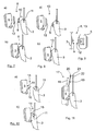
- Fig. 1 is a partial perspective view of a grooved vehicle as a truck 1 shown with a driver's cab 2 and an open passenger side cabin door. 3
- a suitcase 5 In front of the open cabin door 3 is a person 4 as a driver, a suitcase 5 by means of a suspension device (see Fig. 7 to 11 ) hangs on the inside of the door so that the underside of the case lies at a height above the passenger seat.
- the case 5 is only an example of a preferred transport container; In principle, any other suitable transport container could be used in the following analogous manner instead of the suitcase.
- Fig. 2 is shown how the person 4 comfortably and without interference by the hinged case 5 enters, which then the situation after Fig. 3 that results in Fig. 4 is shown again from the cabin inside with a view of the passenger seat 6.
- Fig. 5 is shown how the person 4 (see the arm 7) pulls the car door 3.
- Fig. 6 the state is shown when the car door 3 is closed from the driver's side.
- the hinged to the car door 3 case 5 is seen so pivoted together with the car door 3 via the passenger seat 6, that the bottom of the case 5 comes to rest above the passenger seat surface.
- Fig. 7 a first embodiment of a suspension device 8 is shown, wherein in Fig. 7a their components separated and in Fig. 7b are shown assembled.
- the suspension device 8 is formed in two parts and consists of a mounting rail part 9 in the form of a T-rail part with an upper hooks 10 in the shape of the inner door railing 11 of the cabin door 3, where the mounting rail part 9 in the mounted position (Fig. Fig. 7b ) is mounted.
- a rail support member 9 associated with the rail receiving part 12 is attached to the the case 5 attached to the mounting rail part 9 and the car door 3 accordingly Fig. 7b is held.
- Fig. 8 a second embodiment of a suspension device 13 is shown, which is similar to the embodiment of FIG Fig. 7 is, with the difference that the mounting rail part 9 here (without hooks 10) is firmly attached to the inside of the door of the car door 3.
- Fig. 9 is a top view of the case 5 with the rail receiving part 12 and the associated T-shaped mounting rail part 9 according to the embodiments according to Fig. 8 and 13 ,
- a third embodiment of a suspension device 14 is shown, in which at the back of the suitcase 5 in the central region a suspension hook 15 is arranged, which is designed fold-out (double arrow 16). With the hook 15 of the case 5 can be hung directly on the door railing 11 ( Fig. 10b ), so that the door parapet 11 is used here directly as a supporting part on the car door 3.
- a fourth embodiment of a suspension device 17 is shown in conjunction with a case 5, which here has a U-shaped pull-out handle 18 (pull-out function represented by double arrow 19).
- the handle part 20 as a U-base is here equipped with a suspension hook 21, with which the case 5 is suspended at (partially) ejected pull-out handle 18 on the upper door frame 22 of the cabin door 3.
- the fourth embodiment of the suspension device 17 with the U-shaped pull-out handle 18 is shown by dashed lines.
- the hanging operation of the case 5 on the car door 3 can proceed in such a way that, when the pull-out handle 18 is fully extended, the hanging hook 21 is hung on the upper door frame 22 (dashed line in FIG Fig.
- the case 5 is raised and the pull-out handle 18 with its guide rods pushed so far bite the case 5 is positioned at the required height above the passenger seat surface. Subsequently, the car door 3 can be closed and the case 5 can be swung over the passenger seat surface.
- the case 5 can be removed from the car door 3 and fixedly attached to the back in the upper part of a folding backrest 23 of the passenger seat 6.
- a horizontally extending, T-shaped mounting rail part 24 (corresponding to the mounting rail part 9 of Fig. 9 ) appropriate, on the case 5 with its rail receiving part 12 can be plugged.
- the mounting rail part 24 has a spring-biased, actuatable push-button lock 25, with which the case 5 can be secured in its position. With such a push-button lock 25 and the mounting rail part 9 can be made Fig. 9 be equipped.
- Fig. 14 is the arrangement after Fig. 12 shown at forward folded backrest 23.
- the suitcase 5 is such that its cover flap 26 can be conveniently opened and its contents can be utilized.
- Fig. 15 is the arrangement after Fig. 12 shown with the case 5 at the back of the backrest 23, wherein it is followed by a rear lower lounger 27.
- legs 28 of a person is illustrated that the legroom on the deck 27 is limited only slightly by the case 5, especially when the passenger seat 6 is adjusted with its backrest 23 in total to the front and / or the backrest 23 folded forward becomes.
- a suitable mounting location for the case 5 is shown on the underside of an upper couch, whereby a corresponding mounting rail part is also to be arranged there or, if appropriate, a suspension device with hooks can be formed.
- a further alternative or additional possibility for the stowage of the case 5 is shown on an inner roof side wall 30 above the cabin door 3, wherein a corresponding mounting rail part is also to be attached here.
- the case 5 can be transversely or optionally upright (dashed lines drawn) kept and stowed.
Landscapes
- Engineering & Computer Science (AREA)
- Mechanical Engineering (AREA)
- Vehicle Step Arrangements And Article Storage (AREA)
Abstract
Die Erfindung betrifft eine Nutzfahrzeugkabine mit einem mobilen Stauraum. Erfindungsgemäß ist der mobile Stauraum durch wenigstens ein Transportbehältnis (5) gebildet, wobei das Transportbehältnis (5) mit einer Befestigungseinrichtung (8; 13; 14; 17), insbesondere mit einer Auf- und/oder Einhängevorrichtung, an einer Türinnenseite einer, vorzugsweise beifahrerseitigen, Kabinentür (3) festlegbar ist, insbesondere lösbar festlegbar und/oder einhängbar ist, und wobei das Transportbehältnis (5) so dimensioniert und die Befestigungseinrichtung (8; 13; 14; 17) so ausgebildet und angeordnet ist, dass das an der Kabinentür (3) festgelegte Transportbehältnis (5) bei geschlossener Kabinentür (3) über einer Sitzfläche, insbesondere über der Beifahrersitzfläche (6), in die Kabine (2) eingeschwenkt ist.

Description
Die Erfindung betrifft eine Nutzfahrzeugkabine mit einem mobilen Stauraum nach dem Oberbegriff des Anspruchs 1.The invention relates to a utility vehicle cabin with a mobile storage space according to the preamble of claim 1.
Fahrer von Nutzfahrzeugen, insbesondere von Lastkraftwagen, nehmen für längere Fahrten von zu Hause Wäsche zum Wechseln, Waschutensilien, etc. in einem Transportbehältnis, insbesondere einem Koffer mit in die Fahrzeugkabine. Üblicherweise wird dazu das Transportbehältnis, beispielsweise eine Tasche oder ein Hartschalenkoffer mit Ausziehgriff (Trolley), bei geöffneter Beifahrertür hochgestemmt und auf den Beifahrersitz abgelegt. Dort stört er dann beim Einsteigen und ist zudem nicht lagefixiert, so dass er beim Bremsen und in Kurvenfahrten verrutschen kann. Der Koffer wird daher vom Fahrer regelmäßig vom Sitz genommen und am Boden oder einer rückwärtigen Liege abgelegt, wo er aber für eine Nutzung nur schwer zugänglich ist. Insgesamt ist somit die Handhabung eines solchen Kofferns beim Beladen, beim Einsteigen und bei der Nutzung unbequem und aufwendig. Nach dem Ausräumen des Transportbehältnisses muss dieses zudem noch extra verstaut werden.Driver of commercial vehicles, especially trucks, take for longer trips from home laundry for changing, washing utensils, etc. in a transport container, especially a suitcase in the vehicle cabin. Usually, the transport container, such as a bag or a hard shell case with pull-out handle (trolley), is lifted up with the front passenger's door open and placed on the passenger seat. There he bothers when boarding and is also not fixed in position, so that he can slip during braking and cornering. The suitcase is therefore taken regularly by the driver from the seat and placed on the floor or a rear deck, but where he is difficult to access for use. Overall, therefore, the handling of such a case when loading, when boarding and when using uncomfortable and expensive. After clearing the transport container this must also be stowed extra.
Weiter sind fest in einer Nutzfahrzeugkabine integrierte Stauräume als verschließbare Fächer, Schubladen, etc. bekannt, welche aber nicht als mobile Stauräume für eine externe Beladung zur Verfügung stehen.Furthermore, stowage spaces that are permanently integrated in a utility vehicle cabin are known as lockable compartments, drawers, etc., but these are not available as mobile stowage spaces for external loading.
Zudem sind allgemein Halteeinrichtungen an unterschiedlichen Bauteilen in Fahrzeugkabinen allgemein bekannt, an denen Gegenstände lösbar auf-/eingehängt oder verstaut werden können. Beispielsweise sind dies Kleiderhaken, Staunetze an der Rückseite von Sitzlehnen, an Innenverkleidungen etc..In addition, generally holding devices on different components in vehicle cabs are generally known, on which objects can be releasably suspended / mounted or stowed. For example, these are coat hooks, stowage nets on the back of seat backs, on interior trim etc ..
Aufgabe der Erfindung ist, eine Nutzfahrzeugkabine mit einem mobilen Stauraum so weiterzubilden, dass ein lagefixierbarer zusätzlicher Stauraum in Verbindung mit einer Beladehilfe zur Verfügung gestellt wird.The object of the invention is to develop a commercial vehicle cabin with a mobile storage space so that a position fixable additional storage space is provided in conjunction with a loading aid available.
Diese Aufgabe wird gelöst mit den Merkmalen der unabhängigen Ansprüche. Vorteilhafte Ausgestaltungen sind Gegenstand der Unteransprüche.This object is achieved with the features of the independent claims. Advantageous embodiments are the subject of the dependent claims.
Erfindungsgemäß ist vorgesehen, dass der mobile Stauraum durch wenigstens ein Transportbehältnis gebildet ist, welches mit einer Befestigungseinrichtung, vorzugsweise mittels einer Ein- und/oder Aufhängevorrichtung, an einer Türinnenseite einer - vorzugsweise beifahrerseitigen - Kabinentür festlegbar ist, insbesondere lösbar festlegbar und/oder einhängbar ist. Das Transportbehältnis ist dabei so dimensioniert und die Befestigungseinrichtung so ausgebildet und angeordnet, dass das an der Kabinentür festgelegte Transportbehältnis bei geschlossener Kabinentür über einer Sitzfläche, insbesondere über einer Beifahrersitzfläche, in die Kabine eingeschwenkt ist.According to the invention, the mobile storage space is formed by at least one transport container, which with a fastening device, preferably by means of an input and / or suspension device, on a door inside a - preferably passenger side - Cabin door can be fixed, in particular releasably fixed and / or can be suspended. The transport container is dimensioned in this case and the fastening device is designed and arranged such that the transport container fixed to the car door is pivoted into the cabin with the car door closed over a seat surface, in particular above a passenger seat surface.
Die Beladung der Kabine mit dem Transportbehältnis kann somit einfach und bequem durchgeführt werden, indem eine Person zum Beispiel bei geöffneter Beifahrertür das Transportbehältnis zum Beispiel mittels der Aufhängevorrichtung an der Türinnenseite einhängt. Anschließend kann die Person ohne Beeinträchtigung durch das Transportbehältnis in die Kabine einsteigen und die Tür zuziehen, wodurch das Transportbehältnis über der Beifahrersitzfläche einschwenkt und lagefixiert griffbereit ist.The loading of the cabin with the transport container can thus be easily and conveniently performed by a person hangs, for example, with the passenger door open the transport container, for example by means of the suspension device on the inside of the door. Subsequently, the person can enter the cabin without interference by the transport container and pull the door, whereby the transport container pivots over the passenger seat surface and fixed in position is ready to hand.
Bevorzugt wird als Transportbehältnis ein Koffer verwendet, der als Hartschalenkoffer und/oder fahrbarer Koffer und/oder Koffer mit Ausziehgriff (Trolley) ausgebildet sein kann. Insbesondere soll die Kofferwand oder ein Koffergestell an dem der kofferseitige Teil der Aufhängevorrichtung angebracht ist, entsprechend stabil für die Haltefunktion ausgebildet sein. Alternativ kann das Transportbehältnis aber auch durch eine Tasche, insbesondere eine Reisetasche, gebildet sein.Preferably, a suitcase is used as a transport container, which can be designed as a hard case and / or mobile suitcase and / or suitcase with pull-out (trolley). In particular, the case wall or a luggage rack to which the suitcase-side part of the suspension device is attached, should be formed correspondingly stable for the holding function. Alternatively, the transport container but also by a bag, in particular a travel bag, be formed.
Eine geeignete Transportbehältnisgröße für die erfindungsgemäße Beladung mit Hilfe der schwenkbaren Fahrzeugtür entspricht vorzugsweise in etwa den Abmaßen von Flugzeugfreigepäck (Handgepäck), insbesondere mit einer Höhe von bis zu 56 cm, einer Breite von bis zu 45 cm und einer Tiefe von bis zu 25 cm. Alternativ oder zusätzlich kann das Transportbehältnis für ein dem Flugzeugfreigepäck (Handgepäck) entsprechendes definiertes Gesamtgewicht ausgelegt sein, zum Beispiel von maximal 12 kg, insbesondere von 5 bis 12kg, ausgelegt sein.A suitable transport container size for the loading according to the invention by means of the pivotable vehicle door preferably corresponds approximately to the dimensions of aircraft luggage (hand luggage), in particular with a height of up to 56 cm, a width of up to 45 cm and a depth of up to 25 cm. Alternatively or additionally, the transport container may be designed for a defined overall weight corresponding to the aircraft free luggage (hand luggage), for example, of a maximum of 12 kg, in particular of 5 to 12 kg.
Bevorzugt ist die Befestigungseinrichtung mehrteilig, insbesondere zweiteilig, lösbar als Auf- und/oder Einhängevorrichtung ausgebildet und weist diese ein Einhängeteil am Transportbehältnis und ein Tragteil an der Kabinentür auf. Das Einhängeteil am Transportbehältnis ist vorzugsweise etwa in der Mitte der Rückseite des Transportbehältnisses angebracht. Dadurch wird insbesondere die erforderliche Lage über der Sitzfläche, insbesondere Beifahrersitzfläche, bei eingeschwenkter Tür erreicht, ohne dass der Koffer weit in den Seitenfensterbereich nach oben ragt. Die Begrifflichkeit "Einhängen" ist hier zudem in einem weiten Sinne zu verstehen und soll ausdrücklich jedwede geeignete lösbare Befestigungsmöglichkeit umfassen, also ausdrücklich auch zum Beispiel Rast- und/oder Klipverbindungen, um nur ein Beispiel zu benennen.Preferably, the fastening device is in several parts, in particular in two parts, releasably designed as an up and / or suspension device and has these a Einhängeteil on the transport container and a support member on the car door. The suspension part on the transport container is preferably mounted approximately in the middle of the rear side of the transport container. As a result, in particular the required position over the seat surface, in particular the passenger seat surface, is achieved with the door pivoted in, without the case projecting far into the side window area. The term "hanging" is also to be understood in a broad sense and is expressly any suitable releasable attachment option include, so expressly, for example, detent and / or Klipverbindungen, to name just one example.
In einer ersten konkreten Ausführungsform kann das Einhängeteil am Transportbehälter als Einhängeelement, zum Beispiel als Einhängehaken, gegebenenfalls einklappbar ausgebildet sein, wobei als zugeordnetes Tragteil an der Kabinentür die innere Türbrüstung zum Einhängen genutzt wird. Diese Ausführungsform ist einfach und sehr kostengünstig und erfordert keine zusätzlichen Anbauten an der Fahrzeugtür. Bevorzugt ist hierbei das Einhängeelement zum Beispiel an und/oder in das Transportbehältnis einklappbar und/oder dort versenkbar ausgebildet.In a first specific embodiment, the suspension part on the transport container as a suspension element, for example as a hooks, optionally be folded, with as an associated support member on the cabin door, the inner door railing is used for hanging. This embodiment is simple and very inexpensive and requires no additional attachments to the vehicle door. Preferably, in this case, the suspension element can be folded in and / or into the transport container, for example, and / or can be retracted there.
Bei einer alternativen zweiten konkreten Ausführungsform ist das Tragteil an der Kabinentür ein, vorzugsweise vertikal ausgerichtetes, Tragschienenteil, das an der Kabinentür in Höhe der Türbrüstung fest angebracht ist oder dort anbringbar ist. Zum Beispiel kann das Tragschienenteil mittels eines Einhängehakens an der inneren Türbrüstung einhängbar gestaltet sein. Als Einhängeteil am Transportbehältnis bzw. des Koffers ist ein zugeordnetes Schienenaufnahmeteil angebracht, mit dem das Transportbehältnis auf die Tragschiene bis zu einer Arretierung/Anschlag aufsteckbar ist. Die Tragschiene kann dabei insbesondere als T-Schiene oder Schwalbenschwanz-Schiene ausgebildet sein. Mit einer solchen Aufhängevorrichtung mit einer Schienenführung wird eine sehr stabile Anbindung des Transportbehältnisses an der Kabinentür erreicht, die dennoch einfach nach Schließen der Fahrzeugtür in der Kabine wieder trennbar ist.In an alternative second concrete embodiment, the support member on the car door is a, preferably vertically aligned, mounting rail part, which is fixedly attached to the car door in height of the door parapet or attachable there. For example, the mounting rail part by means of a hook on the inner door parapet be designed to be suspended. As a hanging part on the transport container or the suitcase, an associated rail receiving part is attached, with which the transport container on the mounting rail to a lock / stop can be plugged. The mounting rail can be designed in particular as a T-rail or dovetail rail. With such a suspension device with a rail guide a very stable connection of the transport container is achieved at the car door, which is still easily separable after closing the vehicle door in the cabin again.
Bei einer weiteren Ausführungsform weist das Transportbehältnis, vorzugsweise ein Koffer, einen, zum Beispiel U-förmigen, Ausziehgriff auf, wobei das Einhängeteil, zum Beispiel ein Einhängehaken, am Ausziehgriff (zum Beispiel am Griffteil des Ausziehgriffs) angebracht ist und das zugeordnete Tragteil an der Kabinentür, vorzugsweise am oberen Türrahmen der Kabinentür, zum Einhängen genutzt wird. Der Koffer wird dazu bevorzugt an der offenen Beifahrertür mit ausgefahrenem Ausziehgriff am oberen Türrrahmen eingehängt. Anschließend wird der Koffer nach oben so weit bis zu einer definierten Position angehoben und dabei der Ausziehgriff bis zu einer gegebenenfalls durch eine Raste bestimmten Position eingeschoben, dass der Koffer in der Höhe über der Beifahrersitzfläche positioniert ist. Anschließend kann eingestiegen und die Beifahrertür geschlossen werden.In a further embodiment, the transport container, preferably a suitcase, a, for example U-shaped, pull-out, wherein the Einhängeteil, for example a hook, on the pull-out (for example, on the handle part of the pull-out) is mounted and the associated support member on the Cabin door, preferably on the upper door frame of the car door, is used for hanging. The suitcase is preferably hung on the open passenger door with extended pull-out on the upper Türrrahmen. Subsequently, the suitcase is lifted upwards as far as a defined position, while the pull-out handle is pushed in to a position which may be determined by a catch, so that the suitcase is positioned at a height above the passenger seat surface. Then you can get in and the passenger door closed.
In einer besonders bevorzugten Weiterbildung wird vorgeschlagen, wenigstens ein weiteres Tragteil, welches mit einem Einhängeteil am Transportbehältnis kompatibel ist, an geeigneter Stelle der Kabine anzuordnen. Insbesondere kann dies ein Tragschienenteil zum Aufschieben eines zugeordneten Schienenaufnahmeteils des Transportbehältnisses für eine stabile Halterung sein.In a particularly preferred development, it is proposed that at least one further support part, which is compatible with a suspension part on the transport container, be suitable Place the cabin to arrange. In particular, this may be a mounting rail part for pushing on an associated rail receiving part of the transport container for a stable mounting.
Eine besonders geeignete Stelle ist dabei die Rückseite einer nach vorne klappbaren Sitz-Rückenlehne, insbesondere einer Beifahrersitz-Rückenlehne. Das Transportbehältnis, insbesondere ein Koffer, kann dazu nach seiner Beladung hinein in die Kabine von der Beifahrertür abgenommen und am Tragteil an der Sitz-Rückenlehne befestigt werden. Wenn die Rückenlehne nach vorne geklappt wird, liegt dann der Koffer griffbereit für eine Nutzung in Reichweite. Wenn sich hinter der Rückenlehne eine Liege befindet, ist deren Nutzung durch einen Koffer an der Rückenlehne nur wenig eingeschränkt, insbesondere dann, wenn der Sitz insgesamt nach vorne verschoben wird, oder die Rückenlehne nach vorne geklappt ist.A particularly suitable location is the back of a folding forward seat backrest, in particular a passenger seat backrest. The transport container, in particular a suitcase, can be removed to its loading in the cabin of the passenger door and attached to the support member on the seat back. If the backrest is folded forward, then the case is ready for use within reach. If a lounger is located behind the backrest, its use is limited only slightly by a suitcase on the backrest, especially when the seat is displaced forward as a whole, or the backrest is folded forward.
Ein Tragteil kann auch an der Unterseite einer oberen Liege angebracht sein, so dass dann das Transportbehältnis unter der oberen Liege hängt. Gegebenenfalls und eventuell zusätzlich kann das Transportbehältnis hier auch mit einem behältnisseitigen Haken an der Frontkante der Liege eingehängt werden.A support member may also be attached to the underside of an upper deck, so that then hangs the transport container under the upper deck. If necessary and possibly additionally, the transport container can also be hung here with a container-side hook on the front edge of the deck.
Zusätzlich oder alternativ kann ein Tragteil auch innen an einer Dachseitenwand oberhalb der Kabinentür angebracht sein, so dass dort ein Transportbehältnis, insbesondere ein Koffer quer oder hochkant als stabiler, lagefixierter Stauraum zur Verfügung gestellt werden kann.Additionally or alternatively, a support member may also be mounted on the inside of a roof side wall above the car door, so that there a transport container, in particular a suitcase can be provided transversely or upright as a stable, fixed storage space available.
Diese an unterschiedlichen Stellen in der Kabine angebrachten Tragteile bieten noch die Möglichkeit für eine andere/zusätzliche Nutzung, beispielsweise zum Einhängen einer Schuhaufbewahrung, einer Schmutzwäscheaufbewahrung, eines Mülleimers, eines Zeitschriftenhalters, etc.These carrying parts, which are mounted at different positions in the cabin, still offer the possibility of another / additional use, for example for hanging a shoe store, a dirt laundry storage, a trash can, a magazine holder, etc.
Die Aufhängevorrichtung kann vorteilhaft mit einer betätigbaren Arretierung gesichert werden, wobei insbesondere ein Tragschienenteil bevorzugt eine federvorgespannte, betätigbare Druckknopf-Arretierung aufweisen kann.The suspension device can advantageously be secured with an actuatable lock, wherein in particular a mounting rail part can preferably have a spring-biased, actuatable push-button lock.
Anhand einer Zeichnung wird die Erfindung weiter erläutert.Reference to a drawing, the invention will be further explained.
Es zeigen:
- Fig. 1
- einen Lastkraftwagen mit geöffneter Beifahrertür, an der eine Person einen Koffer an einer Aufhängevorrichtung einhängt,
- Fig. 2
- die Darstellung nach
Fig. 1 , bei der die Person einsteigt, - Fig. 3
- die Darstellung nach
Fig. 1 ohne Person, - Fig. 4
- die Situation nach
Fig. 3 bei geöffneter Beifahrertür mit einem Blick aus der Kabine, - Fig. 5
- die Darstellung nach
Fig. 3 , bei der die Person die Beifahrertür bereits teilweise zugezogen hat, - Fig. 6
- die Ansicht nach
Fig. 4 , jedoch bei bereits geschlossener Beifahrertür mit eingeschwenktem Koffer, - Fig. 7
- eine Seitenansicht des Koffers mit einer ersten Ausführungsform einer Aufhängevorrichtung,
- Fig. 8
- eine Seitenansicht des Koffers mit einer zweiten Ausführungsform einer Aufhängevorrichtung,
- Fig. 9
- eine Draufsicht von oben auf den Koffer mit den Aufhängevorrichtungen nach
Fig. 7 und Fig. 8 , - Fig. 10
- eine Seitenansicht des Koffers mit einer weiteren Ausführungsform einer Aufhängevorrichtung,
- Fig. 11
- eine Seitenansicht eines Koffers mit Ausziehgriff und einer weiteren Ausführungsform einer Aufhängevorrichtung,
- Fig. 12
- eine Seitenansicht auf einen Beifahrersitz von der Fahrerseite aus mit einem an einer beifahrerseitigen Rückenlehne angebrachten Koffer,
- Fig. 13
- eine vergrößerte Darstellung des Bereichs A aus
Fig. 12 mit abgenommenem Koffer und eine vergrößerte Detaildarstellung B einer Druckknopfarretierung, - Fig. 14
- die Ansicht nach
Fig. 12 mit nach vorne geklappter Rückenlehne und geöffnetem Koffer, - Fig. 15
- die Ansicht nach
Fig. 12 zur Verdeutlichung der Beinfreiheit auf einer hinteren Liege, - Fig. 16
- die Anbringung eines Koffers an der Unterseite einer oberen Liege, und
- Fig. 17
- die Anbringung eines Koffers an einer inneren Dachseitenwand oberhalb der Kabinentür.
- Fig. 1
- a truck with an open passenger door, where a person hangs a suitcase on a suspension device,
- Fig. 2
- the representation after
Fig. 1 in which the person gets in, - Fig. 3
- the representation after
Fig. 1 without a person, - Fig. 4
- the situation after
Fig. 3 with the front passenger door open with a view from the cabin, - Fig. 5
- the representation after
Fig. 3 in which the person has already partly closed the passenger door, - Fig. 6
- the view after
Fig. 4 , but with already closed passenger door with swung suitcase, - Fig. 7
- a side view of the case with a first embodiment of a suspension device,
- Fig. 8
- a side view of the case with a second embodiment of a suspension device,
- Fig. 9
- a top view from the top of the case with the hangers after
FIGS. 7 and 8 . - Fig. 10
- a side view of the case with a further embodiment of a suspension device,
- Fig. 11
- a side view of a suitcase with pull-out handle and another embodiment of a suspension device,
- Fig. 12
- a side view of a passenger seat from the driver's side with a attached to a passenger-side backrest case,
- Fig. 13
- an enlarged view of the area A from
Fig. 12 with removed case and an enlarged detail B of a push button lock, - Fig. 14
- the view after
Fig. 12 with the backrest folded forward and the suitcase open, - Fig. 15
- the view after
Fig. 12 to illustrate the legroom on a rear couch, - Fig. 16
- the attachment of a suitcase to the underside of an upper lounger, and
- Fig. 17
- the attachment of a suitcase on an inner roof side wall above the cabin door.
In
Vor der geöffneten Kabinentür 3 steht eine Person 4 als Fahrer, der einen Koffer 5 mittels einer Aufhängevorrichtung (siehe
In
In
In
In
Die Aufhängevorrichtung 8 ist zweiteilig ausgebildet und besteht aus einem Tragschienenteil 9 in der Form eines T-Schienenteils mit einem oberen Einhängehaken 10 in der Gestalt der inneren Türbrüstung 11 der Kabinentür 3, wo das Tragschienenteil 9 in der montierten Stellung (
In
In
In
Wie in
In
In
In
In
- 11
- LastkraftwagenLorry
- 22
- Fahrerkabinecab
- 33
- Kabinentürcabin door
- 44
- Personperson
- 55
- Koffersuitcase
- 66
- Beifahrersitzpassenger seat
- 77
- Armpoor
- 88th
- Einhängevorrichtung (1. Ausführungsform)Suspension device (1st embodiment)
- 99
- TragschienenteilRail part
- 1010
- Einhängehakenhooks
- 1111
- Türbrüstungwindowsill
- 1212
- SchienenaufnahmeteilRail fixture
- 1313
- Einhängevorrichtung (2. Ausführungsform)Suspension device (2nd embodiment)
- 1414
- Einhängevorrichtung (3. Ausführungsform)Suspension device (3rd embodiment)
- 1515
- Einhängehakenhooks
- 1616
- Doppelpfeildouble arrow
- 1717
- Einhängevorrichtung (4. Ausführungsform)Suspension device (4th embodiment)
- 1818
- AusziehgriffExtendable
- 1919
- Doppelpfeildouble arrow
- 2020
- Griffteilhandle part
- 2121
- Einhängehakenhooks
- 2222
- oberer Türrahmenupper door frame
- 2323
- Rückenlehnebackrest
- 2424
- TragschienenteilRail part
- 2525
- Druckknopf-ArretierungPush button lock
- 2626
- Deckelklappeflap
- 2727
- untere Liegelower lounger
- 2828
- Beinelegs
- 2929
- obere Liegeupper lounger
- 3030
- innere Dachseitenwandinner roof side wall
Claims (10)
dadurch gekennzeichnet,
dass der mobile Stauraum durch wenigstens ein Transportbehältnis (5) gebildet ist, dass das Transportbehältnis (5) mit einer Befestigungseinrichtung (8; 13; 14; 17), insbesondere mit einer Auf- und/oder Einhängevorrichtung, an einer Türinnenseite einer, vorzugsweise beifahrerseitigen, Kabinentür (3) festlegbar ist, insbesondere lösbar festlegbar und/oder einhängbar ist, und
dass das Transportbehältnis (5) so dimensioniert und die Befestigungseinrichtung (8; 13; 14; 17) so ausgebildet und angeordnet ist, dass das an der Kabinentür (3) festgelegte Transportbehältnis (5) bei geschlossener Kabinentür (3) über einer Sitzfläche, insbesondere über der Beifahrersitzfläche (6), in die Kabine (2) eingeschwenkt ist.Commercial vehicle cabin with a mobile storage space,
characterized,
in that the mobile storage space is formed by at least one transport container (5), that the transport container (5) with a fastening device (8; 13; 14; 17), in particular with a suspension and / or suspension device, on a door inside a preferably passenger side , Cabin door (3) can be fixed, in particular releasably fixed and / or suspended, and
in that the transport container (5) is dimensioned and the fastening device (8; 13; 14; 17) is designed and arranged so that the transport container (5) fixed to the car door (3) is above a seat surface, in particular when the car door (3) is closed over the passenger seat surface (6), in the cabin (2) is pivoted.
dass die Abmaße des Transportbehältnisses (5) etwa den Abmaßen von Flugzeugfreigepäck (Handgepäck) entsprechen, insbesondere mit einer Höhe von bis zu 56 cm, einer Breite von bis zu 45 cm und einer Tiefe von bis zu 25 cm, und/oder
dass das Transportbehältnis (5) für ein dem Flugzeugfreigepäck (Handgepäck) entsprechendes Gesamtgewicht, insbesondere für ein Gewicht von maximal in etwa 12 kg, vorzugsweise von 5kg bis 12kg, ausgelegt ist.Utility vehicle cab according to claim 1 or 2, characterized
that the dimensions of the transport container (5) correspond approximately to the dimensions of aircraft free luggage (hand luggage), in particular with a height of up to 56 cm, a width of up to 45 cm and a depth of up to 25 cm, and / or
is that the transport container (5) on a plane free luggage (baggage) corresponding total weight, in particular for a maximum weight of about 12 kg, preferably from 5kg to 12kg designed.
dass das Tragteil an der Kabinentür (3) ein, vorzugsweise vertikal ausgerichtetes, Tragschienenteil (9) ist, das an der Kabinentür (3) in Höhe der Türbrüstung (11) angebracht oder anbringbar ist, und
dass das Einhängeteil am Transportbehältnis (5) ein zugeordnetes Schienenaufnahmeteil (12) ist, mit dem das Transportbehältnis (5) auf das Tragschienenteil (9) aufsteckbar ist, vorzugsweise als T-Schiene bis zu einer Arretierung/Anschlag aufsteckbar ist.Commercial vehicle cabin according to claim 4, characterized in that
that the supporting part on the cabin door (3), preferably vertically oriented, rail part (9) is mounted or on the car door (3) at the level of the door sill (11) attached, and
that the suspension part in the transport container (5) is an associated rail receiving part (12) with which the transport container (5) can be plugged onto the mounting rail part (9), preferably as a T-rail up to a lock / stop plugged.
dass das Transportbehältnis, vorzugsweise ein Koffer (5), einen Ausziehgriff (18) aufweist und das Einhängeteil, vorzugsweise ein Einhängehaken (21), am Ausziehgriff (18), vorzugsweise am Griffteil (20) des Ausziehgriffs (18), angebracht ist, und das zugeordnete Tragteil an der Kabinentür (3), vorzugsweise am oberen Türrahmen (20) der Kabinentür (3), ausgebildet ist, insbesondere dergestalt, dass der Koffer (5) an der offenen Kabinentür (3) mit ausgefahrenem Ausziehgriff (18) am oberen Türrahmen (20) eingehängt wird und dann nach oben so weit bis zu einer definierten Position angehoben und dabei der Ausziehgriff (18) bis zu einer gegebenenfalls durch eine Raste bestimmten Position eingeschoben wird, dass der Koffer (5) in der Höhe über der Sitzfläche (6) positioniert ist.Commercial vehicle cabin according to claim 4, characterized in that
that comprises the transport container, preferably a boot (5), a pull-out handle (18) and the suspension part, preferably a suspension hook (21) at the pull-out handle (18), preferably on the handle part (20) of the Ausziehgriffs (18) is mounted, and the associated supporting part is formed on the car door (3), preferably on the upper door frame (20) of the car door (3), in particular such that the suitcase (5) on the open car door (3) with extended pull-out handle (18) on the upper Door frame (20) is mounted and then lifted up so far up to a defined position while the pull-out handle (18) is pushed to a position optionally determined by a detent that the case (5) in height above the seat ( 6) is positioned.
Applications Claiming Priority (1)
| Application Number | Priority Date | Filing Date | Title |
|---|---|---|---|
| DE102014006867.6A DE102014006867A1 (en) | 2014-05-10 | 2014-05-10 | Commercial vehicle cabin with a mobile storage space |
Publications (2)
| Publication Number | Publication Date |
|---|---|
| EP2942236A1 true EP2942236A1 (en) | 2015-11-11 |
| EP2942236B1 EP2942236B1 (en) | 2018-04-11 |
Family
ID=52472163
Family Applications (1)
| Application Number | Title | Priority Date | Filing Date |
|---|---|---|---|
| EP15000387.9A Active EP2942236B1 (en) | 2014-05-10 | 2015-02-10 | Commercial vehicle cab with a mobile storage unit |
Country Status (2)
| Country | Link |
|---|---|
| EP (1) | EP2942236B1 (en) |
| DE (1) | DE102014006867A1 (en) |
Citations (6)
| Publication number | Priority date | Publication date | Assignee | Title |
|---|---|---|---|---|
| US3089597A (en) * | 1960-07-18 | 1963-05-14 | Kaplan Seymour | Carrier for boxed tissues |
| US5072983A (en) * | 1989-10-26 | 1991-12-17 | Ohi Seisakusho Co., Ltd. | Automotive door with door pocket and tiltable armrest |
| US5294026A (en) * | 1993-02-19 | 1994-03-15 | Mcgirt Bobby D | Vehicle sundries organizer |
| DE4433422A1 (en) * | 1994-09-20 | 1996-03-21 | Happich Gmbh Gebr | Vehicle door with container on door inner side |
| US6196605B1 (en) * | 1999-12-30 | 2001-03-06 | Lear Corporation | Portable storage apparatus for motor vehicle |
| FR2935727A1 (en) * | 2008-09-05 | 2010-03-12 | Peugeot Citroen Automobiles Sa | Door handle for motor vehicle, has fixation plate fixed on part of structure of door, opening lever for opening door, anchoring unit for anchoring storage bag with handle, and gripping handle provided on side of opening lever |
-
2014
- 2014-05-10 DE DE102014006867.6A patent/DE102014006867A1/en not_active Withdrawn
-
2015
- 2015-02-10 EP EP15000387.9A patent/EP2942236B1/en active Active
Patent Citations (6)
| Publication number | Priority date | Publication date | Assignee | Title |
|---|---|---|---|---|
| US3089597A (en) * | 1960-07-18 | 1963-05-14 | Kaplan Seymour | Carrier for boxed tissues |
| US5072983A (en) * | 1989-10-26 | 1991-12-17 | Ohi Seisakusho Co., Ltd. | Automotive door with door pocket and tiltable armrest |
| US5294026A (en) * | 1993-02-19 | 1994-03-15 | Mcgirt Bobby D | Vehicle sundries organizer |
| DE4433422A1 (en) * | 1994-09-20 | 1996-03-21 | Happich Gmbh Gebr | Vehicle door with container on door inner side |
| US6196605B1 (en) * | 1999-12-30 | 2001-03-06 | Lear Corporation | Portable storage apparatus for motor vehicle |
| FR2935727A1 (en) * | 2008-09-05 | 2010-03-12 | Peugeot Citroen Automobiles Sa | Door handle for motor vehicle, has fixation plate fixed on part of structure of door, opening lever for opening door, anchoring unit for anchoring storage bag with handle, and gripping handle provided on side of opening lever |
Also Published As
| Publication number | Publication date |
|---|---|
| DE102014006867A1 (en) | 2015-11-12 |
| EP2942236B1 (en) | 2018-04-11 |
Similar Documents
| Publication | Publication Date | Title |
|---|---|---|
| DE102007020190A1 (en) | Vehicle seat with storage compartment | |
| DE10028735B4 (en) | Frame for in particular a temporary insertion in an open in the passenger compartment of a vehicle passing trunk | |
| DE102014225007A1 (en) | Multi storey storage system for the rear loading area | |
| DE202016102750U1 (en) | Flatbed cover with integrated storage compartment accessible through tailgate | |
| DE102013209656A1 (en) | Integrated cargo compartment system | |
| DE202019105850U1 (en) | Vehicle cargo cover assembly having a hanger | |
| DE202017103297U1 (en) | Modular trunk system | |
| EP2033842B1 (en) | Motor vehicle interior fittings with a pivotable loading floor for partitioning the loading space | |
| DE102006049002B4 (en) | Passenger seat with a luggage restraint | |
| DE102016115667A1 (en) | Device for fastening a safety net in a vehicle | |
| DE102017003646B4 (en) | Transport goods holding device for an interior of a motor vehicle | |
| EP2468574B1 (en) | Vehicle, particularly cabriolet vehicle, with a luggage space | |
| DE102004056026A1 (en) | Closed container for protection of a load space, in particular a motor vehicle boot, incorporates deformable bounding elements adaptable to the load space inner contours | |
| DE10208994B4 (en) | Motor vehicle with a rear-side loading space | |
| EP2942236B1 (en) | Commercial vehicle cab with a mobile storage unit | |
| DE102008019394B4 (en) | Cargo space for a motor vehicle | |
| DE4416456C1 (en) | Arrangement for separation of passenger spaces behind seats in car | |
| DE102007002822A1 (en) | Variable space divider for a vehicle loading area comprises a moving mechanism which can be folded in relation to the surface lying next to a vehicle loading area | |
| DE19752383B4 (en) | Substructure for a rear bench seat of a vehicle | |
| EP1205355A2 (en) | Collapsible container device | |
| DE102013212552B4 (en) | Stowage device for a cargo space of a motor vehicle | |
| EP0743227B1 (en) | Case for storing and transporting items | |
| DE102012013013A1 (en) | Stacking device for luggage compartment of motor vehicle, has container walls that are pivoted to each other about folding axis between use position and non-use position | |
| DE10353123B3 (en) | Automotive security net for loose baggage in hatchback automobile is secured to load platform | |
| DE102006049787B4 (en) | Device for holding objects |
Legal Events
| Date | Code | Title | Description |
|---|---|---|---|
| PUAI | Public reference made under article 153(3) epc to a published international application that has entered the european phase |
Free format text: ORIGINAL CODE: 0009012 |
|
| AK | Designated contracting states |
Kind code of ref document: A1 Designated state(s): AL AT BE BG CH CY CZ DE DK EE ES FI FR GB GR HR HU IE IS IT LI LT LU LV MC MK MT NL NO PL PT RO RS SE SI SK SM TR |
|
| AX | Request for extension of the european patent |
Extension state: BA ME |
|
| 17P | Request for examination filed |
Effective date: 20160506 |
|
| STAA | Information on the status of an ep patent application or granted ep patent |
Free format text: STATUS: EXAMINATION IS IN PROGRESS |
|
| 17Q | First examination report despatched |
Effective date: 20170228 |
|
| GRAP | Despatch of communication of intention to grant a patent |
Free format text: ORIGINAL CODE: EPIDOSNIGR1 |
|
| STAA | Information on the status of an ep patent application or granted ep patent |
Free format text: STATUS: GRANT OF PATENT IS INTENDED |
|
| INTG | Intention to grant announced |
Effective date: 20170928 |
|
| GRAS | Grant fee paid |
Free format text: ORIGINAL CODE: EPIDOSNIGR3 |
|
| GRAA | (expected) grant |
Free format text: ORIGINAL CODE: 0009210 |
|
| STAA | Information on the status of an ep patent application or granted ep patent |
Free format text: STATUS: THE PATENT HAS BEEN GRANTED |
|
| AK | Designated contracting states |
Kind code of ref document: B1 Designated state(s): AL AT BE BG CH CY CZ DE DK EE ES FI FR GB GR HR HU IE IS IT LI LT LU LV MC MK MT NL NO PL PT RO RS SE SI SK SM TR |
|
| REG | Reference to a national code |
Ref country code: GB Ref legal event code: FG4D Free format text: NOT ENGLISH |
|
| REG | Reference to a national code |
Ref country code: CH Ref legal event code: EP |
|
| REG | Reference to a national code |
Ref country code: AT Ref legal event code: REF Ref document number: 987660 Country of ref document: AT Kind code of ref document: T Effective date: 20180415 |
|
| REG | Reference to a national code |
Ref country code: IE Ref legal event code: FG4D Free format text: LANGUAGE OF EP DOCUMENT: GERMAN |
|
| REG | Reference to a national code |
Ref country code: DE Ref legal event code: R096 Ref document number: 502015003780 Country of ref document: DE |
|
| REG | Reference to a national code |
Ref country code: NL Ref legal event code: FP |
|
| REG | Reference to a national code |
Ref country code: SE Ref legal event code: TRGR |
|
| REG | Reference to a national code |
Ref country code: LT Ref legal event code: MG4D |
|
| PG25 | Lapsed in a contracting state [announced via postgrant information from national office to epo] |
Ref country code: BG Free format text: LAPSE BECAUSE OF FAILURE TO SUBMIT A TRANSLATION OF THE DESCRIPTION OR TO PAY THE FEE WITHIN THE PRESCRIBED TIME-LIMIT Effective date: 20180711 Ref country code: FI Free format text: LAPSE BECAUSE OF FAILURE TO SUBMIT A TRANSLATION OF THE DESCRIPTION OR TO PAY THE FEE WITHIN THE PRESCRIBED TIME-LIMIT Effective date: 20180411 Ref country code: PL Free format text: LAPSE BECAUSE OF FAILURE TO SUBMIT A TRANSLATION OF THE DESCRIPTION OR TO PAY THE FEE WITHIN THE PRESCRIBED TIME-LIMIT Effective date: 20180411 Ref country code: LT Free format text: LAPSE BECAUSE OF FAILURE TO SUBMIT A TRANSLATION OF THE DESCRIPTION OR TO PAY THE FEE WITHIN THE PRESCRIBED TIME-LIMIT Effective date: 20180411 Ref country code: ES Free format text: LAPSE BECAUSE OF FAILURE TO SUBMIT A TRANSLATION OF THE DESCRIPTION OR TO PAY THE FEE WITHIN THE PRESCRIBED TIME-LIMIT Effective date: 20180411 Ref country code: AL Free format text: LAPSE BECAUSE OF FAILURE TO SUBMIT A TRANSLATION OF THE DESCRIPTION OR TO PAY THE FEE WITHIN THE PRESCRIBED TIME-LIMIT Effective date: 20180411 Ref country code: NO Free format text: LAPSE BECAUSE OF FAILURE TO SUBMIT A TRANSLATION OF THE DESCRIPTION OR TO PAY THE FEE WITHIN THE PRESCRIBED TIME-LIMIT Effective date: 20180711 |
|
| PG25 | Lapsed in a contracting state [announced via postgrant information from national office to epo] |
Ref country code: RS Free format text: LAPSE BECAUSE OF FAILURE TO SUBMIT A TRANSLATION OF THE DESCRIPTION OR TO PAY THE FEE WITHIN THE PRESCRIBED TIME-LIMIT Effective date: 20180411 Ref country code: HR Free format text: LAPSE BECAUSE OF FAILURE TO SUBMIT A TRANSLATION OF THE DESCRIPTION OR TO PAY THE FEE WITHIN THE PRESCRIBED TIME-LIMIT Effective date: 20180411 Ref country code: GR Free format text: LAPSE BECAUSE OF FAILURE TO SUBMIT A TRANSLATION OF THE DESCRIPTION OR TO PAY THE FEE WITHIN THE PRESCRIBED TIME-LIMIT Effective date: 20180712 Ref country code: LV Free format text: LAPSE BECAUSE OF FAILURE TO SUBMIT A TRANSLATION OF THE DESCRIPTION OR TO PAY THE FEE WITHIN THE PRESCRIBED TIME-LIMIT Effective date: 20180411 |
|
| PG25 | Lapsed in a contracting state [announced via postgrant information from national office to epo] |
Ref country code: PT Free format text: LAPSE BECAUSE OF FAILURE TO SUBMIT A TRANSLATION OF THE DESCRIPTION OR TO PAY THE FEE WITHIN THE PRESCRIBED TIME-LIMIT Effective date: 20180813 |
|
| REG | Reference to a national code |
Ref country code: DE Ref legal event code: R097 Ref document number: 502015003780 Country of ref document: DE |
|
| PG25 | Lapsed in a contracting state [announced via postgrant information from national office to epo] |
Ref country code: SK Free format text: LAPSE BECAUSE OF FAILURE TO SUBMIT A TRANSLATION OF THE DESCRIPTION OR TO PAY THE FEE WITHIN THE PRESCRIBED TIME-LIMIT Effective date: 20180411 Ref country code: RO Free format text: LAPSE BECAUSE OF FAILURE TO SUBMIT A TRANSLATION OF THE DESCRIPTION OR TO PAY THE FEE WITHIN THE PRESCRIBED TIME-LIMIT Effective date: 20180411 Ref country code: CZ Free format text: LAPSE BECAUSE OF FAILURE TO SUBMIT A TRANSLATION OF THE DESCRIPTION OR TO PAY THE FEE WITHIN THE PRESCRIBED TIME-LIMIT Effective date: 20180411 Ref country code: DK Free format text: LAPSE BECAUSE OF FAILURE TO SUBMIT A TRANSLATION OF THE DESCRIPTION OR TO PAY THE FEE WITHIN THE PRESCRIBED TIME-LIMIT Effective date: 20180411 Ref country code: EE Free format text: LAPSE BECAUSE OF FAILURE TO SUBMIT A TRANSLATION OF THE DESCRIPTION OR TO PAY THE FEE WITHIN THE PRESCRIBED TIME-LIMIT Effective date: 20180411 |
|
| PLBE | No opposition filed within time limit |
Free format text: ORIGINAL CODE: 0009261 |
|
| STAA | Information on the status of an ep patent application or granted ep patent |
Free format text: STATUS: NO OPPOSITION FILED WITHIN TIME LIMIT |
|
| PG25 | Lapsed in a contracting state [announced via postgrant information from national office to epo] |
Ref country code: SM Free format text: LAPSE BECAUSE OF FAILURE TO SUBMIT A TRANSLATION OF THE DESCRIPTION OR TO PAY THE FEE WITHIN THE PRESCRIBED TIME-LIMIT Effective date: 20180411 |
|
| 26N | No opposition filed |
Effective date: 20190114 |
|
| PG25 | Lapsed in a contracting state [announced via postgrant information from national office to epo] |
Ref country code: SI Free format text: LAPSE BECAUSE OF FAILURE TO SUBMIT A TRANSLATION OF THE DESCRIPTION OR TO PAY THE FEE WITHIN THE PRESCRIBED TIME-LIMIT Effective date: 20180411 |
|
| REG | Reference to a national code |
Ref country code: DE Ref legal event code: R081 Ref document number: 502015003780 Country of ref document: DE Owner name: MAN TRUCK & BUS SE, DE Free format text: FORMER OWNER: MAN TRUCK & BUS AG, 80995 MUENCHEN, DE |
|
| REG | Reference to a national code |
Ref country code: CH Ref legal event code: PL |
|
| GBPC | Gb: european patent ceased through non-payment of renewal fee |
Effective date: 20190210 |
|
| PG25 | Lapsed in a contracting state [announced via postgrant information from national office to epo] |
Ref country code: LU Free format text: LAPSE BECAUSE OF NON-PAYMENT OF DUE FEES Effective date: 20190210 Ref country code: MC Free format text: LAPSE BECAUSE OF FAILURE TO SUBMIT A TRANSLATION OF THE DESCRIPTION OR TO PAY THE FEE WITHIN THE PRESCRIBED TIME-LIMIT Effective date: 20180411 |
|
| REG | Reference to a national code |
Ref country code: BE Ref legal event code: MM Effective date: 20190228 |
|
| REG | Reference to a national code |
Ref country code: IE Ref legal event code: MM4A |
|
| PG25 | Lapsed in a contracting state [announced via postgrant information from national office to epo] |
Ref country code: CH Free format text: LAPSE BECAUSE OF NON-PAYMENT OF DUE FEES Effective date: 20190228 Ref country code: LI Free format text: LAPSE BECAUSE OF NON-PAYMENT OF DUE FEES Effective date: 20190228 |
|
| PG25 | Lapsed in a contracting state [announced via postgrant information from national office to epo] |
Ref country code: GB Free format text: LAPSE BECAUSE OF NON-PAYMENT OF DUE FEES Effective date: 20190210 Ref country code: IE Free format text: LAPSE BECAUSE OF NON-PAYMENT OF DUE FEES Effective date: 20190210 |
|
| PG25 | Lapsed in a contracting state [announced via postgrant information from national office to epo] |
Ref country code: BE Free format text: LAPSE BECAUSE OF NON-PAYMENT OF DUE FEES Effective date: 20190228 |
|
| PG25 | Lapsed in a contracting state [announced via postgrant information from national office to epo] |
Ref country code: TR Free format text: LAPSE BECAUSE OF FAILURE TO SUBMIT A TRANSLATION OF THE DESCRIPTION OR TO PAY THE FEE WITHIN THE PRESCRIBED TIME-LIMIT Effective date: 20180411 |
|
| PG25 | Lapsed in a contracting state [announced via postgrant information from national office to epo] |
Ref country code: MT Free format text: LAPSE BECAUSE OF FAILURE TO SUBMIT A TRANSLATION OF THE DESCRIPTION OR TO PAY THE FEE WITHIN THE PRESCRIBED TIME-LIMIT Effective date: 20180411 |
|
| REG | Reference to a national code |
Ref country code: AT Ref legal event code: MM01 Ref document number: 987660 Country of ref document: AT Kind code of ref document: T Effective date: 20200210 |
|
| PG25 | Lapsed in a contracting state [announced via postgrant information from national office to epo] |
Ref country code: CY Free format text: LAPSE BECAUSE OF FAILURE TO SUBMIT A TRANSLATION OF THE DESCRIPTION OR TO PAY THE FEE WITHIN THE PRESCRIBED TIME-LIMIT Effective date: 20180411 Ref country code: AT Free format text: LAPSE BECAUSE OF NON-PAYMENT OF DUE FEES Effective date: 20200210 |
|
| PG25 | Lapsed in a contracting state [announced via postgrant information from national office to epo] |
Ref country code: IS Free format text: LAPSE BECAUSE OF FAILURE TO SUBMIT A TRANSLATION OF THE DESCRIPTION OR TO PAY THE FEE WITHIN THE PRESCRIBED TIME-LIMIT Effective date: 20180811 |
|
| PG25 | Lapsed in a contracting state [announced via postgrant information from national office to epo] |
Ref country code: HU Free format text: LAPSE BECAUSE OF FAILURE TO SUBMIT A TRANSLATION OF THE DESCRIPTION OR TO PAY THE FEE WITHIN THE PRESCRIBED TIME-LIMIT; INVALID AB INITIO Effective date: 20150210 |
|
| PG25 | Lapsed in a contracting state [announced via postgrant information from national office to epo] |
Ref country code: MK Free format text: LAPSE BECAUSE OF FAILURE TO SUBMIT A TRANSLATION OF THE DESCRIPTION OR TO PAY THE FEE WITHIN THE PRESCRIBED TIME-LIMIT Effective date: 20180411 |
|
| PGFP | Annual fee paid to national office [announced via postgrant information from national office to epo] |
Ref country code: NL Payment date: 20230222 Year of fee payment: 9 |
|
| PGFP | Annual fee paid to national office [announced via postgrant information from national office to epo] |
Ref country code: FR Payment date: 20230223 Year of fee payment: 9 |
|
| PGFP | Annual fee paid to national office [announced via postgrant information from national office to epo] |
Ref country code: SE Payment date: 20230222 Year of fee payment: 9 Ref country code: IT Payment date: 20230220 Year of fee payment: 9 Ref country code: DE Payment date: 20230227 Year of fee payment: 9 |
|
| PGFP | Annual fee paid to national office [announced via postgrant information from national office to epo] |
Ref country code: NL Payment date: 20240226 Year of fee payment: 10 |