EP2942109B1 - Device for creating joints between angled components - Google Patents
Device for creating joints between angled components Download PDFInfo
- Publication number
- EP2942109B1 EP2942109B1 EP15163528.1A EP15163528A EP2942109B1 EP 2942109 B1 EP2942109 B1 EP 2942109B1 EP 15163528 A EP15163528 A EP 15163528A EP 2942109 B1 EP2942109 B1 EP 2942109B1
- Authority
- EP
- European Patent Office
- Prior art keywords
- joint
- components
- edge
- die
- der
- Prior art date
- Legal status (The legal status is an assumption and is not a legal conclusion. Google has not performed a legal analysis and makes no representation as to the accuracy of the status listed.)
- Active
Links
- 239000000565 sealant Substances 0.000 claims 1
- 238000007493 shaping process Methods 0.000 claims 1
- 239000011440 grout Substances 0.000 description 20
- 239000000463 material Substances 0.000 description 15
- 229920001296 polysiloxane Polymers 0.000 description 9
- NIXOWILDQLNWCW-UHFFFAOYSA-N acrylic acid group Chemical group C(C=C)(=O)O NIXOWILDQLNWCW-UHFFFAOYSA-N 0.000 description 4
- 238000009499 grossing Methods 0.000 description 3
- 238000001746 injection moulding Methods 0.000 description 3
- 229920001817 Agar Polymers 0.000 description 1
- 241001136792 Alle Species 0.000 description 1
- 230000035508 accumulation Effects 0.000 description 1
- 238000009825 accumulation Methods 0.000 description 1
- 239000000853 adhesive Substances 0.000 description 1
- 230000001070 adhesive effect Effects 0.000 description 1
- 238000010276 construction Methods 0.000 description 1
- 230000009193 crawling Effects 0.000 description 1
- 230000007423 decrease Effects 0.000 description 1
- 230000007613 environmental effect Effects 0.000 description 1
- 238000003912 environmental pollution Methods 0.000 description 1
- 239000000945 filler Substances 0.000 description 1
- 238000002347 injection Methods 0.000 description 1
- 239000007924 injection Substances 0.000 description 1
- 239000011499 joint compound Substances 0.000 description 1
- 238000004519 manufacturing process Methods 0.000 description 1
- 239000002184 metal Substances 0.000 description 1
- 238000000034 method Methods 0.000 description 1
- 230000000717 retained effect Effects 0.000 description 1
- 238000007789 sealing Methods 0.000 description 1
- 239000002699 waste material Substances 0.000 description 1
Images


Classifications
-
- B—PERFORMING OPERATIONS; TRANSPORTING
- B05—SPRAYING OR ATOMISING IN GENERAL; APPLYING FLUENT MATERIALS TO SURFACES, IN GENERAL
- B05C—APPARATUS FOR APPLYING FLUENT MATERIALS TO SURFACES, IN GENERAL
- B05C17/00—Hand tools or apparatus using hand held tools, for applying liquids or other fluent materials to, for spreading applied liquids or other fluent materials on, or for partially removing applied liquids or other fluent materials from, surfaces
- B05C17/005—Hand tools or apparatus using hand held tools, for applying liquids or other fluent materials to, for spreading applied liquids or other fluent materials on, or for partially removing applied liquids or other fluent materials from, surfaces for discharging material from a reservoir or container located in or on the hand tool through an outlet orifice by pressure without using surface contacting members like pads or brushes
- B05C17/00503—Details of the outlet element
- B05C17/00516—Shape or geometry of the outlet orifice or the outlet element
-
- B—PERFORMING OPERATIONS; TRANSPORTING
- B05—SPRAYING OR ATOMISING IN GENERAL; APPLYING FLUENT MATERIALS TO SURFACES, IN GENERAL
- B05C—APPARATUS FOR APPLYING FLUENT MATERIALS TO SURFACES, IN GENERAL
- B05C17/00—Hand tools or apparatus using hand held tools, for applying liquids or other fluent materials to, for spreading applied liquids or other fluent materials on, or for partially removing applied liquids or other fluent materials from, surfaces
- B05C17/10—Hand tools for removing partially or for spreading or redistributing applied liquids or other fluent materials, e.g. colour touchers
Definitions
- the present invention relates to a device for producing joints between angularly abutting components by passing the device on the two components in one direction.
- a device which comprises a body comprising an element which comprises a joint facing edge for forming the joint, and which is surrounded on both sides by abutments, which are supported on each of the components, and a Channel which opens into a space arranged in the direction of the element space, which is enclosed by the body and the components, and whose other end is adapted to receive a connection device of a container with grout.
- the injection of the grout and smoothing the joint through the joint facing edge can be done in one operation, which can be saved significantly labor and costs.
- these and similar devices according to the prior art always have planar abutment. This has the significant disadvantage that these devices only work when the joints of the adjacent surfaces plan and possible are exactly right angles. Otherwise, the abutments of the prior art are not properly on and grout can escape laterally, resulting in a dirty joint or the requirement of rework.
- Object of the present invention is therefore to develop the known device in such a way that even on uneven and non-rectangular edges a clean joint can be pulled.
- the abutments comprise two edges running parallel to the joint on both sides of the joint and / or two edges running at an angle, preferably orthogonal to the joint, on both sides of the joint.
- both the two edges running parallel to the joint and the two edges running at an angle to the joint are provided.
- the first-mentioned edges can be advantageously designed to limit the space arranged in the direction in front of the element and thus to enclose the grout substantially in this space.
- the second mentioned edges extending at an angle to the joint may advantageously be intended to serve as a scraper edge for removing grout material exiting the space by stripping the material from the surface of the component concerned.
- the space has a diagonal, round, oval or polygonal, for example, square cross-section perpendicular to the direction of the joint.
- the space is additionally conical in such a way that its diameter decreases towards the element. In this way, by the forward movement in the course of the joint direction, the grout additionally pressed into the joint and prevents leakage of grout forward.
- the joint of the facing edge of the element runs just between the abutments. This allows diagonal joints to be created.
- edge of the element facing the joint runs convex towards the joint.
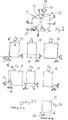
- FIG. 1 shows the application of a below mentioned as a "template” inventive device 10 for producing a joint from a grout 12.
- the device is thereby moved in the direction of the arrow 14 along a joint which extends in the plane of the drawing from left to right.
- the device 10 consists of a substantially cuboidal body, the edge facing the joint has a recess which extends parallel to the edge, and has an approximately semicircular inwardly directed cross section, which is reduced parallel to the joint against the direction of the arrow 14.
- Room diagonal through the body 18 of the device 10 is a channel 20, which opens into a rubber tube 22, which serves to receive the tip 24 of a conventional silicone or acrylic cartridge 26.
- FIG. 2 shows a more detailed representation of the device 10 according to the invention.
- the peel edge 28 is easy to see for simultaneous smoothing of the silicone joint. This is curved in the illustrated embodiment to the outside (on the joint to). It serves to shape the joint surface.
- the Figures 2.1 to 2.6 show the different views of the FIG. 2 shown device from all directions. a denotes the respective joint width in the plane and in height.
- the Figure 2.7 shows the section AA the Figure 2.1
- the Figure 2.8 shows the section BB of Figure 2.4 , In this illustration, the reduction in the depth of the recess 16 is clearly visible.
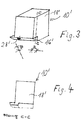
- FIGS. 3 and 4 show another embodiment of the present invention with a diagonal edge 28 '.
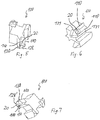
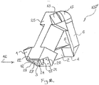
- FIGS. 5 to 10 show three-dimensional representations of another device according to the invention, which is in contrast to the above-described device also applicable to joints that are bounded by non-perpendicular surfaces, since the corresponding device rests only along a respective edge 110 on the surfaces bounding the joint. Furthermore, a clear demarcation of the joint is produced by the edges 110 and the scrapers 130 with a respective scraper edge 131 arranged next to the edges 110, namely outside the edges 110 in the direction of movement at the end of the device, can nevertheless remove joint material that has emerged laterally along the edges 110, so that with the preferred embodiment of the device according to the invention clean joints can be made even if the surfaces to be grouted are not exactly perpendicular to each other or have unevenness.
- the device is designed mirror-symmetrically about a space-diagonal surface, wherein the one room diagonal half has a straight joint termination with a straight edge 128, while the other half-space half a convexly curved conclusion for inwardly curved joints with a circular sector-shaped edge 128 'has.
- the feed opening 20 for the supply of the joint material also extends across the room by the device 100 according to the invention, so that by reversing the device on the silicone or acrylic syringe each of the opposite halves of the space diagonal mirror image device 100 are activated and either curved inwards or smooth joints can be made.
- the outer side of the edges 28, 128, 128 ', 11, 23 or / and the outer sides of the edges 110, 110', 7, 8, 21, 22 of the present invention may preferably be a thin, wettable one Sponge coated by the addition of a crawling of the grout around the edges and a setting of the grout on the outside of the edges can be prevented.
- This invention can be used in all fields where silicone, acrylic, adhesive is used, especially in the construction, metal, automotive industries.
- the system operation is very simple.
- the stencil is held on one side and a silicone syringe on the other.
- the silicone runs through the rubber tube and through the template into the conical opening in the lower part of the template.
- the template is moved in the desired direction.
- the template must be moved forward before the material exits, so the desired shape is retained.
- Stencils can be made of different shapes and different materials.
- the rubber hose turns around its own axis.
- the tapered portion of the template allows for easy movement of the material forward in the direction in which the template moves.
- Templates can move from right to left, from left to right, from bottom to top, and from top to bottom.
Description
Die vorliegende Erfindung betrifft eine Vorrichtung zur Herstellung von Fugen zwischen im Winkel aufeinander stoßenden Bauteilen durch Entlangführen der Vorrichtung an den beiden Bauteilen in einer Richtung.The present invention relates to a device for producing joints between angularly abutting components by passing the device on the two components in one direction.
Bisher mussten solche, als Dichtfugen weit verbreitete und in der Bautechnik übliche Fugen in einem zweistufigen Arbeitsprozess hergestellt werden. Zuerst wurde das Füllmaterial aus einer Kartusche oder einem anderen Behälter in die Fuge gespritzt und danach wurde die Fuge entweder mit einem Finger oder mit einer speziellen Schablone glattgezogen.So far, such joints, which are widely used as sealing joints and common in structural engineering, had to be produced in a two-stage working process. First, the filler was injected from a cartridge or other container into the joint and then the joint was smoothed with either a finger or a special template.
Aus der
Aufgabe der vorliegenden Erfindung ist es daher, die bekannte Vorrichtung dergestalt weiterzubilden, dass auch an unebenen und nicht rechtwinkligen Kanten eine saubere Fuge gezogen werden kann.Object of the present invention is therefore to develop the known device in such a way that even on uneven and non-rectangular edges a clean joint can be pulled.
Zur Lösung dieser Aufgabe umfassen die Widerlager zwei parallel zur Fuge verlaufende Kanten auf beiden Seiten der Fuge oder/und zwei unter einem Winkel, vorzugsweise orthogonal zur Fuge verlaufende Kanten auf beiden Seiten der Fuge. Bevorzugt sind sowohl die beiden parallel zur Fuge verlaufenden Kanten als auch die beiden unter einem Winkel zur Fuge verlaufenden Kanten vorgesehen. Die erstgenannten Kanten können vorteilhaft dafür ausgeführt sein, den in der Richtung vor dem Element angeordneten Raum zu begrenzen und damit die Fugenmasse im Wesentlichen in diesem Raum einzuschließen. Die zweitgenannten, unter einem Winkel zur Fuge verlaufenden Kanten können vorteilhaft dafür vorgesehen sein, als Abstreiferkante zu dienen, um aus dem Raum ausgetretenes Fugenmaterial zu entfernen, indem sie das Material von der Oberfläche des betreffenden Bauteils abstreifen.To solve this problem, the abutments comprise two edges running parallel to the joint on both sides of the joint and / or two edges running at an angle, preferably orthogonal to the joint, on both sides of the joint. Preferably, both the two edges running parallel to the joint and the two edges running at an angle to the joint are provided. The first-mentioned edges can be advantageously designed to limit the space arranged in the direction in front of the element and thus to enclose the grout substantially in this space. The second mentioned edges extending at an angle to the joint may advantageously be intended to serve as a scraper edge for removing grout material exiting the space by stripping the material from the surface of the component concerned.
Auf diese Weise lässt sich eine besonders saubere Fuge erzielen.In this way, a particularly clean joint can be achieved.
Besonders bevorzugt ist es dabei, dass der Raum einen diagonal angeschnittenen, runden, ovalen oder mehreckigen, beispielsweise quadratischen Querschnitt senkrecht zu der Richtung der Fuge aufweist.It is particularly preferred that the space has a diagonal, round, oval or polygonal, for example, square cross-section perpendicular to the direction of the joint.
Besonders bevorzugt ist es dabei, wenn der Raum zusätzlich dergestalt konisch ausgebildet ist, dass sein Durchmesser auf das Element hin abnimmt. Auf diese Weise wird durch die Vorwärtsbewegung im Verlaufe der Fugenrichtung die Fugenmasse zusätzlich in die Fuge gepresst und ein Austreten der Fugenmasse nach vorne verhindert.It is particularly preferred if the space is additionally conical in such a way that its diameter decreases towards the element. In this way, by the forward movement in the course of the joint direction, the grout additionally pressed into the joint and prevents leakage of grout forward.
Weiter ist es besonders bevorzugt, wenn die der Fuge zugewandte Kante des Elements gerade zwischen den Widerlagern verläuft. Damit können diagonal verlaufende Fugen erzeugt werden.Further, it is particularly preferred if the joint of the facing edge of the element runs just between the abutments. This allows diagonal joints to be created.
Zur Herstellung von gewölbten Fugen ist es bevorzugt, dass die der Fuge zugewandte Kante des Elements zur Fuge hin gewölbt konvex verläuft.For the production of arched joints, it is preferred that the edge of the element facing the joint runs convex towards the joint.
Die vorliegende Erfindung wird nun an Hand des in den beigefügten Zeichnungen dargestellten Ausführungsbeispiels näher erläutert. Es zeigt:
-
Figur 1 -
Figur 2 eine Detaildarstellung der Vorrichtung derFigur 1 - die
Figuren 2.1 bis 2.8 die verschiedenen Ansichten und Schnitte derFigur 2 ; -
Figur 3 eine weitere erfindungsgemäße Vorrichtung, bei der zusätzlich die Silikonreste entfernt werden können; -
Figur 4 den Schnitt C-C derFigur 3 ; -
Figuren 5 bis 10 eine weitere besonders bevorzugte erfindungsgemäße Vorrichtung, bei der die Widerlager zur Begrenzung der Fuge durch zwei parallel zur Fuge verlaufende Kanten auf beiden Seiten der Fuge gebildet sind; -
Figur 11 -
Figur 12Figur 11
-
FIG. 1 the use of a device according to the invention for pulling a joint; -
FIG. 2 a detailed representation of the device ofFIG. 1 ; - the
Figures 2.1 to 2.8 the different views and cuts of theFIG. 2 ; -
FIG. 3 a further device according to the invention, in which additionally the silicone residues can be removed; -
FIG. 4 the cut CC theFIG. 3 ; -
FIGS. 5 to 10 Another particularly preferred device according to the invention, in which the abutments are formed to limit the joint by two parallel to the joint extending edges on both sides of the joint; -
FIG. 11 a further device according to the invention, which can be produced particularly inexpensively by injection molding; -
FIG. 12 another perspective view of the device ofFIG. 11 from another direction.
Die Vorrichtung 10 besteht aus einem im wesentlichen quaderförmigen Körper, dessen der Fuge zugewandte Kante eine Ausnehmung aufweist, die parallel zu der Kante verläuft, und einen etwa halbkreisförmig nach innen gerichteten Querschnitt aufweist, der parallel zur Fuge entgegen der Richtung des Pfeils 14 verringert wird.The
Raumdiagonal durch den Körper 18 der Vorrichtung 10 verläuft ein Kanal 20, der in einen Gummischlauch 22 mündet, der zur Aufnahme der Spitze 24 einer üblichen Silikon- oder Acryl-Patrone 26 dient.Room diagonal through the
Wird nun Fugenmasse aus der Patrone 26 in üblicher Weise ausgepresst, so fließt diese in den Gummischlauch 22 und von dort durch den Kanal 20 in den kantenparallelen Hohlraum 16. An dessen Ende befindet sich eine Kante 28 (in den
Die
Die
Die
Um die erfindungsgemäße Vorrichtung 100' noch besser in Spritzgussverfahren herstellen zu können, ist die Ausführungsform gemäß
Die Ausführungsform gemäß den
-
Figur 11Fugenmasse 12. Die Vorrichtung wird dabei in Richtung desPfeils 16 entlang einer Fuge bewegt, die in der Zeichnungsebene von links unten nach rechts oben verläuft. - Die Vorrichtung umfasst einen Ausnehmungen oder Aussparungen
aufweisenden Körper 25, durch den raumdiagonal einKanal 15 verläuft, welcher zur Aufnahme derSpritze 18 einer üblichen Silikon- oder Acryl-Patrone oder dergleichen 19 dient, und in einen zur Fuge hin offenen, sich parallel zu diesererstreckenden Kanal 14 bzw. 20 mündet, welcher an einem Ende durch ein Element begrenzt ist, welches eine die Fuge formende Kante oder Begrenzungsfläche aufweist. DieserKanal 14 bzw. 20 gehört zu einem vor dem Element angeordneten, von demKörper 25 und den zu verfugenden Bauteilen umschlossenen Raum und wird wie bei der vorangehend beschriebenen Ausführungsform durch Widerlagerkanten begrenzt, die parallel zur Fuge verlaufen. - Wird nun
Fugenmasse 12 aus derPatrone 19 in üblicher Weise ausgepresst, so fließt diese in denKanal 15 und von dort in denKanal 14 bzw. 20 und damit in den kantenparallelen Hohlraum, an dessen Ende sich die angesprochene, in den Figuren mit 9 bzw. 24 bezeichnete Kante befindet, die die Oberfläche der entstehenden Fuge formt. - Unter Verwendung der in
Figuren 1112 eingetragenen Bezugszeichen kann die dargestellte Ausführungsform einer Vorrichtung 100' zur Herstellung von Fugen zwischen im Winkel aufeinander stoßenden Bauteilen durch Entlangführen der Vorrichtung an den Bauteilen in einerRichtung 16 und deren praktische Verwendung weiter wie folgt beschrieben werden. Durch denKanal 15 desKörpers 25 der Vorrichtung wird Fugenmasse zugeführt, die in den zur Fuge hinoffenen Kanal 14 bzw.Kanal 20 des Körpers und hierüber in den Bereich, in dem die Fuge herzustellen ist, austritt. - Der Körper wird so zwischen den Bauteilen positioniert, dass entweder der
Kanal 14 auf der einen Seite des Körpers oder derKanal 20 auf einer anderen Seite des Körpers dem Winkelbereich zwischen den Bauteilen zugewandt ist, je nachdem, welche Form die Fuge im Querschnitt haben soll. Bei dem Ausführungsbeispiel lässt sich die Fuge mit einer dreieckigen Form oder alternativ mit einer gewölbt konvex verlaufenden Form herstellen, wofür das die Fugenoberfläche definierende und glättende Teil entsprechend geformt ist,nämlich das Teil 11 bzw.das Teil 23 des Körpers. - Wird nun Fugenmasse
über den Kanal 15 undden Kanal 14 bzw. 20 zugeführt und gleichzeitig der Körper 25 in der Richtung des Pfeils 16 bewegt, so wird mit Hilfe des Teils 26 bzw. 27 die außerhalb des Sollbereichs für die Fugenmasse liegende Fugenmasse mitgenommen und ggf. verteilt und in den Sollbereich für die Fugenmasse gedrückt. Das Teil 9 bzw. 24 am Ende desKanals 14 bzw. 20 gibt der Fuge die richtige Form. Dabei wird die Fuge mit Hilfe des Teils 11 bzw. 23 geglättet, wobei dessenKante 17 bzw. 3 die Oberfläche der entstehenden Fuge definiert und die richtige Form verleiht, beim Ausführungsbeispiel geradlinig zwischen den Widerlagern für einen dreieckigen Fugenquerschnitt oder zur Fuge hin gewölbt konvex für einen entsprechenden Fugenquerschnitt. Die Bezugszeichen den Kanal 14 bzw. 20 umfassender Raum, um ein seitliches Auslaufen der Fugenmasse zu verhindern. Sollte trotzdem Fugenmasse auslaufen, so wird überflüssige Fugenmasse durch ebenfalls eine Widerlagerfunktion und zusätzlich eine Abstreiferfunktion erfüllende Elemente 6, 13, 1 und 2 entfernt, welche vorzugsweise zumindest teilweise mit Abstreiferkanten ausgeführt sind.
-
FIG. 11 shows the application of a device according to the invention 100 'for producing a joint from agrout 12. The device is thereby moved in the direction of thearrow 16 along a joint which extends in the drawing plane from bottom left to top right. - The device comprises a recesses or
recesses having body 25, through which achannel 15 extends diagonally across the space, which serves to receive thesyringe 18 of a conventional silicone or acrylic cartridge or the like 19, and in an open towards the joint, parallel to this extendingchannel channel body 25 and the components to be joined and, as in the previously described embodiment, is limited by abutment edges which run parallel to the joint. - If now
grout 12 pressed out of thecartridge 19 in a conventional manner, it flows into thechannel 15 and from there into thechannel - Using the in
Figures 11 and12 As shown, the illustrated embodiment of a device 100 'for making joints between angularly abutting components by passing the device along the components in onedirection 16 and their practical use can be further described as follows. Through thechannel 15 of thebody 25 of the device grout is supplied, which exits in the open towards thejoint channel 14 andchannel 20 of the body and here in the area in which the joint is to be produced, emerges. - The body is positioned between the components such that either the
channel 14 on one side of the body or thechannel 20 on another side of the body faces the angular region between the components, depending on which shape the groove is to have in cross-section. In the embodiment, the joint can be made with a triangular shape or alternatively with a curved convex shape, for which the joint surface defining and smoothing part is shaped accordingly, namely thepart 11 and thepart 23 of the body. - Now, if joint compound is supplied via the
channel 15 and thechannel body 25 is moved in the direction of thearrow 16, so with the help of thepart part 9 or 24 at the end of thechannel part edge 17 or 3 defines the surface of the resulting joint and gives the correct shape, in the embodiment straight convex between the abutments for a triangular joint cross-section or to the joint convex for a corresponding joint cross-section. - The
reference numerals channel fulfilling elements
Schließlich können die von der Fuge aus betrachtet äußere Seite der Kanten 28, 128, 128', 11, 23 oder/und die äußeren Seiten der Kanten 110, 110', 7, 8, 21, 22 der vorliegenden Erfindung vorzugsweise mit einem dünnen anfeuchtbaren Schwamm beschichtet sein, durch den zusätzlich ein Herumkriechen der Fugenmasse um die Kanten und ein Festsetzen der Fugenmasse auf der Außenseite der Kanten verhindert werden kann.Finally, the outer side of the
Diese Erfindung kann in allen Bereichen eingesetzt werden, wo Silikon, Acryl, Klebstoff verwendet wird, vor allem in der Bau-, Metall-, Autoindustrie.This invention can be used in all fields where silicone, acrylic, adhesive is used, especially in the construction, metal, automotive industries.
Jetzt aktuell verwendete Schablonen haben eine Menge Mängel:
- Einen großen Verlust von Material,
- Verschwendung von Zeit,
- Umweltverschmutzung,
- ungleichmäßige Dicke der Fugen,
- nur professionelle Mitarbeiter können mit diesen Schablonen arbeiten.
- A big loss of material,
- Waste of time,
- Environmental pollution,
- uneven thickness of the joints,
- only professional employees can work with these templates.
Mit dieser Erfindung wird gelöst:
- Materialausnutzung 99 %,
- Hochgeschwindigkeit der Arbeiten,
- es kann von Amateuren und Profis verwendet werden,
- die Fugen sind gerade und gleich dick,
- große Einsparung der Materialien,
- Umweltschutz.
- Die Schablone ist sehr klein,
Minimum 10 mm x 10 mm x 10 mm, - Verschiedene Länge des Gummischlauchs, kommt leicht an unzugängliche Stellen,
- eine Schablone für alle Richtungen.
- Material utilization 99%,
- High speed of work,
- it can be used by amateurs and professionals,
- the joints are straight and the same thickness,
- great savings of materials,
- Environmental Protection.
- The template is very small, minimum 10 mm x 10 mm x 10 mm,
- Different length of rubber hose, easily comes to inaccessible places,
- a template for all directions.
Die Systembedienung ist sehr einfach. Auf der einen Seite wird die Schablone gehalten und auf der anderen eine Silikonspritze. Das Silikon läuft durch den Gummischlauch und durch die Schablone in die konische Öffnung im unteren Bereich der Schablone.The system operation is very simple. The stencil is held on one side and a silicone syringe on the other. The silicone runs through the rubber tube and through the template into the conical opening in the lower part of the template.
Wenn zu sehen ist, dass das Silikon die konische Öffnung ausgefüllt hat, wird die Schablone in die gewünschte Richtung bewegt.If it is seen that the silicone has filled the conical opening, the template is moved in the desired direction.
Die Schablone muss nach vorne bewegt werden, bevor das Material austritt, so bleibt die gewünschte Form erhalten.The template must be moved forward before the material exits, so the desired shape is retained.
Im Fall, dass das Material austritt, kann es mit der Schablone entfernt werden.In case the material comes out, it can be removed with the template.
Schablonen können aus verschiedenen Formen und verschiedenen Materialien sein.Stencils can be made of different shapes and different materials.
Der Gummischlauch dreht sich um die eigene Achse.The rubber hose turns around its own axis.
Der konische Abschnitt der Schablone ermöglicht die leichte Bewegung des Materials nach vorne in die Richtung, in die sich die Schablone bewegt.The tapered portion of the template allows for easy movement of the material forward in the direction in which the template moves.
Schablonen können sich von rechts nach links, von links nach rechts, von unten nach oben, und von oben nach unten bewegen.Templates can move from right to left, from left to right, from bottom to top, and from top to bottom.
Claims (7)
- Device (10; 10'; 100; 100') for making joints between components abutting each other in an angle by guiding the device along the components in a direction (14), with a body (18; 18', 118; 25) which comprises an element wherein the element an edge (28; 128; 128', 11; 23) facing the joint for shaping the joint, which is surrounded on both sides by abutments each abutting on one of the components, and comprises a channel (20) leading into a space (16) which is arranged, in the direction (14), before the element, and is enclosed by the body (18; 18'; 118; 25) and the components, and the other end (22) thereof is formed for receiving a connecting device of a container (26) with joint sealant,
characterized in that the abutments consist of two edges (110) extending in parallel to the joint on both sides of the joint, and two edges (131) extending in an angle, preferably orthogonal to the joint, on both sides of the joint. - Device (10) according to claim 1, characterized in that the space (16) comprises, perpendicular to the direction (14), a diagonally cutted, round, oval or polygonal, for example square, cross section.
- Device (10) according to claim 2, characterized in that the space (16) is additionally conically formed in such a way that a diameter thereof is reduced toward the element.
- Device (10) according to one of claims 1 to 3, characterized in that the edge (28) of the element facing the joint extends straight between the abutments.
- Device (10) according to one of claims 1 to 4, characterized in that the edge (28) of the element facing the joint extends toward the joint as a convex arch.
- Device according to one of claims 1 to 5, characterized in that the body (25) is elastically deformable in such a way that the abutments can be adapted to an angle between the abutting components differing from a standard angle.
- Device according to one of claims 1 to 6, characterized by at least one wettable sponge element on an outer side of the body adjacent to the abutment edge or abutment surface.
Applications Claiming Priority (1)
| Application Number | Priority Date | Filing Date | Title |
|---|---|---|---|
| DE202014003184.3U DE202014003184U1 (en) | 2014-04-14 | 2014-04-14 | Device for producing joints between components which abut one another at an angle |
Publications (2)
| Publication Number | Publication Date |
|---|---|
| EP2942109A1 EP2942109A1 (en) | 2015-11-11 |
| EP2942109B1 true EP2942109B1 (en) | 2019-12-11 |
Family
ID=52009305
Family Applications (1)
| Application Number | Title | Priority Date | Filing Date |
|---|---|---|---|
| EP15163528.1A Active EP2942109B1 (en) | 2014-04-14 | 2015-04-14 | Device for creating joints between angled components |
Country Status (2)
| Country | Link |
|---|---|
| EP (1) | EP2942109B1 (en) |
| DE (1) | DE202014003184U1 (en) |
Families Citing this family (4)
| Publication number | Priority date | Publication date | Assignee | Title |
|---|---|---|---|---|
| JP7152930B2 (en) * | 2018-10-11 | 2022-10-13 | 株式会社Subaru | Sealing material dispensing nozzle and sealing material dispensing device |
| JP7152928B2 (en) * | 2018-10-11 | 2022-10-13 | 株式会社Subaru | Sealing material dispensing nozzle and sealing material dispensing device |
| JP7152929B2 (en) * | 2018-10-11 | 2022-10-13 | 株式会社Subaru | Sealing material dispensing nozzle and sealing material dispensing device |
| DE102021000704B4 (en) * | 2021-02-11 | 2023-09-14 | Bernd Kowalewski | Application nozzle with an elastic molding area for manually applying a dimensioned pasty sealant strand for corner joint sealing |
Family Cites Families (5)
| Publication number | Priority date | Publication date | Assignee | Title |
|---|---|---|---|---|
| US3559234A (en) * | 1969-01-08 | 1971-02-02 | Dow Corning | Corner tool and applicator nozzle |
| DE7812552U1 (en) * | 1978-04-19 | 1978-09-14 | Zern Klaus | Device for introducing and applying various materials from cartridges or the like |
| US5622728A (en) * | 1993-09-08 | 1997-04-22 | Thomas P. Mahoney | Wiping device for caulking, and method of forming same |
| EP1522654A3 (en) * | 2003-10-08 | 2007-05-23 | Christian Hoffmann | Tool for filling joints |
| DE202013003380U1 (en) * | 2013-04-11 | 2013-05-31 | Hasan Balci | Spout for plastic grout |
-
2014
- 2014-04-14 DE DE202014003184.3U patent/DE202014003184U1/en not_active Expired - Lifetime
-
2015
- 2015-04-14 EP EP15163528.1A patent/EP2942109B1/en active Active
Non-Patent Citations (1)
| Title |
|---|
| None * |
Also Published As
| Publication number | Publication date |
|---|---|
| EP2942109A1 (en) | 2015-11-11 |
| DE202014003184U1 (en) | 2014-11-05 |
Similar Documents
| Publication | Publication Date | Title |
|---|---|---|
| EP2942109B1 (en) | Device for creating joints between angled components | |
| DE2426322A1 (en) | SPATULA | |
| EP3255222B1 (en) | Device and system for processing a jointing material | |
| DE202014001032U1 (en) | Nozzle for applying pasty substances | |
| EP0711887A1 (en) | Tool for finishing joint with permanently elastic sealant | |
| DE2348607C2 (en) | Thermal welding process for connecting two plastic walls to the front | |
| DE202013003380U1 (en) | Spout for plastic grout | |
| EP1666683B1 (en) | Tool for finishing and smoothing permanently elastic sealant joints | |
| EP2363564B1 (en) | Glue nozzle for use in the gluing of a disc assembly with a profile for windows and doors | |
| DE102018122840A1 (en) | Device for processing adhesives and sealants | |
| DE202005019332U1 (en) | Sealing profile used in e.g. car window, door, has weak sections distributed in 180-degree area, while remaining sections and outer side of sealing profile are provided with reinforcements | |
| DE102010045992A1 (en) | Grouting tool for filling joint between glass pane and window frame, has plate with short edge that is connected in perpendicular to long edges such that trough is extended from short edge to curvature which connects long edges | |
| DE202021105473U1 (en) | Nozzle, nozzle arrangement and device for introducing a pasty medium into a miter joint | |
| DE202022106552U1 (en) | Tool for finishing and smoothing joints | |
| DE102021000704B4 (en) | Application nozzle with an elastic molding area for manually applying a dimensioned pasty sealant strand for corner joint sealing | |
| DE2940582C2 (en) | Method and device for coating elements for sorting, classifying and / or separating goods | |
| DE102021103767A1 (en) | Joint drawing attachment, joint cartridge and method therefor | |
| DE10351388B4 (en) | Tool for working grout, used to seal joints between tiles and the like, has a choice of cutting edges in its elastic material with holders to fit guides according to the joint configuration | |
| DE202022106549U1 (en) | Tool for finishing and smoothing joints | |
| DE19851657C2 (en) | Device for post-treating grout | |
| DE6939916U (en) | DEVICE FOR PRESSING HOSE COUPLINGS AND THE LIKE. ON HOSE. | |
| DE202015104983U1 (en) | joint filler | |
| EP3891353A1 (en) | Method and device for producing thermoplastic spacers | |
| DE202008012507U1 (en) | Device for introducing filler in joints | |
| DE2000687C (en) | Device for applying a flowable mass |
Legal Events
| Date | Code | Title | Description |
|---|---|---|---|
| PUAI | Public reference made under article 153(3) epc to a published international application that has entered the european phase |
Free format text: ORIGINAL CODE: 0009012 |
|
| AK | Designated contracting states |
Kind code of ref document: A1 Designated state(s): AL AT BE BG CH CY CZ DE DK EE ES FI FR GB GR HR HU IE IS IT LI LT LU LV MC MK MT NL NO PL PT RO RS SE SI SK SM TR |
|
| AX | Request for extension of the european patent |
Extension state: BA ME |
|
| 17P | Request for examination filed |
Effective date: 20160504 |
|
| RBV | Designated contracting states (corrected) |
Designated state(s): AL AT BE BG CH CY CZ DE DK EE ES FI FR GB GR HR HU IE IS IT LI LT LU LV MC MK MT NL NO PL PT RO RS SE SI SK SM TR |
|
| GRAP | Despatch of communication of intention to grant a patent |
Free format text: ORIGINAL CODE: EPIDOSNIGR1 |
|
| STAA | Information on the status of an ep patent application or granted ep patent |
Free format text: STATUS: GRANT OF PATENT IS INTENDED |
|
| RIC1 | Information provided on ipc code assigned before grant |
Ipc: B05C 17/005 20060101AFI20190503BHEP Ipc: B05C 17/10 20060101ALN20190503BHEP |
|
| INTG | Intention to grant announced |
Effective date: 20190529 |
|
| GRAS | Grant fee paid |
Free format text: ORIGINAL CODE: EPIDOSNIGR3 |
|
| GRAA | (expected) grant |
Free format text: ORIGINAL CODE: 0009210 |
|
| STAA | Information on the status of an ep patent application or granted ep patent |
Free format text: STATUS: THE PATENT HAS BEEN GRANTED |
|
| AK | Designated contracting states |
Kind code of ref document: B1 Designated state(s): AL AT BE BG CH CY CZ DE DK EE ES FI FR GB GR HR HU IE IS IT LI LT LU LV MC MK MT NL NO PL PT RO RS SE SI SK SM TR |
|
| REG | Reference to a national code |
Ref country code: GB Ref legal event code: FG4D Free format text: NOT ENGLISH |
|
| REG | Reference to a national code |
Ref country code: CH Ref legal event code: EP |
|
| REG | Reference to a national code |
Ref country code: AT Ref legal event code: REF Ref document number: 1211672 Country of ref document: AT Kind code of ref document: T Effective date: 20191215 |
|
| REG | Reference to a national code |
Ref country code: DE Ref legal event code: R096 Ref document number: 502015011172 Country of ref document: DE |
|
| REG | Reference to a national code |
Ref country code: IE Ref legal event code: FG4D Free format text: LANGUAGE OF EP DOCUMENT: GERMAN |
|
| REG | Reference to a national code |
Ref country code: NL Ref legal event code: MP Effective date: 20191211 |
|
| REG | Reference to a national code |
Ref country code: LT Ref legal event code: MG4D |
|
| PG25 | Lapsed in a contracting state [announced via postgrant information from national office to epo] |
Ref country code: LV Free format text: LAPSE BECAUSE OF FAILURE TO SUBMIT A TRANSLATION OF THE DESCRIPTION OR TO PAY THE FEE WITHIN THE PRESCRIBED TIME-LIMIT Effective date: 20191211 Ref country code: SE Free format text: LAPSE BECAUSE OF FAILURE TO SUBMIT A TRANSLATION OF THE DESCRIPTION OR TO PAY THE FEE WITHIN THE PRESCRIBED TIME-LIMIT Effective date: 20191211 Ref country code: NO Free format text: LAPSE BECAUSE OF FAILURE TO SUBMIT A TRANSLATION OF THE DESCRIPTION OR TO PAY THE FEE WITHIN THE PRESCRIBED TIME-LIMIT Effective date: 20200311 Ref country code: GR Free format text: LAPSE BECAUSE OF FAILURE TO SUBMIT A TRANSLATION OF THE DESCRIPTION OR TO PAY THE FEE WITHIN THE PRESCRIBED TIME-LIMIT Effective date: 20200312 Ref country code: LT Free format text: LAPSE BECAUSE OF FAILURE TO SUBMIT A TRANSLATION OF THE DESCRIPTION OR TO PAY THE FEE WITHIN THE PRESCRIBED TIME-LIMIT Effective date: 20191211 Ref country code: BG Free format text: LAPSE BECAUSE OF FAILURE TO SUBMIT A TRANSLATION OF THE DESCRIPTION OR TO PAY THE FEE WITHIN THE PRESCRIBED TIME-LIMIT Effective date: 20200311 Ref country code: FI Free format text: LAPSE BECAUSE OF FAILURE TO SUBMIT A TRANSLATION OF THE DESCRIPTION OR TO PAY THE FEE WITHIN THE PRESCRIBED TIME-LIMIT Effective date: 20191211 |
|
| PG25 | Lapsed in a contracting state [announced via postgrant information from national office to epo] |
Ref country code: RS Free format text: LAPSE BECAUSE OF FAILURE TO SUBMIT A TRANSLATION OF THE DESCRIPTION OR TO PAY THE FEE WITHIN THE PRESCRIBED TIME-LIMIT Effective date: 20191211 Ref country code: HR Free format text: LAPSE BECAUSE OF FAILURE TO SUBMIT A TRANSLATION OF THE DESCRIPTION OR TO PAY THE FEE WITHIN THE PRESCRIBED TIME-LIMIT Effective date: 20191211 |
|
| PG25 | Lapsed in a contracting state [announced via postgrant information from national office to epo] |
Ref country code: AL Free format text: LAPSE BECAUSE OF FAILURE TO SUBMIT A TRANSLATION OF THE DESCRIPTION OR TO PAY THE FEE WITHIN THE PRESCRIBED TIME-LIMIT Effective date: 20191211 |
|
| PG25 | Lapsed in a contracting state [announced via postgrant information from national office to epo] |
Ref country code: PT Free format text: LAPSE BECAUSE OF FAILURE TO SUBMIT A TRANSLATION OF THE DESCRIPTION OR TO PAY THE FEE WITHIN THE PRESCRIBED TIME-LIMIT Effective date: 20200506 Ref country code: EE Free format text: LAPSE BECAUSE OF FAILURE TO SUBMIT A TRANSLATION OF THE DESCRIPTION OR TO PAY THE FEE WITHIN THE PRESCRIBED TIME-LIMIT Effective date: 20191211 Ref country code: RO Free format text: LAPSE BECAUSE OF FAILURE TO SUBMIT A TRANSLATION OF THE DESCRIPTION OR TO PAY THE FEE WITHIN THE PRESCRIBED TIME-LIMIT Effective date: 20191211 Ref country code: CZ Free format text: LAPSE BECAUSE OF FAILURE TO SUBMIT A TRANSLATION OF THE DESCRIPTION OR TO PAY THE FEE WITHIN THE PRESCRIBED TIME-LIMIT Effective date: 20191211 Ref country code: NL Free format text: LAPSE BECAUSE OF FAILURE TO SUBMIT A TRANSLATION OF THE DESCRIPTION OR TO PAY THE FEE WITHIN THE PRESCRIBED TIME-LIMIT Effective date: 20191211 Ref country code: ES Free format text: LAPSE BECAUSE OF FAILURE TO SUBMIT A TRANSLATION OF THE DESCRIPTION OR TO PAY THE FEE WITHIN THE PRESCRIBED TIME-LIMIT Effective date: 20191211 |
|
| PG25 | Lapsed in a contracting state [announced via postgrant information from national office to epo] |
Ref country code: SM Free format text: LAPSE BECAUSE OF FAILURE TO SUBMIT A TRANSLATION OF THE DESCRIPTION OR TO PAY THE FEE WITHIN THE PRESCRIBED TIME-LIMIT Effective date: 20191211 Ref country code: SK Free format text: LAPSE BECAUSE OF FAILURE TO SUBMIT A TRANSLATION OF THE DESCRIPTION OR TO PAY THE FEE WITHIN THE PRESCRIBED TIME-LIMIT Effective date: 20191211 Ref country code: IS Free format text: LAPSE BECAUSE OF FAILURE TO SUBMIT A TRANSLATION OF THE DESCRIPTION OR TO PAY THE FEE WITHIN THE PRESCRIBED TIME-LIMIT Effective date: 20200411 |
|
| REG | Reference to a national code |
Ref country code: DE Ref legal event code: R097 Ref document number: 502015011172 Country of ref document: DE |
|
| PLBE | No opposition filed within time limit |
Free format text: ORIGINAL CODE: 0009261 |
|
| STAA | Information on the status of an ep patent application or granted ep patent |
Free format text: STATUS: NO OPPOSITION FILED WITHIN TIME LIMIT |
|
| PG25 | Lapsed in a contracting state [announced via postgrant information from national office to epo] |
Ref country code: DK Free format text: LAPSE BECAUSE OF FAILURE TO SUBMIT A TRANSLATION OF THE DESCRIPTION OR TO PAY THE FEE WITHIN THE PRESCRIBED TIME-LIMIT Effective date: 20191211 |
|
| 26N | No opposition filed |
Effective date: 20200914 |
|
| PG25 | Lapsed in a contracting state [announced via postgrant information from national office to epo] |
Ref country code: SI Free format text: LAPSE BECAUSE OF FAILURE TO SUBMIT A TRANSLATION OF THE DESCRIPTION OR TO PAY THE FEE WITHIN THE PRESCRIBED TIME-LIMIT Effective date: 20191211 Ref country code: MC Free format text: LAPSE BECAUSE OF FAILURE TO SUBMIT A TRANSLATION OF THE DESCRIPTION OR TO PAY THE FEE WITHIN THE PRESCRIBED TIME-LIMIT Effective date: 20191211 |
|
| REG | Reference to a national code |
Ref country code: CH Ref legal event code: PL |
|
| PG25 | Lapsed in a contracting state [announced via postgrant information from national office to epo] |
Ref country code: FR Free format text: LAPSE BECAUSE OF NON-PAYMENT OF DUE FEES Effective date: 20200430 Ref country code: LU Free format text: LAPSE BECAUSE OF NON-PAYMENT OF DUE FEES Effective date: 20200414 Ref country code: IT Free format text: LAPSE BECAUSE OF FAILURE TO SUBMIT A TRANSLATION OF THE DESCRIPTION OR TO PAY THE FEE WITHIN THE PRESCRIBED TIME-LIMIT Effective date: 20191211 Ref country code: LI Free format text: LAPSE BECAUSE OF NON-PAYMENT OF DUE FEES Effective date: 20200430 Ref country code: CH Free format text: LAPSE BECAUSE OF NON-PAYMENT OF DUE FEES Effective date: 20200430 |
|
| REG | Reference to a national code |
Ref country code: BE Ref legal event code: MM Effective date: 20200430 |
|
| PG25 | Lapsed in a contracting state [announced via postgrant information from national office to epo] |
Ref country code: PL Free format text: LAPSE BECAUSE OF FAILURE TO SUBMIT A TRANSLATION OF THE DESCRIPTION OR TO PAY THE FEE WITHIN THE PRESCRIBED TIME-LIMIT Effective date: 20191211 Ref country code: BE Free format text: LAPSE BECAUSE OF NON-PAYMENT OF DUE FEES Effective date: 20200430 |
|
| GBPC | Gb: european patent ceased through non-payment of renewal fee |
Effective date: 20200414 |
|
| PG25 | Lapsed in a contracting state [announced via postgrant information from national office to epo] |
Ref country code: IE Free format text: LAPSE BECAUSE OF NON-PAYMENT OF DUE FEES Effective date: 20200414 Ref country code: GB Free format text: LAPSE BECAUSE OF NON-PAYMENT OF DUE FEES Effective date: 20200414 |
|
| REG | Reference to a national code |
Ref country code: AT Ref legal event code: MM01 Ref document number: 1211672 Country of ref document: AT Kind code of ref document: T Effective date: 20200414 |
|
| PG25 | Lapsed in a contracting state [announced via postgrant information from national office to epo] |
Ref country code: AT Free format text: LAPSE BECAUSE OF NON-PAYMENT OF DUE FEES Effective date: 20200414 |
|
| PG25 | Lapsed in a contracting state [announced via postgrant information from national office to epo] |
Ref country code: TR Free format text: LAPSE BECAUSE OF FAILURE TO SUBMIT A TRANSLATION OF THE DESCRIPTION OR TO PAY THE FEE WITHIN THE PRESCRIBED TIME-LIMIT Effective date: 20191211 Ref country code: MT Free format text: LAPSE BECAUSE OF FAILURE TO SUBMIT A TRANSLATION OF THE DESCRIPTION OR TO PAY THE FEE WITHIN THE PRESCRIBED TIME-LIMIT Effective date: 20191211 Ref country code: CY Free format text: LAPSE BECAUSE OF FAILURE TO SUBMIT A TRANSLATION OF THE DESCRIPTION OR TO PAY THE FEE WITHIN THE PRESCRIBED TIME-LIMIT Effective date: 20191211 |
|
| PG25 | Lapsed in a contracting state [announced via postgrant information from national office to epo] |
Ref country code: MK Free format text: LAPSE BECAUSE OF FAILURE TO SUBMIT A TRANSLATION OF THE DESCRIPTION OR TO PAY THE FEE WITHIN THE PRESCRIBED TIME-LIMIT Effective date: 20191211 |
|
| PGFP | Annual fee paid to national office [announced via postgrant information from national office to epo] |
Ref country code: DE Payment date: 20220426 Year of fee payment: 8 |
|
| REG | Reference to a national code |
Ref country code: DE Ref legal event code: R119 Ref document number: 502015011172 Country of ref document: DE |
|
| PG25 | Lapsed in a contracting state [announced via postgrant information from national office to epo] |
Ref country code: DE Free format text: LAPSE BECAUSE OF NON-PAYMENT OF DUE FEES Effective date: 20231103 |