EP2941990B1 - Bodenpflegegerät - Google Patents
Bodenpflegegerät Download PDFInfo
- Publication number
- EP2941990B1 EP2941990B1 EP15166362.2A EP15166362A EP2941990B1 EP 2941990 B1 EP2941990 B1 EP 2941990B1 EP 15166362 A EP15166362 A EP 15166362A EP 2941990 B1 EP2941990 B1 EP 2941990B1
- Authority
- EP
- European Patent Office
- Prior art keywords
- air
- channel
- suction fan
- connecting element
- exhaust air
- Prior art date
- Legal status (The legal status is an assumption and is not a legal conclusion. Google has not performed a legal analysis and makes no representation as to the accuracy of the status listed.)
- Active
Links
Images

Classifications
-
- A—HUMAN NECESSITIES
- A47—FURNITURE; DOMESTIC ARTICLES OR APPLIANCES; COFFEE MILLS; SPICE MILLS; SUCTION CLEANERS IN GENERAL
- A47L—DOMESTIC WASHING OR CLEANING; SUCTION CLEANERS IN GENERAL
- A47L9/00—Details or accessories of suction cleaners, e.g. mechanical means for controlling the suction or for effecting pulsating action; Storing devices specially adapted to suction cleaners or parts thereof; Carrying-vehicles specially adapted for suction cleaners
- A47L9/02—Nozzles
- A47L9/04—Nozzles with driven brushes or agitators
- A47L9/0405—Driving means for the brushes or agitators
- A47L9/0411—Driving means for the brushes or agitators driven by electric motor
-
- A—HUMAN NECESSITIES
- A47—FURNITURE; DOMESTIC ARTICLES OR APPLIANCES; COFFEE MILLS; SPICE MILLS; SUCTION CLEANERS IN GENERAL
- A47L—DOMESTIC WASHING OR CLEANING; SUCTION CLEANERS IN GENERAL
- A47L5/00—Structural features of suction cleaners
- A47L5/12—Structural features of suction cleaners with power-driven air-pumps or air-compressors, e.g. driven by motor vehicle engine vacuum
- A47L5/22—Structural features of suction cleaners with power-driven air-pumps or air-compressors, e.g. driven by motor vehicle engine vacuum with rotary fans
- A47L5/28—Suction cleaners with handles and nozzles fixed on the casings, e.g. wheeled suction cleaners with steering handle
- A47L5/30—Suction cleaners with handles and nozzles fixed on the casings, e.g. wheeled suction cleaners with steering handle with driven dust-loosening tools, e.g. rotating brushes
-
- A—HUMAN NECESSITIES
- A47—FURNITURE; DOMESTIC ARTICLES OR APPLIANCES; COFFEE MILLS; SPICE MILLS; SUCTION CLEANERS IN GENERAL
- A47L—DOMESTIC WASHING OR CLEANING; SUCTION CLEANERS IN GENERAL
- A47L9/00—Details or accessories of suction cleaners, e.g. mechanical means for controlling the suction or for effecting pulsating action; Storing devices specially adapted to suction cleaners or parts thereof; Carrying-vehicles specially adapted for suction cleaners
- A47L9/02—Nozzles
- A47L9/04—Nozzles with driven brushes or agitators
- A47L9/0461—Dust-loosening tools, e.g. agitators, brushes
- A47L9/0466—Rotating tools
- A47L9/0477—Rolls
-
- A—HUMAN NECESSITIES
- A47—FURNITURE; DOMESTIC ARTICLES OR APPLIANCES; COFFEE MILLS; SPICE MILLS; SUCTION CLEANERS IN GENERAL
- A47L—DOMESTIC WASHING OR CLEANING; SUCTION CLEANERS IN GENERAL
- A47L9/00—Details or accessories of suction cleaners, e.g. mechanical means for controlling the suction or for effecting pulsating action; Storing devices specially adapted to suction cleaners or parts thereof; Carrying-vehicles specially adapted for suction cleaners
- A47L9/10—Filters; Dust separators; Dust removal; Automatic exchange of filters
- A47L9/12—Dry filters
-
- A—HUMAN NECESSITIES
- A47—FURNITURE; DOMESTIC ARTICLES OR APPLIANCES; COFFEE MILLS; SPICE MILLS; SUCTION CLEANERS IN GENERAL
- A47L—DOMESTIC WASHING OR CLEANING; SUCTION CLEANERS IN GENERAL
- A47L9/00—Details or accessories of suction cleaners, e.g. mechanical means for controlling the suction or for effecting pulsating action; Storing devices specially adapted to suction cleaners or parts thereof; Carrying-vehicles specially adapted for suction cleaners
- A47L9/10—Filters; Dust separators; Dust removal; Automatic exchange of filters
- A47L9/12—Dry filters
- A47L9/122—Dry filters flat
-
- A—HUMAN NECESSITIES
- A47—FURNITURE; DOMESTIC ARTICLES OR APPLIANCES; COFFEE MILLS; SPICE MILLS; SUCTION CLEANERS IN GENERAL
- A47L—DOMESTIC WASHING OR CLEANING; SUCTION CLEANERS IN GENERAL
- A47L9/00—Details or accessories of suction cleaners, e.g. mechanical means for controlling the suction or for effecting pulsating action; Storing devices specially adapted to suction cleaners or parts thereof; Carrying-vehicles specially adapted for suction cleaners
- A47L9/32—Handles
- A47L9/325—Handles for wheeled suction cleaners with steering handle
Definitions
- the invention relates to a floor care device in the form of a carpet cleaning device as Bürststaubsauger with a bottom facing Bürstvorsatz for receiving a driven brush roller, wherein the brush attachment is connected via a pivotable connecting element with air ducts as a connecting piece for an attachable filter housing with a handle as a handle on corresponding connections and the brush attachment receives at least one electric motor for a suction fan and for driving the brush roller and the air ducts of the pivotable connecting element for feeding the dirt laden suction air from the brush attachment to the filter housing and the air return of the filtered air through a parallel air duct to the brush attachment and are guided an exhaust air from the suction fan via exhaust openings takes place.
- the DE 91 04 750 U1 discloses a brush vacuum cleaner with a pivotable connection between a filter housing and a brush attachment.
- the suction fan is arranged in the brush attachment.
- the object of the invention is to allow for generic floor care devices in a simple way, the arrangement of a relatively large filter element without increasing the height of the brush attachment incorporating the existing equipment parts and to ensure easy accessibility to the filter element.
- the pivotable connecting element has an additional third air duct as the exhaust duct of the suction fan in the brush attachment with a supply to a blow-out in the filter housing with an air outlet and an intermediate filter.
- an inflow to the third air duct runs as an exhaust duct for exhaust air of the suction fan frontally to a suction fan associated connection element side contact surface, which is provided with at least one corresponding opening.
- the intake fan-side inflow to the third air duct takes place along a pivot axis of the connecting element, whereby an inflow is ensured with appropriate design of the at least one opening in each pivot position.
- the preferred inflow to the third air duct as exhaust duct for Exhaust air of the suction fan through a jacket-shaped arranged around the fan housing channel and corresponding openings in the inflow side of the suction fan associated contact surface with sealing and by a subsequent chamber in the pivotable connecting element extends, which is sealed to the air return passage.
- other front-side inflows are conceivable, for example by means of a separate from the blower housing channel, which opens into an opening of the contact surface.
- openings in the inlet side of the suction fan associated bearing surface are arranged with sealing ring and correspond with a concentric with seal around the air return passage chamber disposed in the pivotable connecting element as an inflow to the exhaust duct.
- the exhaust duct as an additional rectangular channel laterally delimits the two further air ducts with a circular cross-section.
- blow-out region of the filter housing is designed as a filter chamber for receiving a removable particulate filter and the air outlet has a screen cover.
- the illustrated Bürststaubsauger consists of a brush attachment 1 and an attachable filter housing 2 with a handle, wherein the brush attachment 1 has a motor 3 for a suction fan 4 and a brush roller, not shown.
- the air ducts 6, 7 and 8 are connected in accordance with associated, further channels in the filter housing 2 by the connection of the connecting element 5 and continued independently of the pivoting movement of the connecting element 5.
- the air duct 6 is used in a known manner for supplying the dirt laden with suction air from the brush attachment 1 to the filter housing 2, and there is an air return of the filtered air through the air duct 7 to the brush attachment. 1
- a third air duct as the exhaust duct 8 of the pivotable connecting element 5 is arranged for the exhaust air of the suction fan 4.
- the inflow to the third air duct as the exhaust duct 8 for the exhaust air of the suction fan 4 is carried out at the front end to a suction fan 4 associated connection element side contact surface, which is provided with at least one corresponding opening 10.
- the frontal inflow takes place by a jacket-shaped, arranged around the blower housing channel 9 and corresponding openings 10 in the inflow surface of the suction fan 4 associated contact surface and an upstream of the air duct 8 chamber 11 in the pivotable connecting element 5 with associated seals.
- the exhaust duct 8 leads in the attached filter housing 2 to a filter chamber 12 with an inserted particulate filter 13 and an air outlet 14, which has a screen cover in this case.
- a Bürststaubsauger with a brush attachment for receiving a driven brush roller, wherein in the Bürstvorsdatz at least one electric motor for a suction fan and for driving the brush roller is arranged, and wherein in a pivotable connecting element between the brush attachment and a filter housing at least three air ducts are formed and through the first air duct a supply of dirt-laden suction air from the brush attachment to the filter housing, through the second air duct return the filtered air to Bürstvorsatz and through the third air duct exhaust air of the suction fan back to the filter housing to an air outlet.
Landscapes
- Engineering & Computer Science (AREA)
- Mechanical Engineering (AREA)
- Electric Suction Cleaners (AREA)
- Filtering Of Dispersed Particles In Gases (AREA)
- Nozzles For Electric Vacuum Cleaners (AREA)
Description
- Die Erfindung bezieht sich auf ein Bodenpflegegerät in Form eines Teppichreinigungsgeräts als Bürststaubsauger mit einem dem Boden zugewandten Bürstvorsatz zur Aufnahme einer angetriebenen Bürstwalze, wobei der Bürstvorsatz über ein verschwenkbares Verbindungselement mit Luftführungskanälen als Anschlussstutzen für ein aufsetzbares Filtergehäuse mit einer Handhabe als Handgriff über korrespondierende Anschlüsse verbindbar ist und der Bürstvorsatz mindestens einen elektrischen Motor für ein Sauggebläse sowie zum Antrieb der Bürstwalze aufnimmt und die Luftführungskanäle des verschwenkbaren Verbindungselementes zur Zuführung für die mit Schmutz beladene Saugluft aus dem Bürstvorsatz zum Filtergehäuse und die Luftrückführung der gefilterten Luft über einen parallelen Luftführungskanal zum Bürstvorsatz geführt sind sowie eine Abluft vom Sauggebläse über Ausblasöffnungen erfolgt.
- Bei derartigen Geräten besteht die Forderung, auch die Abluft vom Sauggebläse über relativ aufwendige Filterelemente einer Ausblasöffnung zuzuführen. Hierzu ist es erforderlich, Filterelemente mit großen Abmessungen im Gerät unterzubringen. Bei Geräten der gattungsgemäßen Art ist es aufgrund einer erforderlichen geringen Bauhöhe des Bürstvorsatzes als flache Ausbildung nicht möglich, einen funktionsfähigen Filter der erforderlichen Größe unterzubringen ohne eine Beeinträchtigung der durchzuführenden Saugarbeiten unterhalb von Möbelstücken und dergleichen herbeizuführen.
- Entsprechender druckschriftlicher Stand der Technik ist beispielsweise von der Anmelderin selbst in der
DE 91 04 75 0U1 offenbart. DieDE 91 04 750 U1 offenbart einen Bürstenstaubsauger mit einer verschwenkbaren Verbindung zwischen einem Filtergehäuse und einem Bürstvorsatz. Dabei ist das Sauggebläse in dem Bürstvorsatz angeordnet. - Weiterer druckschriftlicher Stand der Technik ist aus der
US6266845B1 ,US5946771 , Gb2357690A US4959885A bekannt. - Die Aufgabe der Erfindung ist es, bei gattungsgemäßen Bodenpflegegeräten auf einfache Weise die Anordnung eines relativ großen Filterelementes ohne Vergrößerung der Bauhöhe des Bürstvorsatzes unter Einbeziehung der bestehenden Geräteteile zu ermöglichen und eine einfache Zugänglichkeit zum Filterelement zu gewährleisten.
- Die Lösung dieser Aufgabe der Erfindung erfolgt erfindungsgemäß dadurch, dass das verschwenkbare Verbindungselement einen zusätzlichen dritten Luftführungskanal als Abluftkanal des Sauggebläses im Bürstvorsatz mit einer Zuführung zu einem Ausblasbereich im Filtergehäuse mit einem Luftauslass und einem zwischengeschaltetem Filter aufweist.
- Durch diese Anordnung ist es möglich, eine Verlagerung der Ausblasöffnung mit Filter in das aufsetzbare Filtergehäuse durchzuführen und damit einen Aufnahmebereich in der erforderlichen Größe zur Verfügung zu stellen.
- Bei einem Ausführungsbeispiel verläuft eine Zuströmung zum dritten Luftführungskanal als Abluftkanal für Abluft des Sauggebläses stirnseitig zu einer dem Sauggebläse zugeordneten verbindungselementenseitigen Anlagefläche, die mit zumindest einer entsprechenden Öffnung versehen ist. Die sauggebläseseitige Zuströmung zum dritten Luftführungskanal erfolgt entlang einer Schwenkachse des Verbindungselementes, wodurch bei entsprechender Ausbildung der zumindest einen Öffnung in jeder Schwenkstellung eine Zuströmung gewährleistet ist.
- Bei einem Ausführungsbeispiel ist vorgesehen, dass die bevorzugte Zuströmung zum dritten Luftführungskanal als Abluftkanal für Abluft des Sauggebläses durch einen mantelförmigen um das Gebläsegehäuse angeordneten Kanal und korrespondierende Öffnungen in der der Zuströmseite des Sauggebläses zugeordneten Anlagefläche mit Abdichtung und durch eine anschließende Kammer im verschwenkbaren Verbindungselement verläuft, die zum Luftrückführungskanal abgedichtet ist. Selbstverständlich sind auch andere stirnseitige Zuströmungen vorstellbar, beispielsweise mittels eines, vom Gebläsegehäuse getrennten Kanals, der in eine Öffnung der Anlagefläche mündet.
- Eine vorteilhafte Ausbildung besteht darin, dass die Öffnungen in der der Zuströmseite des Sauggebläses zugeordneten Anlagefläche mit Abdichtung ringförmig angeordnet sind und mit einer konzentrisch mit Dichtung um den Luftrückführungskanal angeordneten Kammer im verschwenkbaren Verbindungselement als Zuströmung zum Abluftkanal korrespondieren.
- Ferner wird vorgeschlagen, dass der Abluftkanal als zusätzlicher Rechteckkanal die beiden weiteren Luftführungskanäle mit kreisförmigem Querschnitt seitlich begrenzt.
- Weiterhin ist vorgesehen, dass der Ausblasbereich des Filtergehäuses als Filterkammer zur Aufnahme eines entnehmbaren Partikelfilters ausgebildet ist und der Luftauslass eine Siebabdeckung aufweist.
- In der Zeichnung ist ein Ausführungsbeispiel der Erfindung schematisch dargestellt. Es zeigen:
- Fig. 1
- einen Bürststaubsauger mit einem Bürstvorsatz und einem aufgesetzten Filtergehäuse;
- Fig. 2
- einen Bürstvorsatz mit einem verschwenkbaren Verbindungselement als Anschlussstutzen;
- Fig. 3
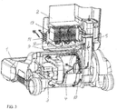
- eine schaubildliche Darstellung mit einer Luftführung der Abluft eines Sauggebläses im Bürstzusatz zum Ausblasfilter im aufgesetzten Filtergehäuse;
- Fig. 4
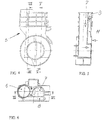
- eine Seitenansicht eines verschwenkbaren Verbindungselementes mit Luftführungskanälen;
- Fig. 5
- eine Schnittdarstellung gemäß Linie V-V der
Fig. 4 ; - Fig. 6
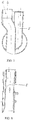
- eine Draufsicht gemäß
Fig. 4 ; - Fig. 7
- eine Schnittdarstellung gemäss Linie VII-VII der
Fig. 6 und - Fig. 8
- eine Schnittdarstellung gemäss Linie VIII-VIII der
Fig 4 . - Der dargestellte Bürststaubsauger besteht aus einem Bürstvorsatz 1 und einem aufsetzbaren Filtergehäuse 2 mit einer Handhabe, wobei der Bürstvorsatz 1 einen Motor 3 für ein Sauggebläse 4 und eine nicht näher dargestellte Bürstwalze aufweist. Die Verbindung zwischen Bürstvorsatz 1 und Filteregehäuse 2 erfolgt über ein verschwenkbares Verbindungselement 5 mit Luftführungskanälen 6,7 und 8 als Anschlussstutzen.
- Die Luftführungskanäle 6, 7 und 8 sind mit zugeordneten, weiterführenden Kanälen im Filtergehäuse 2 durch die Verbindung des Verbindungselementes 5 entsprechend verbunden und unabhängig von der Schwenkbewegung des Verbindungselementes 5 fortgeführt. Der Luftführungskanal 6 dient in bekannter Weise zur Zuführung für die mit Schmutz beladene Saugluft aus dem Bürstvorsatz 1 zum Filtergehäuse 2, und es erfolgt eine Luftrückführung der gefilterten Luft über den Luftführungskanal 7 zum Bürstvorsatz 1.
- Ein dritter Luftführungskanal als Abluftkanal 8 des verschwenkbaren Verbindungselementes 5 ist für die Abluft des Sauggebläses 4 angeordnet.
- Die Zuströmung zum dritten Luftführungskanal als Abluftkanal 8 für die Abluft des Sauggebläses 4 erfolgt stirnseitig zu einer dem Sauggebläse 4 zugeordneten verbindungselementenseitigen Anlagefläche, die mit zumindest einer entsprechenden Öffnung 10 versehen ist. Bei dem hier gezeigten Ausführungsbeispiel erfolgt die stirnseitige Zuströmung durch einen mantelförmigen, um das Gebläsegehäuse angeordneten Kanal 9 und korrespondierenden Öffnungen 10 in der der Zuströmfläche des Sauggebläses 4 zugeordneten Anlagefläche und einer durch den Luftführungskanal 8 vorgeschalteten Kammer 11 im verschwenkbaren Verbindungselement 5 mit zugeordneten Abdichtungen.
- Der Abluftkanal 8 führt im aufgesetzten Filtergehäuse 2 zu einer Filterkammer 12 mit einem eingesetzten Partikelfilter 13 und einem Luftauslass 14, der in diesem Fall eine Siebabdeckung aufweist.
- Offenbart ist ein Bürststaubsauger mit einem Bürstvorsatz zur Aufnahme einer angetriebenen Bürstwalze, wobei in dem Bürstvorsdatz mindestens ein elektrischer Motor für ein Sauggebläse sowie zum Antrieb der Bürstwalze angeordnet ist, und wobei in einem verschwenkbaren Verbindungselement zwischen dem Bürstvorsatz und einem Filtergehäuse zumindest drei Luftführungskanäle ausgebildet sind und durch den ersten Luftführungskanal eine Zuführung der mit Schmutz beladenen Saugluft aus dem Bürstvorsatz zum Filtergehäuse, durch den zweiten Luftführungskanal die Rückführung der gefilterten Luft zum Bürstvorsatz und durch den dritten Luftführkanal Abluft des Sauggebläses zurück zum Filtergehäuse zu einem Luftauslass erfolgt.
Claims (6)
- Bodenpflegegerät in Form eines Teppichreinigungsgeräts als Bürststaubsauger mit einem dem Boden zugewandten Bürstvorsatz (1) zur Aufnahme einer angetriebenen Bürstwalze, wobei der Bürstvorsatz über ein verschwenkbares Verbindungselement (5) mit Luftführungskanälen (6, 7) als Anschlussstutzen für ein aufsetzbares Filtergehäuse mit einer Handhabe als Handgriff über korrespondierende Anschlüsse verbindbar ist und der Bürstvorsatz (1) mindestens einen elektrischen Motor für ein Sauggebläse (4) sowie zum Antrieb der Bürstwalze aufnimmt und die Luftführungskanäle (6, 7) des verschwenkbaren Verbindungselementes (5) zur Zuführung für die mit Schmutz beladene Saugluft aus dem Bürstvorsatz zum Filtergehäuse und die Luftrückführung der gefilterten Luft über einen parallelen Luftführungskanal (6, 7) zum Bürstvorsatz geführt sind sowie eine Abluft vom Sauggebläse über Ausblasöffnungen erfolgt, dadurch gekennzeichnet, dass das verschwenkbare Verbindungselement (5) einen zusätzlichen dritten Luftführungskanal (8) als Abluftkanal (8) des Sauggebläses (4) im Bürstvorsatz (1) zu einer Zuführung zu einem Ausblasbereich im Filtergehäuse (2) mit einem Luftauslass (14) und zwischengeschaltetem Filter (13) aufweist.
- Bodenpflegegerät nach Anspruch 1, wobei eine Zuströmung zum dritten Luftführungskanal als Abluftkanal (8) für Abluft des Sauggebläses (4) stirnseitig zu einer dem Sauggebläse (4) zugeordneten Anlagefläche verläuft, die mit zumindest einer entsprechenden Öffnung (10) versehen ist.
- Bodenpflegegerät nach Anspruch 2, dadurch gekennzeichnet, dass die Zuströmung zum dritten Luftführungskanal als Abluftkanal (8) für Abluft des Sauggebläses (4) durch einen mantelförmigen um das Gebläsegehäuse angeordneten Kanal (9) und korrespondierende Öffnungen (10) in der der Zuströmseite des Sauggebläses (4) zugeordneten Anlagefläche mit Abdichtung und durch eine sich anschließende Kammer (11) im verschwenkbaren Verbindungselement (5) verläuft, die zum Luftrückführungskanal (7) abgedichtet ist.
- Bodenpflegegerät nach Anspruch 2 oder 3, dadurch gekennzeichnet, dass die Öffnungen (10) in der der Zuströmseite des Sauggebläses (4) zugeordnteten Anlagefläche mit Abdichtung ringförmig angeordnet sind und mit einer konzentrisch mit Dichtung um den Luftrückführungskanal (7) angeordneten Kammer (11) im verschwenkbaren Verbindungselement (5) als Zuströmung zum Abluftkanal (8) korrespondieren.
- Bodenpflegegerät nach einem der vorhergehenden Ansprüche, dadurch gekennzeichnet, dass der Abluftkanal (8) als zusätzlicher Rechteckkanal die beiden weiteren Luftführungskanäle (6,7) mit kreisförmigem Querschnitt seitlich begrenzt.
- Bodenpflegegerät nach einem der vorhergehenden Ansprüche, dadurch gekennzeichnet, dass der Ausblasbereich des Filtergehäuses (2) als Filterkammer (12) zur Aufnahme eines entnehmbaren Partikelfilters (13) ausgebildet ist und der Luftauslass (14) eine Siebabdeckung aufweist.
Applications Claiming Priority (2)
| Application Number | Priority Date | Filing Date | Title |
|---|---|---|---|
| DE102014006983 | 2014-05-05 | ||
| DE102014008441.8A DE102014008441B3 (de) | 2014-05-05 | 2014-06-06 | Bodenpflegegerät |
Publications (2)
| Publication Number | Publication Date |
|---|---|
| EP2941990A1 EP2941990A1 (de) | 2015-11-11 |
| EP2941990B1 true EP2941990B1 (de) | 2017-05-24 |
Family
ID=53759187
Family Applications (1)
| Application Number | Title | Priority Date | Filing Date |
|---|---|---|---|
| EP15166362.2A Active EP2941990B1 (de) | 2014-05-05 | 2015-05-05 | Bodenpflegegerät |
Country Status (4)
| Country | Link |
|---|---|
| US (1) | US9565982B2 (de) |
| EP (1) | EP2941990B1 (de) |
| CA (1) | CA2890806A1 (de) |
| DE (1) | DE102014008441B3 (de) |
Family Cites Families (5)
| Publication number | Priority date | Publication date | Assignee | Title |
|---|---|---|---|---|
| US4959885A (en) * | 1990-01-12 | 1990-10-02 | Royal Applicance Mfg. Co. | Vacuum cleaner |
| DE9104750U1 (de) * | 1991-04-18 | 1991-06-13 | Stein & Co GmbH, 5620 Velbert | Vorrichtung für Bürstsauger |
| US5946771A (en) * | 1997-01-09 | 1999-09-07 | The Hoover Company | Vacuum cleaner air exhaust arrangement |
| GB2357690B (en) * | 1997-01-10 | 2001-08-15 | White Consolidated Ind Inc | Air filtrating self-propelled upright vacuum cleaner |
| US6385810B1 (en) * | 2000-05-05 | 2002-05-14 | The Hoover Company | Latch arrangement for a vacuum cleaner dirt receptacle |
-
2014
- 2014-06-06 DE DE102014008441.8A patent/DE102014008441B3/de not_active Expired - Fee Related
-
2015
- 2015-05-05 CA CA2890806A patent/CA2890806A1/en not_active Abandoned
- 2015-05-05 EP EP15166362.2A patent/EP2941990B1/de active Active
- 2015-05-05 US US14/704,009 patent/US9565982B2/en active Active
Also Published As
| Publication number | Publication date |
|---|---|
| US9565982B2 (en) | 2017-02-14 |
| CA2890806A1 (en) | 2015-11-05 |
| DE102014008441B3 (de) | 2015-08-20 |
| EP2941990A1 (de) | 2015-11-11 |
| US20150313429A1 (en) | 2015-11-05 |
Similar Documents
| Publication | Publication Date | Title |
|---|---|---|
| EP3832213B1 (de) | Dunstabzugsvorrichtung zum abzug von kochdünsten nach unten | |
| EP2431132B1 (de) | Handgeführtes Arbeitsgerät | |
| DE740860C (de) | Elektrisch angetriebener Staubsauger | |
| DE19645096A1 (de) | Luftreinigungsgerät | |
| DE202014100753U1 (de) | Handgebläse | |
| DE202014100752U1 (de) | Handgebläse | |
| DE202009008286U1 (de) | Kochdunst-Eintrittsvorrichtung mit abnehmbarer deckelförmiger Verschließeinrichtung | |
| DE10041906B4 (de) | Schleifgerät mit Staubabsaugung | |
| EP1873890A3 (de) | Universalmotor mit Einrichtung zum Entfernen von Staub | |
| EP3860821A1 (de) | Absaugvorrichtung für eine kernbohreinrichtung | |
| DE102016117537A1 (de) | Dunstabzugsvorrichtung mit Ansaugstutzen | |
| EP2941991B1 (de) | Bodenpflegegerät | |
| DE102013002841A1 (de) | Bodendüse mit einer Kombination aus Bürstenwalze und Saugdüse (AP Düse) | |
| DE102014008441B3 (de) | Bodenpflegegerät | |
| EP3788264B1 (de) | Luftreinigungsvorrichtung, insbesondere für kochwrasen, und verwendung davon | |
| DE1237276B (de) | Als Stielstaubsauger ausgebildetes Fussboden-pflegegeraet mit elektromotorisch angetriebenen umlaufenden Pflegewerkzeugen | |
| EP1639931B1 (de) | Gehäuseunterteil eines Handstaubsaugers | |
| DE202010004866U1 (de) | Unterdruck-Staubabsaugungsanordnung für angetriebene Werkzeuge | |
| WO2010018086A1 (de) | Staubsauger | |
| DE102008053164B4 (de) | Ventilator für eine Gasreinigungsanlage | |
| EP2941992B1 (de) | Bodenpflegegerät | |
| DE529132C (de) | Staubsauger | |
| DE705678C (de) | Schleifmaschine, insbesondere Fraes- und Ausputzmaschine fuer Schuhwerk | |
| EP2123204B1 (de) | Vorrichtung zur regulierung des saugluftstroms eines saugers | |
| DE226214C (de) |
Legal Events
| Date | Code | Title | Description |
|---|---|---|---|
| PUAI | Public reference made under article 153(3) epc to a published international application that has entered the european phase |
Free format text: ORIGINAL CODE: 0009012 |
|
| AK | Designated contracting states |
Kind code of ref document: A1 Designated state(s): AL AT BE BG CH CY CZ DE DK EE ES FI FR GB GR HR HU IE IS IT LI LT LU LV MC MK MT NL NO PL PT RO RS SE SI SK SM TR |
|
| AX | Request for extension of the european patent |
Extension state: BA ME |
|
| 17P | Request for examination filed |
Effective date: 20160511 |
|
| RBV | Designated contracting states (corrected) |
Designated state(s): AL AT BE BG CH CY CZ DE DK EE ES FI FR GB GR HR HU IE IS IT LI LT LU LV MC MK MT NL NO PL PT RO RS SE SI SK SM TR |
|
| GRAP | Despatch of communication of intention to grant a patent |
Free format text: ORIGINAL CODE: EPIDOSNIGR1 |
|
| STAA | Information on the status of an ep patent application or granted ep patent |
Free format text: STATUS: GRANT OF PATENT IS INTENDED |
|
| INTG | Intention to grant announced |
Effective date: 20161208 |
|
| GRAS | Grant fee paid |
Free format text: ORIGINAL CODE: EPIDOSNIGR3 |
|
| GRAA | (expected) grant |
Free format text: ORIGINAL CODE: 0009210 |
|
| STAA | Information on the status of an ep patent application or granted ep patent |
Free format text: STATUS: THE PATENT HAS BEEN GRANTED |
|
| AK | Designated contracting states |
Kind code of ref document: B1 Designated state(s): AL AT BE BG CH CY CZ DE DK EE ES FI FR GB GR HR HU IE IS IT LI LT LU LV MC MK MT NL NO PL PT RO RS SE SI SK SM TR |
|
| REG | Reference to a national code |
Ref country code: GB Ref legal event code: FG4D Free format text: NOT ENGLISH |
|
| REG | Reference to a national code |
Ref country code: CH Ref legal event code: EP |
|
| REG | Reference to a national code |
Ref country code: IE Ref legal event code: FG4D Free format text: LANGUAGE OF EP DOCUMENT: GERMAN |
|
| REG | Reference to a national code |
Ref country code: AT Ref legal event code: REF Ref document number: 895580 Country of ref document: AT Kind code of ref document: T Effective date: 20170615 |
|
| REG | Reference to a national code |
Ref country code: DE Ref legal event code: R096 Ref document number: 502015001101 Country of ref document: DE |
|
| REG | Reference to a national code |
Ref country code: NL Ref legal event code: FP |
|
| REG | Reference to a national code |
Ref country code: LT Ref legal event code: MG4D |
|
| PG25 | Lapsed in a contracting state [announced via postgrant information from national office to epo] |
Ref country code: NO Free format text: LAPSE BECAUSE OF FAILURE TO SUBMIT A TRANSLATION OF THE DESCRIPTION OR TO PAY THE FEE WITHIN THE PRESCRIBED TIME-LIMIT Effective date: 20170824 Ref country code: FI Free format text: LAPSE BECAUSE OF FAILURE TO SUBMIT A TRANSLATION OF THE DESCRIPTION OR TO PAY THE FEE WITHIN THE PRESCRIBED TIME-LIMIT Effective date: 20170524 Ref country code: HR Free format text: LAPSE BECAUSE OF FAILURE TO SUBMIT A TRANSLATION OF THE DESCRIPTION OR TO PAY THE FEE WITHIN THE PRESCRIBED TIME-LIMIT Effective date: 20170524 Ref country code: GR Free format text: LAPSE BECAUSE OF FAILURE TO SUBMIT A TRANSLATION OF THE DESCRIPTION OR TO PAY THE FEE WITHIN THE PRESCRIBED TIME-LIMIT Effective date: 20170825 Ref country code: LT Free format text: LAPSE BECAUSE OF FAILURE TO SUBMIT A TRANSLATION OF THE DESCRIPTION OR TO PAY THE FEE WITHIN THE PRESCRIBED TIME-LIMIT Effective date: 20170524 Ref country code: ES Free format text: LAPSE BECAUSE OF FAILURE TO SUBMIT A TRANSLATION OF THE DESCRIPTION OR TO PAY THE FEE WITHIN THE PRESCRIBED TIME-LIMIT Effective date: 20170524 |
|
| PG25 | Lapsed in a contracting state [announced via postgrant information from national office to epo] |
Ref country code: IS Free format text: LAPSE BECAUSE OF FAILURE TO SUBMIT A TRANSLATION OF THE DESCRIPTION OR TO PAY THE FEE WITHIN THE PRESCRIBED TIME-LIMIT Effective date: 20170924 Ref country code: SE Free format text: LAPSE BECAUSE OF FAILURE TO SUBMIT A TRANSLATION OF THE DESCRIPTION OR TO PAY THE FEE WITHIN THE PRESCRIBED TIME-LIMIT Effective date: 20170524 Ref country code: RS Free format text: LAPSE BECAUSE OF FAILURE TO SUBMIT A TRANSLATION OF THE DESCRIPTION OR TO PAY THE FEE WITHIN THE PRESCRIBED TIME-LIMIT Effective date: 20170524 Ref country code: BG Free format text: LAPSE BECAUSE OF FAILURE TO SUBMIT A TRANSLATION OF THE DESCRIPTION OR TO PAY THE FEE WITHIN THE PRESCRIBED TIME-LIMIT Effective date: 20170824 Ref country code: LV Free format text: LAPSE BECAUSE OF FAILURE TO SUBMIT A TRANSLATION OF THE DESCRIPTION OR TO PAY THE FEE WITHIN THE PRESCRIBED TIME-LIMIT Effective date: 20170524 |
|
| PG25 | Lapsed in a contracting state [announced via postgrant information from national office to epo] |
Ref country code: EE Free format text: LAPSE BECAUSE OF FAILURE TO SUBMIT A TRANSLATION OF THE DESCRIPTION OR TO PAY THE FEE WITHIN THE PRESCRIBED TIME-LIMIT Effective date: 20170524 Ref country code: RO Free format text: LAPSE BECAUSE OF FAILURE TO SUBMIT A TRANSLATION OF THE DESCRIPTION OR TO PAY THE FEE WITHIN THE PRESCRIBED TIME-LIMIT Effective date: 20170524 Ref country code: SK Free format text: LAPSE BECAUSE OF FAILURE TO SUBMIT A TRANSLATION OF THE DESCRIPTION OR TO PAY THE FEE WITHIN THE PRESCRIBED TIME-LIMIT Effective date: 20170524 Ref country code: DK Free format text: LAPSE BECAUSE OF FAILURE TO SUBMIT A TRANSLATION OF THE DESCRIPTION OR TO PAY THE FEE WITHIN THE PRESCRIBED TIME-LIMIT Effective date: 20170524 Ref country code: CZ Free format text: LAPSE BECAUSE OF FAILURE TO SUBMIT A TRANSLATION OF THE DESCRIPTION OR TO PAY THE FEE WITHIN THE PRESCRIBED TIME-LIMIT Effective date: 20170524 |
|
| REG | Reference to a national code |
Ref country code: DE Ref legal event code: R097 Ref document number: 502015001101 Country of ref document: DE |
|
| PG25 | Lapsed in a contracting state [announced via postgrant information from national office to epo] |
Ref country code: SM Free format text: LAPSE BECAUSE OF FAILURE TO SUBMIT A TRANSLATION OF THE DESCRIPTION OR TO PAY THE FEE WITHIN THE PRESCRIBED TIME-LIMIT Effective date: 20170524 Ref country code: PL Free format text: LAPSE BECAUSE OF FAILURE TO SUBMIT A TRANSLATION OF THE DESCRIPTION OR TO PAY THE FEE WITHIN THE PRESCRIBED TIME-LIMIT Effective date: 20170524 |
|
| PLBE | No opposition filed within time limit |
Free format text: ORIGINAL CODE: 0009261 |
|
| STAA | Information on the status of an ep patent application or granted ep patent |
Free format text: STATUS: NO OPPOSITION FILED WITHIN TIME LIMIT |
|
| 26N | No opposition filed |
Effective date: 20180227 |
|
| REG | Reference to a national code |
Ref country code: FR Ref legal event code: PLFP Year of fee payment: 4 |
|
| PG25 | Lapsed in a contracting state [announced via postgrant information from national office to epo] |
Ref country code: SI Free format text: LAPSE BECAUSE OF FAILURE TO SUBMIT A TRANSLATION OF THE DESCRIPTION OR TO PAY THE FEE WITHIN THE PRESCRIBED TIME-LIMIT Effective date: 20170524 |
|
| PG25 | Lapsed in a contracting state [announced via postgrant information from national office to epo] |
Ref country code: MT Free format text: LAPSE BECAUSE OF FAILURE TO SUBMIT A TRANSLATION OF THE DESCRIPTION OR TO PAY THE FEE WITHIN THE PRESCRIBED TIME-LIMIT Effective date: 20170524 |
|
| REG | Reference to a national code |
Ref country code: CH Ref legal event code: PL |
|
| REG | Reference to a national code |
Ref country code: BE Ref legal event code: MM Effective date: 20180531 |
|
| PG25 | Lapsed in a contracting state [announced via postgrant information from national office to epo] |
Ref country code: MC Free format text: LAPSE BECAUSE OF FAILURE TO SUBMIT A TRANSLATION OF THE DESCRIPTION OR TO PAY THE FEE WITHIN THE PRESCRIBED TIME-LIMIT Effective date: 20170524 |
|
| REG | Reference to a national code |
Ref country code: IE Ref legal event code: MM4A |
|
| PG25 | Lapsed in a contracting state [announced via postgrant information from national office to epo] |
Ref country code: LI Free format text: LAPSE BECAUSE OF NON-PAYMENT OF DUE FEES Effective date: 20180531 Ref country code: CH Free format text: LAPSE BECAUSE OF NON-PAYMENT OF DUE FEES Effective date: 20180531 |
|
| PG25 | Lapsed in a contracting state [announced via postgrant information from national office to epo] |
Ref country code: LU Free format text: LAPSE BECAUSE OF NON-PAYMENT OF DUE FEES Effective date: 20180505 |
|
| PG25 | Lapsed in a contracting state [announced via postgrant information from national office to epo] |
Ref country code: IE Free format text: LAPSE BECAUSE OF NON-PAYMENT OF DUE FEES Effective date: 20180505 |
|
| PG25 | Lapsed in a contracting state [announced via postgrant information from national office to epo] |
Ref country code: BE Free format text: LAPSE BECAUSE OF NON-PAYMENT OF DUE FEES Effective date: 20180531 |
|
| PGFP | Annual fee paid to national office [announced via postgrant information from national office to epo] |
Ref country code: NL Payment date: 20190521 Year of fee payment: 5 |
|
| PGFP | Annual fee paid to national office [announced via postgrant information from national office to epo] |
Ref country code: FR Payment date: 20190521 Year of fee payment: 5 |
|
| PG25 | Lapsed in a contracting state [announced via postgrant information from national office to epo] |
Ref country code: TR Free format text: LAPSE BECAUSE OF FAILURE TO SUBMIT A TRANSLATION OF THE DESCRIPTION OR TO PAY THE FEE WITHIN THE PRESCRIBED TIME-LIMIT Effective date: 20170524 |
|
| PG25 | Lapsed in a contracting state [announced via postgrant information from national office to epo] |
Ref country code: PT Free format text: LAPSE BECAUSE OF FAILURE TO SUBMIT A TRANSLATION OF THE DESCRIPTION OR TO PAY THE FEE WITHIN THE PRESCRIBED TIME-LIMIT Effective date: 20170524 |
|
| PG25 | Lapsed in a contracting state [announced via postgrant information from national office to epo] |
Ref country code: CY Free format text: LAPSE BECAUSE OF FAILURE TO SUBMIT A TRANSLATION OF THE DESCRIPTION OR TO PAY THE FEE WITHIN THE PRESCRIBED TIME-LIMIT Effective date: 20170524 Ref country code: MK Free format text: LAPSE BECAUSE OF NON-PAYMENT OF DUE FEES Effective date: 20170524 Ref country code: HU Free format text: LAPSE BECAUSE OF FAILURE TO SUBMIT A TRANSLATION OF THE DESCRIPTION OR TO PAY THE FEE WITHIN THE PRESCRIBED TIME-LIMIT; INVALID AB INITIO Effective date: 20150505 |
|
| PG25 | Lapsed in a contracting state [announced via postgrant information from national office to epo] |
Ref country code: AL Free format text: LAPSE BECAUSE OF FAILURE TO SUBMIT A TRANSLATION OF THE DESCRIPTION OR TO PAY THE FEE WITHIN THE PRESCRIBED TIME-LIMIT Effective date: 20170524 |
|
| REG | Reference to a national code |
Ref country code: NL Ref legal event code: MM Effective date: 20200601 |
|
| PG25 | Lapsed in a contracting state [announced via postgrant information from national office to epo] |
Ref country code: NL Free format text: LAPSE BECAUSE OF NON-PAYMENT OF DUE FEES Effective date: 20200601 |
|
| PG25 | Lapsed in a contracting state [announced via postgrant information from national office to epo] |
Ref country code: FR Free format text: LAPSE BECAUSE OF NON-PAYMENT OF DUE FEES Effective date: 20200531 |
|
| REG | Reference to a national code |
Ref country code: AT Ref legal event code: MM01 Ref document number: 895580 Country of ref document: AT Kind code of ref document: T Effective date: 20200505 |
|
| PG25 | Lapsed in a contracting state [announced via postgrant information from national office to epo] |
Ref country code: AT Free format text: LAPSE BECAUSE OF NON-PAYMENT OF DUE FEES Effective date: 20200505 |
|
| P01 | Opt-out of the competence of the unified patent court (upc) registered |
Effective date: 20230527 |
|
| PGFP | Annual fee paid to national office [announced via postgrant information from national office to epo] |
Ref country code: DE Payment date: 20250402 Year of fee payment: 11 |
|
| PGFP | Annual fee paid to national office [announced via postgrant information from national office to epo] |
Ref country code: IT Payment date: 20250530 Year of fee payment: 11 |
|
| PGFP | Annual fee paid to national office [announced via postgrant information from national office to epo] |
Ref country code: GB Payment date: 20260324 Year of fee payment: 12 |