EP2941205B1 - Systeme für distale resektion - Google Patents
Systeme für distale resektion Download PDFInfo
- Publication number
- EP2941205B1 EP2941205B1 EP14701633.1A EP14701633A EP2941205B1 EP 2941205 B1 EP2941205 B1 EP 2941205B1 EP 14701633 A EP14701633 A EP 14701633A EP 2941205 B1 EP2941205 B1 EP 2941205B1
- Authority
- EP
- European Patent Office
- Prior art keywords
- guide
- drill
- valgus
- femur
- distal
- Prior art date
- Legal status (The legal status is an assumption and is not a legal conclusion. Google has not performed a legal analysis and makes no representation as to the accuracy of the status listed.)
- Active
Links
- 0 CCC(C)C*(C)CN=O Chemical compound CCC(C)C*(C)CN=O 0.000 description 1
Images


Classifications
-
- A—HUMAN NECESSITIES
- A61—MEDICAL OR VETERINARY SCIENCE; HYGIENE
- A61B—DIAGNOSIS; SURGERY; IDENTIFICATION
- A61B17/00—Surgical instruments, devices or methods
- A61B17/14—Surgical saws
- A61B17/15—Guides therefor
- A61B17/154—Guides therefor for preparing bone for knee prosthesis
- A61B17/155—Cutting femur
-
- A—HUMAN NECESSITIES
- A61—MEDICAL OR VETERINARY SCIENCE; HYGIENE
- A61B—DIAGNOSIS; SURGERY; IDENTIFICATION
- A61B17/00—Surgical instruments, devices or methods
- A61B17/16—Instruments for performing osteoclasis; Drills or chisels for bones; Trepans
- A61B17/17—Guides or aligning means for drills, mills, pins or wires
- A61B17/1739—Guides or aligning means for drills, mills, pins or wires specially adapted for particular parts of the body
- A61B17/1764—Guides or aligning means for drills, mills, pins or wires specially adapted for particular parts of the body for the knee
Definitions
- the present disclosure relates to systems for preparing a distal end of a femur for receiving a knee prosthesis.
- a knee prosthesis can include a femoral component that is configured to replace the articular surface of one or both of the natural condyles at a distal end of a femur.
- the femoral component articulates with a tibial component attached to a proximal end of a patient's tibia, so that the knee prosthesis completely replaces the articular surfaces of the natural knee femur and tibia.
- the surgery that is required to install knee prostheses is invasive and typically involves the use of numerous instruments to, among other things, establish femoral alignment (e.g ., using a femoral valgus alignment guide); establish external rotation ( e.g. , using an anterior referencing femoral sizing guide); and size the femur.
- the use of multiple instruments often requires the surgeon to place and remove each instrument as he or she progresses through a surgical procedure. Each time, the surgeon must establish or re-establish a correct positioning for each subsequent instrument used during the surgical procedure. Establishing or re-establishing the correct positioning for each instrument can be cumbersome and time consuming.
- US2006/241634 is directed to an anti-backout stylus instrument assembly.
- the present inventors recognize that there is a need for new systems for performing the installation of knee prostheses that include fewer instruments, fewer steps, and/or less time to accomplish the installation of the prostheses.
- the embodiments of the present systems accomplish this goal.
- the present invention is defined in claim 1 and defines a system for preparing a distal end of a femur for receiving a knee prosthesis.
- a method can include installing a valgus guide onto an intermedullary rod, coupling a drill guide with said valgus guide, resting a boom tip of said drill guide on a high part of the femur, drilling a hole into a distal portion of a medial condyle using a first drill hole of said drill guide and drilling a hole into a distal portion of a lateral condyle using a second drill hole of said drill guide, and, subsequent to drilling the first and second drill holes, resecting the distal portion of the medial condyle of the femur and the distal portion of the lateral condyle of the femur.
- the method can further include decoupling said drill guide from said valgus guide and replacing said drill guide with a resection tower.
- a system can include a valgus
- a method for preparing a distal end of a femur for receiving a knee prosthesis comprises installing a valgus guide, including a first aperture for slidably accepting an intramedullary rod and one or more second apertures for accepting a drill guide, onto the intramedullary rod such that it contacts at least a distal portion of a medial condyle of the femur; coupling said drill guide with said valgus guide, including sliding one or more drill guide posts into said one or more second apertures of the valgus guide and locating a first drill hole of the drill guide substantially over the distal portion of the medial condyle of the femur and a second drill hole of the drill guide substantially over the distal portion of the lateral condyle of the femur intramedullary; resting a boom tip of said drill guide on a high part of the femur to align said first drill hole and said second drill hole; drilling a hole into the distal portion of the medial condy
- the method is optionally configured such that locating the first and second drill holes over the distal portion of the medial and lateral condyles of the femur includes orienting the first and second drill holes along an axis substantially parallel to an axis of the intramedullary rod.
- the method optionally further comprises decoupling said drill guide from said valgus guide and replacing said drill guide with a resection tower.
- the resection tower includes a distal cut guide and one or more posts configured to slide into said one or more second apertures on the valgus guide.
- the method is optionally configured such that resecting the distal portion of the medial and lateral condyles of the femur includes inserting a saw blade into the distal cut guide of the resection tower.
- the method optionally further comprises coupling a cut guide with the distal end of the femur, including inserting a first post of the cut guide into the hole drilled into said distal portion of the medial condyle and inserting a second post of the cut guide into the hole drilled into said distal portion of the lateral condyle.
- the method optionally further comprises verifying a size of the femur before coupling the cut guide with the distal end of the femur.
- the method is optionally configured such that resting the boom tip on the high part of the femur includes establishing femoral alignment and external rotation.
- the method optionally further comprises coupling a knee prosthesis with the distal end of the femur.
- a system comprises a valgus guide including a first aperture for slidably accepting an intramedullary rod and one or more second apertures; a drill guide, couplable with the valgus guide, including one or more drill guide posts, the one or more drill guide posts sized and shaped to be received by the one or more second apertures of the valgus guide; and a resection tower, couplable with the valgus guide, including one or more tower posts, the one or more tower posts sized and shaped to be received by the one or more second apertures of the valgus guide.
- the system optionally includes a boom tip.
- the system is optionally configured such that said drill guide includes a first drill hole and a second drill hole, the first and second drill holes are positioned on said drill guide to be respectively located over a distal portion of medial and lateral condyles when said drill guide is coupled with said valgus guide.
- the system optionally further comprises one or more drill bits sized and shaped to be received by the first and second drill holes.
- the system is optionally configured such that an orientation of an axis of the first aperture and an orientation of an axis of each of the one or more second apertures of said valgus guide are perpendicular.
- the system is optionally configured such that said resection tower includes a distal cut guide.
- the system optionally further comprises a saw blade sized and shaped to be received by the distal cut guide.
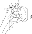
- embodiments of the present invention relate to systems for preparing a distal end of a femur 112 for receiving a knee prosthesis.
- a method including the use of system components, can comprise:
- the valgus guide 100 contacts a distal portion of a medial condyle 104 of the femur 112 and a distal portion of a lateral condyle 106 of the femur 112.
- rotation may be established.
- internal/external rotation may be established by using the valgus guide 100 rather than a separate guide, such as a femoral sizer.
- internal/external rotation may be established by aligning the axis 201 ( see FIG. 2A ) between the first drill hole 208 and the second drill hole 210 such that the axis 201 is, for example, parallel to the epicondylar axis of the femur or perpendicular to Whiteside's line.
- the boom 204 is slidably and rotatably engaged, at notch 205 ( see FIG. 2C ), with the drill guide 200, such that the boom tip 206 may be located by moving the boom204 (and the tip 206) backward or forward along axis 209 and rotating the boom 204 (and the tip 206) about notch 205.
- the boom 204 is moved and rotated, as necessary, to position the boom tip 206 along a portion of the anterolateral ridge, about one-third to one-half "up" the peak, between the high and low point of the anterolateral ridge.
- the boom comprises markings 207 corresponding to the femur size ( e.g. , sizes 1, 7, and 12, with other sizes that may be interpolated). The markings 207, in turn, correlate with the saw blade exit point for the indicated femur size.
- the valgus guide 100 comprises a fixed angle valgus guide or an adjustable angle valgus guide.
- the resecting step recited above removes the distal portion of the medial condyle of the femur 112 and the distal portion of the lateral condyle of the femur 112.
- the resecting step can be performed using existing tools and methods known in the art.
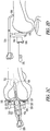
- FIG. 4 also shows the drilled holes 400 and 402 corresponding to the holes that were drilled into the distal portions of the medial and lateral condyles using the first drill hole 208 and second drill hole 210 of the drill guide 200, respectively.
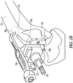
- the resecting step further comprises removing said drill guide 200 and replacing said drill guide with a resection tower 300 comprising a distal cut guide 302; one or more resection tower posts 304 configured to slide into said one or more second apertures 110 on the valgus guide 200, said distal cut guide 300 comprising one or more slots 306 configured to accept a saw blade (not shown), e.g ., an oscillating saw blade.
- the distal cut guide 302 of the resection tower 300 is configured to be moveable along the same axis as the intramedullary rod 102, so as to allow for adjustment of the cutting depth; that is, how deeply one can cut into the distal portion of the femur 112.
- the cutting depth can be adjusted by setting the toggle 308 to an unlocked position (toggle shown in a locked position in FIG. 3 ).
- the toggle 308 is in the unlocked position, the distal cut guide 302 can translate along shaft 310 from a minimum resection depth to a maximum resection depth.
- the distal cut guide 302 when the distal cut guide 302 is set to the minimum resection depth, the amount of the distal portion of the femur, which includes the distal portion of the medial condyle 104 of the femur 112 and the distal portion of the lateral condyle 106 of the femur 112, will not be as large as when the distal cut guide 302 is set to the maximum resection depth.
- the distal cut guide 302 is set to the minimum resection depth, that corresponds, in some embodiments, to a 10 mm distal resection.
- the maximum resection depth corresponds to a 14 mm distal resection.
- toggle 308 can be replaced by any other mechanism that allows the distal cut guide 302 to translate along shaft 310 from a minimum resection depth to a maximum (or deeper) resection depth.
- the method for preparing a distal end of a femur for receiving a knee prosthesis further comprises installing a cut guide 500 comprising one or more slots 502, 504, 506, and 508 configured to accept a saw blade and first and second cut guide posts 510 (only one shown in FIG. 5 ), said first post 510 configured to fit into the hole 400 drilled into the distal portion of the lateral condyle and said second post (not shown) configured to fit into the hole 402 drilled into said distal portion of the medial condyle.
- the slots 502, 504, 506, and 508 accept a saw blade and are used to perform an anterior resection 602, a posterior resection 604, a posterior chamfer resection 606, and an anterior chamfer resection 608, respectively.
- the size of the femur is optionally verified prior to installing the cut guide 500.
- the method for preparing a distal end of a femur for receiving a knee prosthesis improves upon some known systems and methods for performing the installation of knee prostheses because it requires fewer instruments, fewer steps, and less time to accomplish the installation of the prostheses.
- one known method requires sizing the distal femur (after cutting) with at least one instrument, before setting the external rotation using at least a second instrument.
- Another known method requires establishing femoral alignment with at least one instrument; sizing the distal femur (after cutting) with at least a second instrument; and setting the external rotation with at least a third instrument.
- Another known method requires setting the external rotation with at least one instrument; establishing femoral alignment with at least a second instrument, and sizing the femur with at least a third instrument.
- the method for preparing a distal end of a femur for receiving a knee prosthesis of the embodiments of the invention sets external rotation and femoral alignment with one instrument and effectively sizes the distal femur with the same instrument, though the sizing may be verified for good measure.
Landscapes
- Health & Medical Sciences (AREA)
- Surgery (AREA)
- Life Sciences & Earth Sciences (AREA)
- Biomedical Technology (AREA)
- Public Health (AREA)
- Oral & Maxillofacial Surgery (AREA)
- Nuclear Medicine, Radiotherapy & Molecular Imaging (AREA)
- Veterinary Medicine (AREA)
- Dentistry (AREA)
- Engineering & Computer Science (AREA)
- Orthopedic Medicine & Surgery (AREA)
- Heart & Thoracic Surgery (AREA)
- Medical Informatics (AREA)
- Molecular Biology (AREA)
- Animal Behavior & Ethology (AREA)
- General Health & Medical Sciences (AREA)
- Physical Education & Sports Medicine (AREA)
- Transplantation (AREA)
- Surgical Instruments (AREA)
- Prostheses (AREA)
Claims (15)
- System zum Vorbereiten eines distalen Endes eines Femurs für das Aufnehmen einer Knieprothese, wobei das System Folgendes umfasst:eine Schiefstellungsführung (100), die eine erste Öffnung (108) zum gleitenden Empfangen eines intramedullären Stabes (102) und eine oder mehrere zweite Öffnungen (110) enthält;einen Resektionsrückhalt (300), der mit der Schiefstellungsführung koppelbar ist, der einen oder mehrere Rückhaltepfosten (304) enthält, wobei der eine oder die mehreren Rückhaltepfosten dimensioniert und geformt sind, um in dem einen oder den mehreren zweiten Öffnungen der Schiefstellungsführung aufgenommen zu werden, dadurch gekennzeichnet, dass das System weiter eine Bohrführung (200) umfasst, die mit der Schiefstellungsführung koppelbar ist, die eine oder mehrere Bohrführungspfosten (202) enthält und dimensioniert und geformt ist, um von der einen oder den mehreren zweiten Öffnungen der Schiefstellungsführung aufgenommen zu werden, wobei die Bohrführung konfiguriert ist, um eine Bohrspitze zu empfangen, die entlang einer Achse im Wesentlichen parallel zu dem intramedullären Stab orientiert ist.
- System nach Anspruch 1, wobei die Bohrführung einen Ausleger (204) und eine Auslegerspitze (206) enthält.
- System nach Anspruch 1 oder 2, wobei die Bohrführung ein erstes Bohrloch (208) und ein zweites Bohrloch (210) enthält, wobei das erste und zweite Bohrloch auf der Bohrführung positioniert sind, um jeweils über einem distalen Abschnitt medialer und lateraler Kondylen positioniert zu werden, wenn die Bohrführung mit der Schiefstellungsführung gekoppelt wird.
- System nach Anspruch 3, weiter umfassend eine oder mehrere Bohrspitzen, die dimensioniert und geformt sind, um von dem ersten und zweiten Bohrloch aufgenommen zu werden.
- System nach einem der Ansprüche 1-4, wobei eine Orientierung einer Achse der ersten Öffnung und eine Orientierung einer Achse jeder der einen oder mehreren zweiten Öffnungen der Schiefstellungsführung senkrecht sind.
- System nach einem der Ansprüche 1-4, wobei der Resektionsrückhalt eine distale Schneideführung (302) enthält.
- System nach Anspruch 6, weiter umfassend ein Sägeblatt, das dimensioniert und geformt ist, um von der distalen Schneideführung aufgenommen zu werden.
- System nach Anspruch 2, wobei die Auslegerspitze konfiguriert ist, um auf einem hohen Teil eines Femurs zu liegen, um ein erstes Bohrloch (208) und ein zweites Bohrloch (210) aneinander auszurichten, die in der Bohrführung enthalten sind, und wobei das erste und zweite Bohrloch auf der Bohrführung positioniert sind, um jeweils über einem distalen Abschnitt medialer und lateraler Kondylen positioniert zu werden, wenn die Bohrführung mit der Schiefstellungsführung gekoppelt wird.
- System nach Anspruch 8, wobei sich der Ausleger und die Auslegerspitze in Bezug auf die Bohrführung gleitbar und drehbar im Eingriff befinden.
- System nach Anspruch 2, wobei der Ausleger und die Auslegerspitze einer Femurgröße entsprechende Markierungen (207) umfassen, und wobei die Markierungen mit dem Sägeblattausgangspunkt für eine angegebene Femurgröße korrelieren.
- System nach Anspruch 1, wobei die Schiefstellungsführung eine Schiefstellungsführung mit festem Winkel ist.
- System nach Anspruch 1, wobei die Schiefstellungsführung eine verstellbare Schiefstellungsführung ist.
- System nach Anspruch 6, wobei die distale Schneideführung konfiguriert ist, um entlang der gleichen Achse bewegt zu werden wie der intramedulläre Stab.
- System nach Anspruch 13, wobei die distale Schneideführung weiter einen Knebel (308) und einen Schaft (310) umfasst, wobei der Knebel eine verriegelte und eine entriegelte Position aufweist und sich die distale Schneideführung entlang des Schafts verschieben kann, wenn sich der Knebel in der entriegelten Position befindet.
- System nach Anspruch 1, wobei die Schiefstellungsführung konfiguriert ist, um eine interne/externe Drehung einzurichten.
Applications Claiming Priority (2)
| Application Number | Priority Date | Filing Date | Title |
|---|---|---|---|
| US201361749569P | 2013-01-07 | 2013-01-07 | |
| PCT/US2014/010473 WO2014107716A1 (en) | 2013-01-07 | 2014-01-07 | Distal resection systems and methods |
Publications (2)
| Publication Number | Publication Date |
|---|---|
| EP2941205A1 EP2941205A1 (de) | 2015-11-11 |
| EP2941205B1 true EP2941205B1 (de) | 2017-03-29 |
Family
ID=50023872
Family Applications (1)
| Application Number | Title | Priority Date | Filing Date |
|---|---|---|---|
| EP14701633.1A Active EP2941205B1 (de) | 2013-01-07 | 2014-01-07 | Systeme für distale resektion |
Country Status (3)
| Country | Link |
|---|---|
| US (1) | US9713477B2 (de) |
| EP (1) | EP2941205B1 (de) |
| WO (1) | WO2014107716A1 (de) |
Families Citing this family (5)
| Publication number | Priority date | Publication date | Assignee | Title |
|---|---|---|---|---|
| EP2941205B1 (de) | 2013-01-07 | 2017-03-29 | Zimmer, Inc. | Systeme für distale resektion |
| US10357255B2 (en) | 2015-10-08 | 2019-07-23 | Howmedica Osteonics Corp. | Globalized total knee instrumentation |
| US11147649B2 (en) | 2015-10-14 | 2021-10-19 | Ecential Robotics | Device for minimally invasive attachment of a tracker and/or a registration phantom to a patient's bone |
| CN112617960B (zh) * | 2020-12-31 | 2022-02-08 | 北京长木谷医疗科技有限公司 | 全膝关节置换手术用股骨导板及其使用方法 |
| CN115969541B (zh) * | 2023-03-20 | 2023-07-07 | 北京爱康宜诚医疗器材有限公司 | 一种股骨髁远端磨削定位工具 |
Family Cites Families (13)
| Publication number | Priority date | Publication date | Assignee | Title |
|---|---|---|---|---|
| US5720752A (en) * | 1993-11-08 | 1998-02-24 | Smith & Nephew, Inc. | Distal femoral cutting guide apparatus with anterior or posterior referencing for use in knee joint replacement surgery |
| US5486178A (en) | 1994-02-16 | 1996-01-23 | Hodge; W. Andrew | Femoral preparation instrumentation system and method |
| US5662656A (en) | 1995-12-08 | 1997-09-02 | Wright Medical Technology, Inc. | Instrumentation and method for distal femoral sizing, and anterior and distal femoral resections |
| EP1691692B1 (de) | 2003-11-14 | 2011-01-19 | Smith & Nephew, Inc. | Verstellbare chirurgische schneidesysteme |
| US20060195111A1 (en) | 2005-01-25 | 2006-08-31 | Orthosoft Inc. | Universal positioning block assembly |
| US8734453B2 (en) * | 2005-02-21 | 2014-05-27 | Wright Medical Technology, Inc. | Instruments for minimally invasive surgery total knee arthroplasty |
| AU2006299438B9 (en) | 2005-10-03 | 2013-07-18 | Smith & Nephew, Inc. | Locking instrument assembly |
| US8702714B2 (en) | 2006-03-09 | 2014-04-22 | Microsoft Orthopedics Holdings Inc. | Instruments for total knee arthroplasty |
| WO2008043021A2 (en) | 2006-10-04 | 2008-04-10 | Smith & Nephew, Inc. | Device and method for distal resections of a knee prosthetic |
| PT2073726E (pt) | 2006-10-11 | 2013-08-26 | Ignace Ghijselings | Dispositivo e processo para a instalação da articulação do joelho da prótese do fémur |
| US7959637B2 (en) | 2007-03-13 | 2011-06-14 | Biomet Manufacturing Corp. | Distal femoral cutting guide |
| US7985226B2 (en) | 2007-05-04 | 2011-07-26 | Mcallister Craig M | Distal femoral cutting guide |
| EP2941205B1 (de) | 2013-01-07 | 2017-03-29 | Zimmer, Inc. | Systeme für distale resektion |
-
2014
- 2014-01-07 EP EP14701633.1A patent/EP2941205B1/de active Active
- 2014-01-07 US US14/149,223 patent/US9713477B2/en active Active
- 2014-01-07 WO PCT/US2014/010473 patent/WO2014107716A1/en not_active Ceased
Non-Patent Citations (1)
| Title |
|---|
| None * |
Also Published As
| Publication number | Publication date |
|---|---|
| US9713477B2 (en) | 2017-07-25 |
| WO2014107716A1 (en) | 2014-07-10 |
| US20140194883A1 (en) | 2014-07-10 |
| EP2941205A1 (de) | 2015-11-11 |
Similar Documents
| Publication | Publication Date | Title |
|---|---|---|
| EP2623045B1 (de) | Operationsinstrumentensatz | |
| EP2334243B1 (de) | Orthopädisch chirurgische instrumente und methoden zur durchführung einer patellofemoralen arthroplastik | |
| EP2953559B1 (de) | Systeme zur totalen kniearthroplastik | |
| US9089343B2 (en) | Locking instrument assembly | |
| EP2001373B1 (de) | Orthopädisches schneidführungsinstrument | |
| US4927422A (en) | Elbow arthroplasty instrumentation and surgical procedure | |
| US6740092B2 (en) | Methods and tools for femoral intermedullary revision surgery | |
| EP2166969B1 (de) | Universelle positionierungsvorrichtung für orthopädische chirurgie | |
| US8790347B2 (en) | Tibial rasp | |
| US20030069585A1 (en) | Methods and tools for femoral resection in knee surgery | |
| US9782261B2 (en) | Anatomically guided instrumentation for trochlear groove replacement | |
| EP2072015A2 (de) | Chirurgischer Bohrer zur Bereitstellung von Löchern in einem Winkel | |
| US20140364857A1 (en) | Joint Arthroplasty Devices, Systems, and Methods | |
| US20040039395A1 (en) | Instruments for knee surgery and method of use | |
| EP2501302B1 (de) | Bohrführung | |
| EP2941205B1 (de) | Systeme für distale resektion | |
| US9358117B2 (en) | Anatomically guided instrumentation for trochlear groove replacement | |
| CN103930055B (zh) | 用于为关节内假体产生外轮廓的切割引导件 | |
| KR20140016337A (ko) | 슬개대퇴 관절의 절제용 가이드 공구 | |
| EP4035611B1 (de) | Verstellbarer schneideblock für kniearthroplastie |
Legal Events
| Date | Code | Title | Description |
|---|---|---|---|
| PUAI | Public reference made under article 153(3) epc to a published international application that has entered the european phase |
Free format text: ORIGINAL CODE: 0009012 |
|
| 17P | Request for examination filed |
Effective date: 20150806 |
|
| AK | Designated contracting states |
Kind code of ref document: A1 Designated state(s): AL AT BE BG CH CY CZ DE DK EE ES FI FR GB GR HR HU IE IS IT LI LT LU LV MC MK MT NL NO PL PT RO RS SE SI SK SM TR |
|
| AX | Request for extension of the european patent |
Extension state: BA ME |
|
| DAX | Request for extension of the european patent (deleted) | ||
| GRAP | Despatch of communication of intention to grant a patent |
Free format text: ORIGINAL CODE: EPIDOSNIGR1 |
|
| INTG | Intention to grant announced |
Effective date: 20161010 |
|
| GRAS | Grant fee paid |
Free format text: ORIGINAL CODE: EPIDOSNIGR3 |
|
| GRAA | (expected) grant |
Free format text: ORIGINAL CODE: 0009210 |
|
| AK | Designated contracting states |
Kind code of ref document: B1 Designated state(s): AL AT BE BG CH CY CZ DE DK EE ES FI FR GB GR HR HU IE IS IT LI LT LU LV MC MK MT NL NO PL PT RO RS SE SI SK SM TR |
|
| REG | Reference to a national code |
Ref country code: GB Ref legal event code: FG4D |
|
| REG | Reference to a national code |
Ref country code: CH Ref legal event code: EP |
|
| REG | Reference to a national code |
Ref country code: CH Ref legal event code: NV Representative=s name: MICHELI AND CIE SA, CH |
|
| REG | Reference to a national code |
Ref country code: AT Ref legal event code: REF Ref document number: 879013 Country of ref document: AT Kind code of ref document: T Effective date: 20170415 |
|
| REG | Reference to a national code |
Ref country code: IE Ref legal event code: FG4D |
|
| REG | Reference to a national code |
Ref country code: DE Ref legal event code: R096 Ref document number: 602014008055 Country of ref document: DE |
|
| PG25 | Lapsed in a contracting state [announced via postgrant information from national office to epo] |
Ref country code: HR Free format text: LAPSE BECAUSE OF FAILURE TO SUBMIT A TRANSLATION OF THE DESCRIPTION OR TO PAY THE FEE WITHIN THE PRESCRIBED TIME-LIMIT Effective date: 20170329 Ref country code: NO Free format text: LAPSE BECAUSE OF FAILURE TO SUBMIT A TRANSLATION OF THE DESCRIPTION OR TO PAY THE FEE WITHIN THE PRESCRIBED TIME-LIMIT Effective date: 20170629 Ref country code: FI Free format text: LAPSE BECAUSE OF FAILURE TO SUBMIT A TRANSLATION OF THE DESCRIPTION OR TO PAY THE FEE WITHIN THE PRESCRIBED TIME-LIMIT Effective date: 20170329 Ref country code: GR Free format text: LAPSE BECAUSE OF FAILURE TO SUBMIT A TRANSLATION OF THE DESCRIPTION OR TO PAY THE FEE WITHIN THE PRESCRIBED TIME-LIMIT Effective date: 20170630 Ref country code: LT Free format text: LAPSE BECAUSE OF FAILURE TO SUBMIT A TRANSLATION OF THE DESCRIPTION OR TO PAY THE FEE WITHIN THE PRESCRIBED TIME-LIMIT Effective date: 20170329 |
|
| REG | Reference to a national code |
Ref country code: NL Ref legal event code: MP Effective date: 20170329 |
|
| REG | Reference to a national code |
Ref country code: AT Ref legal event code: MK05 Ref document number: 879013 Country of ref document: AT Kind code of ref document: T Effective date: 20170329 |
|
| PG25 | Lapsed in a contracting state [announced via postgrant information from national office to epo] |
Ref country code: LV Free format text: LAPSE BECAUSE OF FAILURE TO SUBMIT A TRANSLATION OF THE DESCRIPTION OR TO PAY THE FEE WITHIN THE PRESCRIBED TIME-LIMIT Effective date: 20170329 Ref country code: SE Free format text: LAPSE BECAUSE OF FAILURE TO SUBMIT A TRANSLATION OF THE DESCRIPTION OR TO PAY THE FEE WITHIN THE PRESCRIBED TIME-LIMIT Effective date: 20170329 Ref country code: BG Free format text: LAPSE BECAUSE OF FAILURE TO SUBMIT A TRANSLATION OF THE DESCRIPTION OR TO PAY THE FEE WITHIN THE PRESCRIBED TIME-LIMIT Effective date: 20170629 Ref country code: RS Free format text: LAPSE BECAUSE OF FAILURE TO SUBMIT A TRANSLATION OF THE DESCRIPTION OR TO PAY THE FEE WITHIN THE PRESCRIBED TIME-LIMIT Effective date: 20170329 |
|
| PG25 | Lapsed in a contracting state [announced via postgrant information from national office to epo] |
Ref country code: NL Free format text: LAPSE BECAUSE OF FAILURE TO SUBMIT A TRANSLATION OF THE DESCRIPTION OR TO PAY THE FEE WITHIN THE PRESCRIBED TIME-LIMIT Effective date: 20170329 |
|
| PG25 | Lapsed in a contracting state [announced via postgrant information from national office to epo] |
Ref country code: SK Free format text: LAPSE BECAUSE OF FAILURE TO SUBMIT A TRANSLATION OF THE DESCRIPTION OR TO PAY THE FEE WITHIN THE PRESCRIBED TIME-LIMIT Effective date: 20170329 Ref country code: ES Free format text: LAPSE BECAUSE OF FAILURE TO SUBMIT A TRANSLATION OF THE DESCRIPTION OR TO PAY THE FEE WITHIN THE PRESCRIBED TIME-LIMIT Effective date: 20170329 Ref country code: CZ Free format text: LAPSE BECAUSE OF FAILURE TO SUBMIT A TRANSLATION OF THE DESCRIPTION OR TO PAY THE FEE WITHIN THE PRESCRIBED TIME-LIMIT Effective date: 20170329 Ref country code: EE Free format text: LAPSE BECAUSE OF FAILURE TO SUBMIT A TRANSLATION OF THE DESCRIPTION OR TO PAY THE FEE WITHIN THE PRESCRIBED TIME-LIMIT Effective date: 20170329 Ref country code: RO Free format text: LAPSE BECAUSE OF FAILURE TO SUBMIT A TRANSLATION OF THE DESCRIPTION OR TO PAY THE FEE WITHIN THE PRESCRIBED TIME-LIMIT Effective date: 20170329 Ref country code: AT Free format text: LAPSE BECAUSE OF FAILURE TO SUBMIT A TRANSLATION OF THE DESCRIPTION OR TO PAY THE FEE WITHIN THE PRESCRIBED TIME-LIMIT Effective date: 20170329 |
|
| PG25 | Lapsed in a contracting state [announced via postgrant information from national office to epo] |
Ref country code: SM Free format text: LAPSE BECAUSE OF FAILURE TO SUBMIT A TRANSLATION OF THE DESCRIPTION OR TO PAY THE FEE WITHIN THE PRESCRIBED TIME-LIMIT Effective date: 20170329 Ref country code: PL Free format text: LAPSE BECAUSE OF FAILURE TO SUBMIT A TRANSLATION OF THE DESCRIPTION OR TO PAY THE FEE WITHIN THE PRESCRIBED TIME-LIMIT Effective date: 20170329 Ref country code: IS Free format text: LAPSE BECAUSE OF FAILURE TO SUBMIT A TRANSLATION OF THE DESCRIPTION OR TO PAY THE FEE WITHIN THE PRESCRIBED TIME-LIMIT Effective date: 20170729 |
|
| REG | Reference to a national code |
Ref country code: FR Ref legal event code: PLFP Year of fee payment: 5 |
|
| REG | Reference to a national code |
Ref country code: DE Ref legal event code: R097 Ref document number: 602014008055 Country of ref document: DE |
|
| PG25 | Lapsed in a contracting state [announced via postgrant information from national office to epo] |
Ref country code: DK Free format text: LAPSE BECAUSE OF FAILURE TO SUBMIT A TRANSLATION OF THE DESCRIPTION OR TO PAY THE FEE WITHIN THE PRESCRIBED TIME-LIMIT Effective date: 20170329 |
|
| PLBE | No opposition filed within time limit |
Free format text: ORIGINAL CODE: 0009261 |
|
| STAA | Information on the status of an ep patent application or granted ep patent |
Free format text: STATUS: NO OPPOSITION FILED WITHIN TIME LIMIT |
|
| 26N | No opposition filed |
Effective date: 20180103 |
|
| PG25 | Lapsed in a contracting state [announced via postgrant information from national office to epo] |
Ref country code: SI Free format text: LAPSE BECAUSE OF FAILURE TO SUBMIT A TRANSLATION OF THE DESCRIPTION OR TO PAY THE FEE WITHIN THE PRESCRIBED TIME-LIMIT Effective date: 20170329 |
|
| PG25 | Lapsed in a contracting state [announced via postgrant information from national office to epo] |
Ref country code: LU Free format text: LAPSE BECAUSE OF NON-PAYMENT OF DUE FEES Effective date: 20180107 |
|
| REG | Reference to a national code |
Ref country code: BE Ref legal event code: MM Effective date: 20180131 |
|
| PG25 | Lapsed in a contracting state [announced via postgrant information from national office to epo] |
Ref country code: BE Free format text: LAPSE BECAUSE OF NON-PAYMENT OF DUE FEES Effective date: 20180131 |
|
| PG25 | Lapsed in a contracting state [announced via postgrant information from national office to epo] |
Ref country code: MC Free format text: LAPSE BECAUSE OF FAILURE TO SUBMIT A TRANSLATION OF THE DESCRIPTION OR TO PAY THE FEE WITHIN THE PRESCRIBED TIME-LIMIT Effective date: 20170329 |
|
| PG25 | Lapsed in a contracting state [announced via postgrant information from national office to epo] |
Ref country code: MT Free format text: LAPSE BECAUSE OF NON-PAYMENT OF DUE FEES Effective date: 20180107 |
|
| PG25 | Lapsed in a contracting state [announced via postgrant information from national office to epo] |
Ref country code: TR Free format text: LAPSE BECAUSE OF FAILURE TO SUBMIT A TRANSLATION OF THE DESCRIPTION OR TO PAY THE FEE WITHIN THE PRESCRIBED TIME-LIMIT Effective date: 20170329 |
|
| PG25 | Lapsed in a contracting state [announced via postgrant information from national office to epo] |
Ref country code: PT Free format text: LAPSE BECAUSE OF FAILURE TO SUBMIT A TRANSLATION OF THE DESCRIPTION OR TO PAY THE FEE WITHIN THE PRESCRIBED TIME-LIMIT Effective date: 20170329 |
|
| PG25 | Lapsed in a contracting state [announced via postgrant information from national office to epo] |
Ref country code: MK Free format text: LAPSE BECAUSE OF NON-PAYMENT OF DUE FEES Effective date: 20170329 Ref country code: CY Free format text: LAPSE BECAUSE OF FAILURE TO SUBMIT A TRANSLATION OF THE DESCRIPTION OR TO PAY THE FEE WITHIN THE PRESCRIBED TIME-LIMIT Effective date: 20170329 Ref country code: HU Free format text: LAPSE BECAUSE OF FAILURE TO SUBMIT A TRANSLATION OF THE DESCRIPTION OR TO PAY THE FEE WITHIN THE PRESCRIBED TIME-LIMIT; INVALID AB INITIO Effective date: 20140107 |
|
| PG25 | Lapsed in a contracting state [announced via postgrant information from national office to epo] |
Ref country code: AL Free format text: LAPSE BECAUSE OF FAILURE TO SUBMIT A TRANSLATION OF THE DESCRIPTION OR TO PAY THE FEE WITHIN THE PRESCRIBED TIME-LIMIT Effective date: 20170329 |
|
| REG | Reference to a national code |
Ref country code: DE Ref legal event code: R082 Ref document number: 602014008055 Country of ref document: DE Representative=s name: VENNER SHIPLEY GERMANY LLP, DE Ref country code: DE Ref legal event code: R082 Ref document number: 602014008055 Country of ref document: DE Representative=s name: VENNER SHIPLEY LLP, DE |
|
| P01 | Opt-out of the competence of the unified patent court (upc) registered |
Effective date: 20230525 |
|
| PGFP | Annual fee paid to national office [announced via postgrant information from national office to epo] |
Ref country code: IE Payment date: 20241216 Year of fee payment: 12 |
|
| PGFP | Annual fee paid to national office [announced via postgrant information from national office to epo] |
Ref country code: CH Payment date: 20250201 Year of fee payment: 12 |
|
| PGFP | Annual fee paid to national office [announced via postgrant information from national office to epo] |
Ref country code: GB Payment date: 20251210 Year of fee payment: 13 |
|
| PGFP | Annual fee paid to national office [announced via postgrant information from national office to epo] |
Ref country code: FR Payment date: 20251210 Year of fee payment: 13 |
|
| REG | Reference to a national code |
Ref country code: CH Ref legal event code: U11 Free format text: ST27 STATUS EVENT CODE: U-0-0-U10-U11 (AS PROVIDED BY THE NATIONAL OFFICE) Effective date: 20260201 |
|
| PGFP | Annual fee paid to national office [announced via postgrant information from national office to epo] |
Ref country code: DE Payment date: 20251209 Year of fee payment: 13 |
|
| PGFP | Annual fee paid to national office [announced via postgrant information from national office to epo] |
Ref country code: IT Payment date: 20251219 Year of fee payment: 13 |