EP2940652A1 - Bildverarbeitungsvorrichtung, bildverarbeitungsverfahren und programm - Google Patents
Bildverarbeitungsvorrichtung, bildverarbeitungsverfahren und programm Download PDFInfo
- Publication number
- EP2940652A1 EP2940652A1 EP13868323.0A EP13868323A EP2940652A1 EP 2940652 A1 EP2940652 A1 EP 2940652A1 EP 13868323 A EP13868323 A EP 13868323A EP 2940652 A1 EP2940652 A1 EP 2940652A1
- Authority
- EP
- European Patent Office
- Prior art keywords
- image
- images
- evaluation value
- provisional
- summarization
- Prior art date
- Legal status (The legal status is an assumption and is not a legal conclusion. Google has not performed a legal analysis and makes no representation as to the accuracy of the status listed.)
- Withdrawn
Links
- 238000012545 processing Methods 0.000 title claims abstract description 152
- 238000003672 processing method Methods 0.000 title claims description 5
- 238000011156 evaluation Methods 0.000 claims abstract description 290
- 238000000034 method Methods 0.000 claims abstract description 241
- 230000008569 process Effects 0.000 claims abstract description 213
- 238000012217 deletion Methods 0.000 claims description 37
- 230000037430 deletion Effects 0.000 claims description 37
- 230000008859 change Effects 0.000 claims description 28
- 239000000470 constituent Substances 0.000 claims description 22
- 238000004364 calculation method Methods 0.000 description 38
- 230000003628 erosive effect Effects 0.000 description 26
- 230000004048 modification Effects 0.000 description 11
- 238000012986 modification Methods 0.000 description 11
- 230000003902 lesion Effects 0.000 description 7
- 239000002775 capsule Substances 0.000 description 6
- 230000006870 function Effects 0.000 description 5
- 230000008901 benefit Effects 0.000 description 3
- 238000003745 diagnosis Methods 0.000 description 2
- 201000010099 disease Diseases 0.000 description 2
- 208000037265 diseases, disorders, signs and symptoms Diseases 0.000 description 2
- 230000000694 effects Effects 0.000 description 2
- 239000000284 extract Substances 0.000 description 2
- 239000011159 matrix material Substances 0.000 description 2
- 238000005457 optimization Methods 0.000 description 2
- 230000002159 abnormal effect Effects 0.000 description 1
- 238000013459 approach Methods 0.000 description 1
- 238000003384 imaging method Methods 0.000 description 1
- 230000003287 optical effect Effects 0.000 description 1
- 230000009467 reduction Effects 0.000 description 1
- 238000010187 selection method Methods 0.000 description 1
- 239000004065 semiconductor Substances 0.000 description 1
Images


Classifications
-
- G—PHYSICS
- G06—COMPUTING; CALCULATING OR COUNTING
- G06T—IMAGE DATA PROCESSING OR GENERATION, IN GENERAL
- G06T3/00—Geometric image transformation in the plane of the image
- G06T3/40—Scaling the whole image or part thereof
- G06T3/4038—Scaling the whole image or part thereof for image mosaicing, i.e. plane images composed of plane sub-images
-
- A—HUMAN NECESSITIES
- A61—MEDICAL OR VETERINARY SCIENCE; HYGIENE
- A61B—DIAGNOSIS; SURGERY; IDENTIFICATION
- A61B1/00—Instruments for performing medical examinations of the interior of cavities or tubes of the body by visual or photographical inspection, e.g. endoscopes; Illuminating arrangements therefor
- A61B1/00002—Operational features of endoscopes
- A61B1/00004—Operational features of endoscopes characterised by electronic signal processing
- A61B1/00009—Operational features of endoscopes characterised by electronic signal processing of image signals during a use of endoscope
-
- A—HUMAN NECESSITIES
- A61—MEDICAL OR VETERINARY SCIENCE; HYGIENE
- A61B—DIAGNOSIS; SURGERY; IDENTIFICATION
- A61B1/00—Instruments for performing medical examinations of the interior of cavities or tubes of the body by visual or photographical inspection, e.g. endoscopes; Illuminating arrangements therefor
- A61B1/04—Instruments for performing medical examinations of the interior of cavities or tubes of the body by visual or photographical inspection, e.g. endoscopes; Illuminating arrangements therefor combined with photographic or television appliances
- A61B1/041—Capsule endoscopes for imaging
-
- G—PHYSICS
- G06—COMPUTING; CALCULATING OR COUNTING
- G06F—ELECTRIC DIGITAL DATA PROCESSING
- G06F16/00—Information retrieval; Database structures therefor; File system structures therefor
- G06F16/50—Information retrieval; Database structures therefor; File system structures therefor of still image data
- G06F16/51—Indexing; Data structures therefor; Storage structures
-
- G—PHYSICS
- G06—COMPUTING; CALCULATING OR COUNTING
- G06F—ELECTRIC DIGITAL DATA PROCESSING
- G06F16/00—Information retrieval; Database structures therefor; File system structures therefor
- G06F16/70—Information retrieval; Database structures therefor; File system structures therefor of video data
- G06F16/73—Querying
- G06F16/738—Presentation of query results
- G06F16/739—Presentation of query results in form of a video summary, e.g. the video summary being a video sequence, a composite still image or having synthesized frames
-
- G—PHYSICS
- G06—COMPUTING; CALCULATING OR COUNTING
- G06T—IMAGE DATA PROCESSING OR GENERATION, IN GENERAL
- G06T7/00—Image analysis
- G06T7/0002—Inspection of images, e.g. flaw detection
- G06T7/0012—Biomedical image inspection
-
- G—PHYSICS
- G11—INFORMATION STORAGE
- G11B—INFORMATION STORAGE BASED ON RELATIVE MOVEMENT BETWEEN RECORD CARRIER AND TRANSDUCER
- G11B27/00—Editing; Indexing; Addressing; Timing or synchronising; Monitoring; Measuring tape travel
- G11B27/02—Editing, e.g. varying the order of information signals recorded on, or reproduced from, record carriers
- G11B27/031—Electronic editing of digitised analogue information signals, e.g. audio or video signals
-
- G—PHYSICS
- G11—INFORMATION STORAGE
- G11B—INFORMATION STORAGE BASED ON RELATIVE MOVEMENT BETWEEN RECORD CARRIER AND TRANSDUCER
- G11B27/00—Editing; Indexing; Addressing; Timing or synchronising; Monitoring; Measuring tape travel
- G11B27/10—Indexing; Addressing; Timing or synchronising; Measuring tape travel
- G11B27/102—Programmed access in sequence to addressed parts of tracks of operating record carriers
- G11B27/105—Programmed access in sequence to addressed parts of tracks of operating record carriers of operating discs
-
- G—PHYSICS
- G11—INFORMATION STORAGE
- G11B—INFORMATION STORAGE BASED ON RELATIVE MOVEMENT BETWEEN RECORD CARRIER AND TRANSDUCER
- G11B27/00—Editing; Indexing; Addressing; Timing or synchronising; Monitoring; Measuring tape travel
- G11B27/10—Indexing; Addressing; Timing or synchronising; Measuring tape travel
- G11B27/19—Indexing; Addressing; Timing or synchronising; Measuring tape travel by using information detectable on the record carrier
- G11B27/28—Indexing; Addressing; Timing or synchronising; Measuring tape travel by using information detectable on the record carrier by using information signals recorded by the same method as the main recording
-
- G—PHYSICS
- G06—COMPUTING; CALCULATING OR COUNTING
- G06T—IMAGE DATA PROCESSING OR GENERATION, IN GENERAL
- G06T2207/00—Indexing scheme for image analysis or image enhancement
- G06T2207/10—Image acquisition modality
- G06T2207/10068—Endoscopic image
-
- G—PHYSICS
- G06—COMPUTING; CALCULATING OR COUNTING
- G06T—IMAGE DATA PROCESSING OR GENERATION, IN GENERAL
- G06T2207/00—Indexing scheme for image analysis or image enhancement
- G06T2207/20—Special algorithmic details
- G06T2207/20212—Image combination
- G06T2207/20221—Image fusion; Image merging
-
- G—PHYSICS
- G06—COMPUTING; CALCULATING OR COUNTING
- G06T—IMAGE DATA PROCESSING OR GENERATION, IN GENERAL
- G06T2207/00—Indexing scheme for image analysis or image enhancement
- G06T2207/30—Subject of image; Context of image processing
- G06T2207/30196—Human being; Person
Definitions
- the present invention relates to an image processing device, an image processing method, a program, and the like.
- image sequence a very large number of temporally or spatially continuous images
- image sequence a very large number of temporally or spatially continuous images
- the images that are closely situated within the image sequence i.e., images that are close to each other temporally or spatially
- the number of images may typically reach tens of thousands or more, it takes time for the user to check all of the images.
- Patent Document 1 discloses an image summarization method that extracts a scene change boundary image included in the image sequence, or an image that represents the image sequence, and allows images to remain from which the information represented by the image sequence can be easily determined.
- Patent Document 1 when only a scene change boundary image is allowed to remain (see Patent Document 1), or the image summarization process is performed merely taking account of whether the resulting image sequence can be easily observed intuitively, it is likely that an area that cannot be observed occurs due to deletion of an image. Since the degree by which an area that cannot be observed occurs due to deletion of an image depends on the information represented by the image, it has been difficult to control the degree by which a disease is missed using a related-art image summarization method, for example.
- Several aspects of the invention may provide an image processing device, an image processing method, a program, and the like that can implement an image summarization process that suppresses a situation in which an area that cannot be observed occurs due to deletion of an image based on deformation information about images, and is globally optimized.
- an image processing device comprising:
- the summarization interval evaluation value G(t, s) that is the evaluation value when the (t+1)-th to (s-1)-th images are deleted is calculated, and the image summarization process is performed based on the calculated summarization interval evaluation value. Therefore, when a plurality of candidates for the summary image sequence are present, it is possible to calculate the evaluation value of each candidate by utilizing the summarization interval evaluation value that corresponds to the images deleted from the input image sequence corresponding to each candidate, and determine the optimum summary image sequence (i.e., perform a globally optimized image summarization process) by comparing the evaluation values, for example.
- the processing section may calculate total evaluation values E(1) to E(N) of the first to N-th images based on the summarization interval evaluation value, and may perform the image summarization process based on the total evaluation values.
- the processing section may select an x-th image that satisfies the following expression (1) to be an optimum preceding summary image the precedes the v-th image.
- the processing section may calculate the total evaluation value E(N+1) of an (N+1)-th image that is the virtual image, may set the (N+1)-th image to be a first processing target image during a summary image sequence determination process, may allow the optimum preceding summary image to remain in the summary image sequence, may update the processing target image with the optimum preceding summary image, and may continue the summary image sequence determination process, when the optimum preceding summary image that precedes the processing target image is not the zero-th image, and may terminate the summary image sequence determination process when the optimum preceding summary image that precedes the processing target image is the zero-th image.
- the processing section may calculate a coverage of the u-th image based on the deformation information about the s-th image and the u-th image, and the deformation information about the t-th image and the u-th image, the coverage of the u-th image being a ratio in which the u-th image is covered by the s-th image and the t-th image, may calculate the deletion evaluation value based on the coverage, and may calculate a value obtained by adding up the deletion evaluation values of the (t+1)-th to (s-1)-th images to be the summarization interval evaluation value G(t, s) when the (t+1)-th to (s-1)-th images are deleted.
- the processing section may determine whether or not the u-th image can be deleted based on the deformation information about the s-th image and the u-th image, and the deformation information about the t-th image and the u-th image, and may set a first value to be the summarization interval evaluation value G(t, s) when the (t+1)-th to (s-1)-th images are deleted, when it has been determined that at least one constituent image among the (t+1)-th to (s-1)-th images cannot be deleted.
- a value that is not useful as the summarization interval evaluation value i.e., a value that prevents a situation in which the t-th image is selected to be the optimum preceding summary image that precedes the s-th image
- the processing section may calculate the summarization interval evaluation value G(t, s) when the (t+1)-th to (s-1)-th images are deleted, based on a number of the (t+1)-th to (s-1)-th images, when it has been determined that all of the (t+1)-th to (s-1)-th images can be deleted.
- the processing section may set the first value to negative infinity, or a value that is equal to or smaller than a given threshold value determined based on the total evaluation value.
- the processing section may select (s- ⁇ )-th ( ⁇ is a positive integer) to (s-1)-th images among zero-th to (s-1)-th images to be the provisional preceding summary image.
- the processing section may detect a scene change from the input image sequence, may set constituent images among the plurality of constituent images included in the input image sequence that follow an i-th (i is an integer) scene change and precede an (i+1)-th scene change, to be a partial image sequence, when the i-th scene change and the (i+1)-th scene change that follows the i-th scene change have been detected from the input image sequence, and may perform the image summarization process on the partial image sequence.
- an image processing method comprising:
- Another aspect of the invention relates to a program that causes a computer to function as each section described above.
- a method used in connection with several exemplary embodiments of the invention is described below. It is desirable to perform the image summarization process when an image sequence that includes a large number of temporally or spatially continuous images has been acquired, and the user performs a process (e.g., medical practice (e.g., diagnosis) when the image sequence is an endoscopic image sequence) using the image sequence.
- a process e.g., medical practice (e.g., diagnosis) when the image sequence is an endoscopic image sequence
- an image sequence captured using a capsule endoscope includes an image sequence captured using a capsule endoscope.
- the capsule endoscope is a capsule-shaped endoscope that includes a small camera, and captures an image at given time intervals (e.g., twice a second). Since the capsule endoscope remains inside a body for several hours (tens or more hours in some cases) until it is discharged from the body, several tens of thousands of captured images are acquired during a single examination. When the capsule endoscope moves inside a living body, the capsule endoscope may stop, or move backward, due to the motion of the living body, for example. Therefore, a large number of captured images may include a number of images that capture a similar object, and are not useful for finding a lesion or the like.
- a known image summarization process may extract a scene change boundary image or an image that represents the image sequence.
- a known image summarization process deletes an image without taking account of the relationship between the object captured within the deletion target image and the object captured within the image that is allowed to remain. Therefore, the object that is captured within an image included in the original image sequence may not be captured within each image included in the image sequence obtained by the image summarization process. Since the degree of occurrence of a situation in which the object that is captured within an image included in the original image sequence is not included in each image included in the image sequence obtained by the image summarization process, depends on the processing target image sequence, it is difficult to control the degree of occurrence of such an object using a known method.
- the attention area e.g., lesion
- a method that selects a reference image (i.e., an image that is allowed to remain (an image that may be allowed to remain depending on the embodiment)) and a determination target image (i.e., a deletion determination target image), and performs the image summarization process based on deformation information about the reference image and the determination target image.
- a reference image i.e., an image that is allowed to remain (an image that may be allowed to remain depending on the embodiment)
- a determination target image i.e., a deletion determination target image
- the image summarization process that utilizes the deformation information may calculate a coverage area within the determination target image by deforming the reference image (see FIG. 2 ).
- the object captured within the reference image corresponds to the object captured within the coverage area included in the determination target image.
- an area (hereinafter referred to as "non-coverage area") of the determination target image that is not included in the coverage area cannot be covered by the reference image when the determination target image is deleted.
- the degree by which an object range that cannot be observed occurs is controlled by calculating the ratio of the coverage area with respect to the determination target image as a coverage, and determining whether or not to delete the determination target image based on the calculated coverage, for example.
- the determination target image is deleted when the coverage is equal to or larger than a threshold value, and is not deleted when the coverage is less than the threshold value, for example.
- the degree by which an area that cannot be covered occurs can be controlled by appropriately setting the threshold value.
- the image summarization process that utilizes the deformation information may determine whether or not the determination target image can be deleted based on the results of a erosion process that is performed on the non-coverage area using a structural element (corresponding to an attention area).
- FIGS. 15A to 15E illustrate the erosion process. The details of the erosion process are described later.
- at least part of an area captured within the determination target image having a size equal to or larger than that of the structural element is necessarily captured within the reference image even if the determination target image is deleted. Therefore, when the entire attention area is captured within the determination target image, at least part of the attention area can be observed within the reference image irrespective of the position of the attention area within the determination target image, and a situation in which the attention area is missed can be prevented.
- an image sequence in which the number of summary images is smaller, and the integrated value of the coverage is larger than those of the other image sequence(s) should be output as the summary image sequence, for example.
- the image summarization process that utilizes the deformation information cannot implement such a process, it is necessary to use an optimization method that can implement such a process.
- the image summarization process that utilizes the deformation information may select the first image of the input image sequence that includes N images to be the reference image, and determine whether or not the second or subsequent image (i.e., determination target image) can be deleted, without taking account of optimization of the summary image sequence, for example.
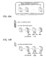
- the determination target image is updated with the third image to search an image that can be deleted (see FIG. 9B ).
- the second to (k-1)-th images can be deleted, and the k-th image cannot be deleted (see FIG.
- the second to (k-1)-th images are sufficiently covered by the first image even if the second to (k-1)-th images are deleted.
- the k-th image that cannot be covered by the first image is set to the next reference image that is allowed to remain in the summary image sequence.
- the method illustrated in FIGS. 9A to 9C reduces the number of summary images by setting the next summary image to be situated away from the preceding summary image as much as possible. However, the method illustrated in FIGS. 9A to 9C determines the k-th image to be the summary image taking account of only the first image, and does not take account of the entire input image sequence including the (k+1)-th to N-th images.
- the object captured within the (k-1)-th image is similar to the object captured within the (k+1)-th to N-th images as compared with the object captured within the k-th image, it may be possible to increase the degree by which the determination target image is covered by the reference image, and reduce the number of images included in the resulting summary image sequence, by setting the (k-1)-th image to be the summary image.
- a method that calculates a globally optimized summary image sequence based on a summarization interval evaluation value G that is an evaluation value when images within a given interval are deleted.
- N is an integer equal to or larger than 2
- the s-th (s is an integer that satisfies 0 ⁇ s ⁇ N+1) image
- the t-th (t is an integer that satisfies 0 ⁇ t ⁇ s-1) image
- a deletion evaluation value when each of the (t+1)-th to (s-1)-th images is set to be the determination target image is calculated from the coverage or the like.
- the summarization interval evaluation value G(t, s) that is the evaluation value when each of the (t+1)-th to (s-1)-th images is deleted, is calculated based on the deletion evaluation value of each of the (t+1)-th to (s-1)-th images, and the image summarization process is performed based on the summarization interval evaluation value.
- the optimum summary image sequence may be determined using dynamic programming.
- An image processing device includes an image sequence acquisition section 200 that acquires an image sequence that includes first to N-th (N is an integer equal to or larger than 2) images as constituent images, and a processing section 100 that performs the image summarization process that deletes some of the first to N-th images included in the image sequence acquired by the image sequence acquisition section 200 to generate a summary image sequence (see FIG. 21 ).
- the processing section 100 selects an s-th (s is an integer that satisfies 0 ⁇ s ⁇ N+1) image included in the input image sequence to be a provisional (temporary or conditional) summary image, selects a t-th (t is an integer that satisfies 0 ⁇ t ⁇ s-1) image included in the input image sequence to be a provisional (temporary or conditional) preceding summary image, selects a u-th (u is an integer that satisfies t ⁇ u ⁇ s) image included in the input image sequence to be the determination target image, calculates the deletion evaluation value of the determination target image based on the deformation information about the provisional summary image and the determination target image, and the deformation information about the provisional preceding summary image and the determination target image, calculates the summarization interval evaluation value G(t, s) that is the evaluation value when the (t+1)-th to (s-1)-th images are deleted based on the deletion evaluation values of the (t+1)-th to (s-
- a first embodiment illustrates a method that performs a process based on the coverage as the process that utilizes the deformation information.
- the summarization interval evaluation value G is calculated based on the number of images included in the interval (i.e., the number of images that can be deleted when the interval is selected), and the coverage.
- a second embodiment illustrates a method that performs the erosion process that utilizes the structural element as the process that utilizes the deformation information.
- the summarization interval evaluation value G is calculated based on the number of images included in the interval (i.e., the number of images that can be deleted when the interval is selected).
- the method according to the first embodiment and the method according to the second embodiment may be combined as a modifications (described later).
- the first embodiment illustrates the method that utilizes the coverage. Dynamic programming will be briefly explained first, and a method that applies dynamic programming to the image summarization process will then be described. A system configuration example of the image processing device will be described thereafter, and the flow of the process will then be described using a flowchart. A specific example of the process according to first embodiment will be described thereafter with reference to FIGS. 5A to 8B , and a modification that takes account of a reduction in the amount of calculations will then be described.
- Dynamic programming is used for various methods (e.g., optimum path search and matching). For example, dynamic programming can be used when calculating the optimum path from the point A to the point B illustrated in FIG. 12 .
- movement from the point A toward the point B occurs in the rightward direction, the upward direction, or the upper right direction, and movement in the backward direction does not occur.
- An evaluation value (e.g., p1 to p12) for movement through each path (route) is set between each node. Note that a larger evaluation value represents a better evaluation result.
- the optimum path from the point A to the point B can be defined to be a path that maximizes the total evaluation value of each branch, for example.
- the problem illustrated in FIG. 12 can be solved by calculating the total evaluation value corresponding to all of the paths from the point A to the point B, and determining the path that provides the maximum total evaluation value to be the optimum path.
- the total number of paths is small, and the total evaluation value can be calculated corresponding to all of the paths.
- the problem is a large-scale problem (e.g., the number of nodes is several tens of thousands when implementing the image summarization process), it is not realistic to integrate the evaluation values corresponding to all of the paths.
- Dynamic programming makes it possible to solve such a problem with a realistic amount of calculations. Specifically, the evaluation value (i.e., the largest value among the candidates for the evaluation value) of each node, and the node that precedes each node are determined from the node closest to the point A instead of directly calculating the evaluation value at the point B. The evaluation value of the next node is determined utilizing the evaluation value of each node that has been calculated.
- FIG. 12 illustrates a specific example of this process. Since the number of paths from the point A to the point N1 is one, the evaluation value E(N1) of the point N1 is calculated to be p1. Likewise, the evaluation value E(N2) of the point N2 is calculated to be p2.
- the advantage of dynamic programming is small when calculating the evaluation value of the point N3.
- dynamic programming has a significant advantage as the distance from the start point (point A) to the evaluation value calculation target node increases. For example, when calculating all of the paths from the point A to the point N5, it is necessary to calculate the candidates for the evaluation value corresponding to five paths, and compare the calculated values.
- the evaluation value E(N5) can be determined by calculating the largest value among the values E(N1)+p9, E(N4)+p7, and E(N3)+p8.
- the evaluation value EB of the point B can be determined by performing the above process from the point A toward the point B, and calculating the largest value among the values E(N8)+p12, E(N9)+p10, and E(N10)+p11. Therefore, the amount of calculations can be significantly reduced as compared with the case of directly calculating the evaluation value corresponding to all of the paths from the point A to the point B.
- the optimum path is determined by tracing each preceding point from the point B in reverse order.
- one of the points N8 to N10 has been determined to be the optimum point (i.e., a point that maximizes the evaluation value EB) that immediately precedes the point B when calculating the evaluation value EB.
- the path from the point N8 to the point B is determined to be part of the optimum path.
- One of the points N5 to N7 has been determined to be the optimum point (i.e., a point that maximizes the evaluation value E(N8)) that immediately precedes the point N8.
- the path from the point N5 to the point B through the point N8 is determined to be part of the optimum path.
- the path from the point B to the point A through each optimum preceding point corresponds to the optimum path (in reverse order).
- each image included in the input image sequence is considered to be each node of a path, and a path that passes through only the images that are allowed to remain in the summary image sequence is determined by performing the process on the first image to the last image included in the input image sequence.
- the image summarization process is considered to be a problem that searches the optimum path.
- a path "1-2-3-4-5" is the optimum path when all of the images are allowed to remain in the summary image sequence
- a path "2-4" is the optimum path when only the second image and the fourth image are allowed to remain in the summary image sequence.
- the method according to the first embodiment sets a virtual zero-th image and a virtual (N+1)-th image when the input image sequence includes N images, wherein the zero-th image is set to be the start point (i.e., the point A illustrated in FIG. 12 ), and the (N+1)-th image is set to be the end point (i.e., the point B illustrated in FIG. 12 ).
- the summarization interval evaluation value G calculated using the deformation information about images is used as the evaluation value between the nodes.
- the summarization interval evaluation value G(2, 4) calculated on the assumption that the second image and the fourth image are allowed to remain in the summary image sequence, and the third image is deleted, may be used as the evaluation value of the branch between a node 2 and a node 4.
- FIG. 1 illustrates a system configuration example of the image processing device according to the first embodiment.
- the image processing device includes a processing section 100, an image sequence acquisition section 200, and a storage section 300.
- the processing section 100 performs the image summarization process that deletes some of a plurality of images included in an image sequence acquired by the image sequence acquisition section 200.
- the function of the processing section 100 may be implemented by hardware such as a processor (e.g., CPU) or an ASIC (e.g., gate array), a program, or the like.
- the image sequence acquisition section 200 acquires the image sequence that is subjected to the image summarization process.
- the image sequence acquired by the image sequence acquisition section 200 may include RGB channel images that are arranged in time series.
- the image sequence acquired by the image sequence acquisition section 200 may be a spatially continuous image sequence (e.g., an image sequence that includes spatially arranged images that have been captured using imaging devices arranged in a row). Note that the images included in the image sequence are not limited to RGB channel images. Another color space (e.g., Gray channel image) may also be used.
- the storage section 300 stores the image sequence acquired by the image sequence acquisition section 200, and serves as a work area for the processing section 100 and the like.
- the function of the storage section 300 may be implemented by a memory (e.g., RAM), a hard disk drive (HDD), or the like.
- the processing section 100 may include a deformation estimation section 1001, a provisional summary image selection section 1002, a provisional preceding summary image selection section 1003, a determination target image selection section 1004, a coverage calculation section 1005, a summarization interval evaluation value calculation section 1006, a provisional total evaluation value calculation section 1007, an optimum preceding summary image determination section 1008, a total evaluation value update section 1009, and a summary image sequence determination section 1010 (see FIG. 1 ).
- the configuration of the processing section 100 is not limited to the configuration illustrated in FIG. 1 . Various modifications may be made, such as omitting some of the elements illustrated in FIG. 1 , or adding other elements.
- each section illustrated in FIG. 1 is provided in order to describe each subroutine when the image summarization process performed by the processing section 100 is divided into a plurality of subroutines.
- the processing section 100 does not necessarily include each section illustrated in FIG. 1 as an element.
- the deformation estimation section 1001 performs a deformation estimation process on two images to acquire the deformation information.
- the deformation information represents a shape (range) in which the range captured within one image is captured within the other image.
- the deformation information may be the deformation parameter disclosed in Patent Document 2, for example.
- the deformation estimation section 1001 acquires the deformation information about the provisional summary image selected by the provisional summary image selection section 1002 and the determination target image selected by the determination target image selection section 1004, and the deformation information about the provisional preceding summary image selected by the provisional preceding summary image selection section 1003 and the determination target image, and calculates the coverage based on the acquired deformation information.
- the deformation estimation section 1001 need not necessarily directly calculate the deformation information about the reference image (i.e., provisional summary image or provisional preceding summary image) and the determination target image.
- the deformation information about contiguous images included in the processing target image sequence may be calculated, and the deformation information about non-contiguous images may be calculated by combining the deformation information about contiguous images.
- the deformation information about the reference image and the determination target image is calculated by combining the deformation information (all pieces of deformation information in a narrow sense) about the reference image, the determination target image, and contiguous images between the reference image and the determination target image.
- the deformation information can be calculated using the method disclosed in Patent Document 2, for example.
- the processing load is normally very light when combining a plurality of pieces of deformation information as compared with the case of calculating the deformation information from the beginning.
- the processing load is heavy when calculating the matrix from two pieces of image information, while it is very easy to synthesize a plurality of matrices calculated in advance (since it suffices to calculate the product of the matrices, for example).
- the image sequence acquired by the image sequence acquisition section 200 includes N images
- two images can be selected from the image sequence in N ⁇ (N-1)/2 combinations. Therefore, when directly calculating the deformation information about the reference image and the determination target image, the heavy-load process that calculates the deformation information from the beginning may be performed N 2 times. On the other hand, it suffices to perform the heavy-load process only N-1 times when using the deformation information about contiguous images.
- the provisional summary image selection section 1002 selects an image in time series from an image (zero-th image) that is virtually arranged to precede the first image of the image sequence to an image ((N+1)-th image) that is virtually arranged to immediately follow the last image of the image sequence, and sets the selected image to be the provisional summary image.
- the provisional summary image is an image for which the total evaluation value E is calculated.
- the provisional preceding summary image selection section 1003 selects the provisional preceding summary image.
- the provisional preceding summary image is an image that immediately precedes the provisional summary image, and is a candidate for the summary image.
- a candidate for the total evaluation value of the provisional summary image can be calculated from the total evaluation value E of the provisional preceding summary image, and the summarization interval evaluation value between the provisional preceding summary image and the provisional summary image.
- the (k-1)-th image is allowed to remain in the summary image sequence, or the (k-1)-th image is deleted, and the (k-2)-th image is allowed to remain in the summary image sequence, or the (k-1)-th image and the (k-2)-th image are deleted, and the (k-3)-th image is allowed to remain in the summary image sequence, or all of the first to (k-1)-th images are deleted.
- all of the images from the image that immediately precedes the provisional summary image to the zero-th image may be sequentially selected as the provisional preceding summary image when it is desired to take account of each case.
- the process may be terminated without setting an image that is situated further away from the provisional summary image to be the provisional preceding summary image (as described later). Therefore, the provisional preceding summary image selection section 1003 selects the image that immediately precedes the provisional summary image to be the first provisional preceding summary image, and sequentially updates the provisional preceding summary image with the image that immediately precedes the current provisional preceding summary image, taking account of the processing efficiency.
- the determination target image selection section 1004 sequentially selects the images between the provisional summary image and the provisional preceding summary image to be the determination target image.
- the determination target image selection section 1004 selects the image that immediately precedes the provisional summary image to be the first determination target image, and sequentially updates the determination target image from (with) the image that immediately precedes the current determination target image until the image that immediately follows the provisional preceding summary image is reached.
- the coverage calculation section 1005 calculates the coverage of the determination target image based on first deformation information about the provisional summary image and the determination target image, and second deformation information about the provisional preceding summary image and the determination target image.
- FIGS. 2 and 3 illustrate an example of the coverage calculation process.
- the provisional summary image is deformed using the first deformation information, and projected onto the determination target image to calculate a first coverage area.
- the provisional preceding summary image is deformed using the second deformation information, and projected onto the determination target image to calculate a second coverage area.
- the sum area of the first coverage area and the second coverage area i.e., an area that is included in at least one of the first coverage area and the second coverage area
- the ratio of the coverage area to the determination target image i.e., the area ratio of the coverage area to the determination target image in a narrow sense) is used as the coverage.
- the summarization interval evaluation value is calculated using the coverage.
- the coverage of at least one determination target image is less than the threshold value k1
- the degree of coverage of the image between the provisional summary image and provisional preceding summary image is very low. In this case, it is considered that it is not likely that the image between the provisional summary image and provisional preceding summary image can be covered even if the provisional preceding summary image is updated with the image that is situated further away from the provisional summary image. In such a case, not only the determination target image update process, but also the provisional preceding summary image update process may be terminated, and the provisional summary image update process may be performed. The details of this branching process is described later with reference to FIG. 4 (flowchart).
- the summarization interval evaluation value calculation section 1006 calculates the summarization interval evaluation value based on the coverage, and the number of images between the provisional preceding summary image and the provisional summary image. This is because it is considered that an appropriate summary image sequence can be obtained when the number of images that can be deleted is large, and the coverage is high (see above). Specifically, a first evaluation value is calculated from the total coverage of the determination target images, and the number of images between the provisional preceding summary image and the provisional summary image is calculated to be a second evaluation value. The weighted sum of the first evaluation value and the second evaluation value is then calculated to calculate the summarization interval evaluation value.
- the weight (total number of images included in image sequence) is large, it is possible to determine the optimum summary image sequence while attaching importance to the number of images that are deleted. Note that the summarization interval evaluation value calculation method is not limited thereto.
- the provisional total evaluation value calculation section 1007 calculates the provisional total evaluation value (i.e., a value that is a candidate for the total evaluation value) of the provisional summary image. Specifically, the sum of the total evaluation value of the provisional preceding summary image, and the summarization interval evaluation value calculated corresponding to the provisional summary image and the provisional preceding summary image, is used as the provisional total evaluation value. Since the total evaluation value of the zero-th image is 0, the provisional total evaluation value is equal to the summarization interval evaluation value when the provisional preceding summary image is the zero-th image.
- the optimum preceding summary image determination section 1008 determines the provisional preceding summary image that gives the optimum provisional total evaluation value (i.e., the largest provisional total evaluation value in a narrow sense) among one or more provisional total evaluation values calculated by the provisional total evaluation value calculation section 1007, to be the optimum preceding summary image.
- the total evaluation value update section 1009 determines the optimum provisional total evaluation value (i.e., the largest provisional total evaluation value in a narrow sense) to be the total evaluation value of the provisional summary image.
- the summary image sequence determination section 1010 sets the summary image sequence by tracing the optimum preceding summary images after the total evaluation value E(N+1) of the (N+1)-th image has been calculated. Specifically, when the (N+1)-th image is the first processing target image, and the optimum preceding summary image that precedes the processing target image is not the zero-th image, the optimum preceding summary image is allowed to remain in the summary image sequence, and set to be the next processing target image. When the optimum preceding summary image is the zero-th image, the summary image sequence determination process is terminated. This makes it possible to implement the process that traces the optimum preceding summary image from the (N+1)-th image to the zero-th image to generate a summary image sequence that includes the images (nodes) that form the path.
- the deformation estimation process is performed in the step S101.
- the deformation estimation process acquires the deformation information about contiguous images included in the input image sequence.
- the provisional summary image is then selected (S102).
- the zero-th image i.e., virtual image
- the provisional summary image is updated with the image that immediately follows the current provisional summary image within the input image sequence.
- the provisional preceding summary image is selected (S103). Specifically, the image that immediately precedes the provisional summary image is selected to be the provisional preceding summary image.
- the provisional preceding summary image is updated with the image that immediately precedes the current provisional preceding summary image.
- the images between the provisional summary image and the provisional preceding summary image are sequentially selected to be the determination target image (S104).
- the coverage is calculated using the first deformation information about the provisional summary image and the determination target image, and the second deformation information about the provisional preceding summary image and the determination target image (S105).
- the first deformation information and the second deformation information may be calculated using the results of the deformation estimation process performed in the step S101.
- the determination target image is updated in the step S104.
- the steps S104 and S105 are repeated as long as the determination target image can be deleted, and the process is performed on all of the images between the provisional summary image and the provisional preceding summary image.
- the summarization interval evaluation value is calculated (S106), and the provisional total evaluation value of the provisional summary image is calculated based on the summarization interval evaluation value and the total evaluation value of the provisional preceding summary image (S107).
- the provisional preceding summary image is then updated in the step S102.
- the summarization interval evaluation value is set to a sufficiently small value (e.g., - ⁇ ) so that the current combination of the provisional summary image and the provisional preceding summary image is not employed as the summary image.
- the coverage is a moderate value, and it has not been determined to terminate the process, the provisional preceding summary image is updated in the step S103.
- the degree of coverage of the images between the provisional summary image and the provisional preceding summary image may increase depending on the object and the like as the number of images between the provisional summary image and the provisional preceding summary image increases.
- the coverage of the determination target image is very small (e.g., when the coverage is less than k2)
- the summarization interval evaluation value of the image that is included in the search interval of the provisional preceding summary image, and has not been selected to be the provisional preceding summary image in the step S103 may be set to a sufficiently small value, taking account of the process performed in the step S108 and subsequent step. For example, when it has been scheduled to select the (k-1)-th image to the zero-th image to be the provisional preceding summary image, but it has been determined to terminate the process when the (k-z)-th image has been selected, the summarization interval evaluation value is not set when the (k-z-1)-th image to the zero-th image are selected to be the provisional preceding summary image. Therefore, the summarization interval evaluation value may be set to - ⁇ .
- This state refers to a state in which all of the images including the image that immediately precedes the provisional summary image to the zero-th image have been selected to be the provisional preceding summary image, and the process has been performed, for example.
- the above state refers to a state in which ⁇ images have been selected to be the provisional preceding summary image sequentially from the image that immediately precedes the provisional summary image, and the process has been performed.
- the provisional total evaluation value (i.e., the total evaluation value when one more provisional preceding summary image or each of a plurality of provisional preceding summary images has been set to be the preceding summary image with respect to the provisional summary image selected in the step S102) has been calculated when the step S108 is performed. Therefore, the provisional preceding summary image that gives the optimum provisional total evaluation value (i.e., the largest provisional total evaluation value in a narrow sense) is determined to be the optimum preceding summary image (S108), and the evaluation value is determined to be the total evaluation value of the provisional summary image (S109).
- the total evaluation value of the provisional summary image selected in the S102 can be calculated by appropriately repeating the steps S103 to S109.
- the provisional summary image is updated (S102) after the step S109, and the steps S103 to S109 are repeated to calculate the total evaluation value corresponding to all of the zero-th to (N+1)-th images.
- the summary image sequence determination process (S110) is performed. Specifically, a path is selected that starts from the (N+1)-th image, and sequentially traces the optimum preceding summary image that precedes the processing target image up to the zero-th image.
- the process according to the first embodiment determines the image sequence that includes the images along the path (excluding the zero-th image and the (N+1)-th image (virtual images)) to be the summary image sequence.
- FIGS. 5A to 8B A specific example of the process according to the first embodiment is described below with reference to FIGS. 5A to 8B .
- the following description illustrates an example in which an image sequence that includes first to sixth images has been input.
- the numerals 0 to 7 in the lower part of FIGS. 5A to 8B represent the constituent images included in the input image sequence, and the numeral(s) under each of the numerals 0 to 7 represent(s) the total evaluation value of the corresponding image.
- the value assigned to each intersection of the lattice illustrated in FIGS. 5A to 8B represents the summarization interval evaluation value between two images respectively situated at the lower right and the lower left of the intersection.
- the thick straight line represents a path from the provisional summary image to the zero-th image through the optimum preceding summary image(s).
- the total evaluation value E(0) of the zero-th image is 0.
- the first image is selected to be the provisional summary image
- the image that precedes the first image is selected to be the provisional preceding summary image.
- the zero-th image is selected to be the provisional preceding summary image
- the summarization interval evaluation value G(0, 1) between the zero-th image and the first image is calculated.
- the provisional summary image is updated with the second image.
- the first image is selected to be the provisional preceding summary image, and the summarization interval evaluation value G(1, 2) is calculated.
- the zero-th image is selected to be the provisional preceding summary image, and the summarization interval evaluation value G(0, 2) is calculated.
- the first image is selected to be the determination target image when calculating the summarization interval evaluation value G(0, 2).
- the provisional total evaluation values "E(1)+G(1, 2)" and “E(0)+G(0, 2)" are calculated, the optimum provisional total evaluation value is determined to be the total evaluation value E(2), and the provisional preceding summary image that gives the optimum provisional total evaluation value is determined to be the optimum preceding summary image.
- the total evaluation value E(2) is 1093, and the zero-th image is determined to be the optimum preceding summary image.
- the third image has been selected to be the provisional summary image
- the second to zero-th images are sequentially selected to be the provisional preceding summary image.
- the one image is selected to be the determination target image, or the plurality of images are sequentially selected to be the determination target image, and the coverage is calculated to calculate the summarization interval evaluation value G. Since the provisional total evaluation values are calculated in a number (three in FIG.
- the optimum provisional total evaluation value is determined to the total evaluation value E(3), and the zero-th image that gives the optimum provisional total evaluation value is determined to be the optimum preceding summary image.
- FIGS. 7A to 8A also applies to FIGS. 7A to 8A .
- the summarization interval evaluation value G(0, 4) is - ⁇ . Since the optimum preceding summary image is not the zero-th image, it is possible to further determine the optimum preceding summary image.
- the total evaluation value (E(7) in FIG. 8B ) of the virtual image that is set to follow the last image of the input image sequence is calculated. Since the optimum preceding summary image that precedes the seventh image is the fifth image, the optimum preceding summary image that precedes the fifth image is the second image, and the optimum preceding summary image that precedes the second image is the zero-th image, the optimum path from the zero-th image to the seventh the image is calculated to be "0-2-5-7" (see FIG. 8B ). Since the zero-th image and the seventh image are virtual images, the optimum summary image sequence of the input image sequence that includes the first to sixth images is determined to be an image sequence that includes the second image and the fifth image.
- the process described above with reference to FIG. 4 uses the input image sequence as the image sequence subjected to the image summarization process.
- the processing time of dynamic programming increases in proportion to the second power of the processing interval length (e.g., a value determined by the path length (determined by the number of images included in the input image sequence in the first embodiment)).
- the number of images included in the image sequence that is subjected to the image summarization process is very large, it may be difficult to calculate the optimal solution within a realistic processing time even if dynamic programming is used.
- the image sequence may be divided into a plurality of partial image sequences, and the above process may be performed using each partial image sequence as the input image sequence. This makes it possible to reduce the processing interval length, and reduce the entire processing time.
- a scene change may be detected from the image sequence, and the image sequence may be divided into a plurality of partial image sequences based on the detected scene change.
- a scene change may be detected using various methods.
- a deformation estimation process may be performed using the method disclosed in Patent Document 2, it may be determined that the deformation estimation process has failed when the area of a region (i.e., the number of pixels of a mask image that represents the region) that can be accurately subjected to registration is equal to or less than a given threshold value, and it may be determined that a scene change has occurred between the contiguous images for which the deformation estimation process has failed.
- four partial image sequences B1 to B4 may be set to be divided at the scene changes A1 to A3.
- the plurality of partial image sequences need not necessarily be sequentially processed one by one.
- the configuration of the processing section 100 is suitable for parallel processing (e.g., when a CPU that includes a plurality of cores is used as the processing section 100), or when the image processing device according to the first embodiment is implemented by a plurality of computers, and distributed processing is performed by each computer, the image summarization process may be performed on the plurality of partial image sequences in parallel. This makes it possible to reduce the time required for the image summarization process, for example.
- the image processing device includes the image sequence acquisition section 200 that acquires an input image sequence that includes first to N-th (N is an integer equal to or larger than 2) images as constituent images, and the processing section 100 that performs the image summarization process that deletes some of the first to N-th images included in the input image sequence acquired by the image sequence acquisition section 200 to generate a summary image sequence (see FIG. 1 or 21 ).
- the processing section 100 selects an s-th (s is an integer that satisfies 0 ⁇ s ⁇ N+1) image included in the input image sequence to be the provisional summary image, selects a t-th (t is an integer that satisfies 0 ⁇ t ⁇ s-1) image included in the input image sequence to be the provisional preceding summary image, and selects a u-th (u is an integer that satisfies t ⁇ u ⁇ s) image included in the input image sequence to be the determination target image.
- the processing section 100 calculates the deletion evaluation value of the determination target image based on the deformation information about the provisional summary image and the determination target image, and the deformation information about the provisional preceding summary image and the determination target image, calculates the summarization interval evaluation value G(t, s) that is the evaluation value when the (t+1)-th to (s-1)-th images are deleted based on the deletion evaluation values of the (t+1)-th to (s-1)-th images, and performs the image summarization process based on the summarization interval evaluation value.
- the summarization interval evaluation value G(t, s) is the evaluation value when the t-th image and the s-th image are allowed to remain in the summary image sequence, and all of the (t+1)-th to (s-1)-th images are deleted. Specifically, when an a-th image , a b-th image, and a c-th image are allowed to remain in the summary image sequence, the evaluation value of the summary image sequence can be calculated from the summarization interval evaluation value G(a, b) and the summarization interval evaluation value G(b, c).
- the summarization interval evaluation value G(0, a) and the summarization interval evaluation value G(c, N+1) are also used when the zero-th image and the (N+1)-th image are provided as virtual images. Therefore, it is possible to calculate the evaluation value of an arbitrary summary image sequence generated from the input image sequence by calculating all of the summarization interval evaluation values between two arbitrary images among the first to N-th images, and find (search) the optimum summary image sequence from a plurality of candidates for the summary image sequence.
- the summarization interval evaluation value G may be calculated corresponding to all of the combinations of two images among the first to N-th images (or the zero-th to (N+1)-th images (including the virtual images)).
- summarization interval evaluation values G may not be calculated from the viewpoint of reducing the amount of calculations. Since the summarization interval evaluation value is calculated based on the deformation information about images, it is possible to control the degree by which an area that cannot be observed occurs due to deletion of an image.
- the processing section 100 may calculate the total evaluation values E(1) to E(N) of the first to N-th images based on the summarization interval evaluation value, and perform the image summarization process based on the total evaluation values.
- the total evaluation value E(k) represents the optimum evaluation value among the evaluation values on the assumption that the zero-th image and the k-th image are allowed to remain in the summary image sequence. Note that the (k+1)-th to (N+1)-th images are not taken into consideration. When allowing the zero-th image and the k-th image to remain in the summary image sequence, each of the first to (k-1)-th images is either allowed to remain in the summary image sequence, or deleted. Therefore, the total evaluation value E(k) represents the optimum combination (or the combination that has been determined to be optimum) among 2 k-1 combinations.
- the optimum combination as to whether or not to delete the first to (k-1)-th images on the assumption that the k-th image is allowed to remain in the summary image sequence by calculating the total evaluation value E(k).
- the optimum combination as to whether or not delete the first to N-th images can be determined by calculating the total evaluation value E(N+1) of the (N+1)-th image (virtual image).
- This process is a process that globally calculates the optimum summary image sequence.
- the first embodiment may utilize dynamic programming in order to reduce the amount of calculations.
- the first embodiment implements the image summarization process by calculating the total evaluation values E(1) to E(N) of the first to N-th images.
- the total evaluation value E(v) can be calculated by calculating "E+G" v times, and calculating the optimum value (i.e., the largest value in a narrow sense) without taking account of all of the combinations as to whether or not to delete the zero-th to v-th images. Specifically, it is possible to significantly reduce the amount of calculations as compared with the case of directly calculating the total evaluation value E(N+1) (although it is necessary to calculate the total evaluation values E(1) to E(N)).
- the processing section 100 may select an x-th image that satisfies the following expression (1) to be the optimum preceding summary image that precedes the v-th image.
- x arg max w ⁇ E w + G w v
- the processing section 100 may calculate the total evaluation value E(N+1) of the (N+1)-th image that is a virtual image, and set the (N+1)-th image to be the first processing target image during the summary image sequence determination process.
- the processing section 100 may allow the optimum preceding summary image to remain in the summary image sequence, update the processing target image with the optimum preceding summary image, and continue the summary image sequence determination process, when the optimum preceding summary image that precedes the processing target image is not the zero-th image.
- the processing section 100 may terminate the summary image sequence determination process when the optimum preceding summary image that precedes the processing target image is the zero-th image.
- the optimum preceding summary image that precedes the v-th image when calculating the total evaluation value E(v), and perform the summary image sequence determination process using the optimum preceding summary image.
- the optimum path can be determined by determining the preceding node that immediately precedes each node, and sequentially tracing the preceding nodes from the end point. In the first embodiment, this process is applied to an image sequence.
- the provisional preceding summary image that maximizes the provisional total evaluation value of the provisional summary image is determined to be the optimum preceding summary image.
- the summary image sequence determination process traces the optimum preceding summary images from the (N+1)-th image to the zero-th image.
- the processing section 100 may calculate the coverage of the u-th image based on the deformation information about the s-th image and the u-th image, and the deformation information about the t-th image and the u-th image, the coverage of the u-th image being the ratio in which the u-th image is covered by the s-th image and the t-th image.
- the processing section 100 may calculate the deletion evaluation value based on the coverage, and calculate a value obtained by adding up the deletion evaluation values of the (t+1)-th to (s-1)-th images to be the summarization interval evaluation value G(t, s) when the (t+1)-th to (s-1)-th images are deleted.
- the coverage may be calculated using the coverage area (see FIGS. 2 and 3 ), or may be calculated using another method.
- the coverage since the coverage is used to calculate the summarization interval evaluation value, it is expected that the summary image sequence determined based on the summarization interval evaluation value has a high coverage (i.e., a summary image sequence for which occurrence of an area that cannot be observed is suppressed).
- the processing section 100 may determine whether or not the u-th image can be deleted based on the deformation information about the s-th image and the u-th image, and the deformation information about the t-th image and the u-th image.
- the processing section 100 may set a first value to be the summarization interval evaluation value G(t, s) when the (t+1)-th to (s-1)-th images are deleted, when it has been determined that at least one constituent image among the (t+1)-th to (s-1)-th images cannot be deleted.
- the processing section 100 may set the first value to negative infinity, or a value that is equal to or smaller than a given threshold value determined based on the total evaluation value.
- a value that prevents a situation in which the t-th image is selected to be the optimum preceding summary image that precedes the s-th image is set to be the evaluation value of the summary image sequence.
- the provisional total evaluation value calculated using the summarization interval evaluation value that is the first value is necessarily smaller than the provisional total evaluation value calculated using the summarization interval evaluation value that is a value other than the first value (corresponding to the case where all of the (t+1)-th to (s-1)-th images can be deleted) when - ⁇ is used as the first value.
- the first value need not necessarily be - ⁇ as long as the relation ship "(largest provisional total evaluation value when image cannot be deleted) ⁇ (smallest provisional total evaluation value when image can be deleted)" is satisfied.
- the first value is determined based on the total evaluation value since the provisional total evaluation value is determined by the total evaluation value of the provisional preceding summary image and the summarization interval evaluation value.
- the first value may be a negative value of which the absolute value is large to such an extent that the order differs to a large extent from a value that is considered to be the total evaluation value.
- the first value may be a value that is smaller than the value "(minimum value that may be used as total evaluation value of provisional summary image)-(total evaluation value of provisional preceding summary image).
- the condition whereby the t-th image is not selected to be the optimum preceding summary image that precedes the s-th image, is also satisfied.
- the processing section 100 may calculate the summarization interval evaluation value G(t, s) when the (t+1)-th to (s-1)-th images are deleted, based on the number of the (t+1)-th to (s-1)-th images, when it has been determined that all of the (t+1)-th to (s-1)-th images can be deleted.
- the processing section 100 may set the first value to be the summarization interval evaluation value G(x, s) when the constituent image between an x-th (x is an integer that satisfies 0 ⁇ x ⁇ t) image and the s-th image is deleted, and terminate the process in which the s-th image is selected to be the provisional summary image.
- the first value may be set to be the summarization interval evaluation value when the zero-th to (t-1)-th images are selected to be the provisional preceding summary image.
- the processing section 100 may select (s- ⁇ )-th ( ⁇ is a positive integer) to (s-1)-th images among the zero-th to (s-1)-th images to be the provisional preceding summary image.
- the input image sequence used in connection with the first embodiment has a tendency in which it is unlikely that the images between the provisional summary image and the provisional preceding summary image can be covered when the number of images between the provisional summary image and the provisional preceding summary image is too large.
- the provisional preceding summary image is set at a position significantly away from the provisional summary image, it is unlikely that the provisional preceding summary image is determined to be the optimum preceding summary image, and it may not be useful to perform the process on such a provisional preceding summary image. Therefore, the provisional preceding summary image setting range may be limited.
- the processing section 100 may detect a scene change from the input image sequence, set constituent images among the plurality of constituent images included in the input image sequence that follow an i-th (i is an integer) scene change and precede an (i+1)-th scene change, to be a partial image sequence, when the i-th scene change and the (i+1)-th scene change that follows the i-th scene change have been detected from the input image sequence, and perform the image summarization process on the partial image sequence.
- the processing time of dynamic programming is proportional to the second power of the processing interval length. It is possible to reduce the processing time by performing the process on each partial image sequence. The processing time may be further reduced by performing the process on a plurality of partial image sequences in parallel.
- the image processing device and the like according to the first embodiment are implemented by causing a processor (e.g., CPU) to execute a program.
- a processor e.g., CPU
- a program stored in a non-transitory information storage device is read, and executed by a processor (e.g., CPU).
- the information storage device (computer-readable device) stores a program, data, and the like.
- the function of the information storage device may be implemented by an optical disk (e.g., DVD or CD), a hard disk drive (HDD), a memory (e.g., memory card or ROM), or the like.
- the processor e.g., CPU performs various processes according to the first embodiment based on the program (data) stored in the information storage device.
- a program that causes a computer i.e., a device that includes an operation section, a processing section, a storage section, and an output section
- a program that causes a computer to execute the process implemented by each section is stored in the information storage device.
- the image processing device and the like according to the first embodiment may include a processor and a memory.
- the processor may be a central processing unit (CPU), for example. Note that the processor is not limited to a CPU. Various other processors such as a graphics processing unit (GPU) or a digital signal processor (DSP) may also be used.
- the processor may be a hardware circuit that includes an ASIC.
- the memory stores computer-readable instructions. Each section of the endoscope apparatus and the like according to the first embodiment is implemented by causing the processor to execute the instructions.
- the memory may be a semiconductor memory (e.g., SRAM or DRAM), a register, a hard disk, or the like.
- the instructions may be instructions included in an instruction set that forms a program, or may be instructions that cause a hardware circuit of the processor to operate.
- a method that determines the probability that the attention area is missed based on the erosion process that utilizes the structural element is described below.
- FIG. 13 illustrates a configuration example of the image processing device according to the second embodiment.
- the image processing device according to the second embodiment differs from the image processing device according to the first embodiment (see FIG. 1 ) in that the coverage calculation section 1005 is omitted, and an attention area miss determination section 1011 is additionally provided.
- the remaining sections are the same as described above in connection with the first embodiment, except for the way in which the summarization interval evaluation value calculation section 1006 calculates the summarization interval evaluation value G, and detailed description of each section is appropriately omitted.
- the attention area miss determination section 1011 performs a determination process that determines the probability that the attention area captured within the determination target image is not captured within the provisional summary image and the provisional preceding summary image (i.e., the attention area is missed) when the determination target image is deleted.
- the attention area miss determination section 1011 generates the structural element based on the attention area (e.g., a lesion that should not be missed when using a capsule endoscope).
- the attention area miss determination section 1011 sets an area having a size and a shape that should not be missed to be the structural element taking account of a typical size and the like of the attention area. For example, when the attention area is a lesion, and a lesion that is larger than a circle having a diameter of 30 pixels within the image is severe, and should not be missed, a circle having a diameter of 30 pixels is set to be the structural element.
- first deformation information about the provisional summary image and the determination target image, and second deformation information about the provisional preceding summary image and the determination target image are acquired using the results of the deformation estimation process performed by the deformation estimation section 1001.
- the provisional summary image and the provisional preceding summary image are projected onto the determination target image by utilizing the acquired deformation information to calculate the coverage area in the same manner as in the first embodiment.
- the attention area miss determination section 1011 determines the probability that the attention area is missed. Specifically, the attention area miss determination section 1011 performs the erosion process that utilizes the structural element on the non-coverage area (i.e., an area other than the coverage area) of the determination target image to determine whether or not a residual area is present (see FIG. 14 ).
- the non-coverage area is necessarily a closed area, and the boundary of the non-coverage area can be set.
- an outer boundary BO1 and an inner boundary BO2 are set in FIG. 15A .
- the erosion process that utilizes the structural element removes the overlapping area of the non-coverage area and the structural element when a reference point of the structural element is set at the boundary of the non-coverage area.
- a circular area is set to be the structural element, and the reference point of the structural element is the center of the circle
- the erosion process draws a circle so that the center of the circle is situated at the boundary of the non-coverage area, and excludes the overlapping area of the circle and the non-coverage area from the non-coverage area.
- a circle is drawn around a point situated at the outer boundary BO1 of the non-coverage area (see FIG. 15A ), and the overlapping area of the circle and the non-coverage area (i.e., the semicircular area indicated by the diagonal lines in FIG. 15A ) is excluded from the non-coverage area.
- the above process may be performed on each point among the plurality of points. For example, a circle may be sequentially drawn around each point situated at the outer boundary BO1 in a given direction (see FIG. 15A ), and the overlapping area of each circle and the non-coverage area may be excluded from the non-coverage area.
- the non-coverage area may have only a single boundary. In such a case, the above process may be performed on the single boundary.
- the non-coverage area has the outer boundary BO1 and the inner boundary BO2 (see FIG. 15A )
- the above process is performed on the outer boundary BO1 and the inner boundary BO2.
- a circle is drawn around each point situated at the inner boundary BO2 (see FIG. 15B ), and the overlapping area of each circle and the non-coverage area is excluded from the non-coverage area.
- the non-coverage area is reduced as a result of the erosion process.
- the left part of the non-coverage area illustrated in FIG. 15A is completely deleted (i.e., no residual area is present) by the erosion process performed on the outer boundary BO1 (see FIG. 15A ) and the erosion process performed on the inner boundary BO2 (see FIG. 15B ).
- a residual area RE that is not excluded by the erosion process performed on the outer boundary BO1 and the erosion process performed on the inner boundary BO2 occurs in the lower right part of the non-coverage area (see FIG. 15C ).
- only the residual area RE remains as a result of performing the erosion process that utilizes the structural element over the entire non-coverage area (see FIG. 15D ).
- the non-coverage area i.e., closed area
- the non-coverage area is considered to be an area that is surrounded by a boundary (different boundaries (e.g., BO1 and BO2) or a single boundary).
- a boundary different boundaries (e.g., BO1 and BO2) or a single boundary).
- a circle having a radius r that is drawn around an arbitrary point within the residual area does not intersect each boundary. This means that the entirety of the attention area represented by a circle having a radius r that is drawn around a point within the residual area is included within the non-coverage area. Note that the above basic idea is also applied even when the structural element has a shape (e.g., quadrangle) other than a circle.
- the attention area miss determination section 1011 performs the erosion process that utilizes the structural element on the non-coverage area, and determines whether or not the determination target image can be deleted based on whether or not the residual area is present.
- the summarization interval evaluation value calculation section 1006 calculates the summarization interval evaluation value based on the results of the above deletion determination process. Specifically, when it has been determined that all of the images between the provisional summary image and the provisional preceding summary image can be deleted, the summarization interval evaluation value calculation section 1006 sets the number of images that can be deleted (i.e., the number of images included in the summarization interval) to be the summarization interval evaluation value. When it has been determined that at least one of the images between the provisional summary image and the provisional preceding summary image cannot be deleted, the summarization interval evaluation value calculation section 1006 sets a sufficiently small value (e.g., - ⁇ ) to be the summarization interval evaluation value.
- a sufficiently small value e.g., - ⁇
- step S204 the probability that the attention area is missed is determined as described above with reference to FIGS. 15A to 15E .
- the step S204 is performed.
- a sufficiently small value is set to be the summarization interval evaluation value, and the provisional preceding summary image is updated in the step S203.
- the number of images between the provisional summary image and the provisional preceding summary image is calculated to be the summarization interval evaluation value (S206).
- the subsequent steps S207 to S210 are respectively the same as the steps S107 to S210 illustrated in FIG. 4 , and detailed description thereof is omitted.
- the target of the erosion process that utilizes the structural element is not limited to the non-coverage area.
- the erosion process that utilizes the structural element may be performed on the determination target image (see FIG. 17A ).
- a coverage-requiring area that must be covered by the reference image remains (see FIG. 17B ) by setting the structural element so that the entirety of the attention area is not included within the area that is removed by the erosion process (e.g., setting an element having a size twice that of the attention area as the structural element).
- whether or not the determination target image can be deleted may be determined based on whether or not the entirety of the coverage-requiring area is covered by at least one of the provisional summary image and the provisional preceding summary image.
- the provisional summary image and the provisional preceding summary image may be deformed using the deformation information to calculate the coverage area, and the inclusion determination process may be performed using the coverage area and the coverage-requiring area (see FIG. 18 ).
- the determination target image can be deleted when the coverage-requiring area is included within the coverage area, and cannot be deleted when the entirety of the coverage-requiring area is not included within the coverage area.
- the deletion determination process that utilizes the structural element is not limited to the deletion determination process that utilizes the erosion process. It suffices that the deletion determination process that utilizes the structural element determine whether or not the structural element is included in the non-coverage area.
- the deletion determination process that utilizes the structural element may be implemented using a simple method that calculates a value that corresponds to the maximum size (diameter) of the non-coverage area based on the distance (e.g., k1 to k6) from the point (e.g., p1 to p6) at the boundary of the coverage area to the boundary of the determination target image, or the distance from the point at the boundary of the determination target image to the boundary of the coverage area, and compares the calculated value with the minimum size of the structural element (e.g., a structural element having the size as that of the attention area) (see FIGS. 19A and 19B ).
- FIG. 19A illustrates an example in which the determination target image has a square shape
- FIG. 19B illustrates an example in which the
- the coverage calculation process described above in connection with the first embodiment may be combined with the attention area miss probability determination process described above in connection with the second embodiment.
- both the coverage calculation process and the attention area miss probability determination process may be performed in the step S105 illustrated in FIG. 4 or the step S205 illustrated in FIG. 16 , and the branch process illustrated in FIG. 20 may be performed.
- the determination target image is updated in the step S104 when it has been determined that the determination target image can be deleted based on the coverage and the attention area miss probability
- the summarization interval evaluation value G is calculated in the step S106 using the coverage and the number of images that can be deleted when it has been determined that all of the images can be deleted.
- a sufficiently small value is set to be the summarization interval evaluation value.
- E total evaluation value
- G summarization interval evaluation value
- 100 processing section
- 200 image sequence acquisition section
- 300 storage section
- 1001 deformation estimation section
- 1002 provisional summary image selection section
- 1003 provisional preceding summary image selection section
- 1004 determination target image selection section
- 1005 coverage calculation section
- 1006 summarization interval evaluation value calculation section
- 1007 assumptive total evaluation value calculation section
- 1008 optimum preceding summary image determination section
- 1009 total evaluation value update section
- 1010 summary image sequence determination section
- 1011 attention area miss determination section
Applications Claiming Priority (2)
| Application Number | Priority Date | Filing Date | Title |
|---|---|---|---|
| JP2012287572A JP6006112B2 (ja) | 2012-12-28 | 2012-12-28 | 画像処理装置、画像処理方法及びプログラム |
| PCT/JP2013/084188 WO2014103903A1 (ja) | 2012-12-28 | 2013-12-20 | 画像処理装置、画像処理方法及びプログラム |
Publications (2)
| Publication Number | Publication Date |
|---|---|
| EP2940652A1 true EP2940652A1 (de) | 2015-11-04 |
| EP2940652A4 EP2940652A4 (de) | 2016-10-12 |
Family
ID=51020988
Family Applications (1)
| Application Number | Title | Priority Date | Filing Date |
|---|---|---|---|
| EP13868323.0A Withdrawn EP2940652A4 (de) | 2012-12-28 | 2013-12-20 | Bildverarbeitungsvorrichtung, bildverarbeitungsverfahren und programm |
Country Status (5)
| Country | Link |
|---|---|
| US (1) | US9349159B2 (de) |
| EP (1) | EP2940652A4 (de) |
| JP (1) | JP6006112B2 (de) |
| CN (1) | CN104885118B (de) |
| WO (1) | WO2014103903A1 (de) |
Families Citing this family (2)
| Publication number | Priority date | Publication date | Assignee | Title |
|---|---|---|---|---|
| CN105868417A (zh) * | 2016-05-27 | 2016-08-17 | 维沃移动通信有限公司 | 一种图像处理方法及移动终端 |
| US11586961B2 (en) * | 2018-08-16 | 2023-02-21 | Raytheon Company | System and method for identifying a preferred sensor |
Family Cites Families (19)
| Publication number | Priority date | Publication date | Assignee | Title |
|---|---|---|---|---|
| JPH11220689A (ja) * | 1998-01-31 | 1999-08-10 | Media Link System:Kk | 映像ソフト処理装置及び同処理プログラム記録記憶媒体 |
| JP4654773B2 (ja) * | 2005-05-31 | 2011-03-23 | 富士フイルム株式会社 | 情報処理装置、動画像符号化装置、情報処理方法及び情報処理プログラム |
| US20070060798A1 (en) | 2005-09-15 | 2007-03-15 | Hagai Krupnik | System and method for presentation of data streams |
| JP2007195586A (ja) * | 2006-01-23 | 2007-08-09 | Olympus Medical Systems Corp | カプセル型医療装置、医療用制御装置、医療用画像処理装置及びプログラム |
| JP2007257287A (ja) * | 2006-03-23 | 2007-10-04 | Tokyo Institute Of Technology | 画像レジストレーション方法 |
| JP5147308B2 (ja) * | 2007-06-20 | 2013-02-20 | オリンパス株式会社 | 画像抽出装置および画像抽出プログラム |
| JP2009050321A (ja) * | 2007-08-23 | 2009-03-12 | Olympus Corp | 画像処理装置 |
| EP2316327B1 (de) | 2008-10-14 | 2013-05-15 | Olympus Medical Systems Corp. | Bildanzeigevorrichtung, Bildanzeigeverfahren und Bildanzeigeprogramm |
| JP5379442B2 (ja) * | 2008-10-14 | 2013-12-25 | オリンパスメディカルシステムズ株式会社 | 画像表示装置 |
| JP2010158308A (ja) * | 2009-01-06 | 2010-07-22 | Olympus Corp | 画像処理装置、画像処理方法および画像処理プログラム |
| JP5213123B2 (ja) * | 2009-01-15 | 2013-06-19 | 株式会社日立製作所 | 映像出力方法及び映像出力装置 |
| JP5457688B2 (ja) * | 2009-02-04 | 2014-04-02 | オリンパス株式会社 | 画像処理装置、画像処理プログラムおよび画像処理方法 |
| JP5712489B2 (ja) * | 2010-03-03 | 2015-05-07 | 富士ゼロックス株式会社 | 画像処理装置、画像処理システム及びプログラム |
| JP5710940B2 (ja) * | 2010-11-09 | 2015-04-30 | オリンパス株式会社 | 画像処理装置、画像処理方法及び画像処理プログラム |
| WO2013133368A1 (ja) * | 2012-03-07 | 2013-09-12 | オリンパス株式会社 | 画像処理装置、プログラム及び画像処理方法 |
| WO2013157354A1 (ja) * | 2012-04-18 | 2013-10-24 | オリンパス株式会社 | 画像処理装置、プログラム及び画像処理方法 |
| JP5948200B2 (ja) * | 2012-09-27 | 2016-07-06 | オリンパス株式会社 | 画像処理装置、プログラム及び画像処理方法 |
| JP6242072B2 (ja) * | 2012-09-27 | 2017-12-06 | オリンパス株式会社 | 画像処理装置、プログラム及び画像処理装置の作動方法 |
| JP5787456B2 (ja) * | 2013-02-14 | 2015-09-30 | 株式会社日立国際電気 | 画像処理装置 |
-
2012
- 2012-12-28 JP JP2012287572A patent/JP6006112B2/ja not_active Expired - Fee Related
-
2013
- 2013-12-20 CN CN201380068133.6A patent/CN104885118B/zh not_active Expired - Fee Related
- 2013-12-20 WO PCT/JP2013/084188 patent/WO2014103903A1/ja active Application Filing
- 2013-12-20 EP EP13868323.0A patent/EP2940652A4/de not_active Withdrawn
-
2015
- 2015-04-27 US US14/697,272 patent/US9349159B2/en active Active
Also Published As
| Publication number | Publication date |
|---|---|
| CN104885118B (zh) | 2018-09-07 |
| US20150228056A1 (en) | 2015-08-13 |
| JP6006112B2 (ja) | 2016-10-12 |
| JP2014128390A (ja) | 2014-07-10 |
| EP2940652A4 (de) | 2016-10-12 |
| US9349159B2 (en) | 2016-05-24 |
| WO2014103903A1 (ja) | 2014-07-03 |
| CN104885118A (zh) | 2015-09-02 |
Similar Documents
| Publication | Publication Date | Title |
|---|---|---|
| US10037468B2 (en) | Image processing device, information storage device, and image processing method | |
| JP6509275B2 (ja) | 画像の背景差分に用いられる背景モデルを更新する方法及び装置 | |
| US20190005360A1 (en) | Method and apparatus for joint image processing and perception | |
| EP2901915A1 (de) | Bildverarbeitungsvorrichtung, programm und bildverarbeitungsverfahren | |
| EP2823749A1 (de) | Bildverarbeitungsvorrichtung, programm und bildverarbeitungsverfahren | |
| WO2013133368A1 (ja) | 画像処理装置、プログラム及び画像処理方法 | |
| JP2019145174A (ja) | 画像処理システム、画像処理方法及びプログラム記憶媒体 | |
| EP2902961B1 (de) | Bildverarbeitungsvorrichtung, programm und bildverarbeitungsverfahren | |
| JP2010009375A (ja) | 画像処理装置、画像処理方法及び画像処理プログラム | |
| US9406163B2 (en) | Volume rendering apparatus and method of operating same | |
| CN110378913B (zh) | 图像分割方法、装置、设备及存储介质 | |
| JP2010244207A (ja) | 移動物体追跡装置、移動物体追跡方法および移動物体追跡プログラム | |
| JP2006244074A (ja) | 動物体アップフレーム検出方法及びプログラム及びプログラムを格納した記憶媒体及び動物体アップショット検出方法及び動物体アップフレームあるいはショット検出方法及びプログラム及びプログラムを格納した記憶媒体 | |
| US9349159B2 (en) | Image processing device, image processing method, and information storage device | |
| JP2010122734A (ja) | 対象物追跡装置、対象物追跡方法及び対象物追跡プログラム | |
| KR102112706B1 (ko) | 결절 검출 방법 및 이를 이용한 장치 | |
| JP5973771B2 (ja) | 画像処理装置、プログラム及び画像処理方法 | |
| JP5973783B2 (ja) | 画像処理装置、プログラム及び画像処理方法 | |
| JP2015184233A (ja) | エリア状態推定装置、エリア状態推定方法、プログラムおよび環境制御システム | |
| JP5973770B2 (ja) | 画像処理装置、プログラム及び画像処理方法 | |
| JP5980567B2 (ja) | 画像処理装置、プログラム及び画像処理装置の作動方法 | |
| US20230196752A1 (en) | Information processing apparatus, information processing method, and non-transitory computer-readable storage medium | |
| JP5334713B2 (ja) | 目標検出装置 | |
| CN114596580A (zh) | 一种多人体目标识别方法、系统、设备及介质 | |
| JP2015099571A (ja) | 対象物位置特定システム、および対象物位置特定方法 |
Legal Events
| Date | Code | Title | Description |
|---|---|---|---|
| PUAI | Public reference made under article 153(3) epc to a published international application that has entered the european phase |
Free format text: ORIGINAL CODE: 0009012 |
|
| 17P | Request for examination filed |
Effective date: 20150722 |
|
| AK | Designated contracting states |
Kind code of ref document: A1 Designated state(s): AL AT BE BG CH CY CZ DE DK EE ES FI FR GB GR HR HU IE IS IT LI LT LU LV MC MK MT NL NO PL PT RO RS SE SI SK SM TR |
|
| AX | Request for extension of the european patent |
Extension state: BA ME |
|
| DAX | Request for extension of the european patent (deleted) | ||
| RAP1 | Party data changed (applicant data changed or rights of an application transferred) |
Owner name: OLYMPUS CORPORATION |
|
| RIN1 | Information on inventor provided before grant (corrected) |
Inventor name: ASAD, RONEE Inventor name: YAGUCHI, YOICHI |
|
| A4 | Supplementary search report drawn up and despatched |
Effective date: 20160908 |
|
| RIC1 | Information provided on ipc code assigned before grant |
Ipc: A61B 1/00 20060101ALI20160902BHEP Ipc: A61B 1/04 20060101ALI20160902BHEP Ipc: G06T 1/00 20060101AFI20160902BHEP |
|
| STAA | Information on the status of an ep patent application or granted ep patent |
Free format text: STATUS: EXAMINATION IS IN PROGRESS |
|
| 17Q | First examination report despatched |
Effective date: 20180430 |
|
| STAA | Information on the status of an ep patent application or granted ep patent |
Free format text: STATUS: THE APPLICATION IS DEEMED TO BE WITHDRAWN |
|
| 18D | Application deemed to be withdrawn |
Effective date: 20200701 |