EP2940328A1 - Wheel oil supply device and wheel driving device - Google Patents
Wheel oil supply device and wheel driving device Download PDFInfo
- Publication number
- EP2940328A1 EP2940328A1 EP12891320.9A EP12891320A EP2940328A1 EP 2940328 A1 EP2940328 A1 EP 2940328A1 EP 12891320 A EP12891320 A EP 12891320A EP 2940328 A1 EP2940328 A1 EP 2940328A1
- Authority
- EP
- European Patent Office
- Prior art keywords
- oil
- wheel
- hub bearing
- oil supply
- hub
- Prior art date
- Legal status (The legal status is an assumption and is not a legal conclusion. Google has not performed a legal analysis and makes no representation as to the accuracy of the status listed.)
- Withdrawn
Links
- 230000037361 pathway Effects 0.000 claims abstract description 65
- 230000007246 mechanism Effects 0.000 claims description 36
- 239000000428 dust Substances 0.000 claims description 17
- 230000000694 effects Effects 0.000 description 5
- 239000003638 chemical reducing agent Substances 0.000 description 4
- 230000009471 action Effects 0.000 description 3
- 239000012530 fluid Substances 0.000 description 3
- 230000009467 reduction Effects 0.000 description 3
- 238000007789 sealing Methods 0.000 description 3
- 230000005540 biological transmission Effects 0.000 description 2
- 239000000470 constituent Substances 0.000 description 2
- 230000007423 decrease Effects 0.000 description 2
- 238000009434 installation Methods 0.000 description 2
- 239000000314 lubricant Substances 0.000 description 2
- 238000005461 lubrication Methods 0.000 description 2
- 238000002485 combustion reaction Methods 0.000 description 1
- 239000002826 coolant Substances 0.000 description 1
- 238000001816 cooling Methods 0.000 description 1
- 239000002783 friction material Substances 0.000 description 1
- 238000000034 method Methods 0.000 description 1
- 230000004048 modification Effects 0.000 description 1
- 238000012986 modification Methods 0.000 description 1
- 238000003825 pressing Methods 0.000 description 1
- 239000000565 sealant Substances 0.000 description 1
Images

Classifications
-
- B—PERFORMING OPERATIONS; TRANSPORTING
- B60—VEHICLES IN GENERAL
- B60B—VEHICLE WHEELS; CASTORS; AXLES FOR WHEELS OR CASTORS; INCREASING WHEEL ADHESION
- B60B27/00—Hubs
- B60B27/0047—Hubs characterised by functional integration of other elements
-
- B—PERFORMING OPERATIONS; TRANSPORTING
- B60—VEHICLES IN GENERAL
- B60B—VEHICLE WHEELS; CASTORS; AXLES FOR WHEELS OR CASTORS; INCREASING WHEEL ADHESION
- B60B27/00—Hubs
- B60B27/0005—Hubs with ball bearings
-
- B—PERFORMING OPERATIONS; TRANSPORTING
- B60—VEHICLES IN GENERAL
- B60B—VEHICLE WHEELS; CASTORS; AXLES FOR WHEELS OR CASTORS; INCREASING WHEEL ADHESION
- B60B27/00—Hubs
- B60B27/0073—Hubs characterised by sealing means
-
- B—PERFORMING OPERATIONS; TRANSPORTING
- B60—VEHICLES IN GENERAL
- B60K—ARRANGEMENT OR MOUNTING OF PROPULSION UNITS OR OF TRANSMISSIONS IN VEHICLES; ARRANGEMENT OR MOUNTING OF PLURAL DIVERSE PRIME-MOVERS IN VEHICLES; AUXILIARY DRIVES FOR VEHICLES; INSTRUMENTATION OR DASHBOARDS FOR VEHICLES; ARRANGEMENTS IN CONNECTION WITH COOLING, AIR INTAKE, GAS EXHAUST OR FUEL SUPPLY OF PROPULSION UNITS IN VEHICLES
- B60K11/00—Arrangement in connection with cooling of propulsion units
- B60K11/02—Arrangement in connection with cooling of propulsion units with liquid cooling
-
- B—PERFORMING OPERATIONS; TRANSPORTING
- B60—VEHICLES IN GENERAL
- B60K—ARRANGEMENT OR MOUNTING OF PROPULSION UNITS OR OF TRANSMISSIONS IN VEHICLES; ARRANGEMENT OR MOUNTING OF PLURAL DIVERSE PRIME-MOVERS IN VEHICLES; AUXILIARY DRIVES FOR VEHICLES; INSTRUMENTATION OR DASHBOARDS FOR VEHICLES; ARRANGEMENTS IN CONNECTION WITH COOLING, AIR INTAKE, GAS EXHAUST OR FUEL SUPPLY OF PROPULSION UNITS IN VEHICLES
- B60K17/00—Arrangement or mounting of transmissions in vehicles
- B60K17/04—Arrangement or mounting of transmissions in vehicles characterised by arrangement, location or kind of gearing
- B60K17/043—Transmission unit disposed in on near the vehicle wheel, or between the differential gear unit and the wheel
- B60K17/046—Transmission unit disposed in on near the vehicle wheel, or between the differential gear unit and the wheel with planetary gearing having orbital motion
-
- B—PERFORMING OPERATIONS; TRANSPORTING
- B60—VEHICLES IN GENERAL
- B60K—ARRANGEMENT OR MOUNTING OF PROPULSION UNITS OR OF TRANSMISSIONS IN VEHICLES; ARRANGEMENT OR MOUNTING OF PLURAL DIVERSE PRIME-MOVERS IN VEHICLES; AUXILIARY DRIVES FOR VEHICLES; INSTRUMENTATION OR DASHBOARDS FOR VEHICLES; ARRANGEMENTS IN CONNECTION WITH COOLING, AIR INTAKE, GAS EXHAUST OR FUEL SUPPLY OF PROPULSION UNITS IN VEHICLES
- B60K7/00—Disposition of motor in, or adjacent to, traction wheel
- B60K7/0007—Disposition of motor in, or adjacent to, traction wheel the motor being electric
-
- F—MECHANICAL ENGINEERING; LIGHTING; HEATING; WEAPONS; BLASTING
- F16—ENGINEERING ELEMENTS AND UNITS; GENERAL MEASURES FOR PRODUCING AND MAINTAINING EFFECTIVE FUNCTIONING OF MACHINES OR INSTALLATIONS; THERMAL INSULATION IN GENERAL
- F16C—SHAFTS; FLEXIBLE SHAFTS; ELEMENTS OR CRANKSHAFT MECHANISMS; ROTARY BODIES OTHER THAN GEARING ELEMENTS; BEARINGS
- F16C33/00—Parts of bearings; Special methods for making bearings or parts thereof
- F16C33/30—Parts of ball or roller bearings
- F16C33/66—Special parts or details in view of lubrication
- F16C33/6637—Special parts or details in view of lubrication with liquid lubricant
- F16C33/6685—Details of collecting or draining, e.g. returning the liquid to a sump
-
- B—PERFORMING OPERATIONS; TRANSPORTING
- B60—VEHICLES IN GENERAL
- B60B—VEHICLE WHEELS; CASTORS; AXLES FOR WHEELS OR CASTORS; INCREASING WHEEL ADHESION
- B60B2900/00—Purpose of invention
- B60B2900/50—Improvement of
- B60B2900/561—Lubrication
-
- B—PERFORMING OPERATIONS; TRANSPORTING
- B60—VEHICLES IN GENERAL
- B60K—ARRANGEMENT OR MOUNTING OF PROPULSION UNITS OR OF TRANSMISSIONS IN VEHICLES; ARRANGEMENT OR MOUNTING OF PLURAL DIVERSE PRIME-MOVERS IN VEHICLES; AUXILIARY DRIVES FOR VEHICLES; INSTRUMENTATION OR DASHBOARDS FOR VEHICLES; ARRANGEMENTS IN CONNECTION WITH COOLING, AIR INTAKE, GAS EXHAUST OR FUEL SUPPLY OF PROPULSION UNITS IN VEHICLES
- B60K1/00—Arrangement or mounting of electrical propulsion units
- B60K2001/003—Arrangement or mounting of electrical propulsion units with means for cooling the electrical propulsion units
- B60K2001/006—Arrangement or mounting of electrical propulsion units with means for cooling the electrical propulsion units the electric motors
-
- B—PERFORMING OPERATIONS; TRANSPORTING
- B60—VEHICLES IN GENERAL
- B60K—ARRANGEMENT OR MOUNTING OF PROPULSION UNITS OR OF TRANSMISSIONS IN VEHICLES; ARRANGEMENT OR MOUNTING OF PLURAL DIVERSE PRIME-MOVERS IN VEHICLES; AUXILIARY DRIVES FOR VEHICLES; INSTRUMENTATION OR DASHBOARDS FOR VEHICLES; ARRANGEMENTS IN CONNECTION WITH COOLING, AIR INTAKE, GAS EXHAUST OR FUEL SUPPLY OF PROPULSION UNITS IN VEHICLES
- B60K7/00—Disposition of motor in, or adjacent to, traction wheel
- B60K2007/0061—Disposition of motor in, or adjacent to, traction wheel the motor axle being parallel to the wheel axle
-
- B—PERFORMING OPERATIONS; TRANSPORTING
- B60—VEHICLES IN GENERAL
- B60Y—INDEXING SCHEME RELATING TO ASPECTS CROSS-CUTTING VEHICLE TECHNOLOGY
- B60Y2306/00—Other features of vehicle sub-units
- B60Y2306/03—Lubrication
-
- F—MECHANICAL ENGINEERING; LIGHTING; HEATING; WEAPONS; BLASTING
- F16—ENGINEERING ELEMENTS AND UNITS; GENERAL MEASURES FOR PRODUCING AND MAINTAINING EFFECTIVE FUNCTIONING OF MACHINES OR INSTALLATIONS; THERMAL INSULATION IN GENERAL
- F16C—SHAFTS; FLEXIBLE SHAFTS; ELEMENTS OR CRANKSHAFT MECHANISMS; ROTARY BODIES OTHER THAN GEARING ELEMENTS; BEARINGS
- F16C19/00—Bearings with rolling contact, for exclusively rotary movement
- F16C19/02—Bearings with rolling contact, for exclusively rotary movement with bearing balls essentially of the same size in one or more circular rows
- F16C19/14—Bearings with rolling contact, for exclusively rotary movement with bearing balls essentially of the same size in one or more circular rows for both radial and axial load
- F16C19/18—Bearings with rolling contact, for exclusively rotary movement with bearing balls essentially of the same size in one or more circular rows for both radial and axial load with two or more rows of balls
- F16C19/181—Bearings with rolling contact, for exclusively rotary movement with bearing balls essentially of the same size in one or more circular rows for both radial and axial load with two or more rows of balls with angular contact
- F16C19/183—Bearings with rolling contact, for exclusively rotary movement with bearing balls essentially of the same size in one or more circular rows for both radial and axial load with two or more rows of balls with angular contact with two rows at opposite angles
- F16C19/184—Bearings with rolling contact, for exclusively rotary movement with bearing balls essentially of the same size in one or more circular rows for both radial and axial load with two or more rows of balls with angular contact with two rows at opposite angles in O-arrangement
-
- F—MECHANICAL ENGINEERING; LIGHTING; HEATING; WEAPONS; BLASTING
- F16—ENGINEERING ELEMENTS AND UNITS; GENERAL MEASURES FOR PRODUCING AND MAINTAINING EFFECTIVE FUNCTIONING OF MACHINES OR INSTALLATIONS; THERMAL INSULATION IN GENERAL
- F16C—SHAFTS; FLEXIBLE SHAFTS; ELEMENTS OR CRANKSHAFT MECHANISMS; ROTARY BODIES OTHER THAN GEARING ELEMENTS; BEARINGS
- F16C2326/00—Articles relating to transporting
- F16C2326/01—Parts of vehicles in general
- F16C2326/02—Wheel hubs or castors
-
- F—MECHANICAL ENGINEERING; LIGHTING; HEATING; WEAPONS; BLASTING
- F16—ENGINEERING ELEMENTS AND UNITS; GENERAL MEASURES FOR PRODUCING AND MAINTAINING EFFECTIVE FUNCTIONING OF MACHINES OR INSTALLATIONS; THERMAL INSULATION IN GENERAL
- F16C—SHAFTS; FLEXIBLE SHAFTS; ELEMENTS OR CRANKSHAFT MECHANISMS; ROTARY BODIES OTHER THAN GEARING ELEMENTS; BEARINGS
- F16C33/00—Parts of bearings; Special methods for making bearings or parts thereof
- F16C33/30—Parts of ball or roller bearings
- F16C33/66—Special parts or details in view of lubrication
- F16C33/6637—Special parts or details in view of lubrication with liquid lubricant
- F16C33/6659—Details of supply of the liquid to the bearing, e.g. passages or nozzles
Definitions
- the present invention relates to a wheel oil supply device assigned to a wheel.
- An oil supply device which is assigned to a wheel is disclosed in the following patent document 1 (PTL1).
- This oil supply device is configured so as to supply oil to a hub bearing which rotatably supports a hub connected with a disk wheel of a wheel.
- oil serves as a lubricant in the hub bearing.
- it is common to use a well-known oil seal. This oil seal achieves a function for sealing the oil supplied to the hub bearing with a seal lip slidingly contacting a sliding surface of the hub bearing.
- an external factor typically, factors, such as a pump effect produced by a hub revolving at high speed and a pressure difference due to a temperature difference between a hub bearing and a region outside of the hub bearing
- an oil leakage from a hub bearing can affect an oil leakage from a hub bearing. That is, even if the above-mentioned oil seal is used, there is a limit on sealing oil supplied to a hub bearing completely.
- the present invention has been conceived in light of the above, and it is one objective of the present invention to provide a technique effective in preventing oil supplied to a hub bearing which supports a hub connected with a disk wheel of a wheel from leaking to an unexpected region within a region outside of the hub bearing.
- a wheel oil supply device is a device assigned to a wheel of a vehicle, and comprises an oil supply pathway, an oil seal and an oil guiding pathway.
- the oil supply pathway is a route for supplying oil to a hub bearing which rotatably supports a hub connected with a disk wheel of a wheel. Oil for lubrication is supplied to the hub bearing through this oil supply pathway.
- the oil seal is interposed between the hub bearing and a region outside of the hub bearing, and serves as a sealant which seals the oil supplied to the hub bearing through the oil supply pathway.
- the oil guiding pathway is a route for guiding the oil which leaked from the hub bearing to the region outside of the hub bearing through the oil seal to a predetermined discharge region.
- this oil guiding pathway can be constituted using a space and/or a communicating pathway in a shape of groove or hole, etc., which can store a predetermined quantity of the oil.
- a wheel oil supply device comprises a dust seal which is interposed between the hub bearing and the region outside of the hub bearing to seal a dust which flows from the region outside of the hub bearing to the hub bearing.
- the oil guiding pathway comprises a space which is comparted within the region outside of the hub bearing by the oil seal and the dust seal and a communicating pathway which makes the space communicate with the discharge region.
- the discharge region is disposed in a region other than a braking mechanism which gives a braking force to the wheel.
- the discharge region is an oil reservoir which stores oil to be supplied to the hub bearing. Thereby, the oil which leaked from the hub bearing to the region outside of the hub bearing can be reasonably recycled without a loss.
- Awheel driving device is a device which drives a wheel of a vehicle, and comprises an electric in-wheel motor, a hub, a hub bearing, a first oil supply mechanism and a second oil supply mechanism.
- the electric in-wheel motor is an electric motor which is disposed as a driving source of the wheel.
- the hub is connected with a disk wheel of the wheel and rotated by the driving force of the in-wheel motor.
- the hub bearing serves a function in rotatably supporting the hub.
- the first oil supply mechanism serves a function in supplying oil to the in-wheel motor.
- the second oil supply mechanism serves a function in supplying oil to the hub bearing. This second oil supply mechanism is constituted using the above-mentioned wheel oil supply device.
- the diameter of a hub bearing in a circular shape becomes larger compared with that in a configuration where an in-wheel motor is not mounted.
- a negative pressure pressure difference between the hub bearing and the region outside of the hub bearing
- the pressure difference between the hub bearing and the region outside of the hub bearing can be prevented, and an oil leakage to an unexpected region within the region outside of the hub bearing can be prevented.
- an oil supply device suitable for a wheel driving device which drives a wheel with driving force by an in-wheel motor can be achieved.
- Awheel driving mechanism (may be referred to as a "wheel driving device") for driving independently the respective of a plurality of rundles (may be referred to as “wheels”) 101 disposed in a vehicle is shown in Fig. 1 .
- the wheel 101 is driven using the driving force by an electric motor (may be referred to as an "in-wheel motor") 110 which is a driving source.
- This motor 110 corresponds to an "in-wheel motor” in the present invention.
- the wheel 101 is constituted by a tire (not shown) and a disk wheel 102.
- the disk wheel 102 comprises a rim for holding the tire and a disk connected with a hub 140.
- the hub 140 is rotated by a driving force of the motor 110 and, thereby, the wheel 101 is driven.
- the arrow D1 points toward the outside of the vehicle
- the arrow D2 points toward the inside of the vehicle.
- constituents such as the stator core 112 with a stator coil wound thereon, the rotor 113 and the gear 114, are contained.
- the rotor 113 extends along its long axis, and the gear 114 is integrally disposed at one end 113a of the rotor 113.
- a permanent magnet is attached to the rotor 113. Therefore, a rotating magnetic field is formed by applying an alternative-current to the stator coil wound around the stator core 112, and the rotor 113 drawn to this rotating magnetic field rotates integrally with the gear 114.
- the driving force by the motor 110 is transmitted to the rotation shaft (driving shaft) 121 engaging with the gear 114, and this rotation shaft 121 rotates around the wheel axis A.
- the planetary gear (epicyclic gear) 130 is interposed between the rotation shaft 121 and the hub 140. More specifically, the planetary gear 130 is interposed between a sun gear (not shown) disposed on the rotation shaft 121 and a ring gear (not shown) disposed on the inner race 104 fixed to the body side fixing member (typically, a knuckle or a carrier) 103. This planetary gear 130 is intermeshed with the both of the sun gear and the ring gear, and is connected with the hub 140. The planetary gear 130 is revolving around the sun gear when the rotation shaft 121 is rotationally driven, and thereby serves as a reducer which slows down a rotation of the rotation shaft 121 and transmits the same to the hub 140.
- the hub 140 is rotationally driven and, further, a driving force is transmitted to the wheel 101 (a tire and a disk wheel 102) connected with this hub 140.
- the hub 140 is rotatably supported by the hub bearing 142 configured in a circular shape.
- the hub 140 and the hub bearing 142 here correspond to a "hub” and a “hub bearing” in the present invention, respectively.
- the above-mentioned wheel driving mechanism comprises the disk brake mechanism 190 which gives a braking force to the wheel 101.
- This disk brake mechanism 190 is arranged lateral to the hub bearing 142 in the radial direction, and comprises the brake disc rotor 191 and the brake caliper 192.
- the brake disc rotor 191 is fixed to the hub 140 and constituted as a member which rotates integrally with the wheel 101.
- the brake caliper 192 serves a function in producing a frictional force used as a braking force for the wheel 101, by pressing a brake pad, which is a friction material, to the brake disc rotor 191.
- This disk brake mechanism 190 corresponds to the "braking mechanism" in the present invention.
- the above-mentioned wheel driving mechanism comprises the oil supply device 100 which is one embodiment of the "wheel oil supply devices" according to the present invention.
- This oil supply device 100 is assigned to the wheel 101. That is, it can be said that this oil supply device 100 is one constituent of the wheel driving mechanism for the wheel 101.
- This oil supply device 100 comprises the oil pump 120, the oil reservoir 150, the intake pathway 160, the first oil supply pathway 170, the first oil discharge pathway 171, the second oil supply pathway 180 and the second oil discharge pathway 183.
- the oil pump 120 is built in the rotation shaft 121, and is operated by the rotational driving force of this rotation shaft 121.
- the oil reservoir 150 (may be referred to as a "reservoir tank”) 150 serves a function in storing oil as lubricant or coolant (may be referred to as a "lube").
- lube coolant
- This oil reservoir 150 corresponds to the "oil reservoir" in the present invention.
- the oil discharged from the oil pump 120 is supplied to the predetermined oil supply destinations of wheel driving mechanism through the respective of the first oil supply pathway 170 and the second oil supply pathway 180. Thereby, at the oil supply destinations, at least one of a lubrication function and a cooling function of oil is achieved. Thereafter, as for the first oil supply pathway 170, the oil is discharged through the first oil discharge pathway 171 to the oil reservoir 150 and thereby a circulation pathway of oil is established between the oil supply destination and the oil reservoir 150. Similarly, as for the second oil supply pathway 180, the oil is discharged through the second oil discharge pathway 183 to the oil reservoir 150 and thereby a circulation pathway of oil is established between the oil supply destination and the oil reservoir 150.
- the first oil supply pathway 170 is a route for connecting the oil pump 120 to the space in the motor housing 111 of the electromotor 110, and the oil discharged from the oil pump 120 is supplied to oil supply destinations, such as a stator coil of the motor 110 and the reducer, through this first oil supply pathway 170.
- the oil pump 120 and the first oil supply pathway 170 constitute the mechanism ("first oil supply mechanism" in the present invention) for supplying oil to the motor 110.
- the second oil supply pathway 180 is a route which connects the oil pump 120 and the hub bearing 142, and the oil discharged from the oil pump 120 is supplied to the hub bearing 142 through this second oil supply pathway 180.
- the oil pump 120 and the second oil supply pathway 180 constitute the mechanism ("second oil supply mechanism” in the present invention) for supplying oil to the hub bearing 142.
- the second oil supply pathway 180 is constituted by the oil flow passages 181 and 182.
- the oil flow passage 181 is a flow passage which extends in the direction of the wheel axis (extending direction of the wheel axis A) in the central part of the wheel 101 and through which oil is distributed from the inside of the wheel to the outside of the wheel.
- This oil flow passage 181 is formed so as to extend in the wheel axis direction within the rotation shaft 121. That is, the oil flow passage 181 is constituted by the rotation shaft 121.
- the oil flow passage 182 is a flow passage for connecting the oil flow passage 181 and the region of the hub bearing 142. This oil flow passage 182 is formed within the hub 140. That is, the oil flow passage 182 is constituted by the hub 140.
- the hub bearing 142 comprises the inner race 104 which is a stator-side member, the outer race 141 which is a rotor-side member rotated integrally with the hub 140 in contrast to the inner race 104, and the bearing ball 143 held between the inner race 104 and the outer race 141.
- the compartmental region 144 region inside the hub bearing 142 especially comparted by the outer periphery 105a of the cylindrical part 105 opposing in the radial direction and the inner periphery 141 a of the cylindrical outer race 141 becomes a rolling-motion region in which the bearing ball 143 rolls.
- This hub bearing 142 supports the outer race 141 in a rotatable way around the inner race 104.
- the oil seal 145 is interposed between the hub bearing 142 and the region of the exterior of the hub bearing 142 (region 148 outside of the hub bearing), and its outer periphery is fixed to the outer race 141, and its inner periphery is equipped with the seal lip (oil lip) 145a.
- This seal lip 145a slidingly contacts the outer periphery 105a of the part 105 opposing in the radial direction of the inner race 104.
- the dust seal 146 is interposed between the hub bearing 142 and the region 148 outside of the hub bearing, and its edge on the outer side of the vehicle is fixed to the outer race 141, and its edge on the inner side of the vehicle is equipped with the seal lip (dust lip) 146a.
- This seal lip 146a slidingly contacts the opposite surface 106a of the part 106 opposing in the axial direction of the inner race 104.
- an external factor (typically, factors, such as a pump effect produced by the hub 140 revolving at high speed and a pressure difference due to a temperature difference between the hub bearing 142 and the region 148 outside of the hub bearing) over the hub bearing 142 can affect an oil leakage from the hub bearing 142. That is, there is a limit on completely sealing the oil supplied to the hub bearing 142 with the above-mentioned oil seal 145.
- the diameter of the hub bearing 142 in a circular shape becomes larger compared with that in a configuration where the motor 110 is not mounted.
- the communicating pathway 149 constituted by the passage hole 103a formed within the body side fixing member 103 and the passage 104a formed within the inner race 104 is formed.
- One end of this communicating pathway 149 communicates with the space 147 and the other end thereof communicates with the second oil discharge pathway 183. Therefore, the space 147 and the communicating pathway 149 serves as an oil guiding pathway which guides the oil which leaked from the hub bearing 142 to the region 148 outside of the hub bearing through the oil seal 145 to a predetermined discharge region (in this embodiment, the oil reservoir 150).
- the oil reservoir 150 which is a discharge region is disposed in the region except the disk brake mechanism 190 among the regions in the vehicle or wheel driving mechanism.
- the space 147 and the communicating pathway 149 correspond to the "space” and “communicating pathway” in the present invention, respectively.
- the second oil discharge pathway 183 in addition to the space 147 and the communicating pathway 149, constitute the "oil guiding pathway" in the present invention.
- the space 147 communicates with the 2nd oil discharge pathway 183 through the communicating pathway 149, the pressure difference generated between the hub bearing 142 and the region 148 outside of the hub bearing across the seal lip 145a of the oil seal 145 due to a negative pressure resulting from a fluid suction action by the seal lip145a can be prevented from generating.
- the oil which leaked from the hub bearing 142 to the space 147 comes to preferentially flow into the communicating pathway 149, the oil can be prevented from flowing into the brake components, such as the disk brake mechanism 190, and an unexpected region where the oil has a bad influence within the region 148 outside of the hub bearing.
- the braking force of the wheel 101 can be prevented from declining.
- an oil supply device 100 suitable for the wheel driving device which drives the wheel 101 with the driving force of the motor 110 can be achieved.
- the present invention is not limited only to the above-mentioned typical embodiments, and various applications and modifications can be supposed.
- the following embodiments which are applications of the above-mentioned embodiments can be also implemented.
- the oil reservoir 150 was disposed as a discharge region to which the oil which leaked from the hub bearing 142 to the space 147 is discharged in the above-mentioned embodiment, in accordance with the present invention, various regions other than the oil reservoir 150, especially the region excluding the braking mechanism, can be preferably chosen as this discharge region.
- an oil guiding pathway which guides the oil which leaked from the hub bearing 142 to the region 148 outside of the hub bearing to the oil reservoir 150 in the above-mentioned embodiment
- the configuration of an oil guiding pathway is not limited to this, and an oil guiding pathway can be constituted using at least one of a space and a communicating pathway in a shape of groove or hole, for example.
- a region which corresponds to the space 147 can be comparted and formed using at least a member which corresponds to the oil seal 145.
- the dust seal 146 can be omitted, if necessary.
- the present invention can be applied to an oil supply device which is assigned to a wheel driving mechanism in which all or a portion of the driving source of the wheel is a driving source other than the motor 110 (typically, an internal-combustion engine).
Landscapes
- Engineering & Computer Science (AREA)
- Mechanical Engineering (AREA)
- Chemical & Material Sciences (AREA)
- Combustion & Propulsion (AREA)
- Transportation (AREA)
- General Engineering & Computer Science (AREA)
- Arrangement Or Mounting Of Propulsion Units For Vehicles (AREA)
- Rolling Contact Bearings (AREA)
Abstract
Description
- The present invention relates to a wheel oil supply device assigned to a wheel.
- An oil supply device which is assigned to a wheel is disclosed in the following patent document 1 (PTL1). This oil supply device is configured so as to supply oil to a hub bearing which rotatably supports a hub connected with a disk wheel of a wheel. According to this configuration, oil serves as a lubricant in the hub bearing. Moreover, in such a configuration, in order to seal the oil supplied to the hub bearing, it is common to use a well-known oil seal. This oil seal achieves a function for sealing the oil supplied to the hub bearing with a seal lip slidingly contacting a sliding surface of the hub bearing.
- [PTL1] Japanese Patent Application Laid-Open (kokai) No.
2007-237834 - In the wheel disclosed in the patent document 1 (PTL1), an external factor (typically, factors, such as a pump effect produced by a hub revolving at high speed and a pressure difference due to a temperature difference between a hub bearing and a region outside of the hub bearing) over a hub bearing can affect an oil leakage from a hub bearing. That is, even if the above-mentioned oil seal is used, there is a limit on sealing oil supplied to a hub bearing completely. Therefore, for designing this kind of oil supply device, on assumption that oil supplied to a hub bearing may leak from an oil seal, it is demanded to configure the device so as to prevents the oil form flowing into an unexpected region where this oil may have a bad influence, typically flowing to brake parts, which can be a factor of a reduction of a braking force, etc.
- Then, the present invention has been conceived in light of the above, and it is one objective of the present invention to provide a technique effective in preventing oil supplied to a hub bearing which supports a hub connected with a disk wheel of a wheel from leaking to an unexpected region within a region outside of the hub bearing.
- In order to attain the above-mentioned objective, a wheel oil supply device according to the present invention is a device assigned to a wheel of a vehicle, and comprises an oil supply pathway, an oil seal and an oil guiding pathway. The oil supply pathway is a route for supplying oil to a hub bearing which rotatably supports a hub connected with a disk wheel of a wheel. Oil for lubrication is supplied to the hub bearing through this oil supply pathway. The oil seal is interposed between the hub bearing and a region outside of the hub bearing, and serves as a sealant which seals the oil supplied to the hub bearing through the oil supply pathway. The oil guiding pathway is a route for guiding the oil which leaked from the hub bearing to the region outside of the hub bearing through the oil seal to a predetermined discharge region. In this case, this oil guiding pathway can be constituted using a space and/or a communicating pathway in a shape of groove or hole, etc., which can store a predetermined quantity of the oil. Thereby, even if it is a case where oil leaks from the hub bearing to a region outside of the hub bearing, since the oil is preferentially discharged to the discharge region through the oil guiding pathway, the oil can be prevented from flowing to an unexpected region where the oil has a bad influence.
- It is desirable that a wheel oil supply device according to further embodiment of the present invention comprises a dust seal which is interposed between the hub bearing and the region outside of the hub bearing to seal a dust which flows from the region outside of the hub bearing to the hub bearing. In this case, it is desirable that the oil guiding pathway comprises a space which is comparted within the region outside of the hub bearing by the oil seal and the dust seal and a communicating pathway which makes the space communicate with the discharge region. Thereby, the oil which leaked from the hub bearing to the space is temporarily stored in this space or directly guided to the discharge region through the communicating pathway without being stored in this space. Therefore, the oil which leaked from the hub bearing to the space can be certainly guided to the discharge region. Moreover, since no additional parts for preventing the oil leakage from the hub bearing to the region outside of the hub bearing need to be added, the cost reduction effect of a product can be acquired while simplifying its configuration.
- In a wheel oil supply device according to further embodiment of the present invention, it is desirable that the discharge region is disposed in a region other than a braking mechanism which gives a braking force to the wheel. Thereby, the oil which leaked from the hub bearing to the region outside of the hub bearing can be prevented from flowing into the braking mechanism to decline a braking force to be given to the wheel.
- In a wheel oil supply device according to further embodiment of the present invention, it is desirable that the discharge region is an oil reservoir which stores oil to be supplied to the hub bearing. Thereby, the oil which leaked from the hub bearing to the region outside of the hub bearing can be reasonably recycled without a loss.
- Awheel driving device according to the present invention is a device which drives a wheel of a vehicle, and comprises an electric in-wheel motor, a hub, a hub bearing, a first oil supply mechanism and a second oil supply mechanism. The electric in-wheel motor is an electric motor which is disposed as a driving source of the wheel. The hub is connected with a disk wheel of the wheel and rotated by the driving force of the in-wheel motor. The hub bearing serves a function in rotatably supporting the hub. The first oil supply mechanism serves a function in supplying oil to the in-wheel motor. The second oil supply mechanism serves a function in supplying oil to the hub bearing. This second oil supply mechanism is constituted using the above-mentioned wheel oil supply device.
- Here, in a wheel configured to be driven with driving force of an in-wheel motor, in order to secure an installation space for a driving force transmission mechanism, such as a reducer interposed between an in-wheel motor and a hub, the diameter of a hub bearing in a circular shape becomes larger compared with that in a configuration where an in-wheel motor is not mounted. In this case, as a result of the increase in circumferential speed of the hub bearing, an air current from the hub bearing toward a region outside of the hub bearing becomes more likely to be formed, due to a negative pressure (pressure difference between the hub bearing and the region outside of the hub bearing) generated resulting from a fluid suction action by the oil seal. By using the oil guiding pathway of the wheel oil supply device as a measure against this, the pressure difference between the hub bearing and the region outside of the hub bearing can be prevented, and an oil leakage to an unexpected region within the region outside of the hub bearing can be prevented. As a result, an oil supply device suitable for a wheel driving device which drives a wheel with driving force by an in-wheel motor can be achieved.
- As mentioned above, according to the present invention, in a wheel oil supply device which is assigned to a wheel, it has become possible to prevent oil supplied to a hub bearing which rotatably supports a hub connected with a disk wheel of the wheel from leaking to an unexpected region within a region outside of the hub bearing.
-
-
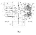
Fig. 1 is an illustration for showing the outline configuration of a wheeloil supply device 100 disposed in a wheel driving mechanism for driving awheel 101. -
Fig. 2 is an enlarged illustration of the region B of theoil supply device 100 inFig. 1 . - Hereafter, embodiments of the present invention will be explained, referring to the drawings.
- Awheel driving mechanism (may be referred to as a "wheel driving device") for driving independently the respective of a plurality of rundles (may be referred to as "wheels") 101 disposed in a vehicle is shown in
Fig. 1 . In this wheel driving mechanism, thewheel 101 is driven using the driving force by an electric motor (may be referred to as an "in-wheel motor") 110 which is a driving source. Thismotor 110 corresponds to an "in-wheel motor" in the present invention. Thewheel 101 is constituted by a tire (not shown) and adisk wheel 102. Thedisk wheel 102 comprises a rim for holding the tire and a disk connected with ahub 140. Thehub 140 is rotated by a driving force of themotor 110 and, thereby, thewheel 101 is driven. In addition, inFig. 1 and other drawings, the arrow D1 points toward the outside of the vehicle, and the arrow D2 points toward the inside of the vehicle. - In the
motor housing 111 of themotor 110, constituents, such as thestator core 112 with a stator coil wound thereon, therotor 113 and thegear 114, are contained. Therotor 113 extends along its long axis, and thegear 114 is integrally disposed at oneend 113a of therotor 113. Moreover, a permanent magnet is attached to therotor 113. Therefore, a rotating magnetic field is formed by applying an alternative-current to the stator coil wound around thestator core 112, and therotor 113 drawn to this rotating magnetic field rotates integrally with thegear 114. Thereby, the driving force by themotor 110 is transmitted to the rotation shaft (driving shaft) 121 engaging with thegear 114, and thisrotation shaft 121 rotates around the wheel axis A. - Moreover, the planetary gear (epicyclic gear) 130 is interposed between the
rotation shaft 121 and thehub 140. More specifically, theplanetary gear 130 is interposed between a sun gear (not shown) disposed on therotation shaft 121 and a ring gear (not shown) disposed on theinner race 104 fixed to the body side fixing member (typically, a knuckle or a carrier) 103. Thisplanetary gear 130 is intermeshed with the both of the sun gear and the ring gear, and is connected with thehub 140. Theplanetary gear 130 is revolving around the sun gear when therotation shaft 121 is rotationally driven, and thereby serves as a reducer which slows down a rotation of therotation shaft 121 and transmits the same to thehub 140. Thereby, thehub 140 is rotationally driven and, further, a driving force is transmitted to the wheel 101 (a tire and a disk wheel 102) connected with thishub 140. Thehub 140 is rotatably supported by the hub bearing 142 configured in a circular shape. Thehub 140 and the hub bearing 142 here correspond to a "hub" and a "hub bearing" in the present invention, respectively. - The above-mentioned wheel driving mechanism comprises the
disk brake mechanism 190 which gives a braking force to thewheel 101. Thisdisk brake mechanism 190 is arranged lateral to the hub bearing 142 in the radial direction, and comprises thebrake disc rotor 191 and thebrake caliper 192. Thebrake disc rotor 191 is fixed to thehub 140 and constituted as a member which rotates integrally with thewheel 101. Thebrake caliper 192 serves a function in producing a frictional force used as a braking force for thewheel 101, by pressing a brake pad, which is a friction material, to thebrake disc rotor 191. Thisdisk brake mechanism 190 corresponds to the "braking mechanism" in the present invention. - Moreover, the above-mentioned wheel driving mechanism comprises the
oil supply device 100 which is one embodiment of the "wheel oil supply devices" according to the present invention. Thisoil supply device 100 is assigned to thewheel 101. That is, it can be said that thisoil supply device 100 is one constituent of the wheel driving mechanism for thewheel 101. Thisoil supply device 100 comprises theoil pump 120, theoil reservoir 150, theintake pathway 160, the firstoil supply pathway 170, the firstoil discharge pathway 171, the secondoil supply pathway 180 and the secondoil discharge pathway 183. Theoil pump 120 is built in therotation shaft 121, and is operated by the rotational driving force of thisrotation shaft 121. The oil reservoir (may be referred to as a "reservoir tank") 150 serves a function in storing oil as lubricant or coolant (may be referred to as a "lube"). In a state where theoil pump 120 is operating, the oil stored in theoil reservoir 150 is inhaled by theoil pump 120 through theintake pathway 160 and its pressure is raised, and then discharged. Thisoil reservoir 150 corresponds to the "oil reservoir" in the present invention. - The oil discharged from the
oil pump 120 is supplied to the predetermined oil supply destinations of wheel driving mechanism through the respective of the firstoil supply pathway 170 and the secondoil supply pathway 180. Thereby, at the oil supply destinations, at least one of a lubrication function and a cooling function of oil is achieved. Thereafter, as for the firstoil supply pathway 170, the oil is discharged through the firstoil discharge pathway 171 to theoil reservoir 150 and thereby a circulation pathway of oil is established between the oil supply destination and theoil reservoir 150. Similarly, as for the secondoil supply pathway 180, the oil is discharged through the secondoil discharge pathway 183 to theoil reservoir 150 and thereby a circulation pathway of oil is established between the oil supply destination and theoil reservoir 150. - The first
oil supply pathway 170 is a route for connecting theoil pump 120 to the space in themotor housing 111 of theelectromotor 110, and the oil discharged from theoil pump 120 is supplied to oil supply destinations, such as a stator coil of themotor 110 and the reducer, through this firstoil supply pathway 170. In this case, theoil pump 120 and the firstoil supply pathway 170 constitute the mechanism ("first oil supply mechanism" in the present invention) for supplying oil to themotor 110. On the other hand, the secondoil supply pathway 180 is a route which connects theoil pump 120 and the hub bearing 142, and the oil discharged from theoil pump 120 is supplied to the hub bearing 142 through this secondoil supply pathway 180. In this case, theoil pump 120 and the secondoil supply pathway 180 constitute the mechanism ("second oil supply mechanism" in the present invention) for supplying oil to thehub bearing 142. Especially, the secondoil supply pathway 180 is constituted by theoil flow passages - The
oil flow passage 181 is a flow passage which extends in the direction of the wheel axis (extending direction of the wheel axis A) in the central part of thewheel 101 and through which oil is distributed from the inside of the wheel to the outside of the wheel. Thisoil flow passage 181 is formed so as to extend in the wheel axis direction within therotation shaft 121. That is, theoil flow passage 181 is constituted by therotation shaft 121. Theoil flow passage 182 is a flow passage for connecting theoil flow passage 181 and the region of thehub bearing 142. Thisoil flow passage 182 is formed within thehub 140. That is, theoil flow passage 182 is constituted by thehub 140. - Hereinafter, a concrete configuration of the above-mentioned
hub bearing 142 and its periphery will be explained, referring toFig. 2 . - As shown in
Fig. 2 , the hub bearing 142 comprises theinner race 104 which is a stator-side member, theouter race 141 which is a rotor-side member rotated integrally with thehub 140 in contrast to theinner race 104, and thebearing ball 143 held between theinner race 104 and theouter race 141. In this case, the compartmental region 144 (region inside the hub bearing 142) especially comparted by theouter periphery 105a of thecylindrical part 105 opposing in the radial direction and theinner periphery 141 a of the cylindricalouter race 141 becomes a rolling-motion region in which thebearing ball 143 rolls. This hub bearing 142 supports theouter race 141 in a rotatable way around theinner race 104. - In this hub bearing 142, the
oil seal 145 and thedust seal 146 both in a circular shape are attached to theouter race 141. - The
oil seal 145 is interposed between thehub bearing 142 and the region of the exterior of the hub bearing 142 (region 148 outside of the hub bearing), and its outer periphery is fixed to theouter race 141, and its inner periphery is equipped with the seal lip (oil lip) 145a. Thisseal lip 145a slidingly contacts theouter periphery 105a of thepart 105 opposing in the radial direction of theinner race 104. Therefore, when theouter race 141 rotates on the vehicle axis A around theinner race 104, theouter periphery 105a of thepart 105 opposing in the radial direction becomes a sliding surface which slidingly contacts theoil seal lip 145a of theoil seal 145, and a substantial oil seal function (function to seal the oil supplied to the hub bearing 142 through the second oil supply pathway 180) is attained on this sliding surface. Thisoil seal 145 corresponds to the "oil seal" in the present invention. - The
dust seal 146 is interposed between thehub bearing 142 and theregion 148 outside of the hub bearing, and its edge on the outer side of the vehicle is fixed to theouter race 141, and its edge on the inner side of the vehicle is equipped with the seal lip (dust lip) 146a. This seal lip 146a slidingly contacts the opposite surface 106a of thepart 106 opposing in the axial direction of theinner race 104. Therefore, when theouter race 141 rotates on the axle shaft A around theinner race 104, the opposite surface 106a of thepart 106 opposing in the axial direction becomes a sliding surface which slidingly contacts the seal lip 146a of thedust seal 146, and a substantial dust seal function (function to seal the dust which flows into the hub bearing 142) is attained in the sliding surface. Thisdust seal 146 corresponds to the "dust seal" in the present invention. Moreover, thisdust seal 146 comparts thespace 147 which is a part of theregion 148 outside of the hub bearing, along with theoil seal 145 and theinner race 104. - By the way, an external factor (typically, factors, such as a pump effect produced by the
hub 140 revolving at high speed and a pressure difference due to a temperature difference between thehub bearing 142 and theregion 148 outside of the hub bearing) over the hub bearing 142 can affect an oil leakage from thehub bearing 142. That is, there is a limit on completely sealing the oil supplied to the hub bearing 142 with the above-mentionedoil seal 145. Moreover, in thewheel 101 which is configured to be driven with driving force of themotor 110, in order to secure an installation space for a driving force transmission mechanism, such as a reducer interposed between themotor 110 and thehub 140, the diameter of the hub bearing 142 in a circular shape becomes larger compared with that in a configuration where themotor 110 is not mounted. In this case, if theouter race 141 rotates at a circumferential speed relatively high to theinner race 104, an air current from the hub bearing 142 toward theregion 148 outside of the hub bearing, which is a region other than thespace 147, via thespace 147 becomes more likely to be formed, due to a negative pressure (pressure difference between thehub bearing 142 and thespace 147 or theregion 148 outside of the hub bearing) generated according to a fluid suction action by theseal lip 145a when theseal lip 145a of theoil seal 145 slides on slidingsurface 105a of thepart 105 opposing in the radial direction of theinner race 104. As a result, due to the pressure difference generated between thehub bearing 142 and theregion 148 outside of the hub bearing across theseal lip 145a of theoil seal 145, an oil leakage from the hub bearing 142 becomes more likely to occur. Especially, when the oil which has leaked from the hub bearing 142 to theregion 148 outside of the hub bearing flows into the brake components such as thedisk brake mechanism 190, it is concerned that the braking force of thewheel 101 may decrease. - Then, in this embodiment, the communicating
pathway 149 constituted by thepassage hole 103a formed within the bodyside fixing member 103 and thepassage 104a formed within theinner race 104 is formed. One end of this communicatingpathway 149 communicates with thespace 147 and the other end thereof communicates with the secondoil discharge pathway 183. Therefore, thespace 147 and the communicatingpathway 149 serves as an oil guiding pathway which guides the oil which leaked from the hub bearing 142 to theregion 148 outside of the hub bearing through theoil seal 145 to a predetermined discharge region (in this embodiment, the oil reservoir 150). In this case, theoil reservoir 150 which is a discharge region is disposed in the region except thedisk brake mechanism 190 among the regions in the vehicle or wheel driving mechanism. Here, thespace 147 and the communicatingpathway 149 correspond to the "space" and "communicating pathway" in the present invention, respectively. Moreover, the secondoil discharge pathway 183, in addition to thespace 147 and the communicatingpathway 149, constitute the "oil guiding pathway" in the present invention. - Thereby, when the oil supplied to the hub bearing 142 leaks thereafter from between the sliding
surface 105a of thepart 105 opposing in the radial direction of theinner race 104 and theseal lip 145a of theoil seal 145, this oil flows into the communicatingpathway 149 via thespace 147. As a result, the oil which flew through the communicatingpathway 149 is discharged to theoil reservoir 150 through the secondoil discharge pathway 183, and the circulation pathway of oil is established between thehub bearing 142 and theoil reservoir 150. Thereby, the oil which leaked from the hub bearing 142 can be reasonably recycled without a loss. Moreover, according to this conformation, since no measure such as addition of another component for preventing the oil leakage from the hub bearing 142 to theregion 148 outside a hub bearing is needed, as compared with such measure, the cost reduction effect of a product can be acquired while simplifying its configuration. - Moreover, since the
space 147 communicates with the 2ndoil discharge pathway 183 through the communicatingpathway 149, the pressure difference generated between thehub bearing 142 and theregion 148 outside of the hub bearing across theseal lip 145a of theoil seal 145 due to a negative pressure resulting from a fluid suction action by the seal lip145a can be prevented from generating. As a result, the oil which leaked from the hub bearing 142 to thespace 147 comes to preferentially flow into the communicatingpathway 149, the oil can be prevented from flowing into the brake components, such as thedisk brake mechanism 190, and an unexpected region where the oil has a bad influence within theregion 148 outside of the hub bearing. Especially, by preventing the oil which leaked from the hub bearing 142 from flowing into thedisk brake mechanism 190, the braking force of thewheel 101 can be prevented from declining. In this way, anoil supply device 100 suitable for the wheel driving device which drives thewheel 101 with the driving force of themotor 110 can be achieved. - The present invention is not limited only to the above-mentioned typical embodiments, and various applications and modifications can be supposed. For example, the following embodiments which are applications of the above-mentioned embodiments can be also implemented.
- Although the
oil reservoir 150 was disposed as a discharge region to which the oil which leaked from the hub bearing 142 to thespace 147 is discharged in the above-mentioned embodiment, in accordance with the present invention, various regions other than theoil reservoir 150, especially the region excluding the braking mechanism, can be preferably chosen as this discharge region. - Although the route constituted by a combination of the
space 147 and the communicatingpathway 149 was used as an oil guiding pathway which guides the oil which leaked from the hub bearing 142 to theregion 148 outside of the hub bearing to theoil reservoir 150 in the above-mentioned embodiment, in accordance with the present invention, the configuration of an oil guiding pathway is not limited to this, and an oil guiding pathway can be constituted using at least one of a space and a communicating pathway in a shape of groove or hole, for example. - Although the
space 147 was comparted using theoil seal 145 and thedust seal 146 in the above-mentioned embodiment, in accordance with the present invention, a region which corresponds to thespace 147 can be comparted and formed using at least a member which corresponds to theoil seal 145. In this case, thedust seal 146 can be omitted, if necessary. - Although the
oil supply device 100 which was assigned to the wheel driving mechanism in which themotor 110 was the driving source of thewheel 101 was described in the above-mentioned embodiment, the present invention can be applied to an oil supply device which is assigned to a wheel driving mechanism in which all or a portion of the driving source of the wheel is a driving source other than the motor 110 (typically, an internal-combustion engine).
Claims (5)
- Awheel oil supply device, which is assigned to a wheel of a vehicle, comprising:an oil supply pathway for supplying oil to a hub bearing, which rotatably supports a hub connected to a disk wheel of said wheel,an oil seal which is interposed between said hub bearing and a region outside of the hub bearing to seal the oil supplied to said hub bearing through said oil supply pathway, andan oil guiding pathway for guiding the oil which has leaked from said hub bearing to said region outside of the hub bearing through said oil seal, to a predetermined discharge region.
- The wheel oil supply device according to Claim 1, further comprising:a dust seal which is interposed between said hub bearing and said region outside of the hub bearing to seal a dust which flows from said region outside of the hub bearing to said hub bearing, andwherein:said oil guiding pathway comprises a space which is comparted within said region outside of the hub bearing by said oil seal and said dust seal and a communicating pathway which makes said space communicate with said discharge region.
- The wheel oil supply device according to Claim 1 or 2, wherein:said discharge region is disposed in a region other than a braking mechanism which gives a braking force to said wheel.
- The wheel oil supply device according to any one of Claims 1 to 3, wherein:said discharge region is an oil reservoir which stores oil to be supplied to said hub bearing.
- Awheel driving device which drives a wheel of a vehicle, comprising:an electric in-wheel motor which is disposed as a driving source of said wheel,a hub which is connected with a disk wheel of said wheel and rotated by the driving force of said in-wheel motor,a hub bearing which rotatably supports said hub,a first oil supply mechanism for supplying oil to said in-wheel motor, anda second oil supply mechanism for supplying oil to said hub bearing, andwherein:said second oil supply mechanism is constituted by the wheel oil supply device according to any one of Claims 1 to 4.
Applications Claiming Priority (1)
| Application Number | Priority Date | Filing Date | Title |
|---|---|---|---|
| PCT/JP2012/083801 WO2014102949A1 (en) | 2012-12-27 | 2012-12-27 | Wheel oil supply device and wheel driving device |
Publications (2)
| Publication Number | Publication Date |
|---|---|
| EP2940328A1 true EP2940328A1 (en) | 2015-11-04 |
| EP2940328A4 EP2940328A4 (en) | 2016-11-23 |
Family
ID=51020105
Family Applications (1)
| Application Number | Title | Priority Date | Filing Date |
|---|---|---|---|
| EP12891320.9A Withdrawn EP2940328A4 (en) | 2012-12-27 | 2012-12-27 | OIL SUPPLY DEVICE FOR WHEEL, AND WHEEL DRIVE DEVICE |
Country Status (5)
| Country | Link |
|---|---|
| US (1) | US9387722B2 (en) |
| EP (1) | EP2940328A4 (en) |
| JP (1) | JPWO2014102949A1 (en) |
| CN (1) | CN104884829A (en) |
| WO (1) | WO2014102949A1 (en) |
Families Citing this family (8)
| Publication number | Priority date | Publication date | Assignee | Title |
|---|---|---|---|---|
| US9853523B2 (en) | 2015-08-29 | 2017-12-26 | Fairfield Manufacturing Company, Inc. | Wheel motor cooling system with equally divided flow |
| US9505299B1 (en) * | 2015-10-07 | 2016-11-29 | Deere & Company | Fluid evacuation system for drive chamber |
| JP6794768B2 (en) * | 2016-10-19 | 2020-12-02 | トヨタ自動車株式会社 | In-wheel motor oil leak monitoring structure |
| DE102017208742A1 (en) * | 2017-05-23 | 2018-11-29 | Zf Friedrichshafen Ag | Radkopfanordnung |
| CN108870055A (en) * | 2018-08-07 | 2018-11-23 | 湖北火鑫消防车辆装备有限公司 | A kind of circulating cooling system of vehicle drive wheels axle oil |
| CN108953972A (en) * | 2018-08-07 | 2018-12-07 | 湖北火鑫消防车辆装备有限公司 | A kind of circulating cooling system of vehicle follower shaft bearing lubrication oil |
| CN113954577B (en) * | 2021-11-17 | 2024-03-12 | 浙江四和机械有限公司 | Light-weight energy-saving hub unit with ABS sensor |
| CN118665151A (en) * | 2023-03-14 | 2024-09-20 | 舍弗勒技术股份两合公司 | Wheel hub drive system |
Family Cites Families (22)
| Publication number | Priority date | Publication date | Assignee | Title |
|---|---|---|---|---|
| US3770074A (en) * | 1972-04-24 | 1973-11-06 | Gen Motors Corp | Reduction drive for electric axle |
| JPS58105805A (en) | 1981-12-18 | 1983-06-23 | Nissan Motor Co Ltd | Structure of axle for automobile |
| JPS6122927U (en) | 1984-07-13 | 1986-02-10 | ダイハツ工業株式会社 | Dust-proof structure of oil seal on drive axle |
| JPH0527432U (en) | 1991-09-24 | 1993-04-09 | 日産デイーゼル工業株式会社 | Dustproof structure of oil seal part in vehicle drive system |
| JP3211315B2 (en) | 1991-12-25 | 2001-09-25 | アイシン・エィ・ダブリュ株式会社 | Cooling control device for motor for vehicle |
| JP3171009B2 (en) * | 1994-06-20 | 2001-05-28 | トヨタ自動車株式会社 | Variable valve timing device for internal combustion engine |
| JP3287226B2 (en) | 1996-07-02 | 2002-06-04 | 三菱自動車工業株式会社 | Wheel drive with hub reducer |
| JP4383802B2 (en) * | 2003-08-25 | 2009-12-16 | トヨタ自動車株式会社 | In-wheel motor |
| CN2713212Y (en) * | 2004-05-18 | 2005-07-27 | 郑小平 | Self-circulation lubricating device for bearing |
| CN2713229Y (en) * | 2004-05-18 | 2005-07-27 | 郑小平 | Mechanical sealing device |
| JP4550631B2 (en) * | 2005-03-11 | 2010-09-22 | 本田技研工業株式会社 | Wheel drive device for vehicle |
| JP4508027B2 (en) * | 2005-07-29 | 2010-07-21 | トヨタ自動車株式会社 | Internal combustion engine starting torque transmission mechanism |
| JP2007237834A (en) | 2006-03-07 | 2007-09-20 | Nissan Motor Co Ltd | Wheel-in motor mounting structure |
| JP2009012523A (en) * | 2007-07-02 | 2009-01-22 | Toyota Motor Corp | Wheel drive device |
| JP5266883B2 (en) * | 2008-05-29 | 2013-08-21 | トヨタ自動車株式会社 | In-wheel motor cooling device |
| JP5157650B2 (en) * | 2008-06-02 | 2013-03-06 | トヨタ自動車株式会社 | In-wheel motor cooling structure |
| JP5009943B2 (en) * | 2009-01-28 | 2012-08-29 | 日立建機株式会社 | Travel drive device for work vehicle |
| US8545106B2 (en) * | 2009-07-08 | 2013-10-01 | Williams International Co., L.L.C. | System and method for isolating a rolling-element bearing |
| JP5565388B2 (en) * | 2011-03-28 | 2014-08-06 | アイシン・エィ・ダブリュ株式会社 | In-wheel motor drive device |
| JP6041861B2 (en) * | 2011-04-05 | 2016-12-14 | テュッセンクルップ ローテ エルデ ゲーエムベーハー | Oil lubricated anti-friction bearing |
| JP5496973B2 (en) * | 2011-09-06 | 2014-05-21 | 日立建機株式会社 | Dump truck travel drive device |
| US8662277B2 (en) * | 2011-12-22 | 2014-03-04 | Fairfield Manufacturing Company, Inc. | Planetary gearbox with integral service brake |
-
2012
- 2012-12-27 EP EP12891320.9A patent/EP2940328A4/en not_active Withdrawn
- 2012-12-27 CN CN201280078037.5A patent/CN104884829A/en active Pending
- 2012-12-27 WO PCT/JP2012/083801 patent/WO2014102949A1/en not_active Ceased
- 2012-12-27 JP JP2014553953A patent/JPWO2014102949A1/en active Pending
- 2012-12-27 US US14/655,511 patent/US9387722B2/en not_active Expired - Fee Related
Also Published As
| Publication number | Publication date |
|---|---|
| JPWO2014102949A1 (en) | 2017-01-12 |
| US9387722B2 (en) | 2016-07-12 |
| US20150328925A1 (en) | 2015-11-19 |
| CN104884829A (en) | 2015-09-02 |
| WO2014102949A1 (en) | 2014-07-03 |
| EP2940328A4 (en) | 2016-11-23 |
Similar Documents
| Publication | Publication Date | Title |
|---|---|---|
| US9387722B2 (en) | Wheel oil supply device and wheel driving device | |
| US7350605B2 (en) | In-wheel motor capable of efficiently cooling electric motor and reduction gear | |
| CN101121394B (en) | In-wheel motor and wheel assembly having the same | |
| EP2282394A1 (en) | Drive device for vehicle | |
| JP5066925B2 (en) | Wheel drive device | |
| US8678115B2 (en) | Vehicle drive device | |
| US20230261539A1 (en) | In-wheel motor for electric vehicle and sealing apparatus for protecting in-wheel motor | |
| JP5297758B2 (en) | In-wheel motor drive device | |
| CN102826003B (en) | Wheel inner driving device | |
| JP6065805B2 (en) | Electric motor | |
| JP2008178225A (en) | Rotating electric machine | |
| CN105705451B (en) | elevator traction machine | |
| WO2012140963A1 (en) | Lubrication control device for in-wheel motor unit for vehicle | |
| JP7494763B2 (en) | Fluid Machinery | |
| JP2009201217A (en) | Lubrication/cooling structure of electric motor | |
| WO2012120651A1 (en) | Drive device for electric vehicle | |
| CN114600343A (en) | Lubricant-supported rotor structure | |
| JP2015116900A (en) | Wheel drive device | |
| WO2023113034A1 (en) | In-wheel motor | |
| JP2016101879A (en) | Drive device for vehicle and assembly method of the same | |
| US11519490B2 (en) | Oil supply unit | |
| US20250055348A1 (en) | In-wheel motor | |
| JP2009201216A (en) | Cooling structure for electric motor | |
| US20250055344A1 (en) | In-wheel motor | |
| JP2010180730A (en) | Electric pump unit |
Legal Events
| Date | Code | Title | Description |
|---|---|---|---|
| PUAI | Public reference made under article 153(3) epc to a published international application that has entered the european phase |
Free format text: ORIGINAL CODE: 0009012 |
|
| 17P | Request for examination filed |
Effective date: 20150625 |
|
| AK | Designated contracting states |
Kind code of ref document: A1 Designated state(s): AL AT BE BG CH CY CZ DE DK EE ES FI FR GB GR HR HU IE IS IT LI LT LU LV MC MK MT NL NO PL PT RO RS SE SI SK SM TR |
|
| AX | Request for extension of the european patent |
Extension state: BA ME |
|
| DAX | Request for extension of the european patent (deleted) | ||
| STAA | Information on the status of an ep patent application or granted ep patent |
Free format text: STATUS: THE APPLICATION HAS BEEN WITHDRAWN |
|
| A4 | Supplementary search report drawn up and despatched |
Effective date: 20161025 |
|
| RIC1 | Information provided on ipc code assigned before grant |
Ipc: F16C 33/66 20060101AFI20161019BHEP Ipc: F16C 19/18 20060101ALI20161019BHEP Ipc: B60K 7/00 20060101ALI20161019BHEP Ipc: B60B 27/00 20060101ALI20161019BHEP |
|
| 18W | Application withdrawn |
Effective date: 20161110 |