EP2940182B1 - Roll - Google Patents
Roll Download PDFInfo
- Publication number
- EP2940182B1 EP2940182B1 EP13857783.8A EP13857783A EP2940182B1 EP 2940182 B1 EP2940182 B1 EP 2940182B1 EP 13857783 A EP13857783 A EP 13857783A EP 2940182 B1 EP2940182 B1 EP 2940182B1
- Authority
- EP
- European Patent Office
- Prior art keywords
- substrate
- region
- roll
- precursor
- transferring
- Prior art date
- Legal status (The legal status is an assumption and is not a legal conclusion. Google has not performed a legal analysis and makes no representation as to the accuracy of the status listed.)
- Active
Links
- 239000000758 substrate Substances 0.000 claims description 157
- 239000002243 precursor Substances 0.000 claims description 68
- 238000000034 method Methods 0.000 claims description 42
- 230000008569 process Effects 0.000 claims description 25
- 238000012546 transfer Methods 0.000 claims description 14
- 238000005507 spraying Methods 0.000 claims description 11
- 239000011261 inert gas Substances 0.000 claims description 9
- 230000008859 change Effects 0.000 claims description 4
- 239000002985 plastic film Substances 0.000 claims description 4
- 229920006255 plastic film Polymers 0.000 claims description 4
- 239000010408 film Substances 0.000 description 61
- 238000000231 atomic layer deposition Methods 0.000 description 15
- 239000010410 layer Substances 0.000 description 15
- 239000007789 gas Substances 0.000 description 9
- 239000002356 single layer Substances 0.000 description 8
- 238000010926 purge Methods 0.000 description 4
- 238000000576 coating method Methods 0.000 description 3
- 230000001276 controlling effect Effects 0.000 description 3
- 238000002347 injection Methods 0.000 description 3
- 239000007924 injection Substances 0.000 description 3
- 239000000463 material Substances 0.000 description 3
- 230000007246 mechanism Effects 0.000 description 3
- 230000004888 barrier function Effects 0.000 description 2
- 239000011248 coating agent Substances 0.000 description 2
- 230000000694 effects Effects 0.000 description 2
- 239000007788 liquid Substances 0.000 description 2
- 238000005086 pumping Methods 0.000 description 2
- 230000001419 dependent effect Effects 0.000 description 1
- 230000000994 depressogenic effect Effects 0.000 description 1
- 238000010586 diagram Methods 0.000 description 1
- 238000001962 electrophoresis Methods 0.000 description 1
- 238000005516 engineering process Methods 0.000 description 1
- 239000011521 glass Substances 0.000 description 1
- 230000005525 hole transport Effects 0.000 description 1
- 238000009434 installation Methods 0.000 description 1
- 239000004973 liquid crystal related substance Substances 0.000 description 1
- 238000012423 maintenance Methods 0.000 description 1
- 238000012986 modification Methods 0.000 description 1
- 230000004048 modification Effects 0.000 description 1
- 230000003287 optical effect Effects 0.000 description 1
- 239000000843 powder Substances 0.000 description 1
- 230000002265 prevention Effects 0.000 description 1
- 238000012545 processing Methods 0.000 description 1
- 230000001105 regulatory effect Effects 0.000 description 1
- 239000007787 solid Substances 0.000 description 1
- 239000007921 spray Substances 0.000 description 1
- 238000004544 sputter deposition Methods 0.000 description 1
- 239000010409 thin film Substances 0.000 description 1
Images


Classifications
-
- C—CHEMISTRY; METALLURGY
- C23—COATING METALLIC MATERIAL; COATING MATERIAL WITH METALLIC MATERIAL; CHEMICAL SURFACE TREATMENT; DIFFUSION TREATMENT OF METALLIC MATERIAL; COATING BY VACUUM EVAPORATION, BY SPUTTERING, BY ION IMPLANTATION OR BY CHEMICAL VAPOUR DEPOSITION, IN GENERAL; INHIBITING CORROSION OF METALLIC MATERIAL OR INCRUSTATION IN GENERAL
- C23C—COATING METALLIC MATERIAL; COATING MATERIAL WITH METALLIC MATERIAL; SURFACE TREATMENT OF METALLIC MATERIAL BY DIFFUSION INTO THE SURFACE, BY CHEMICAL CONVERSION OR SUBSTITUTION; COATING BY VACUUM EVAPORATION, BY SPUTTERING, BY ION IMPLANTATION OR BY CHEMICAL VAPOUR DEPOSITION, IN GENERAL
- C23C16/00—Chemical coating by decomposition of gaseous compounds, without leaving reaction products of surface material in the coating, i.e. chemical vapour deposition [CVD] processes
- C23C16/44—Chemical coating by decomposition of gaseous compounds, without leaving reaction products of surface material in the coating, i.e. chemical vapour deposition [CVD] processes characterised by the method of coating
- C23C16/458—Chemical coating by decomposition of gaseous compounds, without leaving reaction products of surface material in the coating, i.e. chemical vapour deposition [CVD] processes characterised by the method of coating characterised by the method used for supporting substrates in the reaction chamber
-
- B—PERFORMING OPERATIONS; TRANSPORTING
- B65—CONVEYING; PACKING; STORING; HANDLING THIN OR FILAMENTARY MATERIAL
- B65H—HANDLING THIN OR FILAMENTARY MATERIAL, e.g. SHEETS, WEBS, CABLES
- B65H23/00—Registering, tensioning, smoothing or guiding webs
- B65H23/02—Registering, tensioning, smoothing or guiding webs transversely
- B65H23/022—Registering, tensioning, smoothing or guiding webs transversely by tentering devices
- B65H23/025—Registering, tensioning, smoothing or guiding webs transversely by tentering devices by rollers
- B65H23/0251—Registering, tensioning, smoothing or guiding webs transversely by tentering devices by rollers with a straight axis
-
- B—PERFORMING OPERATIONS; TRANSPORTING
- B65—CONVEYING; PACKING; STORING; HANDLING THIN OR FILAMENTARY MATERIAL
- B65H—HANDLING THIN OR FILAMENTARY MATERIAL, e.g. SHEETS, WEBS, CABLES
- B65H27/00—Special constructions, e.g. surface features, of feed or guide rollers for webs
-
- C—CHEMISTRY; METALLURGY
- C23—COATING METALLIC MATERIAL; COATING MATERIAL WITH METALLIC MATERIAL; CHEMICAL SURFACE TREATMENT; DIFFUSION TREATMENT OF METALLIC MATERIAL; COATING BY VACUUM EVAPORATION, BY SPUTTERING, BY ION IMPLANTATION OR BY CHEMICAL VAPOUR DEPOSITION, IN GENERAL; INHIBITING CORROSION OF METALLIC MATERIAL OR INCRUSTATION IN GENERAL
- C23C—COATING METALLIC MATERIAL; COATING MATERIAL WITH METALLIC MATERIAL; SURFACE TREATMENT OF METALLIC MATERIAL BY DIFFUSION INTO THE SURFACE, BY CHEMICAL CONVERSION OR SUBSTITUTION; COATING BY VACUUM EVAPORATION, BY SPUTTERING, BY ION IMPLANTATION OR BY CHEMICAL VAPOUR DEPOSITION, IN GENERAL
- C23C16/00—Chemical coating by decomposition of gaseous compounds, without leaving reaction products of surface material in the coating, i.e. chemical vapour deposition [CVD] processes
- C23C16/44—Chemical coating by decomposition of gaseous compounds, without leaving reaction products of surface material in the coating, i.e. chemical vapour deposition [CVD] processes characterised by the method of coating
- C23C16/455—Chemical coating by decomposition of gaseous compounds, without leaving reaction products of surface material in the coating, i.e. chemical vapour deposition [CVD] processes characterised by the method of coating characterised by the method used for introducing gases into reaction chamber or for modifying gas flows in reaction chamber
- C23C16/45523—Pulsed gas flow or change of composition over time
- C23C16/45525—Atomic layer deposition [ALD]
- C23C16/45544—Atomic layer deposition [ALD] characterized by the apparatus
-
- C—CHEMISTRY; METALLURGY
- C23—COATING METALLIC MATERIAL; COATING MATERIAL WITH METALLIC MATERIAL; CHEMICAL SURFACE TREATMENT; DIFFUSION TREATMENT OF METALLIC MATERIAL; COATING BY VACUUM EVAPORATION, BY SPUTTERING, BY ION IMPLANTATION OR BY CHEMICAL VAPOUR DEPOSITION, IN GENERAL; INHIBITING CORROSION OF METALLIC MATERIAL OR INCRUSTATION IN GENERAL
- C23C—COATING METALLIC MATERIAL; COATING MATERIAL WITH METALLIC MATERIAL; SURFACE TREATMENT OF METALLIC MATERIAL BY DIFFUSION INTO THE SURFACE, BY CHEMICAL CONVERSION OR SUBSTITUTION; COATING BY VACUUM EVAPORATION, BY SPUTTERING, BY ION IMPLANTATION OR BY CHEMICAL VAPOUR DEPOSITION, IN GENERAL
- C23C16/00—Chemical coating by decomposition of gaseous compounds, without leaving reaction products of surface material in the coating, i.e. chemical vapour deposition [CVD] processes
- C23C16/44—Chemical coating by decomposition of gaseous compounds, without leaving reaction products of surface material in the coating, i.e. chemical vapour deposition [CVD] processes characterised by the method of coating
- C23C16/54—Apparatus specially adapted for continuous coating
- C23C16/545—Apparatus specially adapted for continuous coating for coating elongated substrates
-
- H—ELECTRICITY
- H01—ELECTRIC ELEMENTS
- H01L—SEMICONDUCTOR DEVICES NOT COVERED BY CLASS H10
- H01L21/00—Processes or apparatus adapted for the manufacture or treatment of semiconductor or solid state devices or of parts thereof
- H01L21/02—Manufacture or treatment of semiconductor devices or of parts thereof
- H01L21/02104—Forming layers
- H01L21/02365—Forming inorganic semiconducting materials on a substrate
- H01L21/02612—Formation types
- H01L21/02617—Deposition types
- H01L21/0262—Reduction or decomposition of gaseous compounds, e.g. CVD
-
- H—ELECTRICITY
- H01—ELECTRIC ELEMENTS
- H01L—SEMICONDUCTOR DEVICES NOT COVERED BY CLASS H10
- H01L21/00—Processes or apparatus adapted for the manufacture or treatment of semiconductor or solid state devices or of parts thereof
- H01L21/67—Apparatus specially adapted for handling semiconductor or electric solid state devices during manufacture or treatment thereof; Apparatus specially adapted for handling wafers during manufacture or treatment of semiconductor or electric solid state devices or components ; Apparatus not specifically provided for elsewhere
- H01L21/67005—Apparatus not specifically provided for elsewhere
- H01L21/67011—Apparatus for manufacture or treatment
- H01L21/67132—Apparatus for placing on an insulating substrate, e.g. tape
-
- H—ELECTRICITY
- H01—ELECTRIC ELEMENTS
- H01L—SEMICONDUCTOR DEVICES NOT COVERED BY CLASS H10
- H01L21/00—Processes or apparatus adapted for the manufacture or treatment of semiconductor or solid state devices or of parts thereof
- H01L21/67—Apparatus specially adapted for handling semiconductor or electric solid state devices during manufacture or treatment thereof; Apparatus specially adapted for handling wafers during manufacture or treatment of semiconductor or electric solid state devices or components ; Apparatus not specifically provided for elsewhere
- H01L21/677—Apparatus specially adapted for handling semiconductor or electric solid state devices during manufacture or treatment thereof; Apparatus specially adapted for handling wafers during manufacture or treatment of semiconductor or electric solid state devices or components ; Apparatus not specifically provided for elsewhere for conveying, e.g. between different workstations
- H01L21/67703—Apparatus specially adapted for handling semiconductor or electric solid state devices during manufacture or treatment thereof; Apparatus specially adapted for handling wafers during manufacture or treatment of semiconductor or electric solid state devices or components ; Apparatus not specifically provided for elsewhere for conveying, e.g. between different workstations between different workstations
- H01L21/67706—Mechanical details, e.g. roller, belt
-
- B—PERFORMING OPERATIONS; TRANSPORTING
- B65—CONVEYING; PACKING; STORING; HANDLING THIN OR FILAMENTARY MATERIAL
- B65H—HANDLING THIN OR FILAMENTARY MATERIAL, e.g. SHEETS, WEBS, CABLES
- B65H2404/00—Parts for transporting or guiding the handled material
- B65H2404/10—Rollers
- B65H2404/13—Details of longitudinal profile
- B65H2404/131—Details of longitudinal profile shape
- B65H2404/1317—End profile
-
- B—PERFORMING OPERATIONS; TRANSPORTING
- B65—CONVEYING; PACKING; STORING; HANDLING THIN OR FILAMENTARY MATERIAL
- B65H—HANDLING THIN OR FILAMENTARY MATERIAL, e.g. SHEETS, WEBS, CABLES
- B65H2404/00—Parts for transporting or guiding the handled material
- B65H2404/10—Rollers
- B65H2404/13—Details of longitudinal profile
- B65H2404/132—Details of longitudinal profile arrangement of segments along axis
-
- B—PERFORMING OPERATIONS; TRANSPORTING
- B65—CONVEYING; PACKING; STORING; HANDLING THIN OR FILAMENTARY MATERIAL
- B65H—HANDLING THIN OR FILAMENTARY MATERIAL, e.g. SHEETS, WEBS, CABLES
- B65H2404/00—Parts for transporting or guiding the handled material
- B65H2404/50—Surface of the elements in contact with the forwarded or guided material
- B65H2404/52—Surface of the elements in contact with the forwarded or guided material other geometrical properties
- B65H2404/521—Reliefs
- B65H2404/5211—Reliefs only a part of the element in contact with the forwarded or guided material
-
- B—PERFORMING OPERATIONS; TRANSPORTING
- B65—CONVEYING; PACKING; STORING; HANDLING THIN OR FILAMENTARY MATERIAL
- B65H—HANDLING THIN OR FILAMENTARY MATERIAL, e.g. SHEETS, WEBS, CABLES
- B65H2701/00—Handled material; Storage means
- B65H2701/10—Handled articles or webs
- B65H2701/13—Parts concerned of the handled material
- B65H2701/132—Side portions
-
- B—PERFORMING OPERATIONS; TRANSPORTING
- B65—CONVEYING; PACKING; STORING; HANDLING THIN OR FILAMENTARY MATERIAL
- B65H—HANDLING THIN OR FILAMENTARY MATERIAL, e.g. SHEETS, WEBS, CABLES
- B65H2801/00—Application field
- B65H2801/61—Display device manufacture, e.g. liquid crystal displays
Definitions
- the present invention relates to a roll, a film forming apparatus, and a film forming method.
- a technology for forming various kinds of films may be required in various fields, for example, forming of a conformal coating such as a barrier layer, a flexible display coating required in an electroluminescent display, a liquid crystal display (LCD), electrophoresis, or the like, radio frequency identification (RFID), microelectromechanical systems (MEMS), optical coatings, electronic components on a flexible substrate, thin films on the flexible substrate, electrochromics, photoelectromotive force, and the like.
- a conformal coating such as a barrier layer, a flexible display coating required in an electroluminescent display, a liquid crystal display (LCD), electrophoresis, or the like, radio frequency identification (RFID), microelectromechanical systems (MEMS), optical coatings, electronic components on a flexible substrate, thin films on the flexible substrate, electrochromics, photoelectromotive force, and the like.
- RFID radio frequency identification
- MEMS microelectromechanical systems
- JP 2012201899 A discloses a guide roll for film forming apparatuses and methods, with the ends of a larger diameter and configured to supply a precursor to the substrate at a central portion of the roll, while the precursor is injected through a side surface.
- This prior art document also discloses an atomic layer deposition film forming apparatus with a transfer region and a treating region, and the roll is installed and guides and transfers the substrate.
- WO 2012/133541 A1 discloses a roll, an apparatus and an atomic layer deposition method. Precursor is supplied and exhausted in the treating regions, and the guide rolls form a path along which the substrate passes through the treating regions in turn.
- the substrate can be a plastic film, metallic web or fibrous film.
- the present invention is directed to a roll, a film forming apparatus, and a film forming method.
- a roll used as a guide roll of a film forming apparatus which comprises a transferring unit including one or more guide rolls installed to transfer a substrate; and a treating region installed to form a film on a surface of the substrate transferred by the transferring unit, wherein the roll comprises a supplying unit configured to supply a precursor to the substrate during a transferring process of the substrate, wherein the roll comprising the supplying unit is disposed in the treating region, wherein the roll has a structure in which a central portion does not exist so as to be in contact with both ends of the substrate in a direction perpendicular to the transferring direction of the substrate, but not in contact with other portions of the substrate, and the supplying unit is formed at an inner side surface of the end.
- a film forming apparatus comprising: a transferring unit including one or more guide rolls installed to transfer a substrate; and a treating region installed to form a film on a surface of the substrate transferred by the transferring unit, wherein at least one of the guide rolls is the roll of the present invention.
- the film forming apparatus may be, for example, an atomic layer deposition (ALD) apparatus which forms a film by an ALD.
- ALD atomic layer deposition
- a film forming method which forms a film on a substrate, for example, a flexible substrate such as a plastic film and a metallic or fibrous web or film.
- FIG. 7 are views illustrating the exemplary embodiments according to the invention defined in the appended claims.
- An exemplary roll may be a roll used for transferring a substrate.
- FIG. 1 illustrates an exemplary roll.
- the roll may include both ends 210 which are in contact with a substrate 101, and a central portion 220 which is not in contact with the substrate 101.
- a ratio Rc/Re of a diameter Rc of the central portion 220 to a diameter Re of each of the ends 210 is not particularly limited, but may be controlled to enable the substrate 101 to be properly transferred.
- the ratio Rc/Re may be 0.9 or less, or 0.5 to 0.9. In the structure in which the central portion does not exist, the ratio Rc/Re is 0.
- a distance Lc between the both ends 210, in a case that there is not the central portion 220, to a length L of the roll, which is measured in a direction perpendicular to a transferring direction of the substrate 101, is not particularly limited, either, as long as the ends 210 may be secured so as to properly fix the substrate during the transferring process.
- the ratio Lc/L may be 0.7 to 0.9.
- a protruding portion may be provided at each of the ends of the roll in order to fix the substrate during the transferring process. Since the substrate is fixed by the protruding portion during the transferring process, the substrate may be prevented from being separated or slid.
- the roll has only the both ends without the central portion.
- the both ends of the roll may be formed to fix the substrate, while applying a tensile force to the substrate in one direction within an angular range of 70° to 110° with respect to the transferring direction of the substrate, e.g., a vertical direction during the transferring process of the substrate.
- the ends may be formed to be movable while tensing the substrate in the one direction within the angular range of 70° to 110° with respect to the transferring direction of the substrate, e.g., the vertical direction.
- patterns of the ends or the protruding portions provided at the ends may be formed so as to transfer and tense the substrate at the same time.
- FIGS. 2 to 5 are views exemplarily illustrating the above mentioned structures.
- the roll may have the structure having only the both ends 210.
- the substrate 101 is fixed to protruding portions 310 of the both ends 210, and the both ends 210 are horizontally moved, and thus the substrate 101 may be transferred while being tensed.
- the structure in FIG. 2 may be applied to a roll having the central portion 220, as illustrated in FIG. 3 .
- FIG. 4 is a view illustrating another type which may transfer the substrate 101 while applying the tensile force to the substrate 101.
- the protruding portion 310 may be formed into a predetermined pattern.
- the pattern of the protruding portion 310 is not particularly limited.
- the protruding pattern may include a line shape which forms an angle larger than 0° and less than 90° with respect to a movement direction (the transferring direction) of the substrate.
- the line shape may be, for example, a comb shape, i.e., a shape illustrated in FIG. 4 .
- FIG. 5 is a view illustrating yet another type of the structure. As illustrated in FIG. 5 , even when each of the both ends 210 has a tapered shape, it is possible to embody the structure which may transfer the substrate 101 while applying the tensile force to the substrate 101. This structure may make an effect in which the both ends 210 pull the substrate 101 in both directions during the transferring process of the substrate 101.
- the exemplary roll may be a roll (hereinafter, called a precursor supplying roll, or a supplying roll) which is used for transferring the substrate, as described above, and installed to supply a precursor to substrate transferred.
- a precursor supplying roll or a supplying roll
- the precursor supplying roll has a precursor supplying unit for supplying the precursor.
- the precursor supplying roll may have a structure in having only the ends without the central portion. In these structures, a position of the precursor supplying unit is not particularly limited.
- the precursor supplying unit is provided at an inner side surface of each of the ends.
- the supplying roll may include the both ends, and the both ends may be installed to be in contact with and transfer the substrate, and the central portion does not exist so as not to be in contact with the substrate during a transferring process of the substrate.
- FIG. 6 illustrates an exemplary supplying roll.
- the supplying roll may include both ends 210 which are in contact with a substrate 101, and a central portion 220 which is not in contact with the substrate 101.
- a ratio Rc/Re of a diameter Rc of the central portion 220 to a diameter Re of each of the ends 210 is not particularly limited, but may be controlled to enable the substrate 101 to be properly transferred and also to secure a sufficient distance for efficiently forming a monolayer on the substrate 101 with the supplied precursor.
- the ratio Rc/Re may be 0.9 or less. In the structure in which the central portion does not exist, the ratio Rc/Re is 0.
- a distance Lc between the both ends 210, in a case in which there is not the central portion 220, to a length L of the supplying roll, which is measured in a direction perpendicular to the transferring direction of the substrate 101, is not particularly limited, either, as long as the ends 210 may be secured so as to properly fix the substrate during the transferring process.
- the ratio Lc/L may be 0.7 to 0.9.
- a spraying orifice 230 as the supplying unit may be provided at the central portion 220 of the supplying roll so as to spray the precursor to the substrate 101, as illustrated in FIG. 6 .
- the precursor may be injected through a side surface of the supplying roll and then sprayed to the substrate 101 through the spraying orifice 230.
- the spraying orifice 230 may be formed at an inner side surface of each of the ends 210, i.e., a side surface of each of the ends 210 faced to the central portion 220.
- the spraying orifice 230 of the supplying roll may be formed in a well-known manner without any limitation, and, for example, may be formed into a spraying nozzle or the like.
- the spraying orifice 230 may be installed at the central portion 220 of the supplying roll, as illustrated in FIG. 1 , or at the inner side surface of each of the ends 210, although not illustrated in the drawings.
- the spraying orifice 230 has a protruding structure, but may have a depressed structure.
- the number of the spraying orifices 230 may be properly controlled according to a length of the supplying roll and a surface area to be treated.
- a guide roll may have the same structure as the supplying roll, except that the spraying orifice 230 is not provided. That is, the structure of the supplying roll described in the specification may be also applied to the guide roll or an input and collection unit, except the installation of the spraying orifice.
- a protruding portion may be provided at each of the ends of the supplying roll in order to fix the substrate during the transferring process. Since the substrate is fixed by the protruding portion during the transferring process, the substrate may be prevented from being separated or slid.
- the precursor supplying unit may be formed at one of the two inner side surfaces of the both ends or formed at both of them to be faced with each other.
- the both ends of the supplying roll may be formed to fix the substrate, while applying a tensile force to the substrate in one direction within an angular range of about 70° to 110° with respect to the transferring direction of the substrate, e.g., a vertical direction during the transferring process of the substrate.
- the ends may be formed to be movable while tensing the substrate in the one direction within the angular range of 70° to 110° with respect to the transferring direction of the substrate, e.g., the vertical direction.
- patterns of the ends or the protruding portions provided at the ends may be formed so as to transfer and tense the substrate at the same time.
- FIGS. 7 to 10 are views exemplarily illustrating the above mentioned structures.
- the supplying roll may have the structure having only the both ends 210.
- the substrate 101 is fixed to protruding portions 310 of the both ends 210, and the both ends 210 are horizontally moved, and thus the substrate 101 may be transferred while being tensed.
- the structure in FIG. 7 may be applied to a supplying roll having the central portion 220, as illustrated in FIG 8 .
- FIG 9 is a view illustrating another type which may transfer the substrate 101 while applying the tensile force to the substrate 101.
- the protruding portion 310 may be formed into a predetermined pattern.
- the pattern of the protruding portion 310 is not particularly limited.
- the protruding pattern may have a comb shape, i.e., a line shape which forms an angle larger than 0° and less than 90° with respect to the transferring direction of the substrate 101 in an outside direction of the supplying roll so as to transfer the substrate 101 while applying the tensile force to the substrate 101, as illustrated in FIG. 9 .
- FIG. 10 is a view illustrating yet another type of the supplying roll. As illustrated in FIG. 10 , even when each of the both ends 210 has a tapered shape, it is possible to embody the structure which may transfer the substrate 101 while applying the tensile force to the substrate 101. This structure may make an effect in which the both ends 210 pull the substrate 101 in both directions during the transferring process of the substrate 101.
- the present invention relates to a film forming apparatus.
- the film forming apparatus may include a transferring unit and a treating region.
- the transferring unit may include a supplying roll for supplying a substrate, one or more guide rolls for transferring the substrate, and a collecting roll for collecting the substrate. At least one of the guide rolls may be a roll having the above-mentions structures.
- the treating region is a region in which the substrate is introduced by the transferring unit and a treatment for forming a film is carried out.
- the treating region may be a general chamber.
- the treating region may be formed to receive the precursor.
- the precursor as a term used in the specification may include all kinds of materials which may form the film, and each of which itself may form the film, or each of which may be applied to the surface of the substrate first and then may form the film by itself or through a reaction with other materials.
- a state of the precursor is not particularly limited, and may be a gas, a liquid, or a solid (for example, a fine powder).
- a mechanism for forming the precursor layer in the treating region is not particularly limited.
- a method of forming the film such as an atomic layer deposition (ALD), a CVD, and a sputtering, is already known variously.
- the mechanism may be selected properly according to employed one out of the above methods.
- the treating region may be disposed to form the film in the ALD.
- the exemplary treating region may include at least two regions (hereinafter, called a first region and a second region). Each of the first and second regions may have at least one or more passages, for example, flow-restricting passages.
- the flow-restricting passage as a term used in the specification may mean a passage through which the substrate may be moved, but the precursor in each region is prevented from being leaked to an outside or another region. A forming method of the passage will be described later.
- the each region may be disposed to deposit the precursor on the surface of the substrate introduced through the flow-restricting passages and thus form a layer.
- At least one guide roll of the transferring unit may be provided in each of the first and second regions.
- the guide roll may form a path which enables the substrate to pass at least once through the first and second regions through the passage, e.g., the flow-restricting passage.
- At least one of the guide rolls provided in the first and second regions may be a precursor supplying roll which is installed to supply the precursor to the substrate.
- a precursor supplying roll which is installed to supply the precursor to the substrate.
- a first precursor may be supplied to the substrate by the supplying roll, while the substrate passes through the first region, and a first precursor layer, e.g., a first monolayer may be formed.
- a second precursor layer e.g., a second monolayer may be formed on the surface of the substrate, while the substrate passes through the second region.
- the supplying roll may be provided in both of the first and second regions.
- the film forming apparatus may include a third region in which a third monolayer is formed by a third precursor, or a purging process is carried out by an inert gas.
- the transferring unit may further include an input unit for supplying the substrate to the film forming apparatus.
- the transferring unit may further include a collection unit for collecting the treated substrate.
- a kind of each of the input unit and the collection unit is not particularly limited.
- the input unit may be an unwinding roll which unwinds and supplies the substrate wound in a roll type
- the collection unit may be a rewinding roll which rewinds and collects the substrate.
- FIG. 11 is a schematic diagram of an exemplary film forming apparatus.
- the film forming apparatus may include a first region 131 and a second region 132.
- the transferring unit may include at least one guide roll 120 disposed in each of the first and second regions 131 and 132, a collection unit 140 for collecting the treated substrate 101, and an input unit 110 for supplying the substrate 101.
- the input unit 110 and the collection unit 140 are disposed in the first and second regions 131 and 132. However, if necessary, one or both of the input unit 110 and the collection unit 140 may be disposed outside the first and second regions 131 and 132.
- the first and second regions 131 and 132 are partitioned by a wall 150 so as to prevent the precursor in each region from being diffused or leaked to another region.
- the wall 150 has a passage 160, for example the flow-restricting passage, and the substrate 101 may be moved through the passage 160.
- An exhausting unit 170 may be provided in each of the first and second regions 131 and 132, and the introduced precursor may be exhausted through the exhausting unit 170.
- the input unit 110 serves to introduce the substrate 101 into the apparatus.
- the input unit 110 may be, for example, the unwinding roll.
- the substrate 101 introduced by the input unit 110 is treated while passing through each of the first and second regions 131 and 132 in turn, and then collected by the collection unit 140, for example, the rewinding roll.
- At least one of the guide rolls 120 of a transferring unit may be the above-mentioned roll, i.e., the roll having the structure in which the both ends has a larger diameter than the central portion so that only the both ends are in contact with the substrate in the direction perpendicular to the transferring direction of the substrate 101 during the transferring process of the substrate 101, or may be the precursor supplying roll installed to supply the precursor to the substrate 101.
- FIG. 12 is a view illustrating another type of the film forming apparatus including the above-mentioned roll.
- An upper side of FIG. 12 is a side view of the film forming apparatus, and a lower side thereof is a front view of the film forming apparatus.
- the first and second regions 131 and 132 are arranged, in turn, in a line, and the substrate 101 passes through an upper portion of each of the first and second regions 131 and 132 by the guide rolls 120 in each region 131, 132.
- a path for the substrate 101 is formed by the guide rolls, and may be formed by the passage in the apparatus, e.g., the flow-restricting passage through which the substrate may be moved.
- the precursor may be exhausted from a side surface of each region 131, 132, as illustrated in the lower side of FIG. 12 .
- the third region to be described later may be additionally disposed between the first and second regions 131 and 132.
- the film forming apparatus may further include the third region.
- the third region may be, for example, a region through which the inert gas required in the purging process of the ALD is introduced, or the precursor which is the same as or different from that introduced into the first region 131 and/or the second region 132 is introduced. If there is the third region, the third region may be connected with the first region 131 and/or the second region 132 through the flow-restricting passage, and the transferring unit may be installed to enable the substrate to pass through the first and second regions in turn via the third region. For example, the substrate may pass through the first region, the third region, and the second region in turn, or may pass through the second region, the third region, and the first region in turn by the transferring unit.
- FIG. 13 is a view exemplarily illustrating a state in which a third region 701 is additionally provided in the film forming apparatus of FIG. 11 , and thus the description of FIG. 11 except the existence of the third region 701 may be applied similarly.
- a separate roll is not provided in the third region 701, but if necessary, the supplying roll, the guide roll, or the like may be provided in the third region 701, as illustrated in FIG. 15 .
- a plurality of third regions 701 may be provided. The plurality of third regions 701 may be provided between the first and second regions 131 and 132.
- the plurality of third regions 701 may be partitioned by the wall 150 having each passage, e.g., each flow-restricting passage 160, and the substrate 101 may pass through the first region 131 and the plurality of third regions 701 through each flow-restricting passage 160, in turn, and then may be introduced into the second region 132.
- FIG 14 is a view illustrating an example in which the plurality of third regions 701-1 to 701-3 are provided, as described above.
- a gas introduced in each of the third regions 701-1 to 701-3 may be the same as or different from each other.
- FIG. 15 is a view exemplarily illustrating a state in which two third regions 7011 and 7012 are additionally provided in the film forming apparatus of FIG. 11 .
- the inert gas, or the precursor which is the same as or different from that in the first and/or second region may be introduced into the two third regions 7011 and 7012, and a kind of the precursor or the inert gas introduced into each of the third regions 7011 and 7012 may be also the same as or different from each other.
- the transferring unit of the film forming apparatus may be installed to enable the substrate to pass multiple times through the first and second regions.
- the transferring unit for example, the guide rolls may be installed to enable the substrate to pass multiple times through the first and second regions via the third region every time.
- FIG. 16 is a view illustrating the transferring unit which is formed to enable the substrate to pass multiple times through the first and second regions 131 and 132 via the third region 701 every time (i.e., according to the order of the first region ⁇ the third region ⁇ the second region ⁇ the third region ⁇ the first region ⁇ the third region ⁇ the second region).
- FIG 16 illustrates the case that the third region 701 is provided, but the third region 701 may be not provided.
- the plurality of third regions 701-1 to 701-3 may be provided, as illustrated in FIG. 17 .
- the transferring unit may include a plurality of first guide rolls (120-1 and so on) provided in the first region 131 and a plurality of second guide rolls (120-2 and so on) provided in the second region 132. At least a part (e.g., 120-1 in the drawing) of the first guide rolls may be formed to change the path of the substrate 101 toward the second region 132, and at least a part (e.g., 120-2 in the drawing) of the second guide rolls may be formed to change the path of the substrate 101 toward the first region 131.
- the substrate may pass through each region by the transferring unit and, in the corresponding region, the precursor may be deposited so as to form the monolayer, or the purging process may be performed.
- the precursor may be supplied by the above-mentioned precursor supplying roll.
- the film forming apparatus may include another supplying unit as well as the precursor supplying roll. Therefore, the precursor may be introduced into each region by the other supplying unit as well as the precursor supplying roll.
- the other supplying unit may include a precursor source installed inside or outside each region, and may further include a pipe, a pump, a valve, a tank, and other well-known unit. Further, for example, in a case in which another region like the third region other than the first and second regions is provided and the supplying roll is not provided in the corresponding region, the precursor or the inert gas may be introduced in the corresponding region by the other supplying unit.
- each region may be a chamber which may control an internal pressure through an exhausting process by the exhausting unit or an introduction pressure of the precursor or the inert gas.
- the chamber may interface with other processing module or equipment for controlling an operation or the like.
- each region may be connected to each other through the flow-restricting passage, or may be adapted to enable the internal pressure to be further controlled.
- a method of forming the flow-restricting passage is not particularly limited, and a well-known method may be applied.
- each passage may be a slit which is slightly thicker and wider than a thickness and width of the substrate passing through the passage.
- the passage may be formed to allow only a very small clearance when the substrate passes through the passage but enable the substrate to pass through the passage without any scratches from each surface of the passage.
- the clearance may be defined within an extent between a few microns and a few millimeters.
- the passage may be formed to include an elongated tunnel through which the substrate may pass, and if necessary, may further include a wiper for further limiting a flow of gas through the passage.
- the passage may be an extended long and narrow passage, and the inert gas injected into the third region or the like may be directly injected into the passage at middle portions of the first and second regions and thus may assist prevention of moving and mixing of the precursor.
- a pressure difference may be formed between the regions.
- the mixing of the precursor may be prevented by injecting the inert gas or the precursor into the third region 701 with a larger pressure than that in each of the first and second regions 131 and 132.
- the pressure may be controlled by throttling an exhausting flow of the gas or manually exhausting the gas.
- the pressure difference may be formed by performing a pumping operation in the corresponding region using a pump or another sucking source.
- the pump may be connected with all of the regions and then controlled to produce the pressure difference by regulating the pressure in each region.
- the movement of the precursor may be prevented by controlling a relative flow rate and a pumping speed of the gas using a flow control valve or another flow control device. Further, it is possible to assist maintenance of the desired pressure difference by controlling a gas injection speed and an exhaust flow rate.
- the present invention relates to a film forming method.
- the film forming method may be the ALD.
- this method may be carried out using the above-mentioned film forming apparatus.
- the first monolayer may be formed on the substrate in the first region by supplying the precursor using the precursor supplying roll or another supplying unit
- the second monolayer may be formed on the substrate in the second region by supplying the precursor using the precursor supplying roll or another supplying unit, whereby a film may be formed on the substrate.
- This process may be repeated twice or more in order to obtain a desired thickness of the film, and if necessary, one or more third regions may be provided so as to perform the purging process between the processes of forming the first and second monolayers, or form a third monolayer made of a different material from those of the first and second monolayers.
- a kind of the substrate used in the film forming method is not particularly limited, and may be formed of, for example, glass, a plastic film, a metallic web, a fibrous film, or the like. Further, a kind of the film formed on the substrate by the film forming method may include all of well-known films formed by the ALD or predicted films to be formed by the ALD, for example, a barrier layer, a conductive layer, a dielectric layer, an insulating layer, an emissive layer, an electron transport layer, an electron injection layer, a hole injection layer, a hole transport layer, or the like.
- a kind of the precursor used for forming the film is not particularly limited and, for example, may include all of well-known kinds which may applied to the ALD and may form the above-mentioned kinds of films.
Description
- The present invention relates to a roll, a film forming apparatus, and a film forming method.
- A technology for forming various kinds of films may be required in various fields, for example, forming of a conformal coating such as a barrier layer, a flexible display coating required in an electroluminescent display, a liquid crystal display (LCD), electrophoresis, or the like, radio frequency identification (RFID), microelectromechanical systems (MEMS), optical coatings, electronic components on a flexible substrate, thin films on the flexible substrate, electrochromics, photoelectromotive force, and the like.
-
- Patent document 1:
U.S. Patent Application Publication No.2002-0170496 - Patent document 2:
U.S. Patent No.4,692,233 -
JP 2012201899 A -
WO 2012/133541 A1 discloses a roll, an apparatus and an atomic layer deposition method. Precursor is supplied and exhausted in the treating regions, and the guide rolls form a path along which the substrate passes through the treating regions in turn. The substrate can be a plastic film, metallic web or fibrous film. At the end of the rolls, there is provided a unit fixing the substrate with a tensile force or protruding pattern. - The present invention is directed to a roll, a film forming apparatus, and a film forming method.
- According to an aspect of the present invention, there is provided a roll used as a guide roll of a film forming apparatus which comprises a transferring unit including one or more guide rolls installed to transfer a substrate; and a treating region installed to form a film on a surface of the substrate transferred by the transferring unit, wherein the roll comprises a supplying unit configured to supply a precursor to the substrate during a transferring process of the substrate, wherein the roll comprising the supplying unit is disposed in the treating region, wherein the roll has a structure in which a central portion does not exist so as to be in contact with both ends of the substrate in a direction perpendicular to the transferring direction of the substrate, but not in contact with other portions of the substrate, and the supplying unit is formed at an inner side surface of the end.
- According to another aspect of the present invention, there is provided a film forming apparatus comprising: a transferring unit including one or more guide rolls installed to transfer a substrate; and a treating region installed to form a film on a surface of the substrate transferred by the transferring unit, wherein at least one of the guide rolls is the roll of the present invention. The film forming apparatus may be, for example, an atomic layer deposition (ALD) apparatus which forms a film by an ALD.
- According to yet another aspect of the present invention, there is provided a film forming method which forms a film on a substrate, for example, a flexible substrate such as a plastic film and a metallic or fibrous web or film.
- Further embodiments are disclosed in the dependent claims.
- The above and other objects, features, and advantages of the present disclosure will become more apparent to those of ordinary skill in the art by describing in detail exemplary embodiments thereof with reference to the accompanying drawings, in which:
-
FIGS. 1 to 5 are views illustrating types of exemplary rolls; -
FIGS. 6 to 10 are views illustrating types of exemplary precursor supplying rolls; and -
FIGS. 11 to 17 are views illustrating configurations of exemplary film forming apparatuses. -
Figure 7 are views illustrating the exemplary embodiments according to the invention defined in the appended claims. - Exemplary embodiments of the present disclosure will be described in detail below with reference to the accompanying drawings. While the present invention is shown and described in connection with exemplary embodiments thereof, it will be apparent to those skilled in the art that various modifications can be made without departing from the scope of the invention.
- An exemplary roll may be a roll used for transferring a substrate.
- The roll has a structure having only the both ends without the central portion.
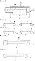
FIG. 1 illustrates an exemplary roll. As illustrated inFIG. 1 , the roll may include bothends 210 which are in contact with asubstrate 101, and acentral portion 220 which is not in contact with thesubstrate 101. A ratio Rc/Re of a diameter Rc of thecentral portion 220 to a diameter Re of each of theends 210 is not particularly limited, but may be controlled to enable thesubstrate 101 to be properly transferred. For example, the ratio Rc/Re may be 0.9 or less, or 0.5 to 0.9. In the structure in which the central portion does not exist, the ratio Rc/Re is 0. - A distance Lc between the both
ends 210, in a case that there is not thecentral portion 220, to a length L of the roll, which is measured in a direction perpendicular to a transferring direction of thesubstrate 101, is not particularly limited, either, as long as theends 210 may be secured so as to properly fix the substrate during the transferring process. For example, the ratio Lc/L may be 0.7 to 0.9. - In one example, a protruding portion may be provided at each of the ends of the roll in order to fix the substrate during the transferring process. Since the substrate is fixed by the protruding portion during the transferring process, the substrate may be prevented from being separated or slid.
- Further, the roll has only the both ends without the central portion.
- For example, the both ends of the roll may be formed to fix the substrate, while applying a tensile force to the substrate in one direction within an angular range of 70° to 110° with respect to the transferring direction of the substrate, e.g., a vertical direction during the transferring process of the substrate. For example, the ends may be formed to be movable while tensing the substrate in the one direction within the angular range of 70° to 110° with respect to the transferring direction of the substrate, e.g., the vertical direction. In another example, patterns of the ends or the protruding portions provided at the ends may be formed so as to transfer and tense the substrate at the same time.
-
FIGS. 2 to 5 are views exemplarily illustrating the above mentioned structures. - For example, as illustrated in
FIG. 2 , the roll may have the structure having only the bothends 210. In this structure, thesubstrate 101 is fixed to protrudingportions 310 of the bothends 210, and the bothends 210 are horizontally moved, and thus thesubstrate 101 may be transferred while being tensed. - The structure in
FIG. 2 may be applied to a roll having thecentral portion 220, as illustrated inFIG. 3 . -
FIG. 4 is a view illustrating another type which may transfer thesubstrate 101 while applying the tensile force to thesubstrate 101. As illustrated inFIG. 4 , theprotruding portion 310 may be formed into a predetermined pattern. In this case, the pattern of theprotruding portion 310 is not particularly limited. For example, the protruding pattern may include a line shape which forms an angle larger than 0° and less than 90° with respect to a movement direction (the transferring direction) of the substrate. The line shape may be, for example, a comb shape, i.e., a shape illustrated inFIG. 4 . -
FIG. 5 is a view illustrating yet another type of the structure. As illustrated inFIG. 5 , even when each of the bothends 210 has a tapered shape, it is possible to embody the structure which may transfer thesubstrate 101 while applying the tensile force to thesubstrate 101. This structure may make an effect in which the both ends 210 pull thesubstrate 101 in both directions during the transferring process of thesubstrate 101. - Further, the exemplary roll may be a roll (hereinafter, called a precursor supplying roll, or a supplying roll) which is used for transferring the substrate, as described above, and installed to supply a precursor to substrate transferred.
- The precursor supplying roll has a precursor supplying unit for supplying the precursor. The precursor supplying roll may have a structure in having only the ends without the central portion. In these structures, a position of the precursor supplying unit is not particularly limited. The precursor supplying unit is provided at an inner side surface of each of the ends.
- In one example, the supplying roll may include the both ends, and the both ends may be installed to be in contact with and transfer the substrate, and the central portion does not exist so as not to be in contact with the substrate during a transferring process of the substrate.
-
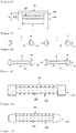
FIG. 6 illustrates an exemplary supplying roll. As illustrated inFIG. 6 , the supplying roll may include both ends 210 which are in contact with asubstrate 101, and acentral portion 220 which is not in contact with thesubstrate 101. In the supplying roll, a ratio Rc/Re of a diameter Rc of thecentral portion 220 to a diameter Re of each of theends 210 is not particularly limited, but may be controlled to enable thesubstrate 101 to be properly transferred and also to secure a sufficient distance for efficiently forming a monolayer on thesubstrate 101 with the supplied precursor. For example, the ratio Rc/Re may be 0.9 or less. In the structure in which the central portion does not exist, the ratio Rc/Re is 0. - A distance Lc between the both ends 210, in a case in which there is not the
central portion 220, to a length L of the supplying roll, which is measured in a direction perpendicular to the transferring direction of thesubstrate 101, is not particularly limited, either, as long as theends 210 may be secured so as to properly fix the substrate during the transferring process. For example, the ratio Lc/L may be 0.7 to 0.9. - When the precursor is a liquid or a gas, a
spraying orifice 230 as the supplying unit may be provided at thecentral portion 220 of the supplying roll so as to spray the precursor to thesubstrate 101, as illustrated inFIG. 6 . For example, the precursor may be injected through a side surface of the supplying roll and then sprayed to thesubstrate 101 through the sprayingorifice 230. Although not illustrated in the drawings, for example, the sprayingorifice 230 may be formed at an inner side surface of each of theends 210, i.e., a side surface of each of theends 210 faced to thecentral portion 220. - The spraying
orifice 230 of the supplying roll may be formed in a well-known manner without any limitation, and, for example, may be formed into a spraying nozzle or the like. For example, the sprayingorifice 230 may be installed at thecentral portion 220 of the supplying roll, as illustrated inFIG. 1 , or at the inner side surface of each of theends 210, although not illustrated in the drawings. InFIG. 6 , the sprayingorifice 230 has a protruding structure, but may have a depressed structure. The number of the sprayingorifices 230 may be properly controlled according to a length of the supplying roll and a surface area to be treated. - A guide roll may have the same structure as the supplying roll, except that the spraying
orifice 230 is not provided. That is, the structure of the supplying roll described in the specification may be also applied to the guide roll or an input and collection unit, except the installation of the spraying orifice. - In one example, a protruding portion may be provided at each of the ends of the supplying roll in order to fix the substrate during the transferring process. Since the substrate is fixed by the protruding portion during the transferring process, the substrate may be prevented from being separated or slid.
- In the structure in which only the both ends are provided without the central portion, the precursor supplying unit may be formed at one of the two inner side surfaces of the both ends or formed at both of them to be faced with each other.
- For example, the both ends of the supplying roll may be formed to fix the substrate, while applying a tensile force to the substrate in one direction within an angular range of about 70° to 110° with respect to the transferring direction of the substrate, e.g., a vertical direction during the transferring process of the substrate. For example, the ends may be formed to be movable while tensing the substrate in the one direction within the angular range of 70° to 110° with respect to the transferring direction of the substrate, e.g., the vertical direction. In another example, patterns of the ends or the protruding portions provided at the ends may be formed so as to transfer and tense the substrate at the same time.
-
FIGS. 7 to 10 are views exemplarily illustrating the above mentioned structures. - For example, as illustrated in
FIG. 7 , the supplying roll may have the structure having only the both ends 210. In this structure, thesubstrate 101 is fixed to protrudingportions 310 of the both ends 210, and the both ends 210 are horizontally moved, and thus thesubstrate 101 may be transferred while being tensed. - The structure in
FIG. 7 may be applied to a supplying roll having thecentral portion 220, as illustrated inFIG 8 . -
FIG 9 is a view illustrating another type which may transfer thesubstrate 101 while applying the tensile force to thesubstrate 101. As illustrated inFIG. 9 , the protrudingportion 310 may be formed into a predetermined pattern. In this case, the pattern of the protrudingportion 310 is not particularly limited. For example, the protruding pattern may have a comb shape, i.e., a line shape which forms an angle larger than 0° and less than 90° with respect to the transferring direction of thesubstrate 101 in an outside direction of the supplying roll so as to transfer thesubstrate 101 while applying the tensile force to thesubstrate 101, as illustrated inFIG. 9 . -
FIG. 10 is a view illustrating yet another type of the supplying roll. As illustrated inFIG. 10 , even when each of the both ends 210 has a tapered shape, it is possible to embody the structure which may transfer thesubstrate 101 while applying the tensile force to thesubstrate 101. This structure may make an effect in which the both ends 210 pull thesubstrate 101 in both directions during the transferring process of thesubstrate 101. - Also, the present invention relates to a film forming apparatus. The film forming apparatus may include a transferring unit and a treating region.
- The transferring unit may include a supplying roll for supplying a substrate, one or more guide rolls for transferring the substrate, and a collecting roll for collecting the substrate. At least one of the guide rolls may be a roll having the above-mentions structures.
- The treating region is a region in which the substrate is introduced by the transferring unit and a treatment for forming a film is carried out. For example, the treating region may be a general chamber. As described later, when a layer of the precursor is formed on a surface of the substrate in the treating region, the treating region may be formed to receive the precursor. The precursor as a term used in the specification may include all kinds of materials which may form the film, and each of which itself may form the film, or each of which may be applied to the surface of the substrate first and then may form the film by itself or through a reaction with other materials. A state of the precursor is not particularly limited, and may be a gas, a liquid, or a solid (for example, a fine powder).
- A mechanism for forming the precursor layer in the treating region is not particularly limited. For example, a method of forming the film, such as an atomic layer deposition (ALD), a CVD, and a sputtering, is already known variously. In a mechanism for forming the film in first and second regions, the mechanism may be selected properly according to employed one out of the above methods.
- In one example, the treating region may be disposed to form the film in the ALD.
- The exemplary treating region may include at least two regions (hereinafter, called a first region and a second region). Each of the first and second regions may have at least one or more passages, for example, flow-restricting passages. The flow-restricting passage as a term used in the specification may mean a passage through which the substrate may be moved, but the precursor in each region is prevented from being leaked to an outside or another region. A forming method of the passage will be described later. The each region may be disposed to deposit the precursor on the surface of the substrate introduced through the flow-restricting passages and thus form a layer.
- At least one guide roll of the transferring unit may be provided in each of the first and second regions. The guide roll may form a path which enables the substrate to pass at least once through the first and second regions through the passage, e.g., the flow-restricting passage.
- In the film forming apparatus, at least one of the guide rolls provided in the first and second regions may be a precursor supplying roll which is installed to supply the precursor to the substrate. For example, if the supplying roll is disposed in the first region, a first precursor may be supplied to the substrate by the supplying roll, while the substrate passes through the first region, and a first precursor layer, e.g., a first monolayer may be formed. If the supplying roll is disposed in the second region, a second precursor layer, e.g., a second monolayer may be formed on the surface of the substrate, while the substrate passes through the second region. The supplying roll may be provided in both of the first and second regions. Further, in the region in which the supplying roll is not provided, another well-known unit for supplying the precursor to the corresponding region may be provided. This manner may be proper to, for example, the ALD, and a desired film may be formed on the substrate through a process in which the first and second monolayers or additional another monolayers are repeatedly formed on the substrate by the supplying roll or another unit, as described above. The first and second precursors may be the same or different kinds from each other, and if necessary, the process of forming the first and second monolayers may be repeated multiple times in order to achieve a desired thickness. Further, the film forming apparatus may include a third region in which a third monolayer is formed by a third precursor, or a purging process is carried out by an inert gas.
- In the film forming apparatus, the transferring unit may further include an input unit for supplying the substrate to the film forming apparatus. The transferring unit may further include a collection unit for collecting the treated substrate. A kind of each of the input unit and the collection unit is not particularly limited. For example, the input unit may be an unwinding roll which unwinds and supplies the substrate wound in a roll type, and the collection unit may be a rewinding roll which rewinds and collects the substrate.
-
FIG. 11 is a schematic diagram of an exemplary film forming apparatus. - As illustrated in
FIG. 11 , the film forming apparatus may include afirst region 131 and asecond region 132. The transferring unit may include at least oneguide roll 120 disposed in each of the first andsecond regions collection unit 140 for collecting the treatedsubstrate 101, and aninput unit 110 for supplying thesubstrate 101. In the drawing, theinput unit 110 and thecollection unit 140 are disposed in the first andsecond regions input unit 110 and thecollection unit 140 may be disposed outside the first andsecond regions second regions wall 150 so as to prevent the precursor in each region from being diffused or leaked to another region. Thewall 150 has apassage 160, for example the flow-restricting passage, and thesubstrate 101 may be moved through thepassage 160. Anexhausting unit 170 may be provided in each of the first andsecond regions exhausting unit 170. - In the film forming apparatus, the
input unit 110 serves to introduce thesubstrate 101 into the apparatus. Theinput unit 110 may be, for example, the unwinding roll. Thesubstrate 101 introduced by theinput unit 110 is treated while passing through each of the first andsecond regions collection unit 140, for example, the rewinding roll. - At least one of the guide rolls 120 of a transferring unit may be the above-mentioned roll, i.e., the roll having the structure in which the both ends has a larger diameter than the central portion so that only the both ends are in contact with the substrate in the direction perpendicular to the transferring direction of the
substrate 101 during the transferring process of thesubstrate 101, or may be the precursor supplying roll installed to supply the precursor to thesubstrate 101. -
FIG. 12 is a view illustrating another type of the film forming apparatus including the above-mentioned roll. An upper side ofFIG. 12 is a side view of the film forming apparatus, and a lower side thereof is a front view of the film forming apparatus. - In one example of
FIG. 12 , the first andsecond regions substrate 101 passes through an upper portion of each of the first andsecond regions region substrate 101 is formed by the guide rolls, and may be formed by the passage in the apparatus, e.g., the flow-restricting passage through which the substrate may be moved. In this structure, the precursor may be exhausted from a side surface of eachregion FIG. 12 . InFIG 12 , only the first andsecond regions substrate 101 may pass through the first andsecond regions second regions - The film forming apparatus may further include the third region. The third region may be, for example, a region through which the inert gas required in the purging process of the ALD is introduced, or the precursor which is the same as or different from that introduced into the
first region 131 and/or thesecond region 132 is introduced. If there is the third region, the third region may be connected with thefirst region 131 and/or thesecond region 132 through the flow-restricting passage, and the transferring unit may be installed to enable the substrate to pass through the first and second regions in turn via the third region. For example, the substrate may pass through the first region, the third region, and the second region in turn, or may pass through the second region, the third region, and the first region in turn by the transferring unit. -
FIG. 13 is a view exemplarily illustrating a state in which athird region 701 is additionally provided in the film forming apparatus ofFIG. 11 , and thus the description ofFIG. 11 except the existence of thethird region 701 may be applied similarly. InFIG. 13 , a separate roll is not provided in thethird region 701, but if necessary, the supplying roll, the guide roll, or the like may be provided in thethird region 701, as illustrated inFIG. 15 . In the example illustrated inFIG. 13 , a plurality ofthird regions 701 may be provided. The plurality ofthird regions 701 may be provided between the first andsecond regions third regions 701 may be partitioned by thewall 150 having each passage, e.g., each flow-restrictingpassage 160, and thesubstrate 101 may pass through thefirst region 131 and the plurality ofthird regions 701 through each flow-restrictingpassage 160, in turn, and then may be introduced into thesecond region 132.FIG 14 is a view illustrating an example in which the plurality of third regions 701-1 to 701-3 are provided, as described above. When the plurality of third regions 701-1 to 701-3 are provided, a gas introduced in each of the third regions 701-1 to 701-3 may be the same as or different from each other. -
FIG. 15 is a view exemplarily illustrating a state in which twothird regions FIG. 11 . The inert gas, or the precursor which is the same as or different from that in the first and/or second region may be introduced into the twothird regions third regions - The transferring unit of the film forming apparatus, for example, the guide rolls may be installed to enable the substrate to pass multiple times through the first and second regions. When the third region is provided, the transferring unit, for example, the guide rolls may be installed to enable the substrate to pass multiple times through the first and second regions via the third region every time.
FIG. 16 is a view illustrating the transferring unit which is formed to enable the substrate to pass multiple times through the first andsecond regions third region 701 every time (i.e., according to the order of the first region → the third region → the second region → the third region → the first region → the third region → the second region).FIG 16 illustrates the case that thethird region 701 is provided, but thethird region 701 may be not provided. In another example, the plurality of third regions 701-1 to 701-3 may be provided, as illustrated inFIG. 17 . - As illustrated in
FIG. 16 , the transferring unit may include a plurality of first guide rolls (120-1 and so on) provided in thefirst region 131 and a plurality of second guide rolls (120-2 and so on) provided in thesecond region 132. At least a part (e.g., 120-1 in the drawing) of the first guide rolls may be formed to change the path of thesubstrate 101 toward thesecond region 132, and at least a part (e.g., 120-2 in the drawing) of the second guide rolls may be formed to change the path of thesubstrate 101 toward thefirst region 131. - In the above-mentioned film forming apparatus, the substrate may pass through each region by the transferring unit and, in the corresponding region, the precursor may be deposited so as to form the monolayer, or the purging process may be performed. The precursor may be supplied by the above-mentioned precursor supplying roll. Also, if necessary, the film forming apparatus may include another supplying unit as well as the precursor supplying roll. Therefore, the precursor may be introduced into each region by the other supplying unit as well as the precursor supplying roll. The other supplying unit may include a precursor source installed inside or outside each region, and may further include a pipe, a pump, a valve, a tank, and other well-known unit. Further, for example, in a case in which another region like the third region other than the first and second regions is provided and the supplying roll is not provided in the corresponding region, the precursor or the inert gas may be introduced in the corresponding region by the other supplying unit.
- In the film forming apparatus, each region may be a chamber which may control an internal pressure through an exhausting process by the exhausting unit or an introduction pressure of the precursor or the inert gas. The chamber may interface with other processing module or equipment for controlling an operation or the like.
- In the film forming apparatus, it is necessary to restrict the precursor in each region from being moved into other regions in order to prevent an undesirable reaction caused by mixing the non-deposited precursor on the substrate with a gas in other regions, for example, a non-ALD reaction. Thus, the regions may be connected to each other through the flow-restricting passage, or may be adapted to enable the internal pressure to be further controlled. A method of forming the flow-restricting passage is not particularly limited, and a well-known method may be applied. For example, each passage may be a slit which is slightly thicker and wider than a thickness and width of the substrate passing through the passage. The passage may be formed to allow only a very small clearance when the substrate passes through the passage but enable the substrate to pass through the passage without any scratches from each surface of the passage. For example, the clearance may be defined within an extent between a few microns and a few millimeters. Further, the passage may be formed to include an elongated tunnel through which the substrate may pass, and if necessary, may further include a wiper for further limiting a flow of gas through the passage. Also, the passage may be an extended long and narrow passage, and the inert gas injected into the third region or the like may be directly injected into the passage at middle portions of the first and second regions and thus may assist prevention of moving and mixing of the precursor.
- In order to prevent the mixing of the precursor, a pressure difference may be formed between the regions. For example, as illustrated in
FIG. 13 or16 , if thethird region 701 is provided between the first andsecond regions third region 701 with a larger pressure than that in each of the first andsecond regions - Furthermore, the present invention relates to a film forming method. For example, the film forming method may be the ALD. For example, this method may be carried out using the above-mentioned film forming apparatus. For example, while the substrate is transferred along the path formed through the passage by the guide rolls of the film forming apparatus, the first monolayer may be formed on the substrate in the first region by supplying the precursor using the precursor supplying roll or another supplying unit, and the second monolayer may be formed on the substrate in the second region by supplying the precursor using the precursor supplying roll or another supplying unit, whereby a film may be formed on the substrate. This process may be repeated twice or more in order to obtain a desired thickness of the film, and if necessary, one or more third regions may be provided so as to perform the purging process between the processes of forming the first and second monolayers, or form a third monolayer made of a different material from those of the first and second monolayers.
- A kind of the substrate used in the film forming method is not particularly limited, and may be formed of, for example, glass, a plastic film, a metallic web, a fibrous film, or the like. Further, a kind of the film formed on the substrate by the film forming method may include all of well-known films formed by the ALD or predicted films to be formed by the ALD, for example, a barrier layer, a conductive layer, a dielectric layer, an insulating layer, an emissive layer, an electron transport layer, an electron injection layer, a hole injection layer, a hole transport layer, or the like.
- Also, a kind of the precursor used for forming the film is not particularly limited and, for example, may include all of well-known kinds which may applied to the ALD and may form the above-mentioned kinds of films.
Claims (17)
- A roll used as a guide roll of a film forming apparatus which comprises a transferring unit including one or more guide rolls installed to transfer a substrate; and a treating region installed to form a film on a surface of the substrate transferred by the transferring unit,
wherein the roll comprises a supplying unit configured to supply a precursor to the substrate during a transferring process of the substrate,
wherein the roll comprising the supplying unit is disposed in the treating region,
wherein the roll has a structure in which a central portion does not exist so as to be in contact with both ends of the substrate in a direction perpendicular to the transferring direction of the substrate, but not in contact with other portions of the substrate, and
the supplying unit is formed at an inner side surface of the end. - The roll of claim 1, wherein a fixing unit configured to fix the substrate during the transferring process of the substrate is provided at the end.
- The roll of claim 2, wherein the end is installed to apply a tensile force to the substrate and fix the substrate.
- The roll of claim 1, wherein the end is formed to be movable in one direction within an angular range of 70° to 110° with respect to the transferring direction of the substrate.
- The roll of claim 1, wherein the end has a protruding pattern which is formed to apply a tensile force to the substrate during the transferring process of the substrate.
- The roll of claim 5, wherein the protruding pattern comprises a line shape which forms an angle larger than 0° and less than 90° with respect to a transferring direction of the substrate.
- The roll of claim 1, wherein the precursor is injected through a side surface, and the injected precursor is sprayed through a spraying orifice.
- A film forming apparatus comprising:a transferring unit including one or more guide rolls installed to transfer a substrate; anda treating region installed to form a film on a surface of the substrate transferred by the transferring unit,wherein at least one of the guide rolls is the roll of claim 1.
- The apparatus of claim 8, wherein the treating region is installed to form the film on the substrate through an ALD manner.
- The apparatus of claim 8, wherein the treating region comprises first and second regions which are respectively installed to form a layer of a precursor on the substrate, and
one or more guide rolls are provided in each of the first and second regions and thus form a path through which the substrate passes through the first and second regions in turn. - The apparatus of claim 10, further comprising an exhausting unit configured to exhaust the precursor in the first or second region.
- The apparatus of claim 10, wherein a transferring unit is installed to enable the substrate to pass multiple times through the first and second regions.
- The apparatus of claim 10, further comprising a third region which is installed to enable an inert gas or the precursor to be supplied therein,
wherein the third region is connected with the first or second region, and the transferring unit is formed to enable the substrate to pass through the first region, the third region, and the second region in turn, or the second region, the third region, and the first region in turn. - The apparatus of claim 13, wherein a transferring unit is installed to enable the substrate to pass multiple times through the first and second regions via the third region every time.
- The apparatus of claim 10, wherein a transferring unit comprises a plurality of first guide rolls provided in the first region and a plurality of second guide rolls provided in the second region, and
at least a part of the first guide rolls is formed to change the path of the substrate toward the second region, and at least a part of the second guide rolls is formed to change the path of the substrate toward the first region. - A method of forming a film on a substrate using the film forming apparatus of claim 8.
- The method of claim 16, wherein the substrate is formed of a plastic film, a metallic web, or a fibrous film.
Applications Claiming Priority (2)
| Application Number | Priority Date | Filing Date | Title |
|---|---|---|---|
| KR20120138317 | 2012-11-30 | ||
| PCT/KR2013/011099 WO2014084700A1 (en) | 2012-11-30 | 2013-12-02 | Roll |
Publications (3)
| Publication Number | Publication Date |
|---|---|
| EP2940182A1 EP2940182A1 (en) | 2015-11-04 |
| EP2940182A4 EP2940182A4 (en) | 2016-07-27 |
| EP2940182B1 true EP2940182B1 (en) | 2020-05-20 |
Family
ID=51125305
Family Applications (1)
| Application Number | Title | Priority Date | Filing Date |
|---|---|---|---|
| EP13857783.8A Active EP2940182B1 (en) | 2012-11-30 | 2013-12-02 | Roll |
Country Status (7)
| Country | Link |
|---|---|
| US (1) | US10364499B2 (en) |
| EP (1) | EP2940182B1 (en) |
| JP (1) | JP6066153B2 (en) |
| KR (3) | KR101548820B1 (en) |
| CN (1) | CN104812936B (en) |
| TW (1) | TWI587931B (en) |
| WO (1) | WO2014084700A1 (en) |
Families Citing this family (3)
| Publication number | Priority date | Publication date | Assignee | Title |
|---|---|---|---|---|
| KR101667139B1 (en) * | 2015-03-03 | 2016-10-24 | 주식회사 엘지화학 | Film forming apparatus |
| JP6697706B2 (en) * | 2015-12-07 | 2020-05-27 | 凸版印刷株式会社 | Atomic layer deposition equipment |
| EP3436620A1 (en) * | 2016-04-01 | 2019-02-06 | 3M Innovative Properties Company | Roll-to-roll atomic layer deposition apparatus and method |
Family Cites Families (27)
| Publication number | Priority date | Publication date | Assignee | Title |
|---|---|---|---|---|
| JPS5632484B2 (en) * | 1974-12-27 | 1981-07-28 | ||
| EP0122092A3 (en) | 1983-04-06 | 1985-07-10 | General Engineering Radcliffe Limited | Vacuum coating apparatus |
| JPS61174053A (en) * | 1985-01-25 | 1986-08-05 | Sando Iron Works Co Ltd | Continuous unfurling cloth transfer device for canvas |
| JPH0312840U (en) * | 1989-06-20 | 1991-02-08 | ||
| US6138885A (en) * | 1997-11-03 | 2000-10-31 | Gerber Scientific Products, Inc. | Web having alignment indicia and an associated web feeding and working apparatus |
| JP3844274B2 (en) * | 1998-06-25 | 2006-11-08 | 独立行政法人産業技術総合研究所 | Plasma CVD apparatus and plasma CVD method |
| KR100492769B1 (en) * | 2001-05-17 | 2005-06-07 | 주식회사 엘지이아이 | An apparatus for continuous plasma polymerizing with a vertical chamber |
| FR2877518B1 (en) * | 2004-11-02 | 2007-02-09 | Airbus France Sas | RADIO FREQUENCY COMMUNICATION SYSTEM FOR AIRCRAFT |
| JP2007009301A (en) * | 2005-07-04 | 2007-01-18 | Sumitomo Metal Mining Co Ltd | Method for producing copper-coated polyimide substrate |
| ATE507320T1 (en) * | 2006-03-26 | 2011-05-15 | Lotus Applied Technology Llc | ATOMIC LAYER DEPOSITION SYSTEM AND METHOD FOR COATING FLEXIBLE SUBSTRATES |
| US20070281089A1 (en) * | 2006-06-05 | 2007-12-06 | General Electric Company | Systems and methods for roll-to-roll atomic layer deposition on continuously fed objects |
| WO2008139834A1 (en) | 2007-05-14 | 2008-11-20 | Ulvac, Inc. | Film conveying device and winding-type vacuum film-forming method |
| US20090018896A1 (en) * | 2007-07-13 | 2009-01-15 | Digital River, Inc. | Scaled Subscriber Profile Groups for Emarketers |
| JP2009179427A (en) * | 2008-01-30 | 2009-08-13 | Fujifilm Corp | Conveying device and vacuum film deposition device |
| DE102008000600B4 (en) * | 2008-03-11 | 2010-05-12 | Chemetall Gmbh | Process for coating metallic surfaces with a passivating agent, the passivating agent, the coating produced therewith and their use |
| JP2009234713A (en) | 2008-03-27 | 2009-10-15 | Toray Ind Inc | Cloth guider with groove |
| WO2009122836A1 (en) * | 2008-03-31 | 2009-10-08 | 富士電機システムズ株式会社 | Production equipment and method of thin-film laminate |
| JP5146067B2 (en) * | 2008-04-15 | 2013-02-20 | コニカミノルタホールディングス株式会社 | Guide roll mechanism, vacuum film forming apparatus using the same, and organic electroluminescence element manufacturing method |
| JP5081712B2 (en) * | 2008-05-02 | 2012-11-28 | 富士フイルム株式会社 | Deposition equipment |
| JP4786772B2 (en) * | 2010-01-26 | 2011-10-05 | パナソニック株式会社 | Thin film manufacturing apparatus, thin film manufacturing method, and substrate transfer roller |
| JP5385178B2 (en) | 2010-02-26 | 2014-01-08 | 富士フイルム株式会社 | Flexible film transport apparatus and barrier film manufacturing method |
| CN102183198B (en) * | 2011-03-15 | 2012-08-22 | 清华大学 | Device for measuring film thickness of silicon slice |
| JP2012201900A (en) * | 2011-03-23 | 2012-10-22 | Toppan Printing Co Ltd | Film deposition apparatus |
| JP5724504B2 (en) | 2011-03-23 | 2015-05-27 | 凸版印刷株式会社 | Rotating drum and atomic layer deposition method film forming apparatus in atomic layer deposition method film forming apparatus |
| CN103459665B (en) * | 2011-03-29 | 2017-02-22 | 凸版印刷株式会社 | Rolled film formation apparatus |
| US20140023796A1 (en) | 2011-03-31 | 2014-01-23 | Toray Industries, Inc. | Plasma cvd apparatus, plasma cvd method, reactive sputtering apparatus, and reactive sputtering method |
| KR101788171B1 (en) * | 2011-08-16 | 2017-10-20 | 삼성전자주식회사 | System for roll to roll printing |
-
2013
- 2013-12-02 KR KR1020130148680A patent/KR101548820B1/en active IP Right Grant
- 2013-12-02 EP EP13857783.8A patent/EP2940182B1/en active Active
- 2013-12-02 JP JP2015545377A patent/JP6066153B2/en active Active
- 2013-12-02 US US14/646,646 patent/US10364499B2/en active Active
- 2013-12-02 TW TW102144220A patent/TWI587931B/en active
- 2013-12-02 KR KR1020130148681A patent/KR101554073B1/en active IP Right Grant
- 2013-12-02 WO PCT/KR2013/011099 patent/WO2014084700A1/en active Application Filing
- 2013-12-02 CN CN201380062324.1A patent/CN104812936B/en active Active
- 2013-12-02 KR KR1020130148682A patent/KR101554074B1/en active IP Right Grant
Non-Patent Citations (1)
| Title |
|---|
| None * |
Also Published As
| Publication number | Publication date |
|---|---|
| US10364499B2 (en) | 2019-07-30 |
| TW201436886A (en) | 2014-10-01 |
| EP2940182A4 (en) | 2016-07-27 |
| KR101548820B1 (en) | 2015-08-31 |
| KR20140125276A (en) | 2014-10-28 |
| KR101554074B1 (en) | 2015-09-17 |
| KR101554073B1 (en) | 2015-09-17 |
| EP2940182A1 (en) | 2015-11-04 |
| KR20140125277A (en) | 2014-10-28 |
| CN104812936B (en) | 2017-04-12 |
| CN104812936A (en) | 2015-07-29 |
| WO2014084700A1 (en) | 2014-06-05 |
| JP2016505712A (en) | 2016-02-25 |
| JP6066153B2 (en) | 2017-01-25 |
| KR20140070487A (en) | 2014-06-10 |
| US20150337439A1 (en) | 2015-11-26 |
| TWI587931B (en) | 2017-06-21 |
Similar Documents
| Publication | Publication Date | Title |
|---|---|---|
| EP2940182B1 (en) | Roll | |
| EP2930255B1 (en) | Film formation apparatus | |
| US20090229523A1 (en) | Film depositing apparatus | |
| US7820247B2 (en) | Curtain-type coater | |
| KR101667139B1 (en) | Film forming apparatus | |
| CN112243465B (en) | Atomic layer deposition apparatus | |
| KR100823182B1 (en) | Slit nozzle for spraying liquid | |
| US20140134341A1 (en) | Deposition apparatus and method of depositing thin layer using the same | |
| KR101610783B1 (en) | Apparatus for dealing flexible substrate | |
| KR102204306B1 (en) | Active slot-die coater | |
| KR20200104228A (en) | Coating apparatus and manufacturing method of coating member | |
| US20120034386A1 (en) | Apparatus and method for coating | |
| JPH07102354A (en) | Coating weight controlling device in hot-dip metal plating | |
| KR20150047266A (en) | Atomic layer deposition apparatus and method of depositing an atomic layer using the same | |
| KR20200089232A (en) | Apparatus of Atomic Layer Deposition | |
| US20140356543A1 (en) | Spray Nozzle, Spraying Device Having the Spray Nozzle and Method for Spraying | |
| JP2019089027A (en) | Electrospray device |
Legal Events
| Date | Code | Title | Description |
|---|---|---|---|
| PUAI | Public reference made under article 153(3) epc to a published international application that has entered the european phase |
Free format text: ORIGINAL CODE: 0009012 |
|
| 17P | Request for examination filed |
Effective date: 20150521 |
|
| AK | Designated contracting states |
Kind code of ref document: A1 Designated state(s): AL AT BE BG CH CY CZ DE DK EE ES FI FR GB GR HR HU IE IS IT LI LT LU LV MC MK MT NL NO PL PT RO RS SE SI SK SM TR |
|
| AX | Request for extension of the european patent |
Extension state: BA ME |
|
| DAX | Request for extension of the european patent (deleted) | ||
| A4 | Supplementary search report drawn up and despatched |
Effective date: 20160628 |
|
| RIC1 | Information provided on ipc code assigned before grant |
Ipc: C23C 16/44 20060101AFI20160622BHEP Ipc: H01L 21/205 20060101ALI20160622BHEP Ipc: C23C 16/458 20060101ALI20160622BHEP Ipc: B65H 20/02 20060101ALI20160622BHEP Ipc: B65H 27/00 20060101ALI20160622BHEP |
|
| STAA | Information on the status of an ep patent application or granted ep patent |
Free format text: STATUS: EXAMINATION IS IN PROGRESS |
|
| 17Q | First examination report despatched |
Effective date: 20180530 |
|
| GRAP | Despatch of communication of intention to grant a patent |
Free format text: ORIGINAL CODE: EPIDOSNIGR1 |
|
| STAA | Information on the status of an ep patent application or granted ep patent |
Free format text: STATUS: GRANT OF PATENT IS INTENDED |
|
| RIC1 | Information provided on ipc code assigned before grant |
Ipc: B65H 27/00 20060101ALI20191108BHEP Ipc: C23C 16/458 20060101ALI20191108BHEP Ipc: C23C 16/44 20060101AFI20191108BHEP Ipc: H01L 21/677 20060101ALI20191108BHEP Ipc: H01L 21/205 20060101ALI20191108BHEP Ipc: B65H 20/02 20060101ALI20191108BHEP Ipc: H01L 21/67 20060101ALI20191108BHEP Ipc: C23C 16/54 20060101ALI20191108BHEP Ipc: B65H 23/025 20060101ALI20191108BHEP |
|
| INTG | Intention to grant announced |
Effective date: 20191217 |
|
| GRAS | Grant fee paid |
Free format text: ORIGINAL CODE: EPIDOSNIGR3 |
|
| GRAA | (expected) grant |
Free format text: ORIGINAL CODE: 0009210 |
|
| STAA | Information on the status of an ep patent application or granted ep patent |
Free format text: STATUS: THE PATENT HAS BEEN GRANTED |
|
| AK | Designated contracting states |
Kind code of ref document: B1 Designated state(s): AL AT BE BG CH CY CZ DE DK EE ES FI FR GB GR HR HU IE IS IT LI LT LU LV MC MK MT NL NO PL PT RO RS SE SI SK SM TR |
|
| REG | Reference to a national code |
Ref country code: GB Ref legal event code: FG4D |
|
| REG | Reference to a national code |
Ref country code: CH Ref legal event code: EP |
|
| REG | Reference to a national code |
Ref country code: DE Ref legal event code: R096 Ref document number: 602013069321 Country of ref document: DE |
|
| REG | Reference to a national code |
Ref country code: AT Ref legal event code: REF Ref document number: 1272653 Country of ref document: AT Kind code of ref document: T Effective date: 20200615 |
|
| REG | Reference to a national code |
Ref country code: LT Ref legal event code: MG4D |
|
| REG | Reference to a national code |
Ref country code: NL Ref legal event code: MP Effective date: 20200520 |
|
| PG25 | Lapsed in a contracting state [announced via postgrant information from national office to epo] |
Ref country code: GR Free format text: LAPSE BECAUSE OF FAILURE TO SUBMIT A TRANSLATION OF THE DESCRIPTION OR TO PAY THE FEE WITHIN THE PRESCRIBED TIME-LIMIT Effective date: 20200821 Ref country code: NO Free format text: LAPSE BECAUSE OF FAILURE TO SUBMIT A TRANSLATION OF THE DESCRIPTION OR TO PAY THE FEE WITHIN THE PRESCRIBED TIME-LIMIT Effective date: 20200820 Ref country code: FI Free format text: LAPSE BECAUSE OF FAILURE TO SUBMIT A TRANSLATION OF THE DESCRIPTION OR TO PAY THE FEE WITHIN THE PRESCRIBED TIME-LIMIT Effective date: 20200520 Ref country code: IS Free format text: LAPSE BECAUSE OF FAILURE TO SUBMIT A TRANSLATION OF THE DESCRIPTION OR TO PAY THE FEE WITHIN THE PRESCRIBED TIME-LIMIT Effective date: 20200920 Ref country code: PT Free format text: LAPSE BECAUSE OF FAILURE TO SUBMIT A TRANSLATION OF THE DESCRIPTION OR TO PAY THE FEE WITHIN THE PRESCRIBED TIME-LIMIT Effective date: 20200921 Ref country code: LT Free format text: LAPSE BECAUSE OF FAILURE TO SUBMIT A TRANSLATION OF THE DESCRIPTION OR TO PAY THE FEE WITHIN THE PRESCRIBED TIME-LIMIT Effective date: 20200520 Ref country code: SE Free format text: LAPSE BECAUSE OF FAILURE TO SUBMIT A TRANSLATION OF THE DESCRIPTION OR TO PAY THE FEE WITHIN THE PRESCRIBED TIME-LIMIT Effective date: 20200520 |
|
| PG25 | Lapsed in a contracting state [announced via postgrant information from national office to epo] |
Ref country code: HR Free format text: LAPSE BECAUSE OF FAILURE TO SUBMIT A TRANSLATION OF THE DESCRIPTION OR TO PAY THE FEE WITHIN THE PRESCRIBED TIME-LIMIT Effective date: 20200520 Ref country code: BG Free format text: LAPSE BECAUSE OF FAILURE TO SUBMIT A TRANSLATION OF THE DESCRIPTION OR TO PAY THE FEE WITHIN THE PRESCRIBED TIME-LIMIT Effective date: 20200820 Ref country code: RS Free format text: LAPSE BECAUSE OF FAILURE TO SUBMIT A TRANSLATION OF THE DESCRIPTION OR TO PAY THE FEE WITHIN THE PRESCRIBED TIME-LIMIT Effective date: 20200520 Ref country code: LV Free format text: LAPSE BECAUSE OF FAILURE TO SUBMIT A TRANSLATION OF THE DESCRIPTION OR TO PAY THE FEE WITHIN THE PRESCRIBED TIME-LIMIT Effective date: 20200520 |
|
| REG | Reference to a national code |
Ref country code: AT Ref legal event code: MK05 Ref document number: 1272653 Country of ref document: AT Kind code of ref document: T Effective date: 20200520 |
|
| PG25 | Lapsed in a contracting state [announced via postgrant information from national office to epo] |
Ref country code: AL Free format text: LAPSE BECAUSE OF FAILURE TO SUBMIT A TRANSLATION OF THE DESCRIPTION OR TO PAY THE FEE WITHIN THE PRESCRIBED TIME-LIMIT Effective date: 20200520 Ref country code: NL Free format text: LAPSE BECAUSE OF FAILURE TO SUBMIT A TRANSLATION OF THE DESCRIPTION OR TO PAY THE FEE WITHIN THE PRESCRIBED TIME-LIMIT Effective date: 20200520 |
|
| PG25 | Lapsed in a contracting state [announced via postgrant information from national office to epo] |
Ref country code: DK Free format text: LAPSE BECAUSE OF FAILURE TO SUBMIT A TRANSLATION OF THE DESCRIPTION OR TO PAY THE FEE WITHIN THE PRESCRIBED TIME-LIMIT Effective date: 20200520 Ref country code: ES Free format text: LAPSE BECAUSE OF FAILURE TO SUBMIT A TRANSLATION OF THE DESCRIPTION OR TO PAY THE FEE WITHIN THE PRESCRIBED TIME-LIMIT Effective date: 20200520 Ref country code: AT Free format text: LAPSE BECAUSE OF FAILURE TO SUBMIT A TRANSLATION OF THE DESCRIPTION OR TO PAY THE FEE WITHIN THE PRESCRIBED TIME-LIMIT Effective date: 20200520 Ref country code: SM Free format text: LAPSE BECAUSE OF FAILURE TO SUBMIT A TRANSLATION OF THE DESCRIPTION OR TO PAY THE FEE WITHIN THE PRESCRIBED TIME-LIMIT Effective date: 20200520 Ref country code: EE Free format text: LAPSE BECAUSE OF FAILURE TO SUBMIT A TRANSLATION OF THE DESCRIPTION OR TO PAY THE FEE WITHIN THE PRESCRIBED TIME-LIMIT Effective date: 20200520 Ref country code: CZ Free format text: LAPSE BECAUSE OF FAILURE TO SUBMIT A TRANSLATION OF THE DESCRIPTION OR TO PAY THE FEE WITHIN THE PRESCRIBED TIME-LIMIT Effective date: 20200520 Ref country code: IT Free format text: LAPSE BECAUSE OF FAILURE TO SUBMIT A TRANSLATION OF THE DESCRIPTION OR TO PAY THE FEE WITHIN THE PRESCRIBED TIME-LIMIT Effective date: 20200520 Ref country code: RO Free format text: LAPSE BECAUSE OF FAILURE TO SUBMIT A TRANSLATION OF THE DESCRIPTION OR TO PAY THE FEE WITHIN THE PRESCRIBED TIME-LIMIT Effective date: 20200520 |
|
| REG | Reference to a national code |
Ref country code: DE Ref legal event code: R097 Ref document number: 602013069321 Country of ref document: DE |
|
| PG25 | Lapsed in a contracting state [announced via postgrant information from national office to epo] |
Ref country code: PL Free format text: LAPSE BECAUSE OF FAILURE TO SUBMIT A TRANSLATION OF THE DESCRIPTION OR TO PAY THE FEE WITHIN THE PRESCRIBED TIME-LIMIT Effective date: 20200520 Ref country code: SK Free format text: LAPSE BECAUSE OF FAILURE TO SUBMIT A TRANSLATION OF THE DESCRIPTION OR TO PAY THE FEE WITHIN THE PRESCRIBED TIME-LIMIT Effective date: 20200520 |
|
| PLBE | No opposition filed within time limit |
Free format text: ORIGINAL CODE: 0009261 |
|
| STAA | Information on the status of an ep patent application or granted ep patent |
Free format text: STATUS: NO OPPOSITION FILED WITHIN TIME LIMIT |
|
| 26N | No opposition filed |
Effective date: 20210223 |
|
| PG25 | Lapsed in a contracting state [announced via postgrant information from national office to epo] |
Ref country code: SI Free format text: LAPSE BECAUSE OF FAILURE TO SUBMIT A TRANSLATION OF THE DESCRIPTION OR TO PAY THE FEE WITHIN THE PRESCRIBED TIME-LIMIT Effective date: 20200520 |
|
| REG | Reference to a national code |
Ref country code: CH Ref legal event code: PL |
|
| PG25 | Lapsed in a contracting state [announced via postgrant information from national office to epo] |
Ref country code: MC Free format text: LAPSE BECAUSE OF FAILURE TO SUBMIT A TRANSLATION OF THE DESCRIPTION OR TO PAY THE FEE WITHIN THE PRESCRIBED TIME-LIMIT Effective date: 20200520 |
|
| REG | Reference to a national code |
Ref country code: BE Ref legal event code: MM Effective date: 20201231 |
|
| PG25 | Lapsed in a contracting state [announced via postgrant information from national office to epo] |
Ref country code: LU Free format text: LAPSE BECAUSE OF NON-PAYMENT OF DUE FEES Effective date: 20201202 Ref country code: IE Free format text: LAPSE BECAUSE OF NON-PAYMENT OF DUE FEES Effective date: 20201202 |
|
| PG25 | Lapsed in a contracting state [announced via postgrant information from national office to epo] |
Ref country code: LI Free format text: LAPSE BECAUSE OF NON-PAYMENT OF DUE FEES Effective date: 20201231 Ref country code: CH Free format text: LAPSE BECAUSE OF NON-PAYMENT OF DUE FEES Effective date: 20201231 |
|
| PG25 | Lapsed in a contracting state [announced via postgrant information from national office to epo] |
Ref country code: TR Free format text: LAPSE BECAUSE OF FAILURE TO SUBMIT A TRANSLATION OF THE DESCRIPTION OR TO PAY THE FEE WITHIN THE PRESCRIBED TIME-LIMIT Effective date: 20200520 Ref country code: MT Free format text: LAPSE BECAUSE OF FAILURE TO SUBMIT A TRANSLATION OF THE DESCRIPTION OR TO PAY THE FEE WITHIN THE PRESCRIBED TIME-LIMIT Effective date: 20200520 Ref country code: CY Free format text: LAPSE BECAUSE OF FAILURE TO SUBMIT A TRANSLATION OF THE DESCRIPTION OR TO PAY THE FEE WITHIN THE PRESCRIBED TIME-LIMIT Effective date: 20200520 |
|
| PG25 | Lapsed in a contracting state [announced via postgrant information from national office to epo] |
Ref country code: MK Free format text: LAPSE BECAUSE OF FAILURE TO SUBMIT A TRANSLATION OF THE DESCRIPTION OR TO PAY THE FEE WITHIN THE PRESCRIBED TIME-LIMIT Effective date: 20200520 |
|
| PG25 | Lapsed in a contracting state [announced via postgrant information from national office to epo] |
Ref country code: BE Free format text: LAPSE BECAUSE OF NON-PAYMENT OF DUE FEES Effective date: 20201231 |
|
| PGFP | Annual fee paid to national office [announced via postgrant information from national office to epo] |
Ref country code: GB Payment date: 20231120 Year of fee payment: 11 |
|
| PGFP | Annual fee paid to national office [announced via postgrant information from national office to epo] |
Ref country code: FR Payment date: 20231121 Year of fee payment: 11 Ref country code: DE Payment date: 20231120 Year of fee payment: 11 |