EP2939802B1 - Klinge einer haarschneidevorrichtung und haarschneidevorrichtung mit dieser klinge - Google Patents
Klinge einer haarschneidevorrichtung und haarschneidevorrichtung mit dieser klinge Download PDFInfo
- Publication number
- EP2939802B1 EP2939802B1 EP13866943.7A EP13866943A EP2939802B1 EP 2939802 B1 EP2939802 B1 EP 2939802B1 EP 13866943 A EP13866943 A EP 13866943A EP 2939802 B1 EP2939802 B1 EP 2939802B1
- Authority
- EP
- European Patent Office
- Prior art keywords
- blade
- movable
- fixed
- blade body
- distal portion
- Prior art date
- Legal status (The legal status is an assumption and is not a legal conclusion. Google has not performed a legal analysis and makes no representation as to the accuracy of the status listed.)
- Active
Links
Images




Classifications
-
- B—PERFORMING OPERATIONS; TRANSPORTING
- B26—HAND CUTTING TOOLS; CUTTING; SEVERING
- B26B—HAND-HELD CUTTING TOOLS NOT OTHERWISE PROVIDED FOR
- B26B19/00—Clippers or shavers operating with a plurality of cutting edges, e.g. hair clippers, dry shavers
- B26B19/02—Clippers or shavers operating with a plurality of cutting edges, e.g. hair clippers, dry shavers of the reciprocating-cutter type
- B26B19/04—Cutting heads therefor; Cutters therefor; Securing equipment thereof
- B26B19/06—Cutting heads therefor; Cutters therefor; Securing equipment thereof involving co-operating cutting elements both of which have shearing teeth
-
- B—PERFORMING OPERATIONS; TRANSPORTING
- B26—HAND CUTTING TOOLS; CUTTING; SEVERING
- B26B—HAND-HELD CUTTING TOOLS NOT OTHERWISE PROVIDED FOR
- B26B19/00—Clippers or shavers operating with a plurality of cutting edges, e.g. hair clippers, dry shavers
- B26B19/38—Details of, or accessories for, hair clippers, or dry shavers, e.g. housings, casings, grips, guards
- B26B19/3846—Blades; Cutters
Definitions
- the present invention relates to clipper blades including a fixed blade and a movable blade and to a clipper including clipper blades.
- Blades for a clipper which cuts human hair or animal hair
- a fixed blade which has a plurality of blade bodies
- a movable blade which has a plurality of blade bodies. The movable blade and the fixed blade are held one above the other so that the movable blade is able to oscillate relative to the fixed blade.
- Such type of a clipper needs to cut hair short without damaging the skin.
- Patent document 1 describes technology that satisfies such a need.
- the blades of the clipper described in patent document 1 include a fixed blade and a movable blade that are held one above the other so that the distal ends of the blade bodies in the movable blade slide are in contact with the distal ends of the blade bodies in the fixed blade.
- the distal ends of the fixed blade and the distal ends of the movable blade are both formed by curved surfaces. This limits damage to the skin.
- Patent document 2 describes clipper blades in which resin is applied to the distal end of the fixed blade and the distal ends of the movable blade.
- the application of resin forms curved surfaces on the distal ends of the fixed blade and the movable blade. This limits damage to the skin that would occur when the distal ends rub the skin.
- the resin when applying resin to the distal ends of the fixed blade and the movable blade, the resin may adhere to a slide-contact surface of the fixed blade or a slide-contact surface of the movable blade.
- the hair cutting properties are adversely affected.
- the adhered resin needs to be removed, which is a burdensome task.
- the present means include clipper blades provided with a fixed blade including a plurality of base bodies, and a movable blade including a plurality of base bodies laid out in a direction that is the same as a direction in which the blade bodies of the fixed blade are laid out.
- the blade bodies of the movable blade each include a cutting portion, which includes a movable slide-contact surface that contacts the fixed blade, and a blade body distal portion, which is located at a distal side of the cutting portion.
- the blade body distal portion of the movable blade includes an inner surface located at a side where the movable blade is located of a plane including the movable slide-contact surface.
- Each of the blade bodies of the movable blade includes a cutting blade arranged on each of two side surfaces of the blade body, and part of the cutting blade located in the blade body distal portion includes a chamfered blade edge.
- the blade bodies of the fixed blade each include a cutting portion, which includes a fixed slide-contact surface that contacts the movable slide-contact surface, and a blade body distal portion, which is located at a distal side of the cutting portion; and the blade body distal portion of the fixed blade includes an inner surface located at a side where the fixed blade is located of a plane including the fixed slide-contact surface.
- the fixed slide-contact surface of each of the blade bodies of the fixed blade includes a first distal edge
- the movable slide-contact surface of each of the blade bodies of the movable blade includes a second distal edge that is located closer to a base of the base body of the movable blade than the first distal edge
- the blade body distal portion of the movable blade includes the inner surface and an outer surface that is continuous with the inner surface and faces an outer side, a distal point on a borderline between the inner surface and the outer surface of the blade body distal portion of the movable blade exists between an upper surface of the blade body distal portion and the movable slide-contact surface, and a distance between the distal point and the upper surface is greater than a distance of the distal point and the movable slide-contact surface.
- One aspect of the above means includes a clipper including the clipper blades.
- the clipper blades and the clipper limit damage to the skin and have superior manufacturing characteristics.
- a clipper 1 includes a main body device 2 and a head 3, which is attachable to the main body device 2.
- the main body device 2 includes a drive mechanism 21, a power supply unit 22, a control unit 23 that controls the drive mechanism 21 and the power supply unit 22, and an operation unit 24.
- the drive mechanism 21 includes an output shaft 21a that transmits power and oscillates a movable component of the head 3 (movable blade 40, which will be described later).
- the drive mechanism 21 is formed by, for example, a motor and a power transmission mechanism that transmits the power of the motor.
- the power supply unit 22 supplies the drive mechanism 21 with power.
- the power supply unit 22 is formed by, for example, a rechargeable battery.
- the operation unit 24 switches the operational state of the movable component between an activated state and a deactivated state.
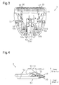
- the head 3 will now be described with reference to Figs. 2 and 3 .
- the head 3 includes clipper blades 4, a fixed frame 50, a holding frame 51, and a pushing device 54.
- the clipper blades 4 include a fixed blade 30 and a movable blade 40.
- the fixed blade 30 and the movable blade 40 are held one above the other. Further, the movable blade 40 is able to oscillate in a sideward direction (described later) relative to the fixed blade 30.
- the fixed frame 50 supports the fixed blade 30 from the lower side (side opposite to the side of the fixed blade 30 where the movable blade 40 is arranged).
- the fixed frame 50 holds the fixed blade 30 so that the fixed blade 30 is not displaced relative to the fixed frame 50.
- the holding frame 51 holds the movable blade 40 from the upper side (side of the movable blade 40 opposite to the side the fixed blade 30 is arranged).
- the holding frame 51 holds the movable blade 40 so that the movable blade 40 is not displaced relative to the holding frame 51.
- the holding frame 51 includes a plate 52 forced against the movable blade 40.
- An engagement unit 53 engaged with the output shaft 21a of the drive mechanism 21 is arranged on the plate 52.
- the engagement unit 53 includes a fitting portion 53a.
- the output shaft 21a is fitted to the fitting portion 53a.
- the pushing device 54 pushes the movable blade 40 and the plate 52 so that the fixed blade 30 and the movable blade 40 are pressed against each other.
- the pushing device 54 includes, for example, two coupled torsion springs 54a and 54b (refer to Fig. 3 ).
- the pushing device 54 is coupled to the fixed frame 50 so that an end 54c of the torsion spring 54a and an end 54d of the torsion spring 54b push the plate 52 and the movable blade 40 toward the fixed blade 30.
- the direction extending from the fixed blade 30 toward the movable blade 40 is referred to as “the upper direction” and a certain subject is located at “the upper side” when arranged in the upper direction from a predetermined object.
- the direction opposite to the upper direction is referred to as “the lower direction” and a certain subject is located at “the lower side” when arranged in the lower direction from a predetermined object.
- the fixed blade 30 is located at the upper side of the fixed frame 50.
- the movable blade 40 is located at the upper side of the fixed blade 30.
- the movable blade 40 is held by the holding frame 51.
- the plate 52 of the holding frame 51 is located at the upper side of the movable blade 40.
- the torsion spring ends 54c and 54d are located at the upper side of the plate 52 and push the plate 52 in the lower direction. Such a structure presses the movable blade 40 against the fixed blade 30.
- the fixed blade 30 includes a plate-like main body 31 (refer to Fig. 2 ) and a plurality of blade bodies 32 extending from the main body 31.
- the blade bodies 32 are laid out along a straight line at substantially constant intervals.
- the direction in which the blade bodies 32 are laid out is referred to as "the sideward direction.”
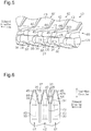
- Each blade body 32 includes a base 33 (refer to Fig. 6 ) extending from the main body 31, a cutting portion 34 further extending from the base 33, and a blade body distal portion 35 further extending from the cutting portion 34.
- the cutting portion 34 includes a fixed slide-contact surface 34a (refer to Fig. 7 ) that slides in contact with the movable blade 40. As shown in Fig. 6 , the cutting portion 34 includes a section tapered toward the blade body distal portion 35 in a plan view. More specifically, the cutting portion 34 has a width (length in sideward direction) that gradually decreases toward the blade body distal portion 35.
- the movable blade 40 includes a plate-like main body 41 (refer to Fig. 2 ) and a plurality of blade bodies 42 extending from the main body 41.
- the blade bodies 42 are laid out along a straight line in substantially constant intervals.
- the blade bodies 42 are laid out in a direction that is the same as the layout direction (sideward direction) of the fixed blade 30.
- Each blade body 42 includes a base 43 (refer to Fig. 6 ) extending from the main body 41, a cutting portion 44 further extending from the base 43, a blade body distal portion 45 further extending from the cutting portion 44, and a cutting blade 48 (refer to Fig. 9 ).
- the cutting blade 48 is arranged on each side surface 42b of the blade body 42 from the cutting portion 44 to the blade body distal portion 45. Figs. 5 and 6 do not show the cutting blade 48.
- the base 43 is inclined relative to the main body 41 (refer to Fig. 5 ).
- the cutting portion 44 includes a plane that is substantially parallel to the main body 41.
- the cutting portion 44 includes a movable slide-contact surface 44a (refer to Fig. 7 ) that slides in contact with the fixed blade 30.
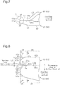
- the movable slide-contact surface 44a is shorter in the front-rear direction than the fixed slide-contact surface 34a of the cutting portion 34 of the fixed blade 30 (refer to Fig. 7 ).
- the cutting portion 44 includes a section tapered toward the blade body distal portion 45 in a plan view. More specifically, the cutting portion 44 has a width (length in sideward direction) that gradually decreases toward the blade body distal portion 45.
- the interval (pitch) of the blade bodies 42 of the movable blade 40 differs from the interval (pitch) of the blade bodies 32 of the fixed blade 30 due to the following reason.
- the interval of the blade bodies 32 of the fixed blade 30 were to be the same as the interval of the blade bodies 42 of the movable blade 40, the sets of blade bodies (blade body 32 of fixed blade 30 and corresponding blade body 42 of movable blade 40) that slide in contact with each other would cut hair at the same timing.
- the power of the motor would have to be increased.
- the size requirements of the main body device 2 limit increases in the motor power. Due to such circumstances, the interval (pitch) of the blade bodies 32 of the fixed blade 30 differs from the interval (pitch) of the blade bodies 42 of the movable blade 40 so that a large amount of hair is not cut at the same time.
- the cutting portions 34 of the blade bodies 32 of the fixed blade 30 slide in contact with the cutting portions 44 of the blade bodies 42 of the movable blade 40.
- the most distal point 32a of each blade body 32 of the fixed blade 30 substantially conforms, in the front-rear direction of the blade bodies 32 and 42, to the most distal point 42a of each blade body 42.
- the distance in the front-rear direction between the most distal point 32a of the blade body 32 of the fixed blade 30 and the most distal point 42a of the blade body 42 of the movable blade 40 is referred to as "the level difference.”
- the level difference is set to substantially "0.”
- Fig. 8 is an enlarged view showing portion A of Fig. 7 .
- the blade body distal portion 35 of the blade body 32 of the fixed blade 30 includes an inner surface 36 facing the movable blade 40, an outer surface 37 continuous with the inner surface 36 and facing the outer side, and a side surface 32s facing the adjacent blade body 32.
- the outer surface 37 is curved.
- the inner surface 36 is continuous with the fixed slide-contact surface 34a and extends to the distal end.
- the inner surface 36 includes a flat surface inclined relative to the fixed slide-contact surface 34a.
- a plane (hypothetical plane) including the fixed slide-contact surface 34a is set as a reference plane SK1
- the inner surface 36 is located at the side of the reference plane SK1 where the fixed blade 30 is arranged.
- the blade body distal portion 45 of the blade body 42 of the movable blade 40 includes an inner surface 46 facing the movable blade 40, an outer surface 47 continuous with the inner surface 46 and facing the outer side, and a side surface 42s facing the adjacent blade body 42.
- the outer surface 47 is curved.
- the inner surface 46 is continuous with the movable slide-contact surface 44a and extends to the distal end.
- the inner surface 46 includes a flat surface inclined relative to the movable slide-contact surface 44a.
- a plane (hypothetical plane) including the movable slide-contact surface 44a is set as a reference plane SK2
- the inner surface 46 is located at the side of the reference plane SK2 where the movable blade 40 is arranged.
- the two inner surfaces 36 and 46 form a gap Sn between the blade body distal portion 35 of the blade body 32 of the fixed blade 30 and the blade body distal portion 45 of the blade body 42 of the movable blade 40. Due to the gap Sn, the fixed slide-contact surface 34a and the movable slide-contact surface 44a are located inwardly (toward bases 33 and 43) from the distal ends of the clipper blades 4.
- the blade body distal portion 45 of the blade body 42 of the movable blade 40 has the following structure.
- the movable slide-contact surface 44a of the blade body 42 of the movable blade 40 is located inwardly (toward base 33) from the fixed slide-contact surface 34a of the blade body 32 of the fixed blade 30. That is, a distal edge 44b of the movable slide-contact surface 44a is located inwardly (toward base 43) from a distal edge 34b of the fixed slide-contact surface 34a in the front-rear direction. Due to such a structure, a gap Sx, which is narrower than the gap Sn between the two inner surfaces 36 and 46, is formed between the inner surface 46 of the blade body 42 of the movable blade 40 and the fixed slide-contact surface 34a of the blade body 32 of the fixed blade 30.
- the structure of the blade body distal portion 45 of the blade body 42 of the movable blade 40 has the following structure.
- a distal point 47b which is the most frontward point in the front-rear direction on a borderline 47a (refer to Fig. 5 ) between the inner surface 46 and the outer surface 47 of the blade body distal portion 45, is located between an upper surface 47c of the blade body distal portion 45 and the movable slide-contact surface 44a.
- the distance L2 between the distal point 47b and the upper surface 47c is set to be greater than the distance L1 between the distal point 47b and the movable slide-contact surface 44a.
- the outer surface 47 of the blade body distal portion 45 has a thickness (length in vertical direction) (distance L2) that is greater than at least one half of the thickness of the blade body distal portion 45.
- the upper surface 47c of the blade body distal portion 45 includes the vertically uppermost point in a line of intersection of the outer surface 47 and a hypothetical plane orthogonal to the movable slide-contact surface 44a extending from a distal edge 44b of the movable slide-contact surface 44a. Further, the upper surface 47c of the blade body distal portion 45 is a surface (double-dashed line in Fig. 8 ) that is parallel to the movable slide-contact surface 44a.
- Fig. 9 is a cross-sectional view taken along line B-B in Fig. 8 .
- Fig. 10 is a cross-sectional view taken along line C-C in Fig. 8 .
- the blade body 42 of the movable blade 40 includes the cutting blade 48 at each of the two side surfaces 42b.
- the blade body 42 of the movable blade 40 includes the cutting blades 48 that project from the two side surfaces 42b toward the adjacent side surface (in the sideward direction).
- a first section in the cutting portion 44 of each cutting blade 48 includes a blade edge 48b having an acute shape. More specifically, as shown in Fig. 9 , the lower surface of the cutting blade 48 corresponds to an extended plane of the movable slide-contact surface 44a, and the angle of the blade edge 48b of the cutting blade 48 is 90 degrees or less.
- a second section in the blade body distal portion 45 of each cutting blade 48 includes a blade edge 48a having an obtuse shape.
- the blade edge 48a of the cutting blade 48 has a curved surface.
- the inner surface 46 of the blade body distal portion 45 in the movable blade 40 is not in contact with the blade body distal portion 35 of the fixed blade 30. Accordingly, the clipper blades 4 are not designed to cut hair by sliding the blade body distal portion 45 of the movable blade 40 on the blade body distal portion 35 of the fixed blade 30. If the cutting blade 48, which is arranged on each side surface 42s of the blade body distal portion 45, were to have an acute shape, the skin S may be damaged when this portion contacts the skin S during oscillation of the movable blade 40. Thus, the blade edge 48a of the cutting blade 48 at this portion has a curved surface.
- Fig. 11 shows deformation of the skin S when the head 3 is pressed against the skin S.
- Fig. 11A shows deformation of the skin S when the blade bodies 32 of the fixed blade 30 are overlapped with the blade bodies 42 of the movable blade 40 in the sideward direction.
- the skin S enters the space between the adjacent blade bodies 32 of the fixed blade 30 and the adjacent blade bodies 42 of the movable blade 40.
- Fig. 11B shows deformation of the skin S when the blade bodies 32 of the fixed blade 30 are not overlapped with the blade bodies 42 of the movable blade 40. More specifically, Fig. 11B shows deformation of the skin S when the blade bodies 42 of the movable blade 40 are arranged between the adjacent blade bodies 32 of the fixed blade 30. In this situation, the movement of the movable blade 40 pushes back the skin S from between the blade bodies 32 of the fixed blade 30 and the blade bodies 42 of the movable blade 40. More specifically, as shown in Figs. 11A and 11B , due to the oscillation of the movable blade 40, the skin S is moved into or pushed out of the space between the blade bodies 32 of the fixed blade 30 and the space between the blade bodies 42 of the movable blade 40.
- Figs. 12 and 13 are diagrams of views taken from the distal end of the blade bodies 32, 42, 132, and 142 toward the base when the blades 4 and 100 of the clipper pressed against the skin S cuts the skin S along a plane of the one of the blade bodies 32, 42, 132, and 142 that that contacts the skin S.
- Fig. 12 is a diagram of clipper blades 100 having a prior art structure showing deformation of the skin S when the skin S enters the space between a blade body 142 of a movable blade 140 and a blade body 132 of a fixed blade 130.
- the gap Sn does not exist between a blade body distal portion 135 of the blade body 132 of the fixed blade 130 and a blade body distal portion 145 of the blade body 142 of the movable blade 140.
- Fig. 13 is a diagram of the clipper blades 4 in the present embodiment showing deformation of the skin S when the skin S enters the space between the blade body 42 of the movable blade 40 and the blade body 32 of the fixed blade 30.
- the fixed slide-contact surface 34a of the blade body distal portion 35 and the movable slide-contact surface 44a of the blade body distal portion 45 exist at the inner side of the pressing surfaces (outer surfaces 37 and 47) that push the skin at the blade body distal portion 35 and the blade body distal portion 45. This limits entrapment of the skin S.
- the clipper blades 4 of the present embodiment also function in the following manner.
- the outer surface 47 of the blade body distal portion 45 of the blade body 42 of the movable blade 40 is a curved surface having a distance (thickness) set to increase the area of contact with the skin S. Compared to a flat surface, a curved surface reduces the entrapment of the skin S. Further, the large area of contact with the skin S disperses the force of the blade body distal portion 45 of the blade body 42 of the movable blade 40 that acts to press the skin S. Thus, the clipper blades 4 limit damage to the skin S in comparison with a blade body distal portion having an acute shape or a distance L2 that is less than the distance L1.
- the gaps Sn and Sx are formed between the inner surface 46 of the blade body distal portion 45 of the movable blade 40 and the fixed slide-contact surface 34a of the fixed blade 30 to reduce the skin S caught between the blade bodies 32 and 42 that move toward each other. This limits damage to the skin S.
- the blade body distal portion 45 of the movable blade 40 and the blade body distal portion 35 of the fixed blade 30 are formed by undergoing machining or the like. This facilitates manufacturing compared to the prior art that uses a resin to form a curved surface at the distal end of the blade body distal portion 45 of the movable blade 40.
- the clipper blades 4 have superior manufacturing characteristics compared to the prior art.
- the clipper 1 having such a structure includes the clipper blades 4 of the above-described structure. Thus, when cutting hair, damage to the skin S is limited.
- the clipper 1 may include embodiments other than the above embodiment. Other embodiments will now be described as modified examples of the above embodiment. The modified examples described below may be combined.
- the inner surface 36 in the blade body distal portion 35 of the fixed blade 30 is located at the side of the reference plane where the fixed blade 30 is arranged.
- the inner surface 36 may have the following structure.
- the inner surface 36 may be omitted from the blade body distal portion 35 of the fixed blade 30, and the fixed slide-contact surface 34a may be extended toward the blade body distal portion 35.
- This case also includes the gap Sn between the blade body distal portion 35 of the fixed blade 30 and the blade body distal portion 45 of the movable blade 40.
- the inner surface 46 of the blade body distal portion 45 of the movable blade 40 has a flat surface.
- the inner surface 46 is not limited to such a form.
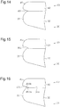
- Fig. 14 shows another form of the inner surface 46 of the blade body distal portion 45 of the movable blade 40.
- an inner surface 461 has a concave shape. This structure enlarges the gap Sn between the blade body distal portion 45 of the movable blade 40 and the fixed slide-contact surface 34a of the fixed blade 30 and limits entrapment of the skin S.
- Fig. 15 shows a further form of the inner surface 46 of the blade body distal portion 45 of the movable blade 40.
- an inner surface 462 has a curved shape in which the middle portion of the surface is bulged upward. This structure functions to push back the skin S.
- Such a structure has an advantage similar to advantage (1).
- Fig. 16 shows a further form of the inner surface 46 of the blade body distal portion 45 of the movable blade 40.
- the inner surface 463 is formed by two surfaces (first surface 463a and second surface 463b).
- the inner surface 463 includes the first surface 463a, which is generally orthogonal to the fixed slide-contact surface 34a of the fixed blade 30, and the second surface 463b, which is a sloped surface extending from the first surface 463a toward the distal side.
- Such a structure has an advantage similar to advantage (1).
- the inner surface 46 of the blade body distal portion 45 of the movable blade 40 is flat, and the outer surface 47 is curved.
- the blade body distal portion 45 of the movable blade 40 is not limited to such a form.
- Fig. 17 shows a further form of the blade body distal portion 45 of the movable blade 40.
- a border portion 470 including a curved surface is located between the inner surface 46 and the outer surface 47.
- corners are omitted from the blade body distal portion 45. This limits damage (abrasion) of the skin S caused by the movable blade 40.
- This structure eliminates the borderline 47a between the inner surface 46 and the outer surface 47.
- the most distal point 42a of the blade body 42 is used to define the distances L1 and L2.
- part of the blade body distal portion 45 in the cutting blade 48 includes the blade edge 48a that has a curved surface.
- the blade edge 48a is not limited to such a shape.
- Fig. 18 shows a different form of the blade edge 48a at the blade body distal portion of the cutting blade 48.
- the blade edge 480a includes a chamfered portion. Such a structure also limits damage to the skin S.
- the distance between the most distal point 32a of the blade body 32 of the fixed blade 30 and the most distal point 42a of the blade body 42 of the movable blade 40 is set to substantially “0.”
- the level difference is not limited to substantially “0.”
- the allowed level difference is in the range of approximately 0 to 0.5 mm.
Landscapes
- Life Sciences & Earth Sciences (AREA)
- Forests & Forestry (AREA)
- Engineering & Computer Science (AREA)
- Mechanical Engineering (AREA)
- Dry Shavers And Clippers (AREA)
Claims (3)
- Schneiderklingen (4) umfassend:eine feste Klinge (30) umfassend eine Vielzahl von Klingenkörpern (32); undeine bewegliche Klinge (40) umfassend eine Vielzahl von Klingenkörpern (42), angeordnet in einer Richtung, welche die gleiche ist wie eine Richtung, in der die Klingenkörper (32) der festen Klinge (30) angeordnet sind, wobeidie Klingenkörper (42) der beweglichen Klinge (40) jeweils einen Schneidabschnitt (44) umfassen, der eine bewegliche Gleitkontaktfläche (44a), welche die feste Klinge (30) berührt, und einen Klingenkörper-Distalabschnitt (45), der an einer distalen Seite des Schneidabschnitts 44) angeordnet ist, umfasst undder Klingenkörper-Distalabschnitt (45) der beweglichen Klinge (40) eine an einer Seite, an der die bewegliche Klinge (40) auf einer Ebene umfassend die bewegliche Gleitkontaktfläche (44a) angeordnet ist, angeordnete Innenfläche (46) umfasst,jeder der Klingenkörper (42) der beweglichen Klinge (40) eine auf jeder von zwei Seitenflächen des Klingenkörpers (42) angeordnete Schneidklinge (48) umfasst, unddadurch gekennzeichnet, dassein Teil der im Klingenkörper-Distalabschnitt (45) angeordneten Schneidklinge (48) eine schräge Klingenschneide (48a) in der seitlichen Richtung umfasst.
- Schneiderklingen nach Anspruch 1, wobei
der Klingenkörper-Distalabschnitt (45) der beweglichen Klinge (40) die Innenfläche (46) und eine Außenfläche (47), die durchlaufend mit der Innenfläche (46) ist und zu einer Außenseite zeigt, umfasst,
ein distaler Punkt (47b) auf einer Randlinie (47a) zwischen der Innenfläche (46) und der Außenfläche (47) des Klingenkörper-Distalabschnitts (45) der beweglichen Klinge (40) zwischen einer oberen Fläche (47c) des Klingenkörper-Distalabschnitts (45) und der beweglichen Gleitkontaktfläche (44a) vorhanden ist, und
ein Abstand (L2) zwischen dem distalen Punkt (47b) und der oberen Fläche (47c) größer ist als ein Abstand (L1) zwischen dem distalen Punkt (47b) und der beweglichen Gleitkontaktfläche (44a). - Schneider (1) umfassend die Schneiderklingen (4) nach Anspruch 1 oder 2.
Applications Claiming Priority (2)
| Application Number | Priority Date | Filing Date | Title |
|---|---|---|---|
| JP2012281669A JP6016023B2 (ja) | 2012-12-25 | 2012-12-25 | バリカンの刃、及びバリカンの刃を備えたバリカン |
| PCT/JP2013/006908 WO2014103162A1 (ja) | 2012-12-25 | 2013-11-25 | バリカンの刃、及びバリカンの刃を備えたバリカン |
Publications (3)
| Publication Number | Publication Date |
|---|---|
| EP2939802A1 EP2939802A1 (de) | 2015-11-04 |
| EP2939802A4 EP2939802A4 (de) | 2016-01-20 |
| EP2939802B1 true EP2939802B1 (de) | 2019-07-03 |
Family
ID=51020291
Family Applications (1)
| Application Number | Title | Priority Date | Filing Date |
|---|---|---|---|
| EP13866943.7A Active EP2939802B1 (de) | 2012-12-25 | 2013-11-25 | Klinge einer haarschneidevorrichtung und haarschneidevorrichtung mit dieser klinge |
Country Status (3)
| Country | Link |
|---|---|
| EP (1) | EP2939802B1 (de) |
| JP (1) | JP6016023B2 (de) |
| WO (1) | WO2014103162A1 (de) |
Cited By (3)
| Publication number | Priority date | Publication date | Assignee | Title |
|---|---|---|---|---|
| US12370705B2 (en) | 2021-09-14 | 2025-07-29 | Wahl Clipper Corporation | Hair clipper bladeset with variable rake angle array tooth geometry |
| USD1099427S1 (en) | 2021-09-14 | 2025-10-21 | Wahl Clipper Corporation | Hair clipper bladeset |
| EP4699751A1 (de) | 2024-08-21 | 2026-02-25 | Braun GmbH | Elektrischer haarschneider zum schneiden von intimhaar |
Families Citing this family (7)
| Publication number | Priority date | Publication date | Assignee | Title |
|---|---|---|---|---|
| JP6341379B2 (ja) | 2014-09-30 | 2018-06-13 | パナソニックIpマネジメント株式会社 | トリマーの刃およびこれを備えるトリマー |
| EP3566828A1 (de) * | 2018-05-08 | 2019-11-13 | Koninklijke Philips N.V. | Stationäre klinge, klingensatz und haarschneidegerät |
| CN110181562A (zh) * | 2019-06-26 | 2019-08-30 | 温州市日电电器有限公司 | 一种剃须刀刀头弹片结构 |
| JP7349682B2 (ja) * | 2020-02-14 | 2023-09-25 | パナソニックIpマネジメント株式会社 | 除毛装置の刃および除毛装置の刃を備える除毛装置 |
| USD1013267S1 (en) * | 2021-09-22 | 2024-01-30 | Manscaped, Llc | Blade and guard |
| JP7825172B2 (ja) * | 2021-12-06 | 2026-03-06 | パナソニックIpマネジメント株式会社 | バリカンの刃およびバリカン |
| EP4699750A1 (de) | 2024-08-21 | 2026-02-25 | Braun GmbH | Elektrischer haarschneider |
Family Cites Families (7)
| Publication number | Priority date | Publication date | Assignee | Title |
|---|---|---|---|---|
| JPS577423Y2 (de) * | 1976-08-02 | 1982-02-12 | ||
| JPS548052A (en) * | 1977-06-20 | 1979-01-22 | Matsushita Electric Works Ltd | Blade of electric razor |
| JPS55101286A (en) | 1979-12-28 | 1980-08-01 | Hamasawa Kogyo Kk | Edge shaving edge of electric razor |
| JPS5985166U (ja) * | 1983-08-08 | 1984-06-08 | 日立マクセル株式会社 | 電気かみそりのくし刃 |
| GB8703367D0 (en) * | 1987-02-13 | 1987-03-18 | Lister Shearing Equip Ltd | Clipper blade assembly |
| JPH0241353A (ja) | 1988-08-01 | 1990-02-09 | Mitsui Toatsu Chem Inc | 半導体封止用樹脂組成物 |
| JPH02305590A (ja) * | 1989-05-22 | 1990-12-19 | Tottori Matsuo | 襟刈バリカン |
-
2012
- 2012-12-25 JP JP2012281669A patent/JP6016023B2/ja active Active
-
2013
- 2013-11-25 EP EP13866943.7A patent/EP2939802B1/de active Active
- 2013-11-25 WO PCT/JP2013/006908 patent/WO2014103162A1/ja not_active Ceased
Non-Patent Citations (1)
| Title |
|---|
| None * |
Cited By (3)
| Publication number | Priority date | Publication date | Assignee | Title |
|---|---|---|---|---|
| US12370705B2 (en) | 2021-09-14 | 2025-07-29 | Wahl Clipper Corporation | Hair clipper bladeset with variable rake angle array tooth geometry |
| USD1099427S1 (en) | 2021-09-14 | 2025-10-21 | Wahl Clipper Corporation | Hair clipper bladeset |
| EP4699751A1 (de) | 2024-08-21 | 2026-02-25 | Braun GmbH | Elektrischer haarschneider zum schneiden von intimhaar |
Also Published As
| Publication number | Publication date |
|---|---|
| WO2014103162A1 (ja) | 2014-07-03 |
| EP2939802A1 (de) | 2015-11-04 |
| JP6016023B2 (ja) | 2016-10-26 |
| EP2939802A4 (de) | 2016-01-20 |
| JP2014124261A (ja) | 2014-07-07 |
Similar Documents
| Publication | Publication Date | Title |
|---|---|---|
| EP2939802B1 (de) | Klinge einer haarschneidevorrichtung und haarschneidevorrichtung mit dieser klinge | |
| EP3691844B1 (de) | Haarschneidemaschine mit einem kamm | |
| US20130104718A1 (en) | Cutter for sheet-like member | |
| CN111902249B (zh) | 修剪刀片以及体毛切断装置 | |
| US10780598B2 (en) | Razor cartridge and razor using same | |
| CN101495276A (zh) | 具有适形的刀片支撑体的湿式剃刀 | |
| US10543608B2 (en) | Electric shaver and outer blade used in the electric shaver | |
| US20070199422A1 (en) | Sheet cutting device, printer, and sheet cutting method | |
| US10632635B2 (en) | Razor | |
| EP4067017B1 (de) | Elektrischer rasierapparat | |
| JP6341379B2 (ja) | トリマーの刃およびこれを備えるトリマー | |
| US20220314474A1 (en) | Blade unit and electric razor | |
| WO2008044538A1 (en) | Outer blade for reciprocation-type electric shaver and method of producing the same | |
| JP2011200492A (ja) | 電気かみそり | |
| US9248578B2 (en) | Electric Shaver | |
| US8925205B2 (en) | Electric shaver | |
| JP4766536B2 (ja) | せん断刃 | |
| JP4479988B2 (ja) | 電気かみそり | |
| CN213859373U (zh) | 一种定刀在外、动刀在内的剃须刀头 | |
| CN115139347B (zh) | 刀片单元和电动剃刀 | |
| CN115139347A (zh) | 刀片单元和电动剃刀 | |
| EP2554339B1 (de) | Elektrischer rasierapparat | |
| CN115644583A (zh) | 电动指甲剪 | |
| KR20170056392A (ko) | 손톱 길이 조절구가 구비된 손톱깎이 | |
| JP2721478B2 (ja) | 切断具 |
Legal Events
| Date | Code | Title | Description |
|---|---|---|---|
| PUAI | Public reference made under article 153(3) epc to a published international application that has entered the european phase |
Free format text: ORIGINAL CODE: 0009012 |
|
| 17P | Request for examination filed |
Effective date: 20150617 |
|
| AK | Designated contracting states |
Kind code of ref document: A1 Designated state(s): AL AT BE BG CH CY CZ DE DK EE ES FI FR GB GR HR HU IE IS IT LI LT LU LV MC MK MT NL NO PL PT RO RS SE SI SK SM TR |
|
| AX | Request for extension of the european patent |
Extension state: BA ME |
|
| A4 | Supplementary search report drawn up and despatched |
Effective date: 20151218 |
|
| RIC1 | Information provided on ipc code assigned before grant |
Ipc: B26B 19/06 20060101AFI20151214BHEP |
|
| DAX | Request for extension of the european patent (deleted) | ||
| STAA | Information on the status of an ep patent application or granted ep patent |
Free format text: STATUS: EXAMINATION IS IN PROGRESS |
|
| 17Q | First examination report despatched |
Effective date: 20180518 |
|
| GRAP | Despatch of communication of intention to grant a patent |
Free format text: ORIGINAL CODE: EPIDOSNIGR1 |
|
| STAA | Information on the status of an ep patent application or granted ep patent |
Free format text: STATUS: GRANT OF PATENT IS INTENDED |
|
| INTG | Intention to grant announced |
Effective date: 20190206 |
|
| GRAS | Grant fee paid |
Free format text: ORIGINAL CODE: EPIDOSNIGR3 |
|
| GRAA | (expected) grant |
Free format text: ORIGINAL CODE: 0009210 |
|
| STAA | Information on the status of an ep patent application or granted ep patent |
Free format text: STATUS: THE PATENT HAS BEEN GRANTED |
|
| AK | Designated contracting states |
Kind code of ref document: B1 Designated state(s): AL AT BE BG CH CY CZ DE DK EE ES FI FR GB GR HR HU IE IS IT LI LT LU LV MC MK MT NL NO PL PT RO RS SE SI SK SM TR |
|
| REG | Reference to a national code |
Ref country code: GB Ref legal event code: FG4D |
|
| REG | Reference to a national code |
Ref country code: CH Ref legal event code: EP Ref country code: AT Ref legal event code: REF Ref document number: 1150420 Country of ref document: AT Kind code of ref document: T Effective date: 20190715 |
|
| REG | Reference to a national code |
Ref country code: IE Ref legal event code: FG4D |
|
| REG | Reference to a national code |
Ref country code: DE Ref legal event code: R096 Ref document number: 602013057511 Country of ref document: DE |
|
| REG | Reference to a national code |
Ref country code: NL Ref legal event code: MP Effective date: 20190703 |
|
| REG | Reference to a national code |
Ref country code: LT Ref legal event code: MG4D |
|
| REG | Reference to a national code |
Ref country code: AT Ref legal event code: MK05 Ref document number: 1150420 Country of ref document: AT Kind code of ref document: T Effective date: 20190703 |
|
| PG25 | Lapsed in a contracting state [announced via postgrant information from national office to epo] |
Ref country code: CZ Free format text: LAPSE BECAUSE OF FAILURE TO SUBMIT A TRANSLATION OF THE DESCRIPTION OR TO PAY THE FEE WITHIN THE PRESCRIBED TIME-LIMIT Effective date: 20190703 Ref country code: FI Free format text: LAPSE BECAUSE OF FAILURE TO SUBMIT A TRANSLATION OF THE DESCRIPTION OR TO PAY THE FEE WITHIN THE PRESCRIBED TIME-LIMIT Effective date: 20190703 Ref country code: NO Free format text: LAPSE BECAUSE OF FAILURE TO SUBMIT A TRANSLATION OF THE DESCRIPTION OR TO PAY THE FEE WITHIN THE PRESCRIBED TIME-LIMIT Effective date: 20191003 Ref country code: HR Free format text: LAPSE BECAUSE OF FAILURE TO SUBMIT A TRANSLATION OF THE DESCRIPTION OR TO PAY THE FEE WITHIN THE PRESCRIBED TIME-LIMIT Effective date: 20190703 Ref country code: LT Free format text: LAPSE BECAUSE OF FAILURE TO SUBMIT A TRANSLATION OF THE DESCRIPTION OR TO PAY THE FEE WITHIN THE PRESCRIBED TIME-LIMIT Effective date: 20190703 Ref country code: PT Free format text: LAPSE BECAUSE OF FAILURE TO SUBMIT A TRANSLATION OF THE DESCRIPTION OR TO PAY THE FEE WITHIN THE PRESCRIBED TIME-LIMIT Effective date: 20191104 Ref country code: NL Free format text: LAPSE BECAUSE OF FAILURE TO SUBMIT A TRANSLATION OF THE DESCRIPTION OR TO PAY THE FEE WITHIN THE PRESCRIBED TIME-LIMIT Effective date: 20190703 Ref country code: AT Free format text: LAPSE BECAUSE OF FAILURE TO SUBMIT A TRANSLATION OF THE DESCRIPTION OR TO PAY THE FEE WITHIN THE PRESCRIBED TIME-LIMIT Effective date: 20190703 Ref country code: SE Free format text: LAPSE BECAUSE OF FAILURE TO SUBMIT A TRANSLATION OF THE DESCRIPTION OR TO PAY THE FEE WITHIN THE PRESCRIBED TIME-LIMIT Effective date: 20190703 Ref country code: BG Free format text: LAPSE BECAUSE OF FAILURE TO SUBMIT A TRANSLATION OF THE DESCRIPTION OR TO PAY THE FEE WITHIN THE PRESCRIBED TIME-LIMIT Effective date: 20191003 |
|
| PG25 | Lapsed in a contracting state [announced via postgrant information from national office to epo] |
Ref country code: GR Free format text: LAPSE BECAUSE OF FAILURE TO SUBMIT A TRANSLATION OF THE DESCRIPTION OR TO PAY THE FEE WITHIN THE PRESCRIBED TIME-LIMIT Effective date: 20191004 Ref country code: LV Free format text: LAPSE BECAUSE OF FAILURE TO SUBMIT A TRANSLATION OF THE DESCRIPTION OR TO PAY THE FEE WITHIN THE PRESCRIBED TIME-LIMIT Effective date: 20190703 Ref country code: AL Free format text: LAPSE BECAUSE OF FAILURE TO SUBMIT A TRANSLATION OF THE DESCRIPTION OR TO PAY THE FEE WITHIN THE PRESCRIBED TIME-LIMIT Effective date: 20190703 Ref country code: IS Free format text: LAPSE BECAUSE OF FAILURE TO SUBMIT A TRANSLATION OF THE DESCRIPTION OR TO PAY THE FEE WITHIN THE PRESCRIBED TIME-LIMIT Effective date: 20191103 Ref country code: RS Free format text: LAPSE BECAUSE OF FAILURE TO SUBMIT A TRANSLATION OF THE DESCRIPTION OR TO PAY THE FEE WITHIN THE PRESCRIBED TIME-LIMIT Effective date: 20190703 Ref country code: ES Free format text: LAPSE BECAUSE OF FAILURE TO SUBMIT A TRANSLATION OF THE DESCRIPTION OR TO PAY THE FEE WITHIN THE PRESCRIBED TIME-LIMIT Effective date: 20190703 |
|
| PG25 | Lapsed in a contracting state [announced via postgrant information from national office to epo] |
Ref country code: TR Free format text: LAPSE BECAUSE OF FAILURE TO SUBMIT A TRANSLATION OF THE DESCRIPTION OR TO PAY THE FEE WITHIN THE PRESCRIBED TIME-LIMIT Effective date: 20190703 |
|
| PG25 | Lapsed in a contracting state [announced via postgrant information from national office to epo] |
Ref country code: RO Free format text: LAPSE BECAUSE OF FAILURE TO SUBMIT A TRANSLATION OF THE DESCRIPTION OR TO PAY THE FEE WITHIN THE PRESCRIBED TIME-LIMIT Effective date: 20190703 Ref country code: IT Free format text: LAPSE BECAUSE OF FAILURE TO SUBMIT A TRANSLATION OF THE DESCRIPTION OR TO PAY THE FEE WITHIN THE PRESCRIBED TIME-LIMIT Effective date: 20190703 Ref country code: PL Free format text: LAPSE BECAUSE OF FAILURE TO SUBMIT A TRANSLATION OF THE DESCRIPTION OR TO PAY THE FEE WITHIN THE PRESCRIBED TIME-LIMIT Effective date: 20190703 Ref country code: DK Free format text: LAPSE BECAUSE OF FAILURE TO SUBMIT A TRANSLATION OF THE DESCRIPTION OR TO PAY THE FEE WITHIN THE PRESCRIBED TIME-LIMIT Effective date: 20190703 Ref country code: EE Free format text: LAPSE BECAUSE OF FAILURE TO SUBMIT A TRANSLATION OF THE DESCRIPTION OR TO PAY THE FEE WITHIN THE PRESCRIBED TIME-LIMIT Effective date: 20190703 |
|
| PG25 | Lapsed in a contracting state [announced via postgrant information from national office to epo] |
Ref country code: IS Free format text: LAPSE BECAUSE OF FAILURE TO SUBMIT A TRANSLATION OF THE DESCRIPTION OR TO PAY THE FEE WITHIN THE PRESCRIBED TIME-LIMIT Effective date: 20200224 Ref country code: SM Free format text: LAPSE BECAUSE OF FAILURE TO SUBMIT A TRANSLATION OF THE DESCRIPTION OR TO PAY THE FEE WITHIN THE PRESCRIBED TIME-LIMIT Effective date: 20190703 Ref country code: SK Free format text: LAPSE BECAUSE OF FAILURE TO SUBMIT A TRANSLATION OF THE DESCRIPTION OR TO PAY THE FEE WITHIN THE PRESCRIBED TIME-LIMIT Effective date: 20190703 |
|
| REG | Reference to a national code |
Ref country code: DE Ref legal event code: R097 Ref document number: 602013057511 Country of ref document: DE |
|
| REG | Reference to a national code |
Ref country code: CH Ref legal event code: PL |
|
| PLBE | No opposition filed within time limit |
Free format text: ORIGINAL CODE: 0009261 |
|
| STAA | Information on the status of an ep patent application or granted ep patent |
Free format text: STATUS: NO OPPOSITION FILED WITHIN TIME LIMIT |
|
| PG2D | Information on lapse in contracting state deleted |
Ref country code: IS |
|
| PG25 | Lapsed in a contracting state [announced via postgrant information from national office to epo] |
Ref country code: CH Free format text: LAPSE BECAUSE OF NON-PAYMENT OF DUE FEES Effective date: 20191130 Ref country code: LI Free format text: LAPSE BECAUSE OF NON-PAYMENT OF DUE FEES Effective date: 20191130 Ref country code: MC Free format text: LAPSE BECAUSE OF FAILURE TO SUBMIT A TRANSLATION OF THE DESCRIPTION OR TO PAY THE FEE WITHIN THE PRESCRIBED TIME-LIMIT Effective date: 20190703 Ref country code: LU Free format text: LAPSE BECAUSE OF NON-PAYMENT OF DUE FEES Effective date: 20191125 |
|
| 26N | No opposition filed |
Effective date: 20200603 |
|
| REG | Reference to a national code |
Ref country code: BE Ref legal event code: MM Effective date: 20191130 |
|
| PG25 | Lapsed in a contracting state [announced via postgrant information from national office to epo] |
Ref country code: SI Free format text: LAPSE BECAUSE OF FAILURE TO SUBMIT A TRANSLATION OF THE DESCRIPTION OR TO PAY THE FEE WITHIN THE PRESCRIBED TIME-LIMIT Effective date: 20190703 |
|
| GBPC | Gb: european patent ceased through non-payment of renewal fee |
Effective date: 20191125 |
|
| PG25 | Lapsed in a contracting state [announced via postgrant information from national office to epo] |
Ref country code: FR Free format text: LAPSE BECAUSE OF NON-PAYMENT OF DUE FEES Effective date: 20191130 Ref country code: GB Free format text: LAPSE BECAUSE OF NON-PAYMENT OF DUE FEES Effective date: 20191125 Ref country code: IE Free format text: LAPSE BECAUSE OF NON-PAYMENT OF DUE FEES Effective date: 20191125 |
|
| PG25 | Lapsed in a contracting state [announced via postgrant information from national office to epo] |
Ref country code: BE Free format text: LAPSE BECAUSE OF NON-PAYMENT OF DUE FEES Effective date: 20191130 |
|
| PG25 | Lapsed in a contracting state [announced via postgrant information from national office to epo] |
Ref country code: CY Free format text: LAPSE BECAUSE OF FAILURE TO SUBMIT A TRANSLATION OF THE DESCRIPTION OR TO PAY THE FEE WITHIN THE PRESCRIBED TIME-LIMIT Effective date: 20190703 |
|
| PG25 | Lapsed in a contracting state [announced via postgrant information from national office to epo] |
Ref country code: MT Free format text: LAPSE BECAUSE OF FAILURE TO SUBMIT A TRANSLATION OF THE DESCRIPTION OR TO PAY THE FEE WITHIN THE PRESCRIBED TIME-LIMIT Effective date: 20190703 Ref country code: HU Free format text: LAPSE BECAUSE OF FAILURE TO SUBMIT A TRANSLATION OF THE DESCRIPTION OR TO PAY THE FEE WITHIN THE PRESCRIBED TIME-LIMIT; INVALID AB INITIO Effective date: 20131125 |
|
| PG25 | Lapsed in a contracting state [announced via postgrant information from national office to epo] |
Ref country code: MK Free format text: LAPSE BECAUSE OF FAILURE TO SUBMIT A TRANSLATION OF THE DESCRIPTION OR TO PAY THE FEE WITHIN THE PRESCRIBED TIME-LIMIT Effective date: 20190703 |
|
| PGFP | Annual fee paid to national office [announced via postgrant information from national office to epo] |
Ref country code: DE Payment date: 20251119 Year of fee payment: 13 |