EP2939084B1 - Information processing apparatus, information processing method, and program - Google Patents
Information processing apparatus, information processing method, and program Download PDFInfo
- Publication number
- EP2939084B1 EP2939084B1 EP13803276.8A EP13803276A EP2939084B1 EP 2939084 B1 EP2939084 B1 EP 2939084B1 EP 13803276 A EP13803276 A EP 13803276A EP 2939084 B1 EP2939084 B1 EP 2939084B1
- Authority
- EP
- European Patent Office
- Prior art keywords
- objects
- user
- image
- information processing
- hand
- Prior art date
- Legal status (The legal status is an assumption and is not a legal conclusion. Google has not performed a legal analysis and makes no representation as to the accuracy of the status listed.)
- Active
Links
Images


Classifications
-
- G—PHYSICS
- G06—COMPUTING OR CALCULATING; COUNTING
- G06F—ELECTRIC DIGITAL DATA PROCESSING
- G06F3/00—Input arrangements for transferring data to be processed into a form capable of being handled by the computer; Output arrangements for transferring data from processing unit to output unit, e.g. interface arrangements
- G06F3/01—Input arrangements or combined input and output arrangements for interaction between user and computer
- G06F3/011—Arrangements for interaction with the human body, e.g. for user immersion in virtual reality
-
- G—PHYSICS
- G06—COMPUTING OR CALCULATING; COUNTING
- G06F—ELECTRIC DIGITAL DATA PROCESSING
- G06F3/00—Input arrangements for transferring data to be processed into a form capable of being handled by the computer; Output arrangements for transferring data from processing unit to output unit, e.g. interface arrangements
- G06F3/01—Input arrangements or combined input and output arrangements for interaction between user and computer
- G06F3/048—Interaction techniques based on graphical user interfaces [GUI]
- G06F3/0484—Interaction techniques based on graphical user interfaces [GUI] for the control of specific functions or operations, e.g. selecting or manipulating an object, an image or a displayed text element, setting a parameter value or selecting a range
- G06F3/0486—Drag-and-drop
-
- G—PHYSICS
- G06—COMPUTING OR CALCULATING; COUNTING
- G06F—ELECTRIC DIGITAL DATA PROCESSING
- G06F3/00—Input arrangements for transferring data to be processed into a form capable of being handled by the computer; Output arrangements for transferring data from processing unit to output unit, e.g. interface arrangements
- G06F3/01—Input arrangements or combined input and output arrangements for interaction between user and computer
- G06F3/017—Gesture based interaction, e.g. based on a set of recognized hand gestures
-
- G—PHYSICS
- G06—COMPUTING OR CALCULATING; COUNTING
- G06F—ELECTRIC DIGITAL DATA PROCESSING
- G06F3/00—Input arrangements for transferring data to be processed into a form capable of being handled by the computer; Output arrangements for transferring data from processing unit to output unit, e.g. interface arrangements
- G06F3/01—Input arrangements or combined input and output arrangements for interaction between user and computer
- G06F3/048—Interaction techniques based on graphical user interfaces [GUI]
- G06F3/0481—Interaction techniques based on graphical user interfaces [GUI] based on specific properties of the displayed interaction object or a metaphor-based environment, e.g. interaction with desktop elements like windows or icons, or assisted by a cursor's changing behaviour or appearance
- G06F3/04817—Interaction techniques based on graphical user interfaces [GUI] based on specific properties of the displayed interaction object or a metaphor-based environment, e.g. interaction with desktop elements like windows or icons, or assisted by a cursor's changing behaviour or appearance using icons
-
- G—PHYSICS
- G06—COMPUTING OR CALCULATING; COUNTING
- G06F—ELECTRIC DIGITAL DATA PROCESSING
- G06F3/00—Input arrangements for transferring data to be processed into a form capable of being handled by the computer; Output arrangements for transferring data from processing unit to output unit, e.g. interface arrangements
- G06F3/01—Input arrangements or combined input and output arrangements for interaction between user and computer
- G06F3/048—Interaction techniques based on graphical user interfaces [GUI]
- G06F3/0484—Interaction techniques based on graphical user interfaces [GUI] for the control of specific functions or operations, e.g. selecting or manipulating an object, an image or a displayed text element, setting a parameter value or selecting a range
- G06F3/04842—Selection of displayed objects or displayed text elements
-
- G—PHYSICS
- G06—COMPUTING OR CALCULATING; COUNTING
- G06V—IMAGE OR VIDEO RECOGNITION OR UNDERSTANDING
- G06V40/00—Recognition of biometric, human-related or animal-related patterns in image or video data
- G06V40/20—Movements or behaviour, e.g. gesture recognition
- G06V40/28—Recognition of hand or arm movements, e.g. recognition of deaf sign language
Definitions
- the present disclosure relates to an information processing apparatus, an information processing method, and a program.
- UI user interface
- JP 2002-196855A discloses a method of superimposing object images for UI purposes on an image in which a mirror image of a user appears and carries out an application process associated with an object image selected by movement of the user's hand.
- JP 2005-216061A meanwhile discloses a method which eliminates the trouble of making initial settings, such as setting a camera angle, in a UI which uses camera images by determining the position of the user's head and hands in an input image and automatically displaying an object image in the vicinity of the determined position.
- US 2012/302289 relates to a mobile terminal capable of controlling an operation using a gesture input in a state of displaying an augmented reality screen through a head mounted display and a method of controlling an operation thereof.
- US 2010/053151 A1 , US 2007/057966 A1 , US 2010/313124 A1 and US 2009/027337 A1 relate to the interaction of a user with objects displayed on a user interface.
- an information processing system includes processing circuitry configured to control a movement of a UI object on a display screen from a pre-recognition position toward a post-recognition position in response to recognition of an operation object initiated by a user, wherein the post-recognition position is spatially related to a displayed position of a predetermined displayed feature, wherein the predetermined displayed feature is an image derived from a camera-captured image.
- an information processing method includes controlling with processing circuitry a movement of a UI object on a display screen from a pre-recognition position toward a post-recognition position in response to recognition of an operation object initiated by a user, wherein the post-recognition position is spatially related to a displayed position of a predetermined displayed feature, and the predetermined displayed feature is an image derived from a camera-captured image.
- a non-transitory computer readable medium that includes computer readable instructions that when executed by a processing circuitry perform a method, the method including controlling with the processing circuitry a movement of a UI object on a display screen from a pre-recognition position toward a post-recognition position in response to recognition of an operation object initiated by a user, wherein the post-recognition position is spatially related to a displayed position of a predetermined displayed feature, and the predetermined displayed feature is an image derived from a camera-captured image.
- a UI capable of avoiding a drop in usability due to crowding of the screen, even when a large number of selectable objects are provided, is realized.
- the technology according to an embodiment of the present disclosure can be applied to a variety of apparatuses and systems that use an image in which a user appears as part of a user interface.
- the technology according to an embodiment of the present disclosure can be applied to a digital home appliance such as a television apparatus.
- the technology according to an embodiment of the present disclosure can also be applied to a terminal apparatus such as a PC (Personal Computer), a smartphone, a PDA (Personal Digital Assistant), or a game console.
- the technology according to an embodiment of the present disclosure can also be applied to a special-purpose apparatus such as an amusement apparatus.
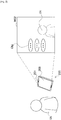
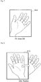
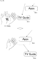
- Fig. 1 is a diagram useful in explaining an overview of an information processing apparatus 100 according to a first embodiment of the present disclosure.
- the information processing apparatus 100 is a television apparatus.
- the information processing apparatus 100 includes a camera 101, a microphone 102, and a display 108.
- the camera 101 picks up images of users who are looking at the display 108 of the information processing apparatus 100.
- the microphone 102 picks up voice samples produced by such users.
- the display 108 displays images generated by the information processing apparatus 100.
- the images displayed by the display 108 may include user interface (UI) images in addition to content images.
- UI user interface
- the UI image W01 is generated using a picked-up image picked up by the camera 101 and realizes a so-called "mirror image" display.
- a plurality of UI objects Obj are superimposed on the UI image W01.
- the users Ua and Ub may interact with the information processing apparatus 100 by operating the UI objects Obj via various gestures using their bodies.
- a voice command inputted via the microphone 102 into the information processing apparatus 100 may also be used to supplement interaction with the information processing apparatus 100.
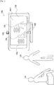
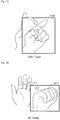
- Fig. 2 is a diagram useful in explaining an overview of an information processing apparatus 200 according to a second embodiment of the present disclosure.
- the information processing apparatus 200 is a tablet PC.
- the information processing apparatus 200 includes a camera 201, a microphone 202, and a display 208.
- the camera 201 picks up images of users who are looking at the display 208 of the information processing apparatus 200.
- the microphone 202 picks up voice samples produced by such users.
- the display 208 displays images generated by the information processing apparatus 200.
- the images displayed by the display 208 may include user interface (UI) images in addition to content images.
- UI user interface
- the UI image W02 is generated using a picked-up image picked up by the camera 201 and realizes a so-called "mirror image" display.
- a plurality of UI objects Obj are also superimposed on the UI image W02.
- the user Uc may interact with the information processing apparatus 200 by operating the UI objects Obj via various gestures that use the body.
- the UI objects operated by the user may be automatically laid out in the vicinity of the head or hand of the user in the image.
- the screen region in the vicinity of the head or hand of the user is limited, when a plurality of UI objects are provided, there is the risk of such UI objects being congested in the vicinity of the user. If the UI objects are congested in a limited screen region, it becomes difficult to select the individual UI objects, which can conversely cause a drop in usability. For this reason, the information processing apparatuses 100 and 200 avoid such drop in usability in accordance with the framework described in detail in the following sections.
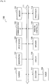
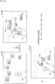
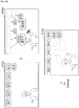
- Fig. 3 is a block diagram showing an example hardware configuration of the information processing apparatus 100.
- the information processing apparatus 100 includes the camera 101, the microphone 102, an input device 103, a communication interface (I/F) 104, a memory 105, a tuner 106, a decoder 107, a display 108, a speaker 109, a remote control I/F 110, a bus 111, and a processor 112.
- I/F communication interface
- the camera 101 includes an image pickup element such as a CCD (Charge Coupled Device) or a CMOS (Complementary Metal Oxide Semiconductor) and picks up images.
- the images picked up by the camera 101 (frames that construct video) are treated as input images for processing by the information processing apparatus 100.
- the microphone 102 picks up a voice sample produced by a user and generates a voice signal.
- the voice signal generated by the microphone 102 is able to be treated as an input voice intended for voice recognition by the information processing apparatus 100.
- the microphone 102 may be an omnidirectional microphone or a microphone with fixed or variable directionality.
- the input device 103 is a device used by the user to directly operate the information processing apparatus 100.
- the input device 103 may include buttons, switches, dials, and the like disposed on the housing of the information processing apparatus 100.
- the input device 103 On detecting a user input, the input device 103 generates an input signal corresponding to the detected user input.
- the communication I/F 104 acts as an intermediary for communication between the information processing apparatus 100 and another apparatus.
- the communication I/F 104 supports an arbitrary wireless communication protocol or wired communication protocol and establishes a communication connection with the other apparatus.
- the memory 105 is constructed of a storage medium such as a semiconductor memory or a hard disk drive and stores programs and data for processing by the information processing apparatus 100, as well as content data.
- the data stored by the memory 105 may include characteristic data used for image recognition and voice recognition, described later. Note that some or all of the programs and data described in the present specification may not be stored by the memory 105 and instead may be acquired from an external data source (as examples, a data server, network storage, or an externally-attached memory).
- the tuner 106 extracts and demodulates a content signal on a desired channel from a broadcast signal received via an antenna (not shown). The tuner 106 then outputs the demodulated content signal to the decoder 107.
- the decoder 107 decodes content data from the content signal inputted from the tuner 106.
- the decoder 107 may decode content data from a content signal received via the communication I/F 104.
- Content images may be generated based on the content data decoded by the decoder 107.
- the display 108 has a screen constructed of an LCD (Liquid Crystal Display), an OLED (Organic Light-Emitting Diode), a CRT (Cathode Ray Tube), or the like and displays images generated by the information processing apparatus 100.
- LCD Liquid Crystal Display
- OLED Organic Light-Emitting Diode
- CRT Cathode Ray Tube
- content images and UI images that were described with reference to Figs. 1 and 2 may be displayed on the screen of the display 108.
- the speaker 109 has a diaphragm and circuit elements such as an amplifier and outputs audio based on an output voice signal generated by the information processing apparatus 100.
- the volume of the speaker 109 is variable.
- the remote control I/F 110 is an interface that receives a remote control signal (an infrared signal or other wireless signal) transmitted from a remote controller used by the user. On detecting a remote control signal, the remote control I/F 110 generates an input signal corresponding to the detected remote control signal.
- a remote control signal an infrared signal or other wireless signal
- the bus 111 connects the camera 101, the microphone 102, the input device 103, the communication I/F 104, the memory 105, the tuner 106, the decoder 107, the display 108, the speaker 109, the remote control I/F 110, and the processor 112 to each other.
- the processor 112 may be a CPU (Central Processing Unit) or a DSP (Digital Signal Processor). By executing a program stored in the memory 105 or on another storage medium, the processor 112 causes the information processing apparatus 100 to function in various ways as described later.
- CPU Central Processing Unit
- DSP Digital Signal Processor
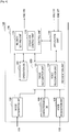
- Fig. 4 is a block diagram showing an example configuration of logical functions realized by the memory 105 and the processor 112 of the information processing apparatus 100 shown in Fig. 3 .
- the information processing apparatus 100 includes an image acquisition unit 120, a voice acquisition unit 130, an application unit 140, a recognition unit 150, a characteristics database (DB) 160, a control unit 170, and an operation DB 180.
- the recognition unit 150 includes an image recognition unit 152 and a voice recognition unit 154.
- the control unit 170 includes an operation control unit 172 and a priority setting unit 174.
- the image acquisition unit 120 acquires an image picked up by the camera 101 as an input image.
- the input image is typically an individual frame in a series of frames that construct video in which users appear.
- the image acquisition unit 120 then outputs the acquired input image to the recognition unit 150 and the control unit 170.
- the voice acquisition unit 130 acquires the voice signal generated by the microphone 102 as an input voice.
- the voice acquisition unit 130 then outputs the acquired input voice to the recognition unit 150. Note that processing of an input voice may be omitted from the present embodiment.
- the application unit 140 carries out various application functions of the information processing apparatus 100. As examples, a television program reproduction function, an electronic program guide display function, a recording setting function, a content reproduction function, a content searching function, and an Internet browsing function may be carried out by the application unit 140.
- the application unit 140 outputs application images (which may include content images) and audio which have been generated via the application function to the control unit 170.
- At least some of the processes carried out by the application unit 140 are associated with UI objects laid out on a UI image. Such processes may be carried out in response to operation events that involve the associated UI objects.
- the processes that may be carried out via UI objects may include arbitrary processes, such as setting a channel and volume for a television program reproduction function, setting a channel and time period for an electronic program guide display function, selecting content for a content reproduction function, and designating a search keyword and carrying out a search for a content search function.
- the image recognition unit 152 recognizes an operation object used by the user in an input image inputted from the image acquisition unit 120.
- the operation object is the user's hand.
- a user's hand that makes a specified shape (such as a shape where the hand is open, a gripping shape, or a shape of pointing with a finger) may be used as the operation object.
- the user's foot or a known actual object held by the user may be used as the operation object.
- the image recognition unit 152 may recognize the hand region in the input image by matching image characteristic values extracted from the input image and image characteristic values an operation object stored in advance by the characteristics DB 160. In the same way, the image recognition unit 152 may recognize a face region in the input image.
- Fig. 5 is a diagram useful in explaining one example of the result of image recognition by the image recognition unit 152.
- the user Ua appears in the input image W03.
- the user Ua is facing the camera 101 and raising his left hand.
- the image recognition unit 152 is capable of recognizing a hand region A01 and a face region A02 in the input image W03.
- the image recognition unit 152 then outputs position data showing the positions in the image of such recognized regions to the control unit 170.
- the image recognition unit 152 may identify the user by matching an image part (facial image) of the face region recognized in an input image against facial image data of known users stored in advance by the characteristics DB 160.
- the user identification result produced by the image recognition unit 152 can be used to personalize menus displayed in a UI image, or by the application unit 140 to recommend content, and to make adjustments to the voice recognition.
- the image recognition unit 152 also recognizes gestures of the users appearing in an input image.
- the image recognition unit 152 recognizes a gesture G0 by monitoring movement of a hand region A01 of the user.
- the gesture G0 is a gesture ("Hand Up") of raising the hand.
- the expression “gestures” is assumed to also include static “poses” (forms) that do not involve dynamic movement of the user's body.
- the image recognition unit 152 outputs gesture data showing the recognized type of gesture to the control unit 170.
- Example of gestures that can be recognized by the image recognition unit 152 will now be described with reference to Figs. 6 to 12 .
- a hand region A11 is shown.
- the hand region A11 is being waved to the left and right at short intervals. From such movement of the user's hand, the image recognition unit 152 can recognize a gesture G1.
- the gesture G1 is a gesture ("Waving") of waving the hand.
- a hand region A12 is shown.
- the hand region A12 is substantially stationary in the input image for a specific length of time. From such stationary state of the user's hand, the image recognition unit 152 can recognize a gesture G2.
- the gesture G2 (“Keep Still") is a gesture of keeping the hand still.
- a hand region A13 is shown.
- the user's hand appearing in the hand region A13 is rotating in the counterclockwise direction around a center point in a vicinity of the wrist. From such movement of the user's hand, the image recognition unit 152 can recognize a gesture G3a.
- the gesture G3a (“Rotation") is a gesture of rotating the hand.
- a hand region A14 is shown.
- the user's hand appearing in the hand region A14 is in a shape where fingers aside from the index finger are bent over and the hand is rotating in the counterclockwise direction around a center point in a vicinity of the wrist. From such movement of the user's hand, the image recognition unit 152 recognizes a gesture G3b.
- the gesture G3b (“Rotation") is also a gesture of rotating the hand.
- a hand region A15 is shown.
- the hand of the user appearing in the hand region A15 is moving so as to bend the wrist to the right. From such movement of the user's hand, the image recognition unit 152 can recognize a gesture G4a.
- the gesture G4a (“Touch") is a gesture of touching an object.
- a hand region A16 is shown.
- the hand of the user appearing in the hand region A16 is moving so as to bend the wrist forward with the hand in a shape where all of the fingers aside from the index finger are bent over. From such movement of the user's hand, the image recognition unit 152 can recognize a gesture G4b.
- the gesture G4b (“Touch") is also a gesture of touching an object.
- a hand region A17 is shown.
- the hand of the user appearing in the hand region A17 is changing from a shape where the palm of the hand is open to a shape where the palm is closed. From such movement of the user's hand, the image recognition unit 152 can recognize a gesture G5.
- the gesture G5 (“Grasp") is also a gesture of grasping an object.
- gestures described here are mere examples. It is not necessary for the image recognition unit 152 to recognize a number of such gestures and/or the image recognition unit 152 may additionally recognize other types of gestures.
- the voice recognition unit 154 carries out voice recognition on the voice of the user based on an input voice inputted from the voice acquisition unit 130. If, for example, an application being carried out or a UI receives the inputting of a voice command, the voice recognition unit 154 recognizes a voice command from the user's voice and outputs an identifier of the recognized voice command to the application unit 140 or the control unit 170.
- the characteristics DB 160 stores in advance image characteristics data which is to be used in image recognition by the image recognition unit 152.
- the image characteristics data may include known image characteristic values for an operation object (such as the hand) used by the user and the face of the user.
- the image characteristics data may also include facial image data for each user.
- the image characteristics data may also include gesture definition data defining gestures to be recognized by the image recognition unit 152.
- the characteristics DB 160 may also store in advance voice characteristics data to be used for voice recognition by the voice recognition unit 154.
- the operation control unit 172 generates a UI image by superimposing at least one UI object on the input image, and displays a generated UI image (an output image corresponding to the input image) on the screen of the display 108.
- the input image for generating the UI image may differ to the input image to be used by the image recognition unit 152 for recognizing the operation object (as one example, an image with reduced resolution may be used to recognize the operation object).
- the operation control unit 172 then controls the displaying and operation of at least one UI object based on the recognition result of the operation object inputted from the image recognition unit 152.
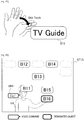
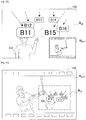
- Fig. 13 is a diagram useful in explaining a first example of UI objects.
- the UI objects are menu items of an application menu.
- a UI image W04 includes UI objects B11 to B16.
- the UI object B11 is a menu item (Volume) for setting the volume when reproducing a television program.
- the UI object B12 is a menu item (Channel) for setting the channel to be reproduced.
- the UI object B13 is a menu item (TV Guide) for launching an electronic program guide display function.
- the UI object B14 is a menu item (Apps) for launching other application functions.
- the UI object B15 is a menu item (Internet) for launching an Internet browsing function.
- the UI object B16 is a menu item (Settings) for launching an appliance setting function of the information processing apparatus 100.
- menu items may be defined in a hierarchy, and as one example subitems "Increase volume” and "Decrease volume” may be present below a UI object B11 that is the menu item for setting volume. If individual users are identified using input images, a set of UI objects that are personalized for individual users may be displayed.
- Fig. 14 is a diagram useful in explaining a second example of UI objects.
- the UI objects are content items.
- a UI image W05 includes UI objects B21 to B26.
- the UI objects B21 to B26 respectively express thumbnails of photographic content.
- the UI objects may be other types of content items, such as video content, music content, or text content.
- the operation control unit 172 lays out the UI objects at default display positions.
- the default display positions may be positions provided so as to be fixed or may be positions that move (as one example, that move so as to float) in accordance with some type of algorithm.
- the operation control unit 172 then causes the display positions of at least one UI object displayed before recognition of the operation object to approach toward the user after recognition of the operation object.
- the operation control unit 172 may cause the display position of a UI object to approach toward the recognized operation object or to approach toward part of the body of a different user to the recognized operation object.
- a position of the UI-object is spatially related to the recognized operation object since it is moved toward the recognized operation object, such as the user's hand.
- the mode of approach of UI objects toward the user is uniform. That is, the operation control unit 172 sets the approach speeds of the UI objects that are to make the approach at the same value so that such UI objects all approach toward the user at the same approach speed.
- the mode of approach of UI objects toward the user is non-uniform. That is, the operation control unit 172 sets the approach speeds of the UI objects that are to make the approach at different values so that the UI objects approach toward the user at different approach speeds.
- other attributes of the UI objects may be set non-uniformly. As examples, such other attributes may include at least one of approach start timing, post-approach display positions (hereinafter referred to as the "target positions"), display size, transparency, and depth.
- the operation control unit 172 may vary the mode of approach of the respective objects in accordance with priorities set for the respective objects.
- priorities are set in advance by the priority setting unit 174 in accordance with a specific priority setting standard and stored by an operation DB 180.
- a first example of the priority setting standard is a standard relating to an operation history of the UI objects.
- the priorities may be set higher for UI objects with a higher operation frequency (the number of past operations per specific period) and the priorities may be set lower for UI objects with a lower operation frequency. It is also possible to set the priority higher for UI objects that were operated at more recent timing in the past.
- a second example of a priority setting standard is a standard relating to user attributes.
- the priorities of UI objects corresponding to content items with a high recommendation score calculated according to a known recommendation technology based on the user attributes may be set at higher values.
- the operation control unit 172 may provide the user with a UI for switching the priority setting standard at desired timing between a plurality of candidates.
- Such UI may be realized by any method such as user gestures or voice commands.
- the operation control unit 172 sets the approach speed and other attributes of the UI objects so as to make objects that have higher priorities easier to operate for the user. More specifically, as one example, the operation control unit 172 may set the approach speed toward the user higher for objects with higher priorities. The operation control unit 172 may also set the approach start timing of objects earlier for objects with higher priorities. Also, for an object with higher priority, the operation control unit 172 may set the target position closer to the user, the display size larger, the transparency lower, or the depth shallower.
- the operation control unit 172 controls operations of UI objects by the user in response to a number of operation events defined in advance.
- the operation events typically include recognition of a user gesture, and recognition of voice commands may be used to complement such recognition.
- At least one operation event is recognition of a new operation object. Recognition of a new operation object may trigger UI objects approaching toward the user. Another operation event may trigger execution (launching) of a process associated with a UI object.
- the operation control unit 172 also controls the displaying of a UI image via the display 108.
- the operation control unit 172 may display only an UI image on which UI objects are superimposed on the screen of the display 108.
- the operation control unit 172 may display a single output image generated by combining a UI image and an application image generated by the application unit 140 on the screen. A number of examples of window compositions of output images that can be used in the present embodiment are described later.
- the priority setting unit 174 sets the priority of each UI object in accordance with the priority setting standard described earlier. As one example, in accordance with a priority setting standard relating to the operation histories of UI objects, the priority setting unit 174 may set the priorities higher for UI objects with a higher operation frequency. Also, in accordance with a priority setting standard relating to user attributes, the priority setting unit 174 may set the priorities higher for UI objects corresponding to content items with a higher recommendation score. The priority setting unit 174 may also set the priorities of UI objects randomly to add an element of surprise to the UI. The priority setting unit 174 may update the priority data for example when a UI object has been operated or when the user attributes have changed.
- the operation DB 180 stores data used by the operation control unit 172 to control displaying and operations of UI objects.
- the data stored by the operation DB 180 includes object data showing a default display position and default values of other attributes for each UI object.
- the data stored by the operation DB 180 may also include priority data showing priorities set by the priority setting unit 174, operation history data showing an operation history for each user, and user data showing attributes (such as age, sex, occupation, and tastes) for each user.
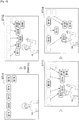
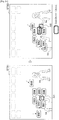
- Fig. 15 is a diagram useful in explaining a first example of a mode of approach toward the user of UI objects.
- the mode of approach of the UI objects is uniform. After sufficiently approaching the user, the respective UI objects move away from the vicinity of the user without remaining at such target positions.
- UI images ST11 to ST14 are shown along a time axis.
- a user Ud appears in the UI image ST11 and a mirror image display is realized.
- UI objects B11 to B16 are laid out at default display positions. It is assumed here that as a result of the user Ud raising his hand, the image recognition unit 152 recognizes the gesture G0.
- the operation control unit 172 causes the UI objects B11 to B16 to start approaching toward the user Ud (as one example, the hand that is the operation object of the user Ud).
- the UI object B13 is positioned closest to the user Ud.
- the UI object B13 returns to the default display position and in place of the UI object B13, the UI objects B12 and B14 are positioned in the vicinity of the user Ud's hand.
- the UI objects B12 and B14 return to the default display positions and in place of the UI objects B12 and B14, the UI objects B11, B15 and B16 are positioned in the vicinity of the user Ud's hand.
- Fig. 16 is a diagram useful in explaining a second example of a mode of approach toward the user of UI objects.
- the mode of approach of the UI objects is non-uniform. After sufficiently approaching the user, the respective UI objects remain at their target positions.
- UI images ST21 to ST24 are shown along a time axis.
- the user Ud appears in the UI image ST21 and a mirror image display is realized.
- UI objects B11 to B16 are laid out at default display positions. It is assumed here that as a result of the user Ud raising his hand, the image recognition unit 152 recognizes the gesture G0.
- the operation control unit 172 causes the UI objects B11 to B16 to start approaching toward the user Ud.
- the UI object B13 is positioned closest to the user Ud.
- the UI object B13 remains at its target position and the UI objects B12 and B14 also reach the vicinity of the user Ud's hand.
- the UI objects B12, B13, and B14 remain at their target positions and the UI objects B11, B15 and B16 also reach the vicinity of the user Ud's hand.
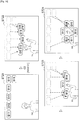
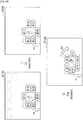
- Fig. 17 is a diagram useful in explaining a third example of a mode of approach toward the user of UI objects.
- the mode of approach of the UI objects is non-uniform and the operation control unit 172 sets the approach speeds of the UI objects that are to make an approach at different values.
- UI images ST31 to ST33 are shown along a time axis.
- the user Ud appears in the UI image ST31 and a mirror image display is realized.
- the UI objects B11 to B16 are laid out at default display positions. It is assumed here that as a result of the user Ud raising his hand, the image recognition unit 152 recognizes the gesture G0.
- the operation control unit 172 sets the respective approach speeds V 11 to V 16 of the UI objects B11 to B16 in accordance with the priorities set by the priority setting unit 174.
- priorities that were set by the priority setting unit 174 in accordance with a priority setting standard relating to the operation histories of the respective UI objects are used by the operation control unit 172.
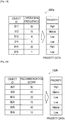
- Fig. 19 is a diagram useful in explaining an example of priority data corresponding to the third example in Fig. 17 .
- priority data 182a includes three data items, namely "object ID", “operation frequency”, and "priority".
- object ID is an identifier for uniquely identifying each UI object.
- operation frequency shows the number of past operations per specific period (for example, one week, one day, or a few hours) of each UI object.
- priority shows a priority set for each UI object.
- the priority is set at one of three levels, namely "High", “Middle” and “Low”. In the example in Fig.
- the operation frequencies of the UI objects B11 and B15 are the first and second highest, and accordingly the priorities of the UI objects B11 and B15 are set at High.
- the operation frequency of the UI object B12 is the third highest, and accordingly the priority of the UI object B12 is set at Middle.
- the priorities of the remaining UI objects B13, B14, and B16 are set at Low.
- the operation control unit 172 refers to such priority data 182a and sets the approach speeds V 11 and V 15 of the UI objects B11 and B15 at the fastest speed, the approach speed V 12 of the UI object B12 at next fastest speed, and the approach speeds V 13 , V 14 , and V 16 of the UI objects B13, B14, and B16 at the slowest speed.
- the UI objects B11 and B15 reach the vicinity of the user Ud's hand the earliest.
- Fig. 18 is a diagram useful in explaining a fourth example of a mode of approach toward the user of UI objects.
- the mode of approach of the UI objects is non-uniform and the operation control unit 172 sets the approach speeds of the UI objects that are to make an approach at different values.
- UI images ST41 to ST43 are shown along a time axis.
- the user Ud appears in the UI image ST41 and a mirror image display is realized.
- the UI objects B21 to B26 are laid out at default display positions. It is assumed here that as a result of the user Ud raising his hand, the image recognition unit 152 recognizes the gesture G0.
- the operation control unit 172 sets the respective approach speeds V 21 to V 26 of the UI objects B21 to B26 in accordance with the priorities set by the priority setting unit 174.
- priorities that were set by the priority setting unit 174 in accordance with a priority setting standard relating to user attributes are used by the operation control unit 172.
- Fig. 20 is a diagram useful in explaining an example of priority data corresponding to the fourth example in Fig. 18 .
- priority data 182b includes three data items, namely "object ID", “recommendation score”, and "priority”.
- object ID is an identifier for uniquely identifying each UI object.
- the "recommendation score” shows a recommendation score calculated (by an arbitrary known recommendation algorithm) based on attributes of the user and information relating to content.
- the "priority” shows a priority set for each UI object.
- it is assumed that the priority is set at one of three levels, namely "High", “Middle” and “Low”. In the example in Fig.
- the recommendation score of the UI object B21 is the highest, and accordingly the priority of the UI object B21 is set at High.
- the recommendation scores of the UI objects B22 and B25 are the second and third highest, and accordingly the priorities of the UI objects B22 and B25 are set at Middle.
- the priorities of the remaining UI objects B23, B24, and B26 are set at Low.
- the operation control unit 172 refers to such priority data 182b and sets the approach speed V 21 of the UI object B21 at the fastest speed, the approach speeds V 22 and V 25 of the UI objects B22 and B25 at the next fastest speed, and the approach speeds V 23 , V 24 , and V 26 of the UI objects B23, B24 and B26 at the slowest speed.
- the UI object B21 has reached the vicinity of the user Ud's hand the earliest.
- the UI object B21 (and the following UI objects B22, B25) is not operated by the user Ud, in the next UI image ST43, the UI objects B23, B24, and B26 that have a slow approach speed may reach the vicinity of the user Ud.
- Fig. 21 is a diagram useful in explaining a fifth example of a mode of approach toward the user of UI objects.
- the mode of approach of the UI objects is non-uniform and the operation control unit 172 sets the approach speeds of the UI objects that are to make an approach at different values.
- the operation control unit 172 also sets the display sizes of the UI objects to make an approach at different values.
- UI images ST51 to ST53 are shown along a time axis.
- the user Ud appears in the UI image ST51 and a mirror image display is realized.
- the UI objects B11 to B16 are laid out at default display positions. It is assumed here that as a result of the user Ud raising his hand, the image recognition unit 152 recognizes the gesture G0.
- the operation control unit 172 sets the respective approach speeds and display sizes of the UI objects B21 to B26 in accordance with the priorities set by the priority setting unit 174. In the example in Fig. 21 , it is assumed that the priority data 182a illustrated in Fig. 19 is used.
- the operation control unit 172 refers to such priority data 182a and sets the approach speeds V 11 and V 15 of the UI objects B11 and B15 at the fastest speed, the approach speed V 12 of the UI object B12 at the next fastest speed, and the approach speeds V 13 , V 14 , and V 16 of the UI objects B13, B14 and B16 at the slowest speed.
- the operation control unit 172 also sets the display size of the UI objects B11 and B15 the largest, the display size of the UI object B12 the next largest, and the display sizes of the UI objects B13, B14 and B16 the smallest.
- the UI objects B11 and B15 have larger display sizes that the other UI objects.
- Fig. 22 is a diagram useful in explaining a first example of an operation event.
- the user's hand that is the operation object and a UI object B13 are shown.
- the image recognition unit 152 can recognize the gesture G4b of touching an UI object.
- the operation control unit 172 can determine that the UI object B13 has been designated (that is, touched). If the position of the hand region coincides with the display position of the same UI object for a specified length of time, the operation control unit 172 may also determine that such UI object is designated.
- the operation control unit 172 causes the application unit 140 to carry out a process associated with the designated UI object B13.
- the UI object B13 is a menu item for launching an electronic program guide display function
- an electronic program guide can be then displayed on the screen by the application unit 140.
- the user is capable of remotely controlling the information processing apparatus 100 even when a remote controller is not at hand.
- the user since the only movement necessary by the user is a simple gesture, the user is capable of having the information processing apparatus 100 carry out a desired process (for example, a menu process or an application process) without feeling stress.
- the process associated with a UI object may be a process for UI control. For example, opening a submenu item from the designated menu item, calling a setting screen corresponding to the designated menu item, and the like may be carried out in response to recognition of a gesture of touching a UI object.
- Fig. 23 is a diagram useful in explaining a second example of an operation event.
- the operation control unit 172 determines that the UI object B16 has been designated by the user Ud.
- a specific voice command VR1 issued by the user has been recognized by the voice recognition unit 154.
- the voice command VR1 corresponds to a voice input of "Go!”.
- the operation control unit 172 causes the application unit 140 to carry out a process associated with the designated UI object B16 in response to an operation event corresponding to recognition of the voice command VR1 by the voice recognition unit 154.
- the operation control unit 172 sets display attributes (for example, at least one of texture, color, transparency, display size, and depth) of the designated UI object B16 at different attribute values to other UI objects. By doing so, it is possible for the user to grasp that the UI object B16 was appropriately designated.
- display attributes for example, at least one of texture, color, transparency, display size, and depth
- Fig. 24 is a diagram useful in explaining a third example and a fourth example of operation events.
- the UI image ST24 shown in Fig. 16 and following UI images S25 and ST26 are also shown.
- the UI image ST24 the UI objects B11 to B16 have display positions laid out in a ring in the vicinity of the user Ud's hand that is the operation object.
- the image recognition unit 152 may recognize the gesture G2 of keeping the hand still from movement of the user's hand where the hand remains substantially still in the input image for a specific length of time.
- the operation control unit 172 stops the movement on the screen of the UI objects B11 to B16 in response to an operation event corresponding to recognition of the gesture G2.
- the display positions of the UI objects B11 to B16 are not updated.
- the image recognition unit 152 may recognize the gesture G3a of rotating the hand from a movement where the user Ud's hand, which is operation object, rotates.
- the operation control unit 172 rotates (in the direction D1 in the image) the display positions of the UI objects B11 to B16 around a reference point in the image.
- the reference point referred to here may be a center of gravity of the hand region, a center of the UI objects B11 to B16, or any other arbitrary point.
- the user can move the display positions of UI objects that have approached the vicinity of the user to positions that is easier to handle.
- the display positions of the UI objects may move in parallel in response to movement of the user's hand. Note that instead of all of the displayed UI objects rotating or moving as shown in the example in Fig. 24 , only some of the UI objects may be rotated or moved. As one example, at least one UI object to be rotated or moved may be designated by a gesture of the user tracing the UI objects with his/her hand.
- Fig. 25 is a diagram useful in explaining a fifth example of an operation event.
- the user's hand that is the operation object is shown together with the UI objects B13 and B14.
- the image recognition unit 152 may recognize the gesture G1 of waving the hand from a movement where the user's hand is waved to the left and right.
- the operation control unit 172 can determine that the UI object B13 has been designated.
- the operation control unit 172 moves the display position of the designated UI object B13 away from the user.
- the display position of the UI object B13 is moved away from the user and in place of the UI object B13 the UI object B14 approaches the user's hand.
- Fig. 26 is a diagram useful in explaining a sixth example of an operation event.
- the UI images ST51 and ST52 shown in Fig. 21 and a following UI image ST54 are shown along a time axis.
- the user Ud appears in the UI image ST51 and a mirror image display is realized.
- the UI objects B11 to B16 are also laid out at default display positions.
- the UI objects B11 to B16 are objects belonging to a first category out of a plurality of categories defined in advance.
- the first category is a category relating to a television program reproduction function.
- UI objects are not necessarily visible to the user.
- UI objects may be positioned outside the screen, or may be transparent or translucent.
- the UI objects may change from a non-active state (undisplayed or translucent) to an active state (displayed or non-transparent) at timing where the user raises his/her hand.
- a UI image ST52 As a result of the user Ud raising his hand, the UI objects B11 to B16 start to approach the user Ud.
- the image recognition unit 152 may recognize the gesture G1 of waving the hand from a movement where the user's hand is waved to the left and right.
- the operation control unit 172 replaces the objects B11 to B 16 laid out in the UI image with the UI objects belonging to a second category.
- the second category may be an arbitrary category (such as a category relating to a content reproduction function) that differs to the first category.
- the objects B11 to B16 are removed from the screen and new UI objects B31 to B37 are laid out on the screen.
- the information processing apparatus 100 is capable of displaying only some of the UI objects on the screen without displaying all of the UI object candidates that can be displayed on the screen. Accordingly, crowding of the screen region is significantly eased. It is also possible for the user to have a desired UI object, which is not presently displayed at such time, displayed on the screen via a simple gesture and to appropriately operate such UI object.
- selection of the category of UI objects to be displayed in an UI image may depend on the shape of the user's hand.
- the UI objects that have been displayed so far may be replaced with UI objects that belong to any of the first to fifth categories in response to recognition of five types of hand shape that respectively express the numbers one to five.
- the gesture G1 may be defined as not as a gesture for switching the category of UI objects to be displayed but as a gesture for switching the priority setting standard used to set the approach speeds.
- the operation control unit 172 in response to the operation event corresponding to the recognition of the gesture G1, resets the priorities of at least one of the UI objects being displayed in accordance with the new priority setting standard.
- Fig. 27 is a diagram useful in explaining a seventh example and an eighth example of operation events.
- the UI image ST42 shown in Fig. 18 and following UI images ST44, ST45, and ST46 are shown along a time axis.
- the user Ud appears in the UI image ST42 and is raising his hand.
- the UI objects B21 to B26 are approaching toward the user Ud at approach speeds respectively set by the operation control unit 172.
- the image recognition unit 152 may recognize the gesture G5 of grasping an object from a movement of the user's hand that changes from a shape where the palm of the hand is open to a shape where the hand is closed.
- the operation control unit 172 may determine that the UI object B25 is designated (that is, grasped).
- the operation control unit 172 thereafter has the display position of the designated UI object B25 track the position of the hand region (that is, has the UI object B25 move together with the operation object).
- UI objects aside from the designated UI object B25 are removed.
- two screen regions R11 and R12 are set in the image.
- the operation control unit 172 may set an equal number of screen regions to the number of processes associated with the designated UI object B25.
- the screen region R11 may be associated with launching an image viewer and the screen region R12 may be associated with transmitting a message to which photographic content is appended.
- the display position of the UI object B25 also moves to a position that coincides with the screen region R12.
- the operation control unit 172 causes the application unit 140 to carry out a process associated with the UI object B25.
- a message transmission function is launched by the application unit 140 and photographic content may be appended to a new message.
- Fig. 28 is a diagram useful in explaining a ninth example of an operation event.
- the four UI images ST61 to ST64 are shown along a time axis.
- the user Ud appears in the UI image ST61 and a mirror image display is realized.
- the UI objects B11 to B16 are also laid out at default display positions.
- the UI objects B11 to B16 are objects belonging to a first category out of a plurality of categories defined in advance.
- the first category is a category relating to a television program reproduction function.
- four screen regions R21 to R24 are set in the image.
- the screen regions R21 to R24 may be associated with respectively different categories.
- the UI objects B11 to B16 start to approach toward the user Ud.
- the position of the user Ud's hand coincides with the screen region R23. It is assumed that the screen region R23 is associated with the first category.
- the position of the user Ud's hand region coincides with the screen region R24. It is assumed that the screen region R24 is associated with a different category to the first category.
- the objects B11 to B16 laid out in the UI image are replaced with objects belonging to another category.
- the objects B11 to B16 are removed from the screen and new UI objects B41 to B45 are laid out in the image.
- the UI objects B41 to B45 start to approach toward the user Ud.
- the information processing apparatus 100 is capable of displaying only some of the UI objects on the screen instead of all of the UI object candidates that can be displayed. Accordingly, crowding of the screen region is significantly eased. It is also possible for the user to have desired UI objects that are not on display at the present time displayed on the screen via a simple operation of simply moving the hand and to appropriately operate such UI objects.
- Fig. 29 is a diagram useful in explaining a first example of an operation scenario involving a plurality of operation objects.
- the left hand and the right hand of a single user are recognized as separate operation objects.
- UI images ST71 to ST74 are shown along a time axis.
- UI objects B51 to B58 are laid out at default display positions. It is assumed here that the UI objects B51 to B58 are grouped into a plurality of groups in accordance with a grouping standard. As examples, the UI objects may be grouped according to a standard relating to the priorities described earlier, the types of corresponding menu items or content items, or display positions, or may be randomly grouped.
- the operation control unit 172 causes the UI objects B53 to B56 included in the first group to start approaching toward the user Ud.
- the operation control unit 172 causes the UI objects B51, B52, B57, and B58 included in the second group to start approaching toward the user Ud.
- the UI objects B53 to B56 are laid out in a ring in the vicinity of the user Ud's left hand and the UI objects B51, B52, B57, and B58 are laid out in a ring in the vicinity of the user Ud's right hand.
- the operation control unit 172 may form a single ring by merging the two rings of such UI objects. If the hand regions are positioned at edge portions of the screen, the operation control unit 172 may distort the shapes of the rings.
- Fig. 30 is a diagram useful in explaining a second example of an operation scenario involving a plurality of operation objects.
- the hands of two users are recognized as separate operation objects.
- Fig. 30 two UI images ST81 to ST82 are shown along a time axis.
- the user Ud and a user Ue appear in the UI image ST81 and a mirror image display is realized.
- UI objects B61 to B68 are also displayed.
- the user Ud raises his left hand and a hand region A21 is recognized.
- the UI objects B61 to B68 are approaching toward the user Ud.
- the operation control unit 172 has the UI objects B61, B64, B65 and B68 start to approach toward the user Ue.
- the UI objects may be grouped into a plurality of groups in accordance with a grouping standard relating to an operation history for each user or user attributes. In the example in Fig. 30 , although the UI objects B62, B63, B66 and B67 are included in a first group intended for the user Ud, the UI objects B61, B64, B65 and B68 are included in a second group intended for the user Ue.
- the operation control unit 172 expresses that the UI objects B61, B64, B65 and B68 are included in the second group intended for the user Ue. If the target positions of the two groups interfere with one another, the operation control unit 172 may shift the target positions to eliminate such interference.
- display attributes for example, color
- the fifth example of an operation event described with reference to Fig. 25 may be defined as an operation event of passing a UI object to another user, with it being possible to use such operation in this operation scenario.
- Fig. 31 is a diagram useful in explaining a third example of an operation scenario involving a plurality of operation objects.
- the hands of two users are recognized as separate operation objects.
- UI image ST81 shown in Fig. 30 and a following UI image ST83 are shown along a time axis.
- the user Ud and the user Ue appear in the UI image ST81 and a mirror image display is realized.
- the UI objects B61 to B68 are also displayed.
- the user Ud raises his left hand and a hand region A21 is recognized.
- the UI objects B61 to B68 continue to approach toward the user Ud.
- the operation control unit 172 may determine that the UI object B65 is designated. In response to such operation event, the operation control unit 172 has the application unit 140 carry out a process associated with the designated UI object B65.
- UI objects are two-dimensionally laid out in a UI image have mainly been described so far.
- the respective UI objects are not limited to having two-dimensional display positions and may have an attribute corresponding to depth. If the information processing apparatus 100 is capable of recognizing the distance between a camera and an operation object using a known method such as parallax, the operation control unit 172 may determine which UI object has been designated by the user also based on such recognized distance.
- Figs. 32 and 33 show examples of the window composition of output images that may be used by the present embodiment.
- a UI window W UI and an application window W APP are displayed by the display 108.
- the UI window W UI displays a UI image generated by the operation control unit 172.
- the application window W APP displays an application image (for example, a content image) inputted from the application unit 140.
- the application window W APP is combined at the bottom right corner of the UI window W UI .
- the UI window W UI is blended with one part of the application window W APP .
- FIGs. 34 and 35 show an example of the flow of processing that may be carried out by the information processing apparatus 100 according to the present embodiment.
- the processing described here is repeated for each frame in a series of frames that construct video picked up by the camera 101.
- the image acquisition unit 120 acquires an image picked up by the camera 101 as an input image (step S100).
- the image acquisition unit 120 then outputs the acquired input image to the recognition unit 150 and the control unit 170.
- the image recognition unit 152 recognizes the operation object appearing in the input image inputted from the image acquisition unit 120 (step S105). It is assumed here that the operation object is the user's hand. For example, the image recognition unit 152 recognizes a hand region in the input image and outputs position data showing the position of such recognized hand region to the control unit 170. The image recognition unit 152 also recognizes a user gesture based on movement of the hand region. In addition, a voice command may also be recognized by the voice recognition unit 154 based on an input voice.
- the operation control unit 172 determines an operation event based on an image recognition result inputted from the image recognition unit 152 and a voice recognition result that may be inputted as necessary from the voice recognition unit 154 (step S110).
- the subsequent processing branches in accordance with the operation event determined here.
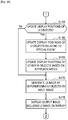
- step S115 the operation control unit 172 determines whether a new set of UI objects is to be displayed (step S115). As examples, if a UI image is to be newly displayed or if the operation event described with reference to Fig. 26 or Fig. 28 has been detected, the operation control unit 172 determines that a new set of UI objects is to be displayed. If it is determined here that a new set of UI objects is not to be displayed, the UI objects that were displayed in the previous frame are maintained and the processing proceeds to step S120. Meanwhile, if it is determined here that a new set of UI objects is to be displayed, the processing proceeds to step S135.
- step S120 the operation control unit 172 determines whether any of the UI objects has been selected (step S120). As one example, if the operation event described with reference to Fig. 22, Fig. 23 , Fig. 27 , or Fig. 31 has been detected, the operation control unit 172 determines that a UI object has been selected. If it is determined here that a UI object has been selected, the processing proceeds to step S125. If not, the processing proceeds to step S145.
- step S125 in response to an operation event that selects a UI object, the operation control unit 172 causes the application unit 140 to carry out a process associated with the selected UI object (step S125). By increasing the operation frequency of the selected UI object for example, the priority setting unit 174 then updates the priority data (step S130). After this, the processing returns to step S100.
- step S135 the operation control unit 172 sets up the new set of UI objects (step S135).
- the operation control unit 172 specifies a set of UI objects belonging to a different category to the set of UI objects that were displayed in the previous frame.
- the operation control unit 172 then lays out the UI objects included in the new set at the default display positions (step S140). After this, the processing proceeds to step S145.
- step S145 the operation control unit 172 determines whether an operation object has been newly recognized (step S145). As examples, if the gesture G0 described with reference to Figs. 15 to 18 has been detected, the operation control unit 172 determines that an operation object has been newly recognized. Here, if it is determined that an operation object has been newly recognized, the processing proceeds to step S150. If not, the processing in step S150 is skipped.
- step S150 the operation control unit 172 sets the approach speeds and other attributes of the UI objects (step S150).
- the operation control unit 172 may set the approach speed toward the user of an object with a higher priority at a higher speed.
- the operation control unit 172 may also set the display size of an object with a higher priority at a larger size.
- the operation control unit 172 determines whether the display positions of the UI objects should be updated (step S155). As one example, if the gesture G2 described with reference to Fig. 24 has been detected, the operation control unit 172 determines that updating of the display positions is not necessary. Here, if it is determined that the display positions of the UI objects should be updated, the processing proceeds to step S160. If not, the processing in steps S160 and S165 is skipped.
- step S160 the operation control unit 172 updates the display positions of UI objects related to a special event (step S160). As one example, if the operation control unit 172 has detected the operation event described with reference to Fig. 25 , the display position of the designated UI object is moved away from the user. Also, if the gesture G3a described with reference to Fig. 24 has been detected, the operation control unit 172 rotates the display positions of the UI objects.
- the operation control unit 172 then updates the display positions of other UI objects based on their approach speeds (step S165). As one example, the display positions of UI objects that have faster approach speeds may be moved much closer toward the user.
- the operation control unit 172 After this, the operation control unit 172 generates a UI image by superimposing at least one UI object on the input image in accordance with the display positions and attributes decided via the processing so far (step S170). The operation control unit 172 displays an output image including a generated UI image on the screen of the display 108 (step S175). After this, the processing returns to step S100.
- the technology according to an embodiment of the present disclosure is not limited to a television apparatus and can be applied to various types of apparatus. For this reason, an example where the technology according to an embodiment of the present disclosure has been applied to the information processing apparatus 200 that includes the internet will now be described as a second embodiment. As was described with reference to Fig. 2 , the information processing apparatus 200 is a tablet PC.
- Fig. 36 is a block diagram showing an example hardware configuration of the information processing apparatus 200.
- the information processing apparatus 200 includes the camera 201, the microphone 202, an input device 203, a communication I/F 204, a memory 205, the display 208, a speaker 209, a bus 211, and a processor 212.
- the camera 201 includes an image pickup element such as a CCD or a CMOS and picks up images.
- the images picked up by the camera 201 (frames that construct video) are treated as input images for processing by the information processing apparatus 200.
- the sensor 202 may include various sensors such as a measurement sensor, an acceleration sensor, and a gyro sensor.
- the sensor data generated by the sensor 202 may be used by an application function of an information processing apparatus 200.
- the input device 203 is a device used by the user to directly operate the information processing apparatus 200 or to input information into the information processing apparatus 200.
- the input device 103 may include a touch panel, buttons, switches, and the like.
- the input device 203 On detecting a user input, the input device 203 generates an input signal corresponding to the detected user input.
- the communication I/F 204 acts as an intermediary for communication between the information processing apparatus 200 and another apparatus.
- the communication I/F 204 supports an arbitrary wireless communication protocol or wired communication protocol and establishes a communication connection with the other apparatus.
- the memory 205 is constructed of a storage medium such as a semiconductor memory or a hard disk drive and stores programs and data for processing by the information processing apparatus 200, as well as content data. Note that some or all of the programs and data may not be stored by the memory 205 and instead may be acquired from an external data source (as examples, a data server, network storage, or an externally attached memory).
- an external data source as examples, a data server, network storage, or an externally attached memory.
- the display 208 has a screen constructed of an LCD, an OLED, or the like and displays images generated by the information processing apparatus 200. As one example, the same UI images as those described in the first embodiment may be displayed on the screen of the display 208.
- the speaker 209 has a diaphragm and circuit elements such as an amplifier and outputs audio based on an output audio signal generated by the information processing apparatus 200.
- the volume of the speaker 209 is variable.
- the bus 211 connects the camera 201, the microphone 202, the input device 203, the communication I/F 204, the memory 205, the display 208, the speaker 209, and the processor 212 to each other.
- the processor 112 may be a CPU or a DSP.
- the processor 212 By executing a program stored in the memory 205 or on another storage medium, in the same way as the processor 112 of the information processing apparatus 100 according to the first embodiment, the processor 212 causes the information processing apparatus 200 to function in various ways. Aside from differences in the application function, the configuration of the logical functions realized by the memory 205 and the processor 212 of the information processing apparatus 200 may be the same as the configuration of the information processing apparatus 100 illustrated in Fig. 4 .
- Fig. 37 is a diagram useful in explaining an example operation scenario for the second embodiment.
- four output images ST91 to ST94 are shown along a time axis.
- the respective output images are composed of an application image W APP of an Internet browser in the left half and an UI image W UI in the right half.
- the application image W APP includes text written in a Web page.
- Fig. 37 three keywords "XXX Computer Entertainment Inc.”, “GameStation”, and "Christmas” extracted from the text of a Web page are surrounded by rectangular frames. The user Ud appears in the UI image WUI and a mirror image display is realized.
- the next output image ST92 may be displayed after the hand of the user Ud that is the operation object is recognized, for example.
- UI objects B71 to B73 are superimposed on the UI image.
- the UI object B71 is associated with the keyword "XXX Computer Entertainment Inc.”.
- the UI object B72 is associated with the keyword “GameStation”.
- the UI object B73 is associated with the keyword "Christmas”.
- the user Ud's hand coincides with the UI object B72.
- Three screen regions R41, R42, and R43 are set in the UI image.
- the screen region R41 is associated with a Web search (text search) process.
- the screen region R42 is associated with an image search process.
- the screen region R43 is associated with a movie search process.
- the UI object B72 has moved so as to track movement of the user Ud's hand and has moved to a position that coincides with the screen region R41.
- the operation control unit 172 of the information processing apparatus 200 causes the application unit 140 to carry out a Web search function that uses the keyword "Gamestation" shown by the UI object B72.
- a plurality of UI objects are displayed in a UI image that displays a mirror image of the user and, in UI in which operation of a UI object is controlled based on an image recognition result, the display positions of UI objects that are displayed before an operation object such as the user's hand is recognized approach toward the user after such operation object has been recognized. Accordingly, since the limited screen region in the vicinity of the user is not filled by the low number of UI objects, it is possible to avoid a drop in usability due to the screen being crowded.
- the mode of approach toward the user of the UI objects may vary according to the priorities set for the respective UI objects. Accordingly, the user is capable of rapidly operating a UI object that has a higher priority (as examples, a UI object operated with higher frequency or a UI object determined to be suited to the user).
- various operation events triggered by user gestures may be realized. Accordingly, the user is capable of flexibly operating an information appliance using UI objects that have approached the vicinity of the user, even when the user does not have a remote controller or other physical operation device.
- the series of processes carried out by the various apparatuses described as embodiments of the present disclosure are typically realized using software.
- programs composed of software that realizes such series of processes are stored in advance on a storage medium (non-transitory medium) provided internally in or externally to such apparatuses.
- a storage medium non-transitory medium
- such programs are then written into RAM (Random Access Memory) and executed by a processor such as a CPU.
Landscapes
- Engineering & Computer Science (AREA)
- Theoretical Computer Science (AREA)
- General Engineering & Computer Science (AREA)
- Human Computer Interaction (AREA)
- Physics & Mathematics (AREA)
- General Physics & Mathematics (AREA)
- Health & Medical Sciences (AREA)
- Computer Vision & Pattern Recognition (AREA)
- General Health & Medical Sciences (AREA)
- Psychiatry (AREA)
- Social Psychology (AREA)
- Multimedia (AREA)
- User Interface Of Digital Computer (AREA)
- Position Input By Displaying (AREA)
Applications Claiming Priority (2)
| Application Number | Priority Date | Filing Date | Title |
|---|---|---|---|
| JP2012285025A JP2014127124A (ja) | 2012-12-27 | 2012-12-27 | 情報処理装置、情報処理方法及びプログラム |
| PCT/JP2013/006979 WO2014103167A1 (en) | 2012-12-27 | 2013-11-27 | Information processing apparatus, information processing method, and program |
Publications (2)
| Publication Number | Publication Date |
|---|---|
| EP2939084A1 EP2939084A1 (en) | 2015-11-04 |
| EP2939084B1 true EP2939084B1 (en) | 2020-04-08 |
Family
ID=49759494
Family Applications (1)
| Application Number | Title | Priority Date | Filing Date |
|---|---|---|---|
| EP13803276.8A Active EP2939084B1 (en) | 2012-12-27 | 2013-11-27 | Information processing apparatus, information processing method, and program |
Country Status (6)
| Country | Link |
|---|---|
| US (1) | US20150253949A1 (enExample) |
| EP (1) | EP2939084B1 (enExample) |
| JP (1) | JP2014127124A (enExample) |
| CN (1) | CN104871116B (enExample) |
| TW (1) | TW201502955A (enExample) |
| WO (1) | WO2014103167A1 (enExample) |
Families Citing this family (11)
| Publication number | Priority date | Publication date | Assignee | Title |
|---|---|---|---|---|
| JP6245610B2 (ja) * | 2014-03-28 | 2017-12-13 | シーシーエス株式会社 | 照明制御電源 |
| CN107810019B (zh) | 2015-07-02 | 2021-02-23 | 甘布罗伦迪亚股份公司 | 用于医疗用户界面的人形图形元素 |
| JP6444345B2 (ja) * | 2016-08-23 | 2018-12-26 | 株式会社コロプラ | 仮想空間における入力を支援するための方法および装置ならびに当該方法をコンピュータに実行させるプログラム |
| US10691217B2 (en) * | 2017-04-20 | 2020-06-23 | Fuji Xerox Co., Ltd. | Methods and systems for providing a camera-based graphical user interface |
| WO2019064872A1 (ja) | 2017-09-29 | 2019-04-04 | ソニー株式会社 | 情報処理装置、情報処理方法、およびプログラム |
| JP7139902B2 (ja) * | 2018-11-14 | 2022-09-21 | トヨタ自動車株式会社 | 報知装置 |
| US11320911B2 (en) * | 2019-01-11 | 2022-05-03 | Microsoft Technology Licensing, Llc | Hand motion and orientation-aware buttons and grabbable objects in mixed reality |
| US11240058B2 (en) * | 2019-03-29 | 2022-02-01 | Qualcomm Incorporated | System and method to view occupant status and manage devices of building |
| JP7682429B2 (ja) * | 2020-10-14 | 2025-05-26 | 株式会社Donuts | ユーザインタフェース変更推奨方法、ユーザインタフェース変更推奨プログラム、及びユーザインタフェース変更推奨システム |
| CN115097995B (zh) * | 2022-06-23 | 2024-08-06 | 京东方科技集团股份有限公司 | 界面交互方法、界面交互装置以及计算机存储介质 |
| CN117596418B (zh) * | 2023-10-11 | 2024-11-05 | 书行科技(北京)有限公司 | 直播间ui展示控制方法、装置、电子设备及存储介质 |
Citations (2)
| Publication number | Priority date | Publication date | Assignee | Title |
|---|---|---|---|---|
| US20090027337A1 (en) * | 2007-07-27 | 2009-01-29 | Gesturetek, Inc. | Enhanced camera-based input |
| US20100313124A1 (en) * | 2009-06-08 | 2010-12-09 | Xerox Corporation | Manipulation of displayed objects by virtual magnetism |
Family Cites Families (18)
| Publication number | Priority date | Publication date | Assignee | Title |
|---|---|---|---|---|
| WO1993022738A1 (en) * | 1992-04-30 | 1993-11-11 | Apple Computer, Inc. | Method and apparatus for organizing information in a computer system |
| JPH09128141A (ja) * | 1995-11-07 | 1997-05-16 | Sony Corp | 制御装置および制御方法 |
| JP2002341990A (ja) * | 2001-05-18 | 2002-11-29 | Sharp Corp | 情報処理装置,情報処理装置の制御プログラム,同制御プログラムを格納した記憶媒体 |
| JP3847753B2 (ja) * | 2004-01-30 | 2006-11-22 | 株式会社ソニー・コンピュータエンタテインメント | 画像処理装置、画像処理方法、記録媒体、コンピュータプログラム、半導体デバイス |
| JP2006235771A (ja) * | 2005-02-23 | 2006-09-07 | Victor Co Of Japan Ltd | 遠隔操作装置 |
| JP2007079641A (ja) * | 2005-09-09 | 2007-03-29 | Canon Inc | 情報処理装置及び情報処理方法及びプログラム及び記憶媒体 |
| JP2009265709A (ja) * | 2008-04-22 | 2009-11-12 | Hitachi Ltd | 入力装置 |
| JP2010020601A (ja) * | 2008-07-11 | 2010-01-28 | Nec Corp | 携帯端末、タッチパネルの項目配置方法およびプログラム |
| US20100053151A1 (en) * | 2008-09-02 | 2010-03-04 | Samsung Electronics Co., Ltd | In-line mediation for manipulating three-dimensional content on a display device |
| JP5256109B2 (ja) * | 2009-04-23 | 2013-08-07 | 株式会社日立製作所 | 表示装置 |
| JP5218353B2 (ja) * | 2009-09-14 | 2013-06-26 | ソニー株式会社 | 情報処理装置、表示方法及びプログラム |
| US20110107216A1 (en) * | 2009-11-03 | 2011-05-05 | Qualcomm Incorporated | Gesture-based user interface |
| US9977472B2 (en) * | 2010-03-19 | 2018-05-22 | Nokia Technologies Oy | Method and apparatus for displaying relative motion of objects on graphical user interface |
| JP5501992B2 (ja) * | 2010-05-28 | 2014-05-28 | パナソニック株式会社 | 情報端末、画面部品表示方法、プログラム、及び記録媒体 |
| US8593418B2 (en) * | 2010-08-08 | 2013-11-26 | Qualcomm Incorporated | Method and system for adjusting display content |
| KR101252169B1 (ko) * | 2011-05-27 | 2013-04-05 | 엘지전자 주식회사 | 휴대 단말기 및 그 동작 제어방법 |
| JP5507773B1 (ja) * | 2012-07-13 | 2014-05-28 | 太郎 諌山 | 要素選択装置、要素選択方法、および、プログラム |
| US9589538B2 (en) * | 2012-10-17 | 2017-03-07 | Perceptive Pixel, Inc. | Controlling virtual objects |
-
2012
- 2012-12-27 JP JP2012285025A patent/JP2014127124A/ja active Pending
-
2013
- 2013-11-27 CN CN201380067325.5A patent/CN104871116B/zh not_active Expired - Fee Related
- 2013-11-27 EP EP13803276.8A patent/EP2939084B1/en active Active
- 2013-11-27 WO PCT/JP2013/006979 patent/WO2014103167A1/en not_active Ceased
- 2013-11-27 US US14/433,909 patent/US20150253949A1/en not_active Abandoned
- 2013-12-19 TW TW102147234A patent/TW201502955A/zh unknown
Patent Citations (2)
| Publication number | Priority date | Publication date | Assignee | Title |
|---|---|---|---|---|
| US20090027337A1 (en) * | 2007-07-27 | 2009-01-29 | Gesturetek, Inc. | Enhanced camera-based input |
| US20100313124A1 (en) * | 2009-06-08 | 2010-12-09 | Xerox Corporation | Manipulation of displayed objects by virtual magnetism |
Also Published As
| Publication number | Publication date |
|---|---|
| US20150253949A1 (en) | 2015-09-10 |
| CN104871116B (zh) | 2018-02-06 |
| TW201502955A (zh) | 2015-01-16 |
| JP2014127124A (ja) | 2014-07-07 |
| CN104871116A (zh) | 2015-08-26 |
| EP2939084A1 (en) | 2015-11-04 |
| WO2014103167A1 (en) | 2014-07-03 |
Similar Documents
| Publication | Publication Date | Title |
|---|---|---|
| EP2939084B1 (en) | Information processing apparatus, information processing method, and program | |
| US11526252B2 (en) | Method and apparatus for navigating a hierarchical menu based user interface | |
| EP2917824B1 (en) | Information processing apparatus, information processing method, and program | |
| KR102488975B1 (ko) | 콘텐츠 시청 장치 및 그 콘텐츠 시청 옵션을 디스플레이하는 방법 | |
| US20160034058A1 (en) | Mobile Device Input Controller For Secondary Display | |
| CN105005429A (zh) | 一种终端展示图片的方法及终端 | |
| CN104272756A (zh) | 用于提供媒体推荐的方法和系统 | |
| CN109547840A (zh) | 影视作品搜索引导方法、电视及计算机可读存储介质 | |
| CN112965773A (zh) | 用于信息显示的方法、装置、设备和存储介质 | |
| US10575043B2 (en) | Navigating a plurality of video content items | |
| CN112839251A (zh) | 一种电视及其与用户的交互方法 | |
| CN114339346B (zh) | 显示设备及图像识别结果显示方法 | |
| WO2022073216A1 (en) | Managing user interface items in visual user interface | |
| RU2697835C2 (ru) | Устройство отображения и способ отображения | |
| CN110800308A (zh) | 用于在可穿戴设备中呈现用户界面的方法、系统和介质 | |
| US10083212B2 (en) | Method and apparatus of representing content information using sectional notification method | |
| EP3005088B1 (en) | Launch surface control | |
| US10481791B2 (en) | Magnified input panels | |
| Yamamoto et al. | Selfie WanD: Designing User-Defined Gestures for Selfie Stick Photography and Gesture Recognition Using a Smartphone’s Built-in IMU | |
| CN118941438A (zh) | 特效编辑方法、装置、电子设备及存储介质 | |
| HK40089835A (zh) | 页面显示方法、装置、设备及存储介质 |
Legal Events
| Date | Code | Title | Description |
|---|---|---|---|
| PUAI | Public reference made under article 153(3) epc to a published international application that has entered the european phase |
Free format text: ORIGINAL CODE: 0009012 |
|
| 17P | Request for examination filed |
Effective date: 20150721 |
|
| AK | Designated contracting states |
Kind code of ref document: A1 Designated state(s): AL AT BE BG CH CY CZ DE DK EE ES FI FR GB GR HR HU IE IS IT LI LT LU LV MC MK MT NL NO PL PT RO RS SE SI SK SM TR |
|
| AX | Request for extension of the european patent |
Extension state: BA ME |
|
| DAX | Request for extension of the european patent (deleted) | ||
| STAA | Information on the status of an ep patent application or granted ep patent |
Free format text: STATUS: EXAMINATION IS IN PROGRESS |
|
| 17Q | First examination report despatched |
Effective date: 20171117 |
|
| GRAP | Despatch of communication of intention to grant a patent |
Free format text: ORIGINAL CODE: EPIDOSNIGR1 |
|
| STAA | Information on the status of an ep patent application or granted ep patent |
Free format text: STATUS: GRANT OF PATENT IS INTENDED |
|
| INTG | Intention to grant announced |
Effective date: 20191018 |
|
| GRAS | Grant fee paid |
Free format text: ORIGINAL CODE: EPIDOSNIGR3 |
|
| GRAA | (expected) grant |
Free format text: ORIGINAL CODE: 0009210 |
|
| STAA | Information on the status of an ep patent application or granted ep patent |
Free format text: STATUS: THE PATENT HAS BEEN GRANTED |
|
| AK | Designated contracting states |
Kind code of ref document: B1 Designated state(s): AL AT BE BG CH CY CZ DE DK EE ES FI FR GB GR HR HU IE IS IT LI LT LU LV MC MK MT NL NO PL PT RO RS SE SI SK SM TR |
|
| REG | Reference to a national code |
Ref country code: CH Ref legal event code: EP Ref country code: AT Ref legal event code: REF Ref document number: 1255253 Country of ref document: AT Kind code of ref document: T Effective date: 20200415 |
|
| REG | Reference to a national code |
Ref country code: DE Ref legal event code: R096 Ref document number: 602013067744 Country of ref document: DE |
|
| REG | Reference to a national code |
Ref country code: IE Ref legal event code: FG4D |
|
| REG | Reference to a national code |
Ref country code: NL Ref legal event code: FP |
|
| REG | Reference to a national code |
Ref country code: LT Ref legal event code: MG4D |
|
| PG25 | Lapsed in a contracting state [announced via postgrant information from national office to epo] |
Ref country code: GR Free format text: LAPSE BECAUSE OF FAILURE TO SUBMIT A TRANSLATION OF THE DESCRIPTION OR TO PAY THE FEE WITHIN THE PRESCRIBED TIME-LIMIT Effective date: 20200709 Ref country code: NO Free format text: LAPSE BECAUSE OF FAILURE TO SUBMIT A TRANSLATION OF THE DESCRIPTION OR TO PAY THE FEE WITHIN THE PRESCRIBED TIME-LIMIT Effective date: 20200708 Ref country code: PT Free format text: LAPSE BECAUSE OF FAILURE TO SUBMIT A TRANSLATION OF THE DESCRIPTION OR TO PAY THE FEE WITHIN THE PRESCRIBED TIME-LIMIT Effective date: 20200817 Ref country code: LT Free format text: LAPSE BECAUSE OF FAILURE TO SUBMIT A TRANSLATION OF THE DESCRIPTION OR TO PAY THE FEE WITHIN THE PRESCRIBED TIME-LIMIT Effective date: 20200408 Ref country code: FI Free format text: LAPSE BECAUSE OF FAILURE TO SUBMIT A TRANSLATION OF THE DESCRIPTION OR TO PAY THE FEE WITHIN THE PRESCRIBED TIME-LIMIT Effective date: 20200408 Ref country code: SE Free format text: LAPSE BECAUSE OF FAILURE TO SUBMIT A TRANSLATION OF THE DESCRIPTION OR TO PAY THE FEE WITHIN THE PRESCRIBED TIME-LIMIT Effective date: 20200408 Ref country code: IS Free format text: LAPSE BECAUSE OF FAILURE TO SUBMIT A TRANSLATION OF THE DESCRIPTION OR TO PAY THE FEE WITHIN THE PRESCRIBED TIME-LIMIT Effective date: 20200808 |
|
| REG | Reference to a national code |
Ref country code: AT Ref legal event code: MK05 Ref document number: 1255253 Country of ref document: AT Kind code of ref document: T Effective date: 20200408 |
|
| PG25 | Lapsed in a contracting state [announced via postgrant information from national office to epo] |
Ref country code: BG Free format text: LAPSE BECAUSE OF FAILURE TO SUBMIT A TRANSLATION OF THE DESCRIPTION OR TO PAY THE FEE WITHIN THE PRESCRIBED TIME-LIMIT Effective date: 20200708 Ref country code: RS Free format text: LAPSE BECAUSE OF FAILURE TO SUBMIT A TRANSLATION OF THE DESCRIPTION OR TO PAY THE FEE WITHIN THE PRESCRIBED TIME-LIMIT Effective date: 20200408 Ref country code: LV Free format text: LAPSE BECAUSE OF FAILURE TO SUBMIT A TRANSLATION OF THE DESCRIPTION OR TO PAY THE FEE WITHIN THE PRESCRIBED TIME-LIMIT Effective date: 20200408 Ref country code: HR Free format text: LAPSE BECAUSE OF FAILURE TO SUBMIT A TRANSLATION OF THE DESCRIPTION OR TO PAY THE FEE WITHIN THE PRESCRIBED TIME-LIMIT Effective date: 20200408 |
|
| PG25 | Lapsed in a contracting state [announced via postgrant information from national office to epo] |
Ref country code: AL Free format text: LAPSE BECAUSE OF FAILURE TO SUBMIT A TRANSLATION OF THE DESCRIPTION OR TO PAY THE FEE WITHIN THE PRESCRIBED TIME-LIMIT Effective date: 20200408 |
|
| PGFP | Annual fee paid to national office [announced via postgrant information from national office to epo] |
Ref country code: NL Payment date: 20201125 Year of fee payment: 8 |
|
| REG | Reference to a national code |
Ref country code: DE Ref legal event code: R097 Ref document number: 602013067744 Country of ref document: DE |
|
| PG25 | Lapsed in a contracting state [announced via postgrant information from national office to epo] |
Ref country code: ES Free format text: LAPSE BECAUSE OF FAILURE TO SUBMIT A TRANSLATION OF THE DESCRIPTION OR TO PAY THE FEE WITHIN THE PRESCRIBED TIME-LIMIT Effective date: 20200408 Ref country code: DK Free format text: LAPSE BECAUSE OF FAILURE TO SUBMIT A TRANSLATION OF THE DESCRIPTION OR TO PAY THE FEE WITHIN THE PRESCRIBED TIME-LIMIT Effective date: 20200408 Ref country code: SM Free format text: LAPSE BECAUSE OF FAILURE TO SUBMIT A TRANSLATION OF THE DESCRIPTION OR TO PAY THE FEE WITHIN THE PRESCRIBED TIME-LIMIT Effective date: 20200408 Ref country code: IT Free format text: LAPSE BECAUSE OF FAILURE TO SUBMIT A TRANSLATION OF THE DESCRIPTION OR TO PAY THE FEE WITHIN THE PRESCRIBED TIME-LIMIT Effective date: 20200408 Ref country code: AT Free format text: LAPSE BECAUSE OF FAILURE TO SUBMIT A TRANSLATION OF THE DESCRIPTION OR TO PAY THE FEE WITHIN THE PRESCRIBED TIME-LIMIT Effective date: 20200408 Ref country code: EE Free format text: LAPSE BECAUSE OF FAILURE TO SUBMIT A TRANSLATION OF THE DESCRIPTION OR TO PAY THE FEE WITHIN THE PRESCRIBED TIME-LIMIT Effective date: 20200408 Ref country code: CZ Free format text: LAPSE BECAUSE OF FAILURE TO SUBMIT A TRANSLATION OF THE DESCRIPTION OR TO PAY THE FEE WITHIN THE PRESCRIBED TIME-LIMIT Effective date: 20200408 Ref country code: RO Free format text: LAPSE BECAUSE OF FAILURE TO SUBMIT A TRANSLATION OF THE DESCRIPTION OR TO PAY THE FEE WITHIN THE PRESCRIBED TIME-LIMIT Effective date: 20200408 |
|
| PGFP | Annual fee paid to national office [announced via postgrant information from national office to epo] |
Ref country code: DE Payment date: 20201119 Year of fee payment: 8 Ref country code: GB Payment date: 20201120 Year of fee payment: 8 |
|
| PLBE | No opposition filed within time limit |
Free format text: ORIGINAL CODE: 0009261 |
|
| STAA | Information on the status of an ep patent application or granted ep patent |
Free format text: STATUS: NO OPPOSITION FILED WITHIN TIME LIMIT |
|
| PG25 | Lapsed in a contracting state [announced via postgrant information from national office to epo] |
Ref country code: PL Free format text: LAPSE BECAUSE OF FAILURE TO SUBMIT A TRANSLATION OF THE DESCRIPTION OR TO PAY THE FEE WITHIN THE PRESCRIBED TIME-LIMIT Effective date: 20200408 Ref country code: SK Free format text: LAPSE BECAUSE OF FAILURE TO SUBMIT A TRANSLATION OF THE DESCRIPTION OR TO PAY THE FEE WITHIN THE PRESCRIBED TIME-LIMIT Effective date: 20200408 |
|
| 26N | No opposition filed |
Effective date: 20210112 |
|
| PG25 | Lapsed in a contracting state [announced via postgrant information from national office to epo] |
Ref country code: SI Free format text: LAPSE BECAUSE OF FAILURE TO SUBMIT A TRANSLATION OF THE DESCRIPTION OR TO PAY THE FEE WITHIN THE PRESCRIBED TIME-LIMIT Effective date: 20200408 |
|
| PG25 | Lapsed in a contracting state [announced via postgrant information from national office to epo] |
Ref country code: MC Free format text: LAPSE BECAUSE OF FAILURE TO SUBMIT A TRANSLATION OF THE DESCRIPTION OR TO PAY THE FEE WITHIN THE PRESCRIBED TIME-LIMIT Effective date: 20200408 |
|
| REG | Reference to a national code |
Ref country code: CH Ref legal event code: PL |
|
| PG25 | Lapsed in a contracting state [announced via postgrant information from national office to epo] |
Ref country code: LU Free format text: LAPSE BECAUSE OF NON-PAYMENT OF DUE FEES Effective date: 20201127 |
|
| REG | Reference to a national code |
Ref country code: BE Ref legal event code: MM Effective date: 20201130 |
|
| PG25 | Lapsed in a contracting state [announced via postgrant information from national office to epo] |
Ref country code: CH Free format text: LAPSE BECAUSE OF NON-PAYMENT OF DUE FEES Effective date: 20201130 Ref country code: LI Free format text: LAPSE BECAUSE OF NON-PAYMENT OF DUE FEES Effective date: 20201130 |
|
| PG25 | Lapsed in a contracting state [announced via postgrant information from national office to epo] |
Ref country code: IE Free format text: LAPSE BECAUSE OF NON-PAYMENT OF DUE FEES Effective date: 20201127 Ref country code: FR Free format text: LAPSE BECAUSE OF NON-PAYMENT OF DUE FEES Effective date: 20201130 |
|
| PG25 | Lapsed in a contracting state [announced via postgrant information from national office to epo] |
Ref country code: TR Free format text: LAPSE BECAUSE OF FAILURE TO SUBMIT A TRANSLATION OF THE DESCRIPTION OR TO PAY THE FEE WITHIN THE PRESCRIBED TIME-LIMIT Effective date: 20200408 Ref country code: MT Free format text: LAPSE BECAUSE OF FAILURE TO SUBMIT A TRANSLATION OF THE DESCRIPTION OR TO PAY THE FEE WITHIN THE PRESCRIBED TIME-LIMIT Effective date: 20200408 Ref country code: CY Free format text: LAPSE BECAUSE OF FAILURE TO SUBMIT A TRANSLATION OF THE DESCRIPTION OR TO PAY THE FEE WITHIN THE PRESCRIBED TIME-LIMIT Effective date: 20200408 |
|
| REG | Reference to a national code |
Ref country code: DE Ref legal event code: R119 Ref document number: 602013067744 Country of ref document: DE |
|
| PG25 | Lapsed in a contracting state [announced via postgrant information from national office to epo] |
Ref country code: MK Free format text: LAPSE BECAUSE OF FAILURE TO SUBMIT A TRANSLATION OF THE DESCRIPTION OR TO PAY THE FEE WITHIN THE PRESCRIBED TIME-LIMIT Effective date: 20200408 |
|
| REG | Reference to a national code |
Ref country code: NL Ref legal event code: MM Effective date: 20211201 |
|
| GBPC | Gb: european patent ceased through non-payment of renewal fee |
Effective date: 20211127 |
|
| PG25 | Lapsed in a contracting state [announced via postgrant information from national office to epo] |
Ref country code: BE Free format text: LAPSE BECAUSE OF NON-PAYMENT OF DUE FEES Effective date: 20201130 |
|
| PG25 | Lapsed in a contracting state [announced via postgrant information from national office to epo] |
Ref country code: NL Free format text: LAPSE BECAUSE OF NON-PAYMENT OF DUE FEES Effective date: 20211201 |
|
| PG25 | Lapsed in a contracting state [announced via postgrant information from national office to epo] |
Ref country code: GB Free format text: LAPSE BECAUSE OF NON-PAYMENT OF DUE FEES Effective date: 20211127 Ref country code: DE Free format text: LAPSE BECAUSE OF NON-PAYMENT OF DUE FEES Effective date: 20220601 |