EP2937615A1 - Dichtmuffe - Google Patents
Dichtmuffe Download PDFInfo
- Publication number
- EP2937615A1 EP2937615A1 EP15164386.3A EP15164386A EP2937615A1 EP 2937615 A1 EP2937615 A1 EP 2937615A1 EP 15164386 A EP15164386 A EP 15164386A EP 2937615 A1 EP2937615 A1 EP 2937615A1
- Authority
- EP
- European Patent Office
- Prior art keywords
- sealing sleeve
- line
- inner contour
- sleeve
- sealing
- Prior art date
- Legal status (The legal status is an assumption and is not a legal conclusion. Google has not performed a legal analysis and makes no representation as to the accuracy of the status listed.)
- Granted
Links
Images
Classifications
-
- F—MECHANICAL ENGINEERING; LIGHTING; HEATING; WEAPONS; BLASTING
- F16—ENGINEERING ELEMENTS AND UNITS; GENERAL MEASURES FOR PRODUCING AND MAINTAINING EFFECTIVE FUNCTIONING OF MACHINES OR INSTALLATIONS; THERMAL INSULATION IN GENERAL
- F16L—PIPES; JOINTS OR FITTINGS FOR PIPES; SUPPORTS FOR PIPES, CABLES OR PROTECTIVE TUBING; MEANS FOR THERMAL INSULATION IN GENERAL
- F16L37/00—Couplings of the quick-acting type
- F16L37/08—Couplings of the quick-acting type in which the connection between abutting or axially overlapping ends is maintained by locking members
- F16L37/12—Couplings of the quick-acting type in which the connection between abutting or axially overlapping ends is maintained by locking members using hooks, pawls, or other movable or insertable locking members
- F16L37/14—Joints secured by inserting between mating surfaces an element, e.g. a piece of wire, a pin, a chain
- F16L37/142—Joints secured by inserting between mating surfaces an element, e.g. a piece of wire, a pin, a chain where the securing element is inserted tangentially
- F16L37/144—Joints secured by inserting between mating surfaces an element, e.g. a piece of wire, a pin, a chain where the securing element is inserted tangentially the securing element being U-shaped
-
- F—MECHANICAL ENGINEERING; LIGHTING; HEATING; WEAPONS; BLASTING
- F24—HEATING; RANGES; VENTILATING
- F24D—DOMESTIC- OR SPACE-HEATING SYSTEMS, e.g. CENTRAL HEATING SYSTEMS; DOMESTIC HOT-WATER SUPPLY SYSTEMS; ELEMENTS OR COMPONENTS THEREFOR
- F24D19/00—Details
- F24D19/0002—Means for connecting central heating radiators to circulation pipes
-
- F—MECHANICAL ENGINEERING; LIGHTING; HEATING; WEAPONS; BLASTING
- F24—HEATING; RANGES; VENTILATING
- F24D—DOMESTIC- OR SPACE-HEATING SYSTEMS, e.g. CENTRAL HEATING SYSTEMS; DOMESTIC HOT-WATER SUPPLY SYSTEMS; ELEMENTS OR COMPONENTS THEREFOR
- F24D3/00—Hot-water central heating systems
- F24D3/12—Tube and panel arrangements for ceiling, wall, or underfloor heating
- F24D3/122—Details
- F24D3/125—Hydraulic pipe connections
-
- F—MECHANICAL ENGINEERING; LIGHTING; HEATING; WEAPONS; BLASTING
- F16—ENGINEERING ELEMENTS AND UNITS; GENERAL MEASURES FOR PRODUCING AND MAINTAINING EFFECTIVE FUNCTIONING OF MACHINES OR INSTALLATIONS; THERMAL INSULATION IN GENERAL
- F16L—PIPES; JOINTS OR FITTINGS FOR PIPES; SUPPORTS FOR PIPES, CABLES OR PROTECTIVE TUBING; MEANS FOR THERMAL INSULATION IN GENERAL
- F16L13/00—Non-disconnectable pipe joints, e.g. soldered, adhesive, or caulked joints
- F16L13/10—Adhesive or cemented joints
- F16L13/103—Adhesive joints
-
- Y—GENERAL TAGGING OF NEW TECHNOLOGICAL DEVELOPMENTS; GENERAL TAGGING OF CROSS-SECTIONAL TECHNOLOGIES SPANNING OVER SEVERAL SECTIONS OF THE IPC; TECHNICAL SUBJECTS COVERED BY FORMER USPC CROSS-REFERENCE ART COLLECTIONS [XRACs] AND DIGESTS
- Y02—TECHNOLOGIES OR APPLICATIONS FOR MITIGATION OR ADAPTATION AGAINST CLIMATE CHANGE
- Y02B—CLIMATE CHANGE MITIGATION TECHNOLOGIES RELATED TO BUILDINGS, e.g. HOUSING, HOUSE APPLIANCES OR RELATED END-USER APPLICATIONS
- Y02B30/00—Energy efficient heating, ventilation or air conditioning [HVAC]
Definitions
- the invention relates to a sealing sleeve, in particular for heaters.
- sealing sleeves are often used. These are often made of brass and soldered with solder pipes. Also, a sealing sleeve can be pushed onto a pipe and the pipe can then be hydraulically expanded, so that the parts are pressed together. Also, a Anlötnippel be connected by means of a solder ring.
- the invention has for its object to enable a simpler connection.
- the sealing sleeve has a substantially cylindrical inner contour, wherein the inner contour via a cannular-shaped gap which extends axially from an axial end in the sealing sleeve and ends inside has. Through this gap adhesive can be introduced to connect the sealing sleeve with a line.
- the sealing sleeve narrows in a region from the end of the gap, where it begins slightly conical or conical up to the sleeve interior and extends in a further region of constant, constricted diameter, the conduit can be introduced more easily and the adhesive becomes through the capillary action pulled into the connection.
- the sealing sleeve can be made of plastic, since the bonding can be dispensed with soldering and thus the temperature level during joining is less material requirements.
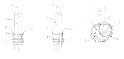
- FIG. 1 shows a sealing sleeve 1 on a line 2, wherein the inner diameter of the sealing sleeve 1 substantially corresponds to the outer diameter of the conduit 2.
- the sealing sleeve 1 is a rotating part made of brass, which has a substantially cylindrical inner contour, with a groove 5 for receiving a retaining clip.
- the sealing sleeve 1 is located on the inside of a phase 3 on the inside. is If the sealing sleeve 1 on the line 2, so Lot 4 can be introduced into the phase 3, so that the sealing sleeve 1 and the line 2 are sealed together.
- FIG. 2 shows a sealing sleeve 1 according to the invention on a line 2. It differs in the form of the prior art essentially in that the inner contour of the sealing sleeve 1 via a cannula-shaped gap 7 which extends axially from an axial end 8 in the sealing sleeve 1 and inside ends, features. From the same axial end 8, the diameter of the sealing sleeve 1 narrows slightly by means of a conical surface 6 in the direction of the sealing sleeve interior in order to extend in a further region with a constant, narrowed diameter.
- the cone here has an angle smaller than 2 °.
- the sealing sleeve 1 can be made of plastic.
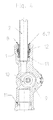
- FIG. 4 shows a line 2 with inventive sealing sleeve 1 in a connector 9 with impeller sensor 10.
- a sealing O-ring 13 is pushed on the side facing away from the cannula-shaped gap 7 side. Subsequently, the line 2 is inserted into the connection piece 9, so that the O-ring 13 seals the line 2 to the connection piece 9.
- Through 2 holes 11 in the connector 9 (seen in the lower part of the connector 9, in which there is no line) a retaining clip 12 is inserted, which engages in the groove 5 and secures the line 2 against axial displacement.
Landscapes
- Engineering & Computer Science (AREA)
- General Engineering & Computer Science (AREA)
- Mechanical Engineering (AREA)
- Physics & Mathematics (AREA)
- Thermal Sciences (AREA)
- Chemical & Material Sciences (AREA)
- Combustion & Propulsion (AREA)
- Non-Disconnectible Joints And Screw-Threaded Joints (AREA)
- Joints With Sleeves (AREA)
- Quick-Acting Or Multi-Walled Pipe Joints (AREA)
Abstract
Description
- Die Erfindung betrifft eine Dichtmuffe, insbesondere für Heizungen.
- Bei Heizgeräten müssen wasserführende Teile wasserdicht miteinander verbunden werden. Die Verbindung soll in vielen Fällen wieder lösbar sein, um einen Ausbau von Bauteilen zu ermöglichen. Hierzu werden häufig Dichtmuffen verwendet. Diese werden häufig aus Messing hergestellt und mit Lot mit Rohren verlötet. Auch kann eine Dichtmuffe auf ein Rohr aufgeschoben werden und das Rohr dann hydraulisch aufgeweitet werden, so dass die Teile miteinander verpresst werden. Auch kann ein Anlötnippel mittels eines Lötrings verbunden werden.
- Der Erfindung liegt die Aufgabe zugrunde, eine einfachere Verbindung zu ermöglichen.
- Dies wird gemäß den Merkmalen des Anspruchs 1 dadurch gelöst, dass die Dichtmuffe eine im Wesentlichen zylindrische Innenkontur besitzt, wobei die Innenkontur über einen kanülenförmigen Spalt, der sich von einem axialen Ende axial in die Dichtmuffe erstreckt und im Inneren endet, verfügt. Durch diesen Spalt kann Klebstoff eingebracht werden, um die Dichtmuffe mit einer Leitung zu verbinden.
- Vorteilhafte Ausgestaltungen ergeben sich aus den Merkmalen der abhängigen Ansprüche.
- Verengt sich die Dichtmuffe in einem Bereich vom Ende des Spaltes, an welchem dieser beginnt bis zum Muffeninneren leicht kegelig oder konisch und erstreckt sich in einem weiteren Bereich mit konstantem, verengtem Durchmesser, so kann die Leitung einfacher eingeführt werden und der Klebstoff wird durch die Kapillarwirkung in die Verbindung gezogen.
- Die Dichtmuffe kann aus Kunststoff hergestellt werden, da durch die Klebung auf Löten verzichtet werden kann und somit das Temperaturniveau beim Fügen geringere Materialanforderungen stellt.
- Die Erfindung wird nun anhand der Figuren detailliert erläutert. Hierbei zeigen:
- Figur 1:
- Eine Dichtmuffe gemäß dem Stand der Technik auf einer Leitung
- Figur 2:
- Eine erfindungsgemäße Dichtmuffe auf einer Leitung
- Figur 3:
- Die erfindungsgemäße Dichtmuffe
- Figur 4:
- Eine Steckverbindung mit einer erfindungsgemäßen Dichtmuffe
-
Figur 1 zeigt eine Dichtmuffe 1 auf einer Leitung 2, wobei der Innendurchmesser der Dichtmuffe 1 im Wesentlichen dem Außendurchmesser der Leitung 2 entspricht. Bei der Dichtmuffe 1 handelt es sich um ein Drehteil aus Messing, das im Wesentlichen eine zylindrische Innenkontur besitzt, mit einer Nut 5 zur Aufnahme einer Halteklammer. An einem axialen Ende 8 der Dichtmuffe 1 befindet sich an der Innenseite eine Phase 3 auf der Innenseite. Befindet sich die Dichtmuffe 1 über der Leitung 2, so kann Lot 4 in die Phase 3 eingebracht werden, so dass werden die Dichtmuffe 1 und die Leitung 2 dicht miteinander verbunden sind. -
Figur 2 zeigt eine erfindungsgemäße Dichtmuffe 1 auf einer Leitung 2. Sie unterscheidet sich in der Form vom Stand der Technik im Wesentlichen dadurch, dass die Innenkontur der Dichtmuffe 1 über einen kanülenförmigen Spalt 7, der sich von einem axialen Ende 8 axial in die Dichtmuffe 1 erstreckt und im Inneren endet, verfügt. Vom selben axialen Ende 8 verengt sich der Durchmesser der Dichtmuffe 1 leicht mittels einer Kegelfläche 6 in Richtung des Dichtmuffeninneren, um sich in einem weiteren Bereich mit konstantem, verengtem Durchmesser zu erstrecken. Der Kegel weist hierbei einen Winkel kleiner 2° auf. - Zur Verbindung wird zunächst die Dichtmuffe 1 über die Leitung 2 geschoben. Anschließend wird Klebstoff in den kanülenförmigen Spalt 7 eingeführt, der sich durch die Kapillarwirkung sowohl in den kanülenförmigen Spalt 7, als auch in den kegelförmigen Raum zwischen Kegelfläche 6 der Dichtmuffe 1 und Leitung 2 zieht. Hierdurch erfolgt eine Verklebung über den gesamten radialen Umfang.
- Da das Verkleben bei deutlich niedrigeren Temperaturen stattfindet als Löten, kann die Dichtmuffe 1 aus Kunststoff hergestellt sein.
-
Figur 4 zeigt eine Leitung 2 mit erfindungsgemäßer Dichtmuffe 1 in einem Anschlussstück 9 mit Flügelradsensor 10. Über die Leitung 2 wird auf der dem kanülenförmigen Spalt 7 abgewandten Seite ein dichtender O-Ring 13 geschoben. Anschließend wird die Leitung 2 in das Anschlussstück 9 eingeführt, so dass der O-Ring 13 die Leitung 2 zum Anschlussstück 9 abdichtet. Durch 2 Bohrungen 11 im Anschlussstück 9 (zu sehen im unteren Teil des Anschlussstücks 9, in dem sich keine Leitung befindet) wird eine Halteklammer 12 eingeschoben, welche in die Nut 5 eingreift und die Leitung 2 gegen axiale Verschiebung sichert. -
- 1
- Dichtmuffe
- 2
- Leitung
- 3
- Phase
- 4
- Lot
- 5
- Nut
- 6
- Kegelfläche
- 7
- kanülenförmiger Spalt
- 8
- axiales Ende
- 9
- Anschlussstück
- 10
- Flügelradsensor
- 11
- Bohrung
- 12
- Halteklammer
- 13
- O-Ring
Claims (3)
- Dichtmuffe (1) zum dichten Verbinden von hydraulischen oder pneumatischen Leitungen (2), wobei die Dichtmuffe eine im Wesentlichen zylindrische Innenkontur besitzt, dadurch gekennzeichnet, dass die Innenkontur über einen kanülenförmigen Spalt, der sich von einem axialen Ende axial in die Dichtmuffe erstreckt und im Inneren endet, verfügt.
- Dichtmuffe nach Anspruch 1, dadurch gekennzeichnet, dass die Dichtmuffe sich in einem Bereich vom Ende des Spaltes an welchem dieser beginnt bis zum Muffeninneren leicht konisch oder kegelförmig verengt und in einem weiteren Bereich mit konstantem, verengtem Durchmesser erstreckt.
- Dichtmuffe nach einem der vorhergehenden Ansprüche, dadurch gekennzeichnet, dass die Dichtmuffe aus Kunststoff hergestellt ist.
Applications Claiming Priority (1)
| Application Number | Priority Date | Filing Date | Title |
|---|---|---|---|
| DE102014207537.8A DE102014207537A1 (de) | 2014-04-22 | 2014-04-22 | Dichtmuffe |
Publications (2)
| Publication Number | Publication Date |
|---|---|
| EP2937615A1 true EP2937615A1 (de) | 2015-10-28 |
| EP2937615B1 EP2937615B1 (de) | 2017-09-27 |
Family
ID=52997320
Family Applications (1)
| Application Number | Title | Priority Date | Filing Date |
|---|---|---|---|
| EP15164386.3A Not-in-force EP2937615B1 (de) | 2014-04-22 | 2015-04-21 | Dichtmuffe |
Country Status (2)
| Country | Link |
|---|---|
| EP (1) | EP2937615B1 (de) |
| DE (1) | DE102014207537A1 (de) |
Citations (5)
| Publication number | Priority date | Publication date | Assignee | Title |
|---|---|---|---|---|
| DE1229351B (de) * | 1957-09-30 | 1966-11-24 | Amercoat Corp | Rohrverbindung |
| AU521637B2 (en) * | 1978-04-19 | 1982-04-22 | Zap-Lok Systems International Inc. | Pipe joint |
| DE29609748U1 (de) * | 1996-06-04 | 1997-01-02 | Karl Pittl, Metallwerk, Ges.m.b.H. & Co. KG, Fulpmes | Lösbare Steckverbindung an Rohrleitung |
| US20020014771A1 (en) * | 2000-05-18 | 2002-02-07 | Yuuichi Gotoh | Pipe connector, pipe-connecting structure, and connecting method |
| FR2891889A1 (fr) * | 2005-10-07 | 2007-04-13 | Caillau Ets | Embout de connexion etanche et piece terminale pour un tel embout |
Family Cites Families (6)
| Publication number | Priority date | Publication date | Assignee | Title |
|---|---|---|---|---|
| US3567257A (en) * | 1968-10-11 | 1971-03-02 | Connecticut Research & Mfg Cor | Tapered pipe joint |
| US3937641A (en) * | 1974-08-30 | 1976-02-10 | General Electric Company | Method of assembling adhesive joint |
| US4196923A (en) * | 1977-11-25 | 1980-04-08 | Carrier Corporation | Adhesive bonding of aluminum coils |
| US4330924A (en) * | 1980-01-31 | 1982-05-25 | General Electric Company | Method of forming crimped tube joint |
| DE8504719U1 (de) * | 1985-02-20 | 1985-07-25 | Blomberg-Werke Kg, 4730 Ahlen | Rohrverbindung |
| DE102004055889A1 (de) * | 2003-11-21 | 2005-06-09 | Linde Ag | Verbindung und Verfahren zur Herstellung einer Verbindung zwischen einem zylindrischen, keramischen und einem metallischen Bauteil |
-
2014
- 2014-04-22 DE DE102014207537.8A patent/DE102014207537A1/de not_active Withdrawn
-
2015
- 2015-04-21 EP EP15164386.3A patent/EP2937615B1/de not_active Not-in-force
Patent Citations (5)
| Publication number | Priority date | Publication date | Assignee | Title |
|---|---|---|---|---|
| DE1229351B (de) * | 1957-09-30 | 1966-11-24 | Amercoat Corp | Rohrverbindung |
| AU521637B2 (en) * | 1978-04-19 | 1982-04-22 | Zap-Lok Systems International Inc. | Pipe joint |
| DE29609748U1 (de) * | 1996-06-04 | 1997-01-02 | Karl Pittl, Metallwerk, Ges.m.b.H. & Co. KG, Fulpmes | Lösbare Steckverbindung an Rohrleitung |
| US20020014771A1 (en) * | 2000-05-18 | 2002-02-07 | Yuuichi Gotoh | Pipe connector, pipe-connecting structure, and connecting method |
| FR2891889A1 (fr) * | 2005-10-07 | 2007-04-13 | Caillau Ets | Embout de connexion etanche et piece terminale pour un tel embout |
Also Published As
| Publication number | Publication date |
|---|---|
| DE102014207537A1 (de) | 2015-10-22 |
| EP2937615B1 (de) | 2017-09-27 |
Similar Documents
| Publication | Publication Date | Title |
|---|---|---|
| EP2527704B1 (de) | Verbinder für eine Fluidleitung und Fluidleitung | |
| DE19609257C2 (de) | Rohrverbindung | |
| DE4304680C1 (de) | Abdichtende Verbindung von Kunststoff-Metall-Kunststoff-Verbundrohren | |
| DE102015204689A1 (de) | Rohrverbindungssystem | |
| DE202017106289U1 (de) | Rohrverbinder | |
| DE102012010647A1 (de) | Anschlussfitting | |
| EP2937615B1 (de) | Dichtmuffe | |
| EP1431645B1 (de) | Rohrverschraubung | |
| EP3115671A1 (de) | Transition fitting | |
| WO2010028872A1 (de) | Nicht lösbare rohrleitungsverbindung | |
| DE202004002219U1 (de) | Anschlußelement für Sonnenkollektoren | |
| DE102009020942A1 (de) | Rohrverbindungssystem | |
| DE102010023424A1 (de) | Drehbare Verbindung für Fluid führende Leitungen insbesondere für Wasser- und Gasleitungen | |
| DE3013312C2 (de) | ||
| DE503083C (de) | Rohrverbindung | |
| DE102017126239A1 (de) | Verschluss für ein Kunststoffrohr | |
| CH246764A (de) | Kupplung an Leitungen aus duktilem Material. | |
| DE2227857A1 (de) | Gewindedichtung | |
| DE202014105784U1 (de) | Vorrichtung zur Gasbeflutung | |
| DE2426730C3 (de) | Rohrschelle für den Anschluß von Rohrstutzen an Rohrleitungen | |
| DE102013225765B4 (de) | Schnell lösbares druckdichtes Verbindungssystem und Verfahren zum Herstellen einer lösbaren druckdichten Verbindung zwischen Rohrleitungen | |
| DE102015118850A1 (de) | Rohrsteckverbindung | |
| EP2642173A1 (de) | Anschlussvorrichtung für einen ringgewellten Schlauch | |
| DE1892010U (de) | Oelschlauch aus kunststoff. | |
| DE10260576A1 (de) | Rohrverschraubung |
Legal Events
| Date | Code | Title | Description |
|---|---|---|---|
| PUAI | Public reference made under article 153(3) epc to a published international application that has entered the european phase |
Free format text: ORIGINAL CODE: 0009012 |
|
| AK | Designated contracting states |
Kind code of ref document: A1 Designated state(s): AL AT BE BG CH CY CZ DE DK EE ES FI FR GB GR HR HU IE IS IT LI LT LU LV MC MK MT NL NO PL PT RO RS SE SI SK SM TR |
|
| AX | Request for extension of the european patent |
Extension state: BA ME |
|
| 17P | Request for examination filed |
Effective date: 20160426 |
|
| RBV | Designated contracting states (corrected) |
Designated state(s): AL AT BE BG CH CY CZ DE DK EE ES FI FR GB GR HR HU IE IS IT LI LT LU LV MC MK MT NL NO PL PT RO RS SE SI SK SM TR |
|
| 17Q | First examination report despatched |
Effective date: 20160907 |
|
| GRAP | Despatch of communication of intention to grant a patent |
Free format text: ORIGINAL CODE: EPIDOSNIGR1 |
|
| RIC1 | Information provided on ipc code assigned before grant |
Ipc: F24D 3/12 20060101ALI20170510BHEP Ipc: F16L 37/14 20060101AFI20170510BHEP Ipc: F16L 13/10 20060101ALN20170510BHEP Ipc: F24D 19/00 20060101ALI20170510BHEP |
|
| INTG | Intention to grant announced |
Effective date: 20170531 |
|
| GRAS | Grant fee paid |
Free format text: ORIGINAL CODE: EPIDOSNIGR3 |
|
| GRAA | (expected) grant |
Free format text: ORIGINAL CODE: 0009210 |
|
| AK | Designated contracting states |
Kind code of ref document: B1 Designated state(s): AL AT BE BG CH CY CZ DE DK EE ES FI FR GB GR HR HU IE IS IT LI LT LU LV MC MK MT NL NO PL PT RO RS SE SI SK SM TR |
|
| REG | Reference to a national code |
Ref country code: GB Ref legal event code: FG4D Free format text: NOT ENGLISH |
|
| REG | Reference to a national code |
Ref country code: CH Ref legal event code: EP |
|
| REG | Reference to a national code |
Ref country code: AT Ref legal event code: REF Ref document number: 932282 Country of ref document: AT Kind code of ref document: T Effective date: 20171015 |
|
| REG | Reference to a national code |
Ref country code: IE Ref legal event code: FG4D Free format text: LANGUAGE OF EP DOCUMENT: GERMAN |
|
| REG | Reference to a national code |
Ref country code: DE Ref legal event code: R096 Ref document number: 502015001967 Country of ref document: DE |
|
| REG | Reference to a national code |
Ref country code: NL Ref legal event code: FP |
|
| PG25 | Lapsed in a contracting state [announced via postgrant information from national office to epo] |
Ref country code: SE Free format text: LAPSE BECAUSE OF FAILURE TO SUBMIT A TRANSLATION OF THE DESCRIPTION OR TO PAY THE FEE WITHIN THE PRESCRIBED TIME-LIMIT Effective date: 20170927 Ref country code: NO Free format text: LAPSE BECAUSE OF FAILURE TO SUBMIT A TRANSLATION OF THE DESCRIPTION OR TO PAY THE FEE WITHIN THE PRESCRIBED TIME-LIMIT Effective date: 20171227 Ref country code: LT Free format text: LAPSE BECAUSE OF FAILURE TO SUBMIT A TRANSLATION OF THE DESCRIPTION OR TO PAY THE FEE WITHIN THE PRESCRIBED TIME-LIMIT Effective date: 20170927 Ref country code: FI Free format text: LAPSE BECAUSE OF FAILURE TO SUBMIT A TRANSLATION OF THE DESCRIPTION OR TO PAY THE FEE WITHIN THE PRESCRIBED TIME-LIMIT Effective date: 20170927 Ref country code: HR Free format text: LAPSE BECAUSE OF FAILURE TO SUBMIT A TRANSLATION OF THE DESCRIPTION OR TO PAY THE FEE WITHIN THE PRESCRIBED TIME-LIMIT Effective date: 20170927 |
|
| REG | Reference to a national code |
Ref country code: LT Ref legal event code: MG4D |
|
| PG25 | Lapsed in a contracting state [announced via postgrant information from national office to epo] |
Ref country code: LV Free format text: LAPSE BECAUSE OF FAILURE TO SUBMIT A TRANSLATION OF THE DESCRIPTION OR TO PAY THE FEE WITHIN THE PRESCRIBED TIME-LIMIT Effective date: 20170927 Ref country code: GR Free format text: LAPSE BECAUSE OF FAILURE TO SUBMIT A TRANSLATION OF THE DESCRIPTION OR TO PAY THE FEE WITHIN THE PRESCRIBED TIME-LIMIT Effective date: 20171228 Ref country code: RS Free format text: LAPSE BECAUSE OF FAILURE TO SUBMIT A TRANSLATION OF THE DESCRIPTION OR TO PAY THE FEE WITHIN THE PRESCRIBED TIME-LIMIT Effective date: 20170927 Ref country code: BG Free format text: LAPSE BECAUSE OF FAILURE TO SUBMIT A TRANSLATION OF THE DESCRIPTION OR TO PAY THE FEE WITHIN THE PRESCRIBED TIME-LIMIT Effective date: 20171227 |
|
| REG | Reference to a national code |
Ref country code: FR Ref legal event code: PLFP Year of fee payment: 4 |
|
| PG25 | Lapsed in a contracting state [announced via postgrant information from national office to epo] |
Ref country code: RO Free format text: LAPSE BECAUSE OF FAILURE TO SUBMIT A TRANSLATION OF THE DESCRIPTION OR TO PAY THE FEE WITHIN THE PRESCRIBED TIME-LIMIT Effective date: 20170927 Ref country code: ES Free format text: LAPSE BECAUSE OF FAILURE TO SUBMIT A TRANSLATION OF THE DESCRIPTION OR TO PAY THE FEE WITHIN THE PRESCRIBED TIME-LIMIT Effective date: 20170927 Ref country code: CZ Free format text: LAPSE BECAUSE OF FAILURE TO SUBMIT A TRANSLATION OF THE DESCRIPTION OR TO PAY THE FEE WITHIN THE PRESCRIBED TIME-LIMIT Effective date: 20170927 |
|
| PG25 | Lapsed in a contracting state [announced via postgrant information from national office to epo] |
Ref country code: SK Free format text: LAPSE BECAUSE OF FAILURE TO SUBMIT A TRANSLATION OF THE DESCRIPTION OR TO PAY THE FEE WITHIN THE PRESCRIBED TIME-LIMIT Effective date: 20170927 Ref country code: IS Free format text: LAPSE BECAUSE OF FAILURE TO SUBMIT A TRANSLATION OF THE DESCRIPTION OR TO PAY THE FEE WITHIN THE PRESCRIBED TIME-LIMIT Effective date: 20180127 Ref country code: IT Free format text: LAPSE BECAUSE OF FAILURE TO SUBMIT A TRANSLATION OF THE DESCRIPTION OR TO PAY THE FEE WITHIN THE PRESCRIBED TIME-LIMIT Effective date: 20170927 Ref country code: SM Free format text: LAPSE BECAUSE OF FAILURE TO SUBMIT A TRANSLATION OF THE DESCRIPTION OR TO PAY THE FEE WITHIN THE PRESCRIBED TIME-LIMIT Effective date: 20170927 Ref country code: EE Free format text: LAPSE BECAUSE OF FAILURE TO SUBMIT A TRANSLATION OF THE DESCRIPTION OR TO PAY THE FEE WITHIN THE PRESCRIBED TIME-LIMIT Effective date: 20170927 |
|
| REG | Reference to a national code |
Ref country code: DE Ref legal event code: R097 Ref document number: 502015001967 Country of ref document: DE |
|
| PG25 | Lapsed in a contracting state [announced via postgrant information from national office to epo] |
Ref country code: DK Free format text: LAPSE BECAUSE OF FAILURE TO SUBMIT A TRANSLATION OF THE DESCRIPTION OR TO PAY THE FEE WITHIN THE PRESCRIBED TIME-LIMIT Effective date: 20170927 |
|
| PLBE | No opposition filed within time limit |
Free format text: ORIGINAL CODE: 0009261 |
|
| STAA | Information on the status of an ep patent application or granted ep patent |
Free format text: STATUS: NO OPPOSITION FILED WITHIN TIME LIMIT |
|
| PG25 | Lapsed in a contracting state [announced via postgrant information from national office to epo] |
Ref country code: PL Free format text: LAPSE BECAUSE OF FAILURE TO SUBMIT A TRANSLATION OF THE DESCRIPTION OR TO PAY THE FEE WITHIN THE PRESCRIBED TIME-LIMIT Effective date: 20170927 |
|
| 26N | No opposition filed |
Effective date: 20180628 |
|
| PG25 | Lapsed in a contracting state [announced via postgrant information from national office to epo] |
Ref country code: MT Free format text: LAPSE BECAUSE OF FAILURE TO SUBMIT A TRANSLATION OF THE DESCRIPTION OR TO PAY THE FEE WITHIN THE PRESCRIBED TIME-LIMIT Effective date: 20170927 |
|
| PG25 | Lapsed in a contracting state [announced via postgrant information from national office to epo] |
Ref country code: MC Free format text: LAPSE BECAUSE OF FAILURE TO SUBMIT A TRANSLATION OF THE DESCRIPTION OR TO PAY THE FEE WITHIN THE PRESCRIBED TIME-LIMIT Effective date: 20170927 Ref country code: SI Free format text: LAPSE BECAUSE OF FAILURE TO SUBMIT A TRANSLATION OF THE DESCRIPTION OR TO PAY THE FEE WITHIN THE PRESCRIBED TIME-LIMIT Effective date: 20170927 |
|
| REG | Reference to a national code |
Ref country code: CH Ref legal event code: PL |
|
| REG | Reference to a national code |
Ref country code: BE Ref legal event code: MM Effective date: 20180430 |
|
| REG | Reference to a national code |
Ref country code: IE Ref legal event code: MM4A |
|
| PG25 | Lapsed in a contracting state [announced via postgrant information from national office to epo] |
Ref country code: LU Free format text: LAPSE BECAUSE OF NON-PAYMENT OF DUE FEES Effective date: 20180421 |
|
| PG25 | Lapsed in a contracting state [announced via postgrant information from national office to epo] |
Ref country code: LI Free format text: LAPSE BECAUSE OF NON-PAYMENT OF DUE FEES Effective date: 20180430 Ref country code: CH Free format text: LAPSE BECAUSE OF NON-PAYMENT OF DUE FEES Effective date: 20180430 Ref country code: BE Free format text: LAPSE BECAUSE OF NON-PAYMENT OF DUE FEES Effective date: 20180430 |
|
| PG25 | Lapsed in a contracting state [announced via postgrant information from national office to epo] |
Ref country code: IE Free format text: LAPSE BECAUSE OF NON-PAYMENT OF DUE FEES Effective date: 20180421 |
|
| PG25 | Lapsed in a contracting state [announced via postgrant information from national office to epo] |
Ref country code: TR Free format text: LAPSE BECAUSE OF FAILURE TO SUBMIT A TRANSLATION OF THE DESCRIPTION OR TO PAY THE FEE WITHIN THE PRESCRIBED TIME-LIMIT Effective date: 20170927 |
|
| PG25 | Lapsed in a contracting state [announced via postgrant information from national office to epo] |
Ref country code: PT Free format text: LAPSE BECAUSE OF FAILURE TO SUBMIT A TRANSLATION OF THE DESCRIPTION OR TO PAY THE FEE WITHIN THE PRESCRIBED TIME-LIMIT Effective date: 20170927 |
|
| PG25 | Lapsed in a contracting state [announced via postgrant information from national office to epo] |
Ref country code: HU Free format text: LAPSE BECAUSE OF FAILURE TO SUBMIT A TRANSLATION OF THE DESCRIPTION OR TO PAY THE FEE WITHIN THE PRESCRIBED TIME-LIMIT; INVALID AB INITIO Effective date: 20150421 Ref country code: CY Free format text: LAPSE BECAUSE OF FAILURE TO SUBMIT A TRANSLATION OF THE DESCRIPTION OR TO PAY THE FEE WITHIN THE PRESCRIBED TIME-LIMIT Effective date: 20170927 Ref country code: MK Free format text: LAPSE BECAUSE OF NON-PAYMENT OF DUE FEES Effective date: 20170927 |
|
| PG25 | Lapsed in a contracting state [announced via postgrant information from national office to epo] |
Ref country code: AL Free format text: LAPSE BECAUSE OF FAILURE TO SUBMIT A TRANSLATION OF THE DESCRIPTION OR TO PAY THE FEE WITHIN THE PRESCRIBED TIME-LIMIT Effective date: 20170927 |
|
| PGFP | Annual fee paid to national office [announced via postgrant information from national office to epo] |
Ref country code: GB Payment date: 20230330 Year of fee payment: 9 |
|
| PGFP | Annual fee paid to national office [announced via postgrant information from national office to epo] |
Ref country code: NL Payment date: 20240325 Year of fee payment: 10 |
|
| PGFP | Annual fee paid to national office [announced via postgrant information from national office to epo] |
Ref country code: DE Payment date: 20240325 Year of fee payment: 10 |
|
| PGFP | Annual fee paid to national office [announced via postgrant information from national office to epo] |
Ref country code: AT Payment date: 20240403 Year of fee payment: 10 |
|
| PGFP | Annual fee paid to national office [announced via postgrant information from national office to epo] |
Ref country code: FR Payment date: 20240423 Year of fee payment: 10 |
|
| GBPC | Gb: european patent ceased through non-payment of renewal fee |
Effective date: 20240421 |
|
| PG25 | Lapsed in a contracting state [announced via postgrant information from national office to epo] |
Ref country code: GB Free format text: LAPSE BECAUSE OF NON-PAYMENT OF DUE FEES Effective date: 20240421 |
|
| PG25 | Lapsed in a contracting state [announced via postgrant information from national office to epo] |
Ref country code: GB Free format text: LAPSE BECAUSE OF NON-PAYMENT OF DUE FEES Effective date: 20240421 |
|
| REG | Reference to a national code |
Ref country code: DE Ref legal event code: R119 Ref document number: 502015001967 Country of ref document: DE |
|
| REG | Reference to a national code |
Ref country code: NL Ref legal event code: MM Effective date: 20250501 |
|
| REG | Reference to a national code |
Ref country code: AT Ref legal event code: MM01 Ref document number: 932282 Country of ref document: AT Kind code of ref document: T Effective date: 20250421 |
|
| PG25 | Lapsed in a contracting state [announced via postgrant information from national office to epo] |
Ref country code: DE Free format text: LAPSE BECAUSE OF NON-PAYMENT OF DUE FEES Effective date: 20251104 |
|
| PG25 | Lapsed in a contracting state [announced via postgrant information from national office to epo] |
Ref country code: AT Free format text: LAPSE BECAUSE OF NON-PAYMENT OF DUE FEES Effective date: 20250421 |
|
| PG25 | Lapsed in a contracting state [announced via postgrant information from national office to epo] |
Ref country code: NL Free format text: LAPSE BECAUSE OF NON-PAYMENT OF DUE FEES Effective date: 20250501 Ref country code: FR Free format text: LAPSE BECAUSE OF NON-PAYMENT OF DUE FEES Effective date: 20250430 |