EP2937583A1 - Wälzlager - Google Patents
Wälzlager Download PDFInfo
- Publication number
- EP2937583A1 EP2937583A1 EP15165056.1A EP15165056A EP2937583A1 EP 2937583 A1 EP2937583 A1 EP 2937583A1 EP 15165056 A EP15165056 A EP 15165056A EP 2937583 A1 EP2937583 A1 EP 2937583A1
- Authority
- EP
- European Patent Office
- Prior art keywords
- rolling
- cage
- web
- distance
- bearing according
- Prior art date
- Legal status (The legal status is an assumption and is not a legal conclusion. Google has not performed a legal analysis and makes no representation as to the accuracy of the status listed.)
- Granted
Links
Images



Classifications
-
- F—MECHANICAL ENGINEERING; LIGHTING; HEATING; WEAPONS; BLASTING
- F16—ENGINEERING ELEMENTS AND UNITS; GENERAL MEASURES FOR PRODUCING AND MAINTAINING EFFECTIVE FUNCTIONING OF MACHINES OR INSTALLATIONS; THERMAL INSULATION IN GENERAL
- F16C—SHAFTS; FLEXIBLE SHAFTS; ELEMENTS OR CRANKSHAFT MECHANISMS; ROTARY BODIES OTHER THAN GEARING ELEMENTS; BEARINGS
- F16C33/00—Parts of bearings; Special methods for making bearings or parts thereof
- F16C33/30—Parts of ball or roller bearings
- F16C33/46—Cages for rollers or needles
- F16C33/50—Cages for rollers or needles formed of interconnected members, e.g. chains
- F16C33/506—Cages for rollers or needles formed of interconnected members, e.g. chains formed as a flexible belt
-
- F—MECHANICAL ENGINEERING; LIGHTING; HEATING; WEAPONS; BLASTING
- F16—ENGINEERING ELEMENTS AND UNITS; GENERAL MEASURES FOR PRODUCING AND MAINTAINING EFFECTIVE FUNCTIONING OF MACHINES OR INSTALLATIONS; THERMAL INSULATION IN GENERAL
- F16C—SHAFTS; FLEXIBLE SHAFTS; ELEMENTS OR CRANKSHAFT MECHANISMS; ROTARY BODIES OTHER THAN GEARING ELEMENTS; BEARINGS
- F16C33/00—Parts of bearings; Special methods for making bearings or parts thereof
- F16C33/30—Parts of ball or roller bearings
- F16C33/46—Cages for rollers or needles
- F16C33/4617—Massive or moulded cages having cage pockets surrounding the rollers, e.g. machined window cages
- F16C33/4664—Massive or moulded cages having cage pockets surrounding the rollers, e.g. machined window cages with more than three parts, e.g. two end rings connected by individual stays
-
- F—MECHANICAL ENGINEERING; LIGHTING; HEATING; WEAPONS; BLASTING
- F16—ENGINEERING ELEMENTS AND UNITS; GENERAL MEASURES FOR PRODUCING AND MAINTAINING EFFECTIVE FUNCTIONING OF MACHINES OR INSTALLATIONS; THERMAL INSULATION IN GENERAL
- F16C—SHAFTS; FLEXIBLE SHAFTS; ELEMENTS OR CRANKSHAFT MECHANISMS; ROTARY BODIES OTHER THAN GEARING ELEMENTS; BEARINGS
- F16C33/00—Parts of bearings; Special methods for making bearings or parts thereof
- F16C33/30—Parts of ball or roller bearings
- F16C33/46—Cages for rollers or needles
- F16C33/467—Details of individual pockets, e.g. shape or roller retaining means
- F16C33/4676—Details of individual pockets, e.g. shape or roller retaining means of the stays separating adjacent cage pockets, e.g. guide means for the bearing-surface of the rollers
-
- F—MECHANICAL ENGINEERING; LIGHTING; HEATING; WEAPONS; BLASTING
- F16—ENGINEERING ELEMENTS AND UNITS; GENERAL MEASURES FOR PRODUCING AND MAINTAINING EFFECTIVE FUNCTIONING OF MACHINES OR INSTALLATIONS; THERMAL INSULATION IN GENERAL
- F16C—SHAFTS; FLEXIBLE SHAFTS; ELEMENTS OR CRANKSHAFT MECHANISMS; ROTARY BODIES OTHER THAN GEARING ELEMENTS; BEARINGS
- F16C33/00—Parts of bearings; Special methods for making bearings or parts thereof
- F16C33/30—Parts of ball or roller bearings
- F16C33/46—Cages for rollers or needles
- F16C33/467—Details of individual pockets, e.g. shape or roller retaining means
- F16C33/4682—Details of individual pockets, e.g. shape or roller retaining means of the end walls, e.g. interaction with the end faces of the rollers
-
- F—MECHANICAL ENGINEERING; LIGHTING; HEATING; WEAPONS; BLASTING
- F16—ENGINEERING ELEMENTS AND UNITS; GENERAL MEASURES FOR PRODUCING AND MAINTAINING EFFECTIVE FUNCTIONING OF MACHINES OR INSTALLATIONS; THERMAL INSULATION IN GENERAL
- F16C—SHAFTS; FLEXIBLE SHAFTS; ELEMENTS OR CRANKSHAFT MECHANISMS; ROTARY BODIES OTHER THAN GEARING ELEMENTS; BEARINGS
- F16C33/00—Parts of bearings; Special methods for making bearings or parts thereof
- F16C33/02—Parts of sliding-contact bearings
- F16C33/04—Brasses; Bushes; Linings
- F16C33/046—Brasses; Bushes; Linings divided or split, e.g. half-bearings or rolled sleeves
Definitions
- the invention relates to a rolling bearing having at least one inner ring and at least one outer ring and at least one row of rolling elements, which are arranged between the bearing rings and with their axes on a pitch circle, wherein the rolling elements are held by a cage, which consists of a number of cage segments, wherein each cage segment has at least one receiving pocket for a rolling element.
- Segmented cages of the type mentioned have proved their worth because of their mobility, especially in large-scale warehouses.
- Such a solution shows, for example, the WO 2012/076583 A2 .
- the maximum number of rollers that can be placed between the bearing rings is limited by the thickness of the connecting webs between side plates of the cage segments. These take namely on the pitch circle of the camp to a certain extent extent to claim, so that there is no room for a rolling element.
- the invention has for its object to provide a rolling bearing of the type mentioned so with a segment cage that a very stable construction of the cage is ensured. At the same time it should be possible to place as many rolling elements between the bearing rings.
- each cage segment comprises two axially spaced side plates, between which extend at least two webs in the axial direction, which are connected to the side plates, wherein a first web radially below the pitch circle and a radial beam passing through the axis of the rolling element circumferentially offset (eg, to the left), and wherein a second land above the pitch circle is arranged so as to be diametrically opposed to the first land with respect to the axis of the rolling element (ie Example case shifted to the right).
- the webs preferably extend, as seen in the axial direction, out of the region of the side plates in the circumferential direction and toward the adjacent cage segment.
- the webs are preferably provided on their side facing in the receiving pocket rolling elements with a contact surface. They may be provided on their side facing away from the roller located in the receiving pocket side with an outer surface. In this case, it is preferably provided that the distance between the outer surface of the web and the circumferentially adjacent rolling elements is greater than the distance between the contact surface of the web and located in the receiving pocket rolling elements.
- a uniform arrangement of the cage segments over the circumference of the measured radially distance between the radially inner end of the cage segment and an inner ring raceway or a guide board is preferably greater than the distance measured in the radial direction between the contact surface of the radially inner web and in the Receiving pocket rolling elements. Further, it is preferably provided that with a uniform arrangement of the cage segments over the circumference of the radially measured distance between the radially outer end of the cage segment and an outer ring race or a guide board is greater than the distance measured in the radial direction between the contact surface of the radially outer web and the rolling element located in the receiving pocket.
- the radially outer end of the cage segment can be formed by at least one knob-shaped projection, which is arranged on the cage segment, in particular integrally formed.
- the webs preferably have at their radially outer and radially inner ends in respective axial sections on a clear width, which is smaller than the diameter of the rolling element. This creates a snap action into the cage segment for the rolling element.
- two circumferentially successive cage segments have an at least partially complementary, non-planar shape.
- the cage segments are preferably made of plastic, in particular of fiber-reinforced plastic.
- plastic in particular of fiber-reinforced plastic.
- metallic materials are also possible in general.
- the rolling bearing is preferably a tapered roller bearing, a spherical roller bearing or a cylindrical roller bearing.
- the cage is usually segmented such that per cage segment, a rolling element is guided. But it is also just possible that a cage segment has more than one receiving pocket, so that a plurality of rolling elements are guided with a segment. In this case, the described embodiment applies to the effect that several such multi-roll segments adjoin one another in the circumferential direction. The solution described then also describes the transitions between adjacent segments.
- the cage is according to the above explanations thus first of two side surfaces (side plates), which are arranged on the two end faces of the rolling elements (ie the rollers).
- the side surfaces are connected to the two mentioned webs. These webs are once below the pitch circle diameter of the rollers and once above the same and each stand out of the direct line of sight between the side surfaces out in the space bounded by the side surfaces of the adjacent cage segment.
- the individual cage segments are dimensioned such that in no operating state there is contact with a web with a web, a roller or a side surface of an adjacent cage segment.
- Each web comes into contact with the roller inside the cage segment via a cam surface, but not with another roller.
- the smallest distance between a web and a roll of the adjacent cage is always greater than zero.
- the side surfaces of the cage segment are arranged radially beyond the region of the two raceways. They are designed so that with a uniform alignment of the radially outermost points to the inner or outer diameter of the cage segments to the bearing axis toward the distance to the outermost or innermost contact area is always greater than the game of role within the cage segment (measured in the radial direction ).
- the outermost points of the cage segments may optionally be designed as rounded projections (knob-like projections).
- all roles are surrounded by a cage segment.
- the cages each touch their circumferentially located side portions.
- the cage set as a whole has a circumferential clearance that compensates for the different thermal expansions of cage segments and bearing rings.
- the webs have a Schmiegungs simulation to the inner role. These can be made with a diameter or have another suitable shape.
- the Schmiegungs vom can also be designed so that they fulfill a snap function by which the roller is held in the cage segment, namely, when the clearances to the radially outer and inner ends of the webs are smaller than the roll diameter.
- the snap action can also be realized by locally plastically deformed areas of a non-plastic cage.
- the cage webs of a cage segment penetrate with a suitably shaped (non-planar) transition in the adjacent cage segment, so that there is a complementary hollow cylindrical shape between two adjacent cage segments.
- the side plates may optionally have recesses at their radially inner and / or radially outer region. In the following embodiment, this is shown for the radially inner region of the cage webs.
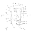
- a rolling bearing 1 and details thereof can be seen, wherein the rolling bearing is designed as a cylindrical roller bearing. It has an inner ring 2 and an outer ring 3, wherein between the rings 2, 3 rolling elements 4 are arranged.
- the axes M the rolling elements 4 lie on a pitch circle 5; the rolling elements 4 have a diameter D w .
- the rolling elements 4 are held by a cage 6 in the desired position, wherein the cage 6 consists of individual cage segments 6 ', 6 ", 6", which are arranged consecutively in the circumferential direction U, s. For this Fig. 3 where three cage segments are shown. Each cage segment 6 ', 6 ", 6'” has a receiving pocket 7 for a rolling element 4.
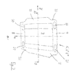
- Each cage segment 6 ', 6 ", 6'” has two side plates 8, s. this too Fig. 7 from which this is best shown, wherein the side plates 8 are connected to each other via two webs 10 and 11.
- the two side plates 8, 9 are spaced from each other in the axial direction a; the distance is held by the two webs 10 and 11.
- the one (first) web 10 below the pitch circle 5 and to a radial beam 12, which extends through the axis M of the rolling element 4, is arranged offset in the circumferential direction U (in Fig. 2 This can be clearly seen where the web 10 is offset from the radial beam 12 to the left).
- the other (second) land 11 above the pitch circle 5 is arranged so as to be diametrically opposed to the first land 10 with respect to the axis M of the rolling body 4 (in FIG Fig. 2 is good to see that the web 11 is offset from the radial beam 12 to the right).
- the web 10 has a contact surface 13 for the rolling elements 4 and the web 11 corresponding to a contact surface 14 for the rolling elements 4.
- a contact surface 13 for the rolling elements 4 At the other, from the rolling elements 4 facing side of the web 10 has an outer surface 15 and the web 11 a Outer surface 16.
- the shape of the contact surfaces 13, 14 will usually be circular arc, but this is not mandatory; an analogous configuration can also be provided for the outer surfaces 15 and 16.
- the cage segment 6 ', 6 ", 6'” is further provided on its radially outer surface with projections 20 and 21; whose location can be in Fig. 7 be seen.
- the projections 20, 21 are designed knob-like.
- Fig. 7 can still be seen that the cage segment 6 ', 6 ", 6'” provided in its lying in the circumferential direction U end portions with a non-planar shape 22; this formation 22 is designed so that two cage segment 6 ', 6 ", 6'” which collide in the circumferential direction U, here complement one another in a complementary manner and thus form a substantially hollow-cylindrical cage structure.
- Distances c 1 , c 2 , c 3 and c 4 can be defined in the radial direction r.
- the distance c 1 is the distance of the radially inward end of the cage segment 6 ', 6 ", 6'” from the guide board 18.
- the distance c 2 is the distance of the radially outer end of the cage segment 6 ', 6 ", 6'” from the outer raceway 19 (taking into account the projections 20 and 21).
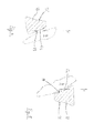
- the distance c 3 (s. Fig. 4 ) is the radial distance of the contact surface 13 from the rolling element 4; the distance c 4 (s. Fig. 5 ) is the radial distance of the contact surface 14 from the rolling element. 4
- the distance c 1 is greater than the distance c. 3
- a uniform arrangement of the cage segments 6 ', 6 ", 6'" about the circumference U of the distance c 2 is larger than the distance c. 4
- the side plates 8, 9 here have recesses 23 in the radially inner region between their two end regions lying in the circumferential direction. These recesses 23 provided here in the radially inward region can alternatively or additionally also be provided in the radially outer region.
Landscapes
- Engineering & Computer Science (AREA)
- General Engineering & Computer Science (AREA)
- Mechanical Engineering (AREA)
- Rolling Contact Bearings (AREA)
Abstract
Description
- Die Erfindung betrifft ein Wälzlager mit mindestens einem Innenring und mindestens einem Außenring sowie mindestens einer Reihe Wälzkörper, die zwischen den Lagerringen und mit ihren Achsen auf einem Teilkreis angeordnet sind, wobei die Wälzkörper von einem Käfig gehalten werden, der aus einer Anzahl Käfigsegmenten besteht, wobei jedes Käfigsegment mindestens eine Aufnahmetasche für einen Wälzkörper aufweist.
- Insbesondere bei Großlagern haben sich segmentierte Käfige der genannten Art wegen ihrer Beweglichkeit bewährt. Eine solche Lösung zeigt beispielsweise die
WO 2012/076583 A2 . Die maximale Anzahl an Rollen, die zwischen den Lagerringen platziert werden kann, wird dabei durch die Dicke der Verbindungsstege zwischen seitlichen Platten der Käfigsegmente begrenzt. Diese nehmen nämlich am Teilkreis des Lagers eine gewisse Umfangserstreckung in Anspruch, so dass insofern kein Platz für einen Wälzkörper vorliegt. - Bekannt ist auch eine Lösung, bei der der Käfig aus Eintaschensegmenten besteht, wobei ein solches Segment nur bei jedem zweiten Wälzkörper vorgesehen ist. Hierdurch kann zwar Raum für Wälzkörper gewonnen werden, allerdings auf Kosten der Stabilität der Führung der Wälzkörper.
- Der Erfindung liegt die Aufgabe zugrunde, ein Wälzlager der eingangs genannten Art so mit einem Segmentkäfig zu versehen, dass eine sehr stabile Bauweise des Käfigs sichergestellt wird. Gleichzeitig soll es ermöglicht werden, möglichst viele Wälzkörper zwischen den Lagerringen zu platzieren.
- Die Lösung dieser Aufgabe durch die Erfindung ist dadurch gekennzeichnet, dass jedes Käfigsegment zwei axial beabstandete Seitenplatten umfasst, zwischen denen sich mindestens zwei Stege in axiale Richtung erstrecken, die mit den Seitenplatten verbunden sind, wobei ein erster Steg radial unterhalb des Teilkreises und zu einem Radialstrahl, der durch die Achse des Wälzkörpers verläuft, in Umfangsrichtung versetzt (z. B. nach links) angeordnet ist und wobei ein zweiter Steg oberhalb des Teilkreises so angeordnet ist, dass er zum ersten Steg bezüglich der Achse des Wälzkörpers diametral angeordnet ist (also im Beispielsfall nach rechts versetzt).
- Die Stege erstrecken sich dabei vorzugsweise, gesehen in axiale Richtung, aus dem Bereich der Seitenplatten in Umfangsrichtung heraus und hin zum benachbarten Käfigsegment.
- Die Stege sind bevorzugt an ihrer dem sich in der Aufnahmetasche befindlichen Wälzkörper zugewandten Seite mit einer Anlauffläche versehen. Sie können an ihrer von dem sich in der Aufnahmetasche befindlichen Wälzkörper abgewandten Seite mit einer Außenfläche versehen sein. In diesem Falle ist bevorzugt vorgesehen, dass der Abstand zwischen der Außenfläche des Stegs und dem in Umfangsrichtung benachbarten Wälzkörper größer ist als der Abstand zwischen der Anlauffläche des Stegs und dem sich in der Aufnahmetasche befindlichen Wälzkörper.
- Bei gleichmäßiger Anordnung der Käfigsegmente über den Umfang ist dabei der in radiale Richtung gemessene Abstand zwischen dem radial innenliegenden Ende des Käfigsegments und einer Innenringlaufbahn oder einem Führungsbord vorzugsweise größer als der in radiale Richtung gemessene Abstand zwischen der Anlauffläche des radial innenliegenden Stegs und dem sich in der Aufnahmetasche befindlichen Wälzkörper. Ferner ist bevorzugt vorgesehen, dass bei gleichmäßiger Anordnung der Käfigsegmente über den Umfang der in radiale Richtung gemessene Abstand zwischen dem radial außenliegenden Ende des Käfigsegments und einer Außenringlaufbahn oder einem Führungsbord größer ist als der in radiale Richtung gemessene Abstand zwischen der Anlauffläche des radial außenliegenden Stegs und dem sich in der Aufnahmetasche befindlichen Wälzkörper.
- Das radial außenliegende Ende des Käfigsegments kann durch mindestens einen noppen-förmigen Vorsprung gebildet werden, der am Käfigsegment angeordnet, insbesondere angeformt, ist.
- Die Stege weisen bevorzugt an ihren radial außenliegenden und radial innenliegenden Enden in jeweiligen Axialschnitten eine lichte Weite auf, die kleiner ist als der Durchmesser des Wälzkörpers. Hiermit wird für den Wälzkörper eine Einschnappfunktion in das Käfigsegment geschaffen.
- Bevorzugt weisen zwei in Umfangsrichtung aufeinander folgende Käfigsegmente eine zueinander zumindest abschnittsweise komplementäre, nichtebene Ausformung auf.
- Die Käfigsegmente bestehen bevorzugt aus Kunststoff, insbesondere aus faserverstärktem Kunststoff. Allerdings sind generell natürlich auch metallische Werkstoffe möglich.
- Das Wälzlager ist bevorzugt ein Kegelrollenlager, ein Pendelrollenlager oder ein Zylinderrollenlager.
- Der Käfig ist dabei zumeist dergestalt segmentiert, dass pro Käfigsegment ein Wälzkörper geführt wird. Es ist aber auch genauso möglich, dass ein Käfigsegment mehr als eine Aufnahmetasche aufweist, so dass mit einem Segment mehrere Wälzkörper geführt werden. In diesem Falle gilt die erläuterte Ausgestaltung dahingehend, dass sich mehrere solcher Mehrrollensegmente in Umfangsrichtung aneinander anschließen. Die beschriebene Lösung beschreibt dann auch die Übergänge zwischen benachbarten Segmenten.
- Der Käfig besteht gemäß obigen Erläuterungen also zunächst aus zwei Seitenflächen (Seitenplatten), die an den beiden Stirnseiten der Wälzkörper (d. h. der Rollen) angeordnet sind. Die Seitenflächen sind mit den beiden genannten Stegen verbunden. Diese Stege sind einmal unterhalb des Teilkreisdurchmessers der Rollen und einmal oberhalb desselben angeordnet und stehen jeweils aus der direkten Sichtlinie zwischen den Seitenflächen heraus in den durch die Seitenflächen begrenzten Raum des benachbarten Käfigsegments. Die einzelnen Käfigsegmente sind dabei so dimensioniert, dass es in keinem Betriebszustand zu einer Berührung eines Steges mit einem Steg, einer Rolle oder einer Seitenfläche eines benachbarten Käfigsegments kommt.
- Jeder Steg kommt über eine Schmiegungsfläche mit der innerhalb des Käfigsegments befindlichen Rolle in Berührung, nicht aber mit einer anderen Rolle. Der kleinste Abstand zwischen einem Steg und einer Rolle des benachbarten Käfigs ist immer größer als Null.
- Die Seitenflächen des Käfigsegments sind radial jenseits des Bereiches der beiden Laufbahnen angeordnet. Sie sind so gestaltet, dass bei einer gleichmäßigen Ausrichtung der radial äußersten Stellen zum Innen- bzw. Außendurchmesser der Käfigsegmente zur Lagerachse hin der Abstand zum äußersten bzw. innersten Kontaktbereich immer größer ist, als das Spiel der Rolle innerhalb des Käfigsegments (gemessen in radiale Richtung). Die äußersten Stellen der Käfigsegmente können gegebenenfalls als ausgerundete Erhebungen ausgeführt sein (noppenartige Vorsprünge).
- Bevorzugt sind alle Rollen von einem Käfigsegment umgeben. Die Käfige berühren sich jeweils mit ihren in Umfangsrichtung gelegenen Seitenbereichen. Der Käfigsatz hat in seiner Gesamtheit ein Umfangsspiel, das die unterschiedlichen thermischen Dehnungen von Käfigsegmenten und Lagerringen ausgleicht.
- Die Stege haben eine Schmiegungsfläche zur innen liegenden Rolle hin. Diese können mit einem Durchmesser ausgeführt sein oder eine andere passende Gestalt haben.
- Die Schmiegungsflächen können dabei auch so ausgeführt sein, dass sie eine Schnappfunktion erfüllen, durch welche die Rolle im Käfigsegment gehalten wird, wenn nämlich die lichten Abstände an den radial außenliegenden und innenliegenden Ende der Stege kleiner sind als der Rollendurchmesser. Alternativ kann die Schnappfunktion auch durch lokal plastisch verformte Bereiche eines Nicht-Kunststoffkäfigs realisiert werden.
- Die Käfigstege eines Käfigsegments dringen mit einem geeignet gestalteten (nicht-ebenen) Übergang in das Nachbar-Käfigsegment ein, so dass sich zwischen zwei benachbarten Käfigsegmenten eine komplementäre hohlzylindrische Form ergibt.
- Die Seitenplatten können optional an ihrem radial inneren und/oder radial äußeren Bereich Ausnehmungen aufweisen. Im nachfolgenden Ausführungsbeispiel ist dies für den radial innenliegenden Bereich der Käfigstege dargestellt.
- Mit der vorgeschlagenen Lösung wird also ein Konzept vorgeschlagen, mit dem die Stege dergestalt in radialer Richtung übereinander angeordnet sind, dass in Umfangsrichtung Platz für Wälzkörper gewonnen wird. Demgemäß können mehr Wälzkörper in das Lager eingebaut werden, so dass sich die Tragfähigkeit des Lagers erhöht.
- Somit wird vorteilhaft dank einer ausreichend großen Breite der Stege in Umgangsrichtung dennoch eine hohe Stabilität des Käfigs gewährleistet; gleichzeitig können mehr Rollen im Lager angeordnet werden, als dies bei vorbekannten Lösungen der Fall ist.
- In der Zeichnung ist ein Ausführungsbeispiel der Erfindung dargestellt. Es zeigen:
- Fig. 1
- einen Ausschnitt aus einem Wälzlager, und zwar einem Zylinderrollenlager, wobei ein Käfigsegment zu sehen ist, das einen Wälzkörper führt,
- Fig. 2
- in der Darstellung nach
Fig. 1 den Ausschnitt aus dem Wälzlager, wobei jetzt ein Axialschnitt (Schnitt A-B gemäßFig. 7 ) dargestellt ist, - Fig. 3
- einen Ausschnitt aus dem Wälzlager nach
Fig. 1 bzw.Fig. 2 in einem Axialschnitt, wobei hier drei in Umfangsrichtung aufeinander folgende Käfigsegmente zu sehen sind, - Fig. 4
- die Einzelheit "X" gemäß
Fig. 3 , - Fig. 5
- die Einzelheit "Y" gemäß
Fig. 3 , - Fig. 6
- den Axialschnitt eines Wälzkörpers zwischen zwei Stegen eines Käfigsegments und
- Fig. 7
- die Ansicht eines Käfigsegments, gesehen aus radialer Richtung.
- In den Figuren sind ein Wälzlager 1 und Einzelheiten desselben zu sehen, wobei das Wälzlager als Zylinderrollenlager ausgeführt ist. Es weist einen Innenring 2 und einen Außenring 3 auf, wobei zwischen den Ringen 2, 3 Wälzkörper 4 angeordnet sind. Die Achsen M der Wälzkörper 4 liegen auf einem Teilkreis 5; die Wälzkörper 4 weisen einen Durchmesser Dw auf.
- Die Wälzkörper 4 werden durch einen Käfig 6 in der gewünschten Position gehalten, wobei der Käfig 6 aus einzelnen Käfigsegmenten 6`, 6", 6" besteht, die in Umfangsrichtung U aufeinander folgend angeordnet sind, s. hierzu
Fig. 3 , wo drei Käfigsegmente dargestellt sind. Jedes Käfigsegment 6', 6", 6'" hat eine Aufnahmetasche 7 für einen Wälzkörper 4. - Jedes Käfigsegment 6', 6", 6'" weist zwei Seitenplatten 8 auf, s. hierzu auch
Fig. 7 , aus der dies am besten hervorgeht, wobei die Seitenplatten 8 jeweils über zwei Stege 10 und 11 miteinander verbunden sind. Die beiden Seitenplatten 8, 9 sind in axialer Richtung a voneinander beabstandet; der Abstand wird durch die beiden Stege 10 und 11 gehalten. - Wesentlich ist, dass der eine (erste) Steg 10 unterhalb des Teilkreises 5 und zu einem Radialstrahl 12, der durch die Achse M des Wälzkörpers 4 verläuft, in Umfangsrichtung U versetzt angeordnet ist (in
Fig. 2 ist dies gut zu erkennen, wo der Steg 10 vom Radialstrahl 12 aus gesehen nach links versetzt ist). Indes ist der andere (zweite) Steg 11 oberhalb des Teilkreises 5 so angeordnet ist, dass er zum ersten Steg 10 bezüglich der Achse M des Wälzkörpers 4 diametral angeordnet ist (inFig. 2 ist gut zu sehen, dass der Steg 11 vom Radialstrahl 12 aus gesehen nach rechts versetzt ist). - Während in den
Figuren 1 und2 noch die Innenringlaufbahn 17 und die Außenunglaufbahn 19 skizziert ist, ist ein Führungsbord 18 bzw. dessen radial nach außen weisende Führungsfläche nur inFig. 3 angedeutet. - Wie aus der Zusammenschau der Figuren - insbesondere aus den
Figuren 4 und 5 - weiter hervorgeht, hat der Steg 10 eine Anlauffläche 13 für den Wälzkörper 4 und der Steg 11 entsprechend eine Anlauffläche 14 für den Wälzkörper 4. An der anderen, vom Wälzkörper 4 ab gewandten Seite hat der Steg 10 eine Außenfläche 15 und der Steg 11 eine Außenfläche 16. Die Ausformung der Anlaufflächen 13, 14 wird in der Regel kreisbogenförmig erfolgen, dies ist allerdings nicht zwingend; eine analoge Ausgestaltung kann auch für die Außenflächen 15 und 16 vorgesehen werden. - Das Käfigsegment 6', 6", 6'" ist weiterhin an seiner radial außenliegenden Fläche mit Vorsprüngen 20 und 21 versehen; deren Lage kann in
Fig. 7 gesehen werden. Die Vorsprünge 20, 21 sind noppenartig ausgestaltet. - In
Fig. 7 ist noch zu erkennen, dass das Käfigsegment 6', 6", 6'" in seinen in Umfangsrichtung U liegenden Endbereichen mit einer nicht-ebenen Ausformung 22 versehen; diese Ausformung 22 ist so gestaltet, dass zwei in Umfangsrichtung U zusammenstoßende Käfigsegment 6', 6", 6'" hier komplementär zueinander passen und so eine im wesentlichen hohlzylindrische Käfigstruktur bilden. - Zu der Wahl der geometrischen Größen ist folgendes zu sagen:
- Wie aus
Fig. 3 hervorgeht, lässt sich ein Abstand s1 definieren, der den Abstand der Außenfläche 15 des Stegs 10 zum benachbarten Wälzkörper 4 markiert; entsprechend ergibt sich der Abstand s2 als Distanz zwischen der Außenfläche 16 des Stegs 11 zum benachbarten Wälzkörper 4. Ein Abstand s3 liegt zwischen der Anlauffläche 13 des Stegs 10 und dem geführten Wälzkörper 4 vor, ein Abstand s4 zwischen der Anlauffläche 14 des Stegs 11 und dem geführten Wälzkörper 4. - Für die Größe des Gesamtspiels, d. h. das Spiel in Umfangsrichtung und aufsummiert über alle Abstände s1, s2, s3 bzw. s4 erfolgt nach fachmännischen Gesichtspunkten, so dass eine hinreichende Führung der Wälzkörper gegeben, indes kein Verklemmen der Wälzkörper zu befürchten ist.
- Es gilt, dass der Abstand s1 bzw. s2 zwischen den Außenflächen 15, 16 und dem in Umfangsrichtung U benachbarten Wälzkörper 4 größer ist als der Abstand s3 bzw. s4 zwischen der Anlauffläche 13, 14 und dem sich in der Aufnahmetasche 7 befindlichen Wälzkörper 4. So wird ein unerwünschter Kontakt des benachbarten Käfigsegments mit dem geführten Wälzkörper verhindert.
- In der Zusammenschau der
Figuren 3 ,4 und 5 ergibt sich weiter folgendes: In radiale Richtung r gemessen lassen sich Abstände c1, c2, c3 und c4 definieren: Der Abstand c1 ist der Abstand des radial innenliegenden Endes des Käfigsegments 6', 6", 6'" vom Führungsbord 18. Der Abstand c2 ist der Abstand des radial außenliegenden Endes des Käfigsegments 6', 6", 6'" von der Außeminglaufbahn 19 (unter Berücksichtigung der Vorsprünge 20 und 21). Der Abstand c3 (s.Fig. 4 ) ist der radiale Abstand der Anlauffläche 13 vom Wälzkörper 4; der Abstand c4 (s.Fig. 5 ) ist der radiale Abstand der Anlauffläche 14 vom Wälzkörper 4. - Es gilt hier, dass bei gleichmäßiger Anordnung der Käfigsegmente 6', 6", 6'" über den Umfang U der Abstand c1 größer ist als der Abstand c3. Ferner ist bei gleichmäßiger Anordnung der Käfigsegmente 6', 6", 6'" über den Umfang U der Abstand c2 größer als der Abstand c4.
- Aus
Fig. 6 geht noch eine weitere bevorzugte Ausgestaltung hervor: Um eine Einschnappfunktion für die Wälzkörper 4 in die Aufnahmetasche 7 zu schaffen, ist vorgesehen, dass die Stege 10, 11 an ihren radial außenliegenden und radial innenliegenden Enden in jeweiligen Axialschnitten eine lichte Weite D2 bzw. D3 aufweisen, die kleiner ist als der Durchmesser Dw des Wälzkörpers 4. - In den
Figuren 1 bis 3 ist noch eine weitere Fortbildung zu sehen: Die Seitenplatten 8, 9 weisen hier im radial innenliegenden Bereich zwischen ihren beiden in Umfangsrichtung liegenden Endbereichen Ausnehmungen 23 auf. Diese hier in radial innenliegenden Bereich vorgesehenen Ausnehmungen 23 können alternativ oder additiv auch im radial außenliegenden Bereich vorgesehen werden. -
- 1
- Wälzlager
- 2
- Innenring
- 3
- Außenring
- 4
- Wälzkörper
- 5
- Teilkreis
- 6
- Käfig
- 6', 6'', 6'''
- Käfigsegment
- 7
- Aufnahmetasche
- 8
- Seitenplatte
- 9
- Seitenplatte
- 10
- Steg
- 11
- Steg
- 12
- Radialstrahl
- 13
- Anlauffläche
- 14
- Anlauffläche
- 15
- Außenfläche
- 16
- Außenfläche
- 17
- Innenringlaufbahn
- 18
- Führungsbord
- 19
- Außenringlaufbahn
- 20
- Vorsprung
- 21
- Vorsprung
- 22
- Ausformung
- 23
- Ausnehmung
- M
- Achse des Wälzkörpers
- a
- axiale Richtung
- r
- radiale Richtung
- U
- Umfangsrichtung
- Dw
- Durchmesser des Wälzkörpers
- D2
- lichte Weite
- D3
- lichte Weite
- s1
- Abstand
- s2
- Abstand
- s3
- Abstand
- s4
- Abstand
- c1
- Abstand
- c2
- Abstand
- c3
- Abstand
- c4
- Abstand
Claims (12)
- Wälzlager (1) mit mindestens einem Innenring (2) und mindestens einem Außenring (3) sowie mindestens einer Reihe Wälzkörper (4), die zwischen den Lagerringen (2, 3) und mit ihren Achsen (M) auf einem Teilkreis (5) angeordnet sind, wobei die Wälzkörper (4) von einem Käfig (6) gehalten werden, der aus einer Anzahl Käfigsegmenten (6', 6", 6'") besteht, wobei jedes Käfigsegment (6', 6", 6"') mindestens eine Aufnahmetasche (7) für einen Wälzkörper (4) aufweist,
dadurch gekennzeichnet, dass
jedes Käfigsegment (6', 6`, 6") zwei axial (a) beabstandete Seitenplatten (8, 9) umfasst, zwischen denen sich mindestens zwei Stege (10, 11) in axiale Richtung (a) erstrecken, die mit den Seitenplatten (8, 9) verbunden sind, wobei ein erster Steg (10) unterhalb des Teilkreises (5) und zu einem Radialstrahl (12), der durch die Achse (M) des Wälzkörpers (4) verläuft, in Umfangsrichtung (U) versetzt angeordnet ist und wobei ein zweiter Steg (11) oberhalb des Teilkreises (5) so angeordnet ist, dass er zum ersten Steg (10) bezüglich der Achse (M) des Wälzkörpers (4) diametral angeordnet ist. - Wälzlager nach Anspruch 1, dadurch gekennzeichnet, dass sich die Stege (10, 11), gesehen in axiale Richtung (a), aus dem Bereich der Seitenplatten (8, 9) in Umfangsrichtung (U) heraus erstrecken.
- Wälzlager nach Anspruch 1 oder 2, dadurch gekennzeichnet, dass die Stege (10, 11) an ihrer dem sich in der Aufnahmetasche (7) befindlichen Wälzkörper (4) zugewandten Seite mit einer Anlauffläche (13, 14) versehen sind.
- Wälzlager nach einem der Ansprüche 1 bis 3, dadurch gekennzeichnet, dass die Stege (10, 11) an ihrer von dem sich in der Aufnahmetasche (7) befindlichen Wälzkörper (4) ab gewandten Seite mit einer Außenfläche (15, 16) versehen sind.
- Wälzlager nach Anspruch 3 und 4, dadurch gekennzeichnet, dass der Abstand (s1, s2) zwischen der Außenfläche (15, 16) des Stegs (10, 11) und dem in Umfangsrichtung (U) benachbarten Wälzkörper (4) größer ist als der Abstand (s3, s4) zwischen der Anlauffläche (13, 14) des Stegs (10, 11) und dem sich in der Aufnahmetasche (7) befindlichen Wälzkörper (4).
- Wälzlager nach einem der Ansprüche 1 bis 5, dadurch gekennzeichnet, dass bei gleichmäßiger Anordnung der Käfigsegmente (6', 6", 6'") über den Umfang (U) der in radiale Richtung (r) gemessene Abstand (c1) zwischen dem radial innenliegenden Ende des Käfigsegments (6', 6", 6"') und einer Inneminglaufbahn (17) oder einem Führungsbord (18) größer ist als der in radiale Richtung (r) gemessene Abstand (c3) zwischen der Anlauffläche (13) des radial innenliegenden Stegs (10) und dem sich in der Aufnahmetasche (7) befindlichen Wälzkörper (4).
- Wälzlager nach einem der Ansprüche 1 bis 6, dadurch gekennzeichnet, dass bei gleichmäßiger Anordnung der Käfigsegmente (6', 6", 6"') über den Umfang (U) der in radiale Richtung (r) gemessene Abstand (c2) zwischen dem radial außenliegenden Ende des Käfigsegments (6', 6", 6'") und einer Außenringlaufbahn (19) oder einem Führungsbord größer ist als der in radiale Richtung (r) gemessene Abstand (c4) zwischen der Anlauffläche (14) des radial außenliegenden Stegs (11) und dem sich in der Aufnahmetasche (7) befindlichen Wälzkörper (4).
- Wälzlager nach einem der Ansprüche 1 bis 7, dadurch gekennzeichnet, dass das radial außenliegende Ende des Käfigsegments (6', 6", 6'") durch mindestens einen noppenförmigen Vorsprung (20, 21) gebildet wird, der am Käfigsegment (6', 6", 6"') angeordnet, insbesondere angeformt, ist.
- Wälzlager nach einem der Ansprüche 1 bis 8, dadurch gekennzeichnet, dass die Stege (10, 11) an ihren radial außenliegenden und radial innenliegenden Enden in jeweiligen Axialschnitten eine lichte Weite (D2, D3) aufweisen, die kleiner ist als der Durchmesser (Dw) des Wälzkörpers (4).
- Wälzlager nach einem der Ansprüche 1 bis 9, dadurch gekennzeichnet, dass zwei in Umfangsrichtung (U) aufeinander folgende Käfigsegmente (6', 6", 6"') eine zueinander zumindest abschnittsweise komplementäre, nichtebene Ausformung (22) aufweisen.
- Wälzlager nach einem der Ansprüche 1 bis 10, dadurch gekennzeichnet, dass die Käfigsegmente (6', 6", 6"') aus Kunststoff bestehen, insbesondere aus faserverstärktem Kunststoff.
- Wälzlager nach einem der Ansprüche 1 bis 11, dadurch gekennzeichnet, dass es ein Kegelrollenlager, ein Pendelrollenlager oder ein Zylinderrollenlager ist.
Applications Claiming Priority (1)
| Application Number | Priority Date | Filing Date | Title |
|---|---|---|---|
| DE102014207831.8A DE102014207831A1 (de) | 2014-04-25 | 2014-04-25 | Wälzlager |
Publications (2)
| Publication Number | Publication Date |
|---|---|
| EP2937583A1 true EP2937583A1 (de) | 2015-10-28 |
| EP2937583B1 EP2937583B1 (de) | 2018-12-26 |
Family
ID=52997993
Family Applications (1)
| Application Number | Title | Priority Date | Filing Date |
|---|---|---|---|
| EP15165056.1A Active EP2937583B1 (de) | 2014-04-25 | 2015-04-24 | Wälzlager |
Country Status (4)
| Country | Link |
|---|---|
| EP (1) | EP2937583B1 (de) |
| DE (1) | DE102014207831A1 (de) |
| DK (1) | DK2937583T3 (de) |
| ES (1) | ES2716403T3 (de) |
Citations (2)
| Publication number | Priority date | Publication date | Assignee | Title |
|---|---|---|---|---|
| DE102009017598A1 (de) * | 2009-04-16 | 2010-10-07 | Aktiebolaget Skf | Käfig für ein Wälzlager und Wälzlager |
| WO2012076583A2 (de) | 2010-12-07 | 2012-06-14 | Aktiebolaget Skf | Käfigsegment eines kegelrollenlagers und kegelrollenlager |
Family Cites Families (8)
| Publication number | Priority date | Publication date | Assignee | Title |
|---|---|---|---|---|
| DE874683C (de) * | 1945-02-03 | 1953-04-27 | Ver Kugellagerfabriken Ag | Kaefig fuer Ringlager |
| FR1559419A (de) * | 1967-04-28 | 1969-03-07 | ||
| FR2222898A5 (de) * | 1973-03-20 | 1974-10-18 | Rks | |
| DE3245332C2 (de) * | 1982-12-08 | 1985-06-27 | FAG Kugelfischer Georg Schäfer KGaA, 8720 Schweinfurt | Segmentkäfig für Rollenlager |
| DE3627153C1 (en) * | 1986-08-11 | 1987-12-10 | Georg Dipl-Ing Gugel | Cage element for cross roller bearings |
| US8764304B2 (en) * | 2006-09-08 | 2014-07-01 | Ntn Corporation | Roller bearing, retainer segment of roller bearing for supporting main shaft of wind-power generator, and main shaft support structure of wind-power generator |
| DE102007009811A1 (de) * | 2007-02-28 | 2008-09-04 | Schaeffler Kg | Mehrteiliger Axialkäfig für ein Großwälzlager |
| DE102009012241A1 (de) * | 2009-03-07 | 2010-09-09 | Werner Beuerlein | Wälzlager mit segmentiertem Käfig |
-
2014
- 2014-04-25 DE DE102014207831.8A patent/DE102014207831A1/de not_active Ceased
-
2015
- 2015-04-24 DK DK15165056.1T patent/DK2937583T3/en active
- 2015-04-24 EP EP15165056.1A patent/EP2937583B1/de active Active
- 2015-04-24 ES ES15165056T patent/ES2716403T3/es active Active
Patent Citations (2)
| Publication number | Priority date | Publication date | Assignee | Title |
|---|---|---|---|---|
| DE102009017598A1 (de) * | 2009-04-16 | 2010-10-07 | Aktiebolaget Skf | Käfig für ein Wälzlager und Wälzlager |
| WO2012076583A2 (de) | 2010-12-07 | 2012-06-14 | Aktiebolaget Skf | Käfigsegment eines kegelrollenlagers und kegelrollenlager |
Also Published As
| Publication number | Publication date |
|---|---|
| DK2937583T3 (en) | 2019-04-08 |
| ES2716403T3 (es) | 2019-06-12 |
| EP2937583B1 (de) | 2018-12-26 |
| DE102014207831A1 (de) | 2015-10-29 |
Similar Documents
| Publication | Publication Date | Title |
|---|---|---|
| EP2129925B1 (de) | Mehrteiliger axialkäfig für ein grosswälzlager | |
| EP2932117B1 (de) | Wälzlager | |
| DE10010295A1 (de) | Radial-Axial-Wälzlager | |
| DE2906210C2 (de) | Zweireihiges Radialpendelrollenlager | |
| DE102013016949A1 (de) | Rollenlager für mindestens zwei Reihen von Rollelementen, insbesondere für den Tunnelbau | |
| EP3129668A1 (de) | Segmentlageranordnung mit formschlüssig gesichertem kunststoffkäfig | |
| WO2018086650A1 (de) | Wälzlagerkäfig mit haltekrallen | |
| DE102016211435A1 (de) | Lagereinheit und Distanzstück | |
| DE102005009980B3 (de) | Wälzlager | |
| DE102009050153A1 (de) | Schrägkugellager, insbesondere Spindellager, mit verbesserter Käfigführung | |
| DE4142433C1 (en) | Combined roller and ball bearing with inner and outer races - is of thin race type with rollers and balls of same dia. and on same race tracks | |
| EP3935287B1 (de) | Käfigsegment eines wälzlagers | |
| DE102009034018A1 (de) | Wälzlager | |
| DE69018586T2 (de) | Wälzlager. | |
| DE102010022964A1 (de) | Segment-Wälzlager mit Synchronisationseinrichtung | |
| WO2007038913A1 (de) | Wälzlager | |
| DE2014420B2 (de) | Kafigring fur Walzlager und Verfahren zu dessen Herstellung | |
| DE102010062479B4 (de) | Wälzlager und Käfig für ein Wälzlager | |
| DE102017110742B4 (de) | Zweireihiges Pendelrollenlager | |
| DE3418621A1 (de) | Waelzlager | |
| EP2937583B1 (de) | Wälzlager | |
| EP2431623A2 (de) | Toroidal-Rollenlager | |
| DE102013218210B3 (de) | Wälzlager | |
| DE102017129773A1 (de) | Pendelrollenlager | |
| EP2325507B1 (de) | Wälzlagerkäfig mit mittig verbreiterten Stegen |
Legal Events
| Date | Code | Title | Description |
|---|---|---|---|
| PUAI | Public reference made under article 153(3) epc to a published international application that has entered the european phase |
Free format text: ORIGINAL CODE: 0009012 |
|
| AK | Designated contracting states |
Kind code of ref document: A1 Designated state(s): AL AT BE BG CH CY CZ DE DK EE ES FI FR GB GR HR HU IE IS IT LI LT LU LV MC MK MT NL NO PL PT RO RS SE SI SK SM TR |
|
| AX | Request for extension of the european patent |
Extension state: BA ME |
|
| 17P | Request for examination filed |
Effective date: 20160428 |
|
| RBV | Designated contracting states (corrected) |
Designated state(s): AL AT BE BG CH CY CZ DE DK EE ES FI FR GB GR HR HU IE IS IT LI LT LU LV MC MK MT NL NO PL PT RO RS SE SI SK SM TR |
|
| STAA | Information on the status of an ep patent application or granted ep patent |
Free format text: STATUS: EXAMINATION IS IN PROGRESS |
|
| 17Q | First examination report despatched |
Effective date: 20171114 |
|
| GRAP | Despatch of communication of intention to grant a patent |
Free format text: ORIGINAL CODE: EPIDOSNIGR1 |
|
| STAA | Information on the status of an ep patent application or granted ep patent |
Free format text: STATUS: GRANT OF PATENT IS INTENDED |
|
| INTG | Intention to grant announced |
Effective date: 20180723 |
|
| GRAS | Grant fee paid |
Free format text: ORIGINAL CODE: EPIDOSNIGR3 |
|
| GRAA | (expected) grant |
Free format text: ORIGINAL CODE: 0009210 |
|
| STAA | Information on the status of an ep patent application or granted ep patent |
Free format text: STATUS: THE PATENT HAS BEEN GRANTED |
|
| AK | Designated contracting states |
Kind code of ref document: B1 Designated state(s): AL AT BE BG CH CY CZ DE DK EE ES FI FR GB GR HR HU IE IS IT LI LT LU LV MC MK MT NL NO PL PT RO RS SE SI SK SM TR |
|
| REG | Reference to a national code |
Ref country code: GB Ref legal event code: FG4D Free format text: NOT ENGLISH |
|
| REG | Reference to a national code |
Ref country code: CH Ref legal event code: EP |
|
| REG | Reference to a national code |
Ref country code: AT Ref legal event code: REF Ref document number: 1081831 Country of ref document: AT Kind code of ref document: T Effective date: 20190115 |
|
| REG | Reference to a national code |
Ref country code: DE Ref legal event code: R096 Ref document number: 502015007380 Country of ref document: DE |
|
| REG | Reference to a national code |
Ref country code: IE Ref legal event code: FG4D Free format text: LANGUAGE OF EP DOCUMENT: GERMAN |
|
| REG | Reference to a national code |
Ref country code: DK Ref legal event code: T3 Effective date: 20190401 |
|
| PG25 | Lapsed in a contracting state [announced via postgrant information from national office to epo] |
Ref country code: LV Free format text: LAPSE BECAUSE OF FAILURE TO SUBMIT A TRANSLATION OF THE DESCRIPTION OR TO PAY THE FEE WITHIN THE PRESCRIBED TIME-LIMIT Effective date: 20181226 Ref country code: HR Free format text: LAPSE BECAUSE OF FAILURE TO SUBMIT A TRANSLATION OF THE DESCRIPTION OR TO PAY THE FEE WITHIN THE PRESCRIBED TIME-LIMIT Effective date: 20181226 Ref country code: BG Free format text: LAPSE BECAUSE OF FAILURE TO SUBMIT A TRANSLATION OF THE DESCRIPTION OR TO PAY THE FEE WITHIN THE PRESCRIBED TIME-LIMIT Effective date: 20190326 Ref country code: NO Free format text: LAPSE BECAUSE OF FAILURE TO SUBMIT A TRANSLATION OF THE DESCRIPTION OR TO PAY THE FEE WITHIN THE PRESCRIBED TIME-LIMIT Effective date: 20190326 Ref country code: LT Free format text: LAPSE BECAUSE OF FAILURE TO SUBMIT A TRANSLATION OF THE DESCRIPTION OR TO PAY THE FEE WITHIN THE PRESCRIBED TIME-LIMIT Effective date: 20181226 Ref country code: FI Free format text: LAPSE BECAUSE OF FAILURE TO SUBMIT A TRANSLATION OF THE DESCRIPTION OR TO PAY THE FEE WITHIN THE PRESCRIBED TIME-LIMIT Effective date: 20181226 |
|
| REG | Reference to a national code |
Ref country code: NL Ref legal event code: MP Effective date: 20181226 |
|
| REG | Reference to a national code |
Ref country code: LT Ref legal event code: MG4D |
|
| PG25 | Lapsed in a contracting state [announced via postgrant information from national office to epo] |
Ref country code: GR Free format text: LAPSE BECAUSE OF FAILURE TO SUBMIT A TRANSLATION OF THE DESCRIPTION OR TO PAY THE FEE WITHIN THE PRESCRIBED TIME-LIMIT Effective date: 20190327 Ref country code: SE Free format text: LAPSE BECAUSE OF FAILURE TO SUBMIT A TRANSLATION OF THE DESCRIPTION OR TO PAY THE FEE WITHIN THE PRESCRIBED TIME-LIMIT Effective date: 20181226 Ref country code: RS Free format text: LAPSE BECAUSE OF FAILURE TO SUBMIT A TRANSLATION OF THE DESCRIPTION OR TO PAY THE FEE WITHIN THE PRESCRIBED TIME-LIMIT Effective date: 20181226 Ref country code: AL Free format text: LAPSE BECAUSE OF FAILURE TO SUBMIT A TRANSLATION OF THE DESCRIPTION OR TO PAY THE FEE WITHIN THE PRESCRIBED TIME-LIMIT Effective date: 20181226 |
|
| REG | Reference to a national code |
Ref country code: ES Ref legal event code: FG2A Ref document number: 2716403 Country of ref document: ES Kind code of ref document: T3 Effective date: 20190612 |
|
| PG25 | Lapsed in a contracting state [announced via postgrant information from national office to epo] |
Ref country code: NL Free format text: LAPSE BECAUSE OF FAILURE TO SUBMIT A TRANSLATION OF THE DESCRIPTION OR TO PAY THE FEE WITHIN THE PRESCRIBED TIME-LIMIT Effective date: 20181226 |
|
| PG25 | Lapsed in a contracting state [announced via postgrant information from national office to epo] |
Ref country code: PL Free format text: LAPSE BECAUSE OF FAILURE TO SUBMIT A TRANSLATION OF THE DESCRIPTION OR TO PAY THE FEE WITHIN THE PRESCRIBED TIME-LIMIT Effective date: 20181226 Ref country code: IT Free format text: LAPSE BECAUSE OF FAILURE TO SUBMIT A TRANSLATION OF THE DESCRIPTION OR TO PAY THE FEE WITHIN THE PRESCRIBED TIME-LIMIT Effective date: 20181226 Ref country code: PT Free format text: LAPSE BECAUSE OF FAILURE TO SUBMIT A TRANSLATION OF THE DESCRIPTION OR TO PAY THE FEE WITHIN THE PRESCRIBED TIME-LIMIT Effective date: 20190426 Ref country code: CZ Free format text: LAPSE BECAUSE OF FAILURE TO SUBMIT A TRANSLATION OF THE DESCRIPTION OR TO PAY THE FEE WITHIN THE PRESCRIBED TIME-LIMIT Effective date: 20181226 |
|
| PG25 | Lapsed in a contracting state [announced via postgrant information from national office to epo] |
Ref country code: RO Free format text: LAPSE BECAUSE OF FAILURE TO SUBMIT A TRANSLATION OF THE DESCRIPTION OR TO PAY THE FEE WITHIN THE PRESCRIBED TIME-LIMIT Effective date: 20181226 Ref country code: IS Free format text: LAPSE BECAUSE OF FAILURE TO SUBMIT A TRANSLATION OF THE DESCRIPTION OR TO PAY THE FEE WITHIN THE PRESCRIBED TIME-LIMIT Effective date: 20190426 Ref country code: SM Free format text: LAPSE BECAUSE OF FAILURE TO SUBMIT A TRANSLATION OF THE DESCRIPTION OR TO PAY THE FEE WITHIN THE PRESCRIBED TIME-LIMIT Effective date: 20181226 Ref country code: EE Free format text: LAPSE BECAUSE OF FAILURE TO SUBMIT A TRANSLATION OF THE DESCRIPTION OR TO PAY THE FEE WITHIN THE PRESCRIBED TIME-LIMIT Effective date: 20181226 Ref country code: SK Free format text: LAPSE BECAUSE OF FAILURE TO SUBMIT A TRANSLATION OF THE DESCRIPTION OR TO PAY THE FEE WITHIN THE PRESCRIBED TIME-LIMIT Effective date: 20181226 |
|
| REG | Reference to a national code |
Ref country code: DE Ref legal event code: R097 Ref document number: 502015007380 Country of ref document: DE |
|
| PLBE | No opposition filed within time limit |
Free format text: ORIGINAL CODE: 0009261 |
|
| STAA | Information on the status of an ep patent application or granted ep patent |
Free format text: STATUS: NO OPPOSITION FILED WITHIN TIME LIMIT |
|
| REG | Reference to a national code |
Ref country code: CH Ref legal event code: PL |
|
| 26N | No opposition filed |
Effective date: 20190927 |
|
| REG | Reference to a national code |
Ref country code: BE Ref legal event code: MM Effective date: 20190430 |
|
| GBPC | Gb: european patent ceased through non-payment of renewal fee |
Effective date: 20190424 |
|
| PG25 | Lapsed in a contracting state [announced via postgrant information from national office to epo] |
Ref country code: LU Free format text: LAPSE BECAUSE OF NON-PAYMENT OF DUE FEES Effective date: 20190424 Ref country code: MC Free format text: LAPSE BECAUSE OF FAILURE TO SUBMIT A TRANSLATION OF THE DESCRIPTION OR TO PAY THE FEE WITHIN THE PRESCRIBED TIME-LIMIT Effective date: 20181226 |
|
| PG25 | Lapsed in a contracting state [announced via postgrant information from national office to epo] |
Ref country code: GB Free format text: LAPSE BECAUSE OF NON-PAYMENT OF DUE FEES Effective date: 20190424 Ref country code: CH Free format text: LAPSE BECAUSE OF NON-PAYMENT OF DUE FEES Effective date: 20190430 Ref country code: LI Free format text: LAPSE BECAUSE OF NON-PAYMENT OF DUE FEES Effective date: 20190430 |
|
| PG25 | Lapsed in a contracting state [announced via postgrant information from national office to epo] |
Ref country code: BE Free format text: LAPSE BECAUSE OF NON-PAYMENT OF DUE FEES Effective date: 20190430 Ref country code: FR Free format text: LAPSE BECAUSE OF NON-PAYMENT OF DUE FEES Effective date: 20190430 Ref country code: SI Free format text: LAPSE BECAUSE OF FAILURE TO SUBMIT A TRANSLATION OF THE DESCRIPTION OR TO PAY THE FEE WITHIN THE PRESCRIBED TIME-LIMIT Effective date: 20181226 |
|
| PG25 | Lapsed in a contracting state [announced via postgrant information from national office to epo] |
Ref country code: TR Free format text: LAPSE BECAUSE OF FAILURE TO SUBMIT A TRANSLATION OF THE DESCRIPTION OR TO PAY THE FEE WITHIN THE PRESCRIBED TIME-LIMIT Effective date: 20181226 |
|
| PG25 | Lapsed in a contracting state [announced via postgrant information from national office to epo] |
Ref country code: IE Free format text: LAPSE BECAUSE OF NON-PAYMENT OF DUE FEES Effective date: 20190424 |
|
| PG25 | Lapsed in a contracting state [announced via postgrant information from national office to epo] |
Ref country code: CY Free format text: LAPSE BECAUSE OF FAILURE TO SUBMIT A TRANSLATION OF THE DESCRIPTION OR TO PAY THE FEE WITHIN THE PRESCRIBED TIME-LIMIT Effective date: 20181226 |
|
| REG | Reference to a national code |
Ref country code: AT Ref legal event code: MM01 Ref document number: 1081831 Country of ref document: AT Kind code of ref document: T Effective date: 20200424 |
|
| PG25 | Lapsed in a contracting state [announced via postgrant information from national office to epo] |
Ref country code: MT Free format text: LAPSE BECAUSE OF FAILURE TO SUBMIT A TRANSLATION OF THE DESCRIPTION OR TO PAY THE FEE WITHIN THE PRESCRIBED TIME-LIMIT Effective date: 20181226 Ref country code: HU Free format text: LAPSE BECAUSE OF FAILURE TO SUBMIT A TRANSLATION OF THE DESCRIPTION OR TO PAY THE FEE WITHIN THE PRESCRIBED TIME-LIMIT; INVALID AB INITIO Effective date: 20150424 |
|
| PG25 | Lapsed in a contracting state [announced via postgrant information from national office to epo] |
Ref country code: AT Free format text: LAPSE BECAUSE OF NON-PAYMENT OF DUE FEES Effective date: 20200424 |
|
| PG25 | Lapsed in a contracting state [announced via postgrant information from national office to epo] |
Ref country code: MK Free format text: LAPSE BECAUSE OF FAILURE TO SUBMIT A TRANSLATION OF THE DESCRIPTION OR TO PAY THE FEE WITHIN THE PRESCRIBED TIME-LIMIT Effective date: 20181226 |
|
| P01 | Opt-out of the competence of the unified patent court (upc) registered |
Effective date: 20230513 |
|
| PGFP | Annual fee paid to national office [announced via postgrant information from national office to epo] |
Ref country code: ES Payment date: 20260507 Year of fee payment: 12 |
|
| PGFP | Annual fee paid to national office [announced via postgrant information from national office to epo] |
Ref country code: DK Payment date: 20260423 Year of fee payment: 12 |
|
| PGFP | Annual fee paid to national office [announced via postgrant information from national office to epo] |
Ref country code: DE Payment date: 20260421 Year of fee payment: 12 |