EP2937243A1 - Verfahren zur leistungsverwaltung in elektrischen anlagen - Google Patents
Verfahren zur leistungsverwaltung in elektrischen anlagen Download PDFInfo
- Publication number
- EP2937243A1 EP2937243A1 EP12826619.4A EP12826619A EP2937243A1 EP 2937243 A1 EP2937243 A1 EP 2937243A1 EP 12826619 A EP12826619 A EP 12826619A EP 2937243 A1 EP2937243 A1 EP 2937243A1
- Authority
- EP
- European Patent Office
- Prior art keywords
- controllable
- electrical installation
- loads
- power
- installation
- Prior art date
- Legal status (The legal status is an assumption and is not a legal conclusion. Google has not performed a legal analysis and makes no representation as to the accuracy of the status listed.)
- Granted
Links
Images


Classifications
-
- H—ELECTRICITY
- H02—GENERATION; CONVERSION OR DISTRIBUTION OF ELECTRIC POWER
- H02J—ELECTRIC POWER NETWORKS; CIRCUIT ARRANGEMENTS OR SYSTEMS FOR SUPPLYING OR DISTRIBUTING ELECTRIC POWER; SYSTEMS FOR STORING ELECTRIC ENERGY
- H02J3/00—Circuit arrangements for AC mains or AC distribution networks
- H02J3/12—Arrangements for adjusting voltage in AC networks by changing a characteristic of the network load
- H02J3/14—Arrangements for adjusting voltage in AC networks by changing a characteristic of the network load by switching loads on to, or off from, the networks, e.g. progressively balanced loading
-
- B—PERFORMING OPERATIONS; TRANSPORTING
- B60—VEHICLES IN GENERAL
- B60L—PROPULSION OF ELECTRICALLY-PROPELLED VEHICLES; SUPPLYING ELECTRIC POWER FOR AUXILIARY EQUIPMENT OF ELECTRICALLY-PROPELLED VEHICLES; ELECTRODYNAMIC BRAKE SYSTEMS FOR VEHICLES IN GENERAL; MAGNETIC SUSPENSION OR LEVITATION FOR VEHICLES; MONITORING OPERATING VARIABLES OF ELECTRICALLY-PROPELLED VEHICLES; ELECTRIC SAFETY DEVICES FOR ELECTRICALLY-PROPELLED VEHICLES
- B60L53/00—Methods of charging batteries, specially adapted for electric vehicles; Charging stations or on-board charging equipment therefor; Exchange of energy storage elements in electric vehicles
- B60L53/60—Monitoring or controlling charging stations
- B60L53/67—Controlling two or more charging stations
-
- H—ELECTRICITY
- H02—GENERATION; CONVERSION OR DISTRIBUTION OF ELECTRIC POWER
- H02J—ELECTRIC POWER NETWORKS; CIRCUIT ARRANGEMENTS OR SYSTEMS FOR SUPPLYING OR DISTRIBUTING ELECTRIC POWER; SYSTEMS FOR STORING ELECTRIC ENERGY
- H02J3/00—Circuit arrangements for AC mains or AC distribution networks
- H02J3/28—Arrangements for balancing of the load in networks by storage of energy
- H02J3/32—Arrangements for balancing of the load in networks by storage of energy using batteries or super capacitors with converting means
- H02J3/322—Arrangements for balancing of the load in networks by storage of energy using batteries or super capacitors with converting means the battery being on-board an electric or hybrid vehicle, e.g. vehicle to grid arrangements [V2G], power aggregation, use of the battery for network load balancing, coordinated or cooperative battery charging
-
- H—ELECTRICITY
- H02—GENERATION; CONVERSION OR DISTRIBUTION OF ELECTRIC POWER
- H02J—ELECTRIC POWER NETWORKS; CIRCUIT ARRANGEMENTS OR SYSTEMS FOR SUPPLYING OR DISTRIBUTING ELECTRIC POWER; SYSTEMS FOR STORING ELECTRIC ENERGY
- H02J3/00—Circuit arrangements for AC mains or AC distribution networks
- H02J3/38—Arrangements for feeding a single network from two or more generators or sources in parallel; Arrangements for feeding already energised networks from additional generators or sources in parallel
- H02J3/381—Dispersed generators
-
- H—ELECTRICITY
- H02—GENERATION; CONVERSION OR DISTRIBUTION OF ELECTRIC POWER
- H02J—ELECTRIC POWER NETWORKS; CIRCUIT ARRANGEMENTS OR SYSTEMS FOR SUPPLYING OR DISTRIBUTING ELECTRIC POWER; SYSTEMS FOR STORING ELECTRIC ENERGY
- H02J2101/00—Supply or distribution of decentralised, dispersed or local electric power generation
- H02J2101/20—Dispersed power generation using renewable energy sources
- H02J2101/22—Solar energy
- H02J2101/24—Photovoltaics
-
- H—ELECTRICITY
- H02—GENERATION; CONVERSION OR DISTRIBUTION OF ELECTRIC POWER
- H02J—ELECTRIC POWER NETWORKS; CIRCUIT ARRANGEMENTS OR SYSTEMS FOR SUPPLYING OR DISTRIBUTING ELECTRIC POWER; SYSTEMS FOR STORING ELECTRIC ENERGY
- H02J2101/00—Supply or distribution of decentralised, dispersed or local electric power generation
- H02J2101/20—Dispersed power generation using renewable energy sources
- H02J2101/28—Wind energy
-
- H—ELECTRICITY
- H02—GENERATION; CONVERSION OR DISTRIBUTION OF ELECTRIC POWER
- H02J—ELECTRIC POWER NETWORKS; CIRCUIT ARRANGEMENTS OR SYSTEMS FOR SUPPLYING OR DISTRIBUTING ELECTRIC POWER; SYSTEMS FOR STORING ELECTRIC ENERGY
- H02J2105/00—Networks for supplying or distributing electric power characterised by their spatial reach or by the load
- H02J2105/30—Networks for supplying or distributing electric power characterised by their spatial reach or by the load the load networks being external to vehicles, i.e. exchanging power with vehicles
- H02J2105/33—Networks for supplying or distributing electric power characterised by their spatial reach or by the load the load networks being external to vehicles, i.e. exchanging power with vehicles exchanging power with road vehicles
- H02J2105/37—Networks for supplying or distributing electric power characterised by their spatial reach or by the load the load networks being external to vehicles, i.e. exchanging power with vehicles exchanging power with road vehicles exchanging power with electric vehicles [EV] or with hybrid electric vehicles [HEV]
-
- H—ELECTRICITY
- H02—GENERATION; CONVERSION OR DISTRIBUTION OF ELECTRIC POWER
- H02J—ELECTRIC POWER NETWORKS; CIRCUIT ARRANGEMENTS OR SYSTEMS FOR SUPPLYING OR DISTRIBUTING ELECTRIC POWER; SYSTEMS FOR STORING ELECTRIC ENERGY
- H02J2105/00—Networks for supplying or distributing electric power characterised by their spatial reach or by the load
- H02J2105/50—Networks for supplying or distributing electric power characterised by their spatial reach or by the load for selectively controlling the operation of the loads
- H02J2105/52—Networks for supplying or distributing electric power characterised by their spatial reach or by the load for selectively controlling the operation of the loads for limitation of the power consumption in the networks or in one section of the networks, e.g. load shedding or peak shaving
-
- Y—GENERAL TAGGING OF NEW TECHNOLOGICAL DEVELOPMENTS; GENERAL TAGGING OF CROSS-SECTIONAL TECHNOLOGIES SPANNING OVER SEVERAL SECTIONS OF THE IPC; TECHNICAL SUBJECTS COVERED BY FORMER USPC CROSS-REFERENCE ART COLLECTIONS [XRACs] AND DIGESTS
- Y02—TECHNOLOGIES OR APPLICATIONS FOR MITIGATION OR ADAPTATION AGAINST CLIMATE CHANGE
- Y02B—CLIMATE CHANGE MITIGATION TECHNOLOGIES RELATED TO BUILDINGS, e.g. HOUSING, HOUSE APPLIANCES OR RELATED END-USER APPLICATIONS
- Y02B70/00—Technologies for an efficient end-user side electric power management and consumption
- Y02B70/30—Systems integrating technologies related to power network operation and communication or information technologies for improving the carbon footprint of the management of residential or tertiary loads, i.e. smart grids as climate change mitigation technology in the buildings sector, including also the last stages of power distribution and the control, monitoring or operating management systems at local level
- Y02B70/3225—Demand response systems, e.g. load shedding, peak shaving
-
- Y—GENERAL TAGGING OF NEW TECHNOLOGICAL DEVELOPMENTS; GENERAL TAGGING OF CROSS-SECTIONAL TECHNOLOGIES SPANNING OVER SEVERAL SECTIONS OF THE IPC; TECHNICAL SUBJECTS COVERED BY FORMER USPC CROSS-REFERENCE ART COLLECTIONS [XRACs] AND DIGESTS
- Y02—TECHNOLOGIES OR APPLICATIONS FOR MITIGATION OR ADAPTATION AGAINST CLIMATE CHANGE
- Y02E—REDUCTION OF GREENHOUSE GAS [GHG] EMISSIONS, RELATED TO ENERGY GENERATION, TRANSMISSION OR DISTRIBUTION
- Y02E10/00—Energy generation through renewable energy sources
- Y02E10/50—Photovoltaic [PV] energy
- Y02E10/56—Power conversion systems, e.g. maximum power point trackers
-
- Y—GENERAL TAGGING OF NEW TECHNOLOGICAL DEVELOPMENTS; GENERAL TAGGING OF CROSS-SECTIONAL TECHNOLOGIES SPANNING OVER SEVERAL SECTIONS OF THE IPC; TECHNICAL SUBJECTS COVERED BY FORMER USPC CROSS-REFERENCE ART COLLECTIONS [XRACs] AND DIGESTS
- Y02—TECHNOLOGIES OR APPLICATIONS FOR MITIGATION OR ADAPTATION AGAINST CLIMATE CHANGE
- Y02T—CLIMATE CHANGE MITIGATION TECHNOLOGIES RELATED TO TRANSPORTATION
- Y02T10/00—Road transport of goods or passengers
- Y02T10/60—Other road transportation technologies with climate change mitigation effect
- Y02T10/70—Energy storage systems for electromobility, e.g. batteries
-
- Y—GENERAL TAGGING OF NEW TECHNOLOGICAL DEVELOPMENTS; GENERAL TAGGING OF CROSS-SECTIONAL TECHNOLOGIES SPANNING OVER SEVERAL SECTIONS OF THE IPC; TECHNICAL SUBJECTS COVERED BY FORMER USPC CROSS-REFERENCE ART COLLECTIONS [XRACs] AND DIGESTS
- Y02—TECHNOLOGIES OR APPLICATIONS FOR MITIGATION OR ADAPTATION AGAINST CLIMATE CHANGE
- Y02T—CLIMATE CHANGE MITIGATION TECHNOLOGIES RELATED TO TRANSPORTATION
- Y02T10/00—Road transport of goods or passengers
- Y02T10/60—Other road transportation technologies with climate change mitigation effect
- Y02T10/7072—Electromobility specific charging systems or methods for batteries, ultracapacitors, supercapacitors or double-layer capacitors
-
- Y—GENERAL TAGGING OF NEW TECHNOLOGICAL DEVELOPMENTS; GENERAL TAGGING OF CROSS-SECTIONAL TECHNOLOGIES SPANNING OVER SEVERAL SECTIONS OF THE IPC; TECHNICAL SUBJECTS COVERED BY FORMER USPC CROSS-REFERENCE ART COLLECTIONS [XRACs] AND DIGESTS
- Y02—TECHNOLOGIES OR APPLICATIONS FOR MITIGATION OR ADAPTATION AGAINST CLIMATE CHANGE
- Y02T—CLIMATE CHANGE MITIGATION TECHNOLOGIES RELATED TO TRANSPORTATION
- Y02T90/00—Enabling technologies or technologies with a potential or indirect contribution to GHG emissions mitigation
- Y02T90/10—Technologies relating to charging of electric vehicles
- Y02T90/12—Electric charging stations
-
- Y—GENERAL TAGGING OF NEW TECHNOLOGICAL DEVELOPMENTS; GENERAL TAGGING OF CROSS-SECTIONAL TECHNOLOGIES SPANNING OVER SEVERAL SECTIONS OF THE IPC; TECHNICAL SUBJECTS COVERED BY FORMER USPC CROSS-REFERENCE ART COLLECTIONS [XRACs] AND DIGESTS
- Y02—TECHNOLOGIES OR APPLICATIONS FOR MITIGATION OR ADAPTATION AGAINST CLIMATE CHANGE
- Y02T—CLIMATE CHANGE MITIGATION TECHNOLOGIES RELATED TO TRANSPORTATION
- Y02T90/00—Enabling technologies or technologies with a potential or indirect contribution to GHG emissions mitigation
- Y02T90/10—Technologies relating to charging of electric vehicles
- Y02T90/14—Plug-in electric vehicles
-
- Y—GENERAL TAGGING OF NEW TECHNOLOGICAL DEVELOPMENTS; GENERAL TAGGING OF CROSS-SECTIONAL TECHNOLOGIES SPANNING OVER SEVERAL SECTIONS OF THE IPC; TECHNICAL SUBJECTS COVERED BY FORMER USPC CROSS-REFERENCE ART COLLECTIONS [XRACs] AND DIGESTS
- Y04—INFORMATION OR COMMUNICATION TECHNOLOGIES HAVING AN IMPACT ON OTHER TECHNOLOGY AREAS
- Y04S—SYSTEMS INTEGRATING TECHNOLOGIES RELATED TO POWER NETWORK OPERATION, COMMUNICATION OR INFORMATION TECHNOLOGIES FOR IMPROVING THE ELECTRICAL POWER GENERATION, TRANSMISSION, DISTRIBUTION, MANAGEMENT OR USAGE, i.e. SMART GRIDS
- Y04S20/00—Management or operation of end-user stationary applications or the last stages of power distribution; Controlling, monitoring or operating thereof
- Y04S20/20—End-user application control systems
- Y04S20/222—Demand response systems, e.g. load shedding, peak shaving
Definitions
- the present invention is comprised in the field for managing the power generated and consumed in electrical installations. More specifically, the present invention relates to a method for managing the power generated and consumed by loads in electrical installations, whereby optimizing the use of the available power by assuring that the contract demand is not exceeded.
- the batteries of such vehicles can be charged by means of domestic type electrical outlets or dedicated connection points such as those referred to as charging “stations” or EVPS (Electric Vehicle Power System). These stations consist of power outlets which allow transferring electricity from the power grid to the vehicles.
- the electrical installations in general and the EVPS type electrical installations in particular can be established in locations ranging from a residence to a service station or a shopping mall and requires being able to:
- the different charging modes and connection types for charging electric vehicles are defined in European standard UNE/EN61851 "Electric vehicle conductive charging system", according to which four different charging modes can be distinguished.
- the regulation in force defines a control pilot the functionality of which is to establish a maximum available current limit of the grid for each charging point. Furthermore, it is expected that different technological solutions can be defined for establishing additional communication paths between the EV and charging station which allow informing the vehicle, for example, of the mentioned available current limit.
- document US2010/0134067A1 describes a system for electrical circuit sharing for electric vehicle charging stations communicated with a controller implementing a process for dynamically assigning electric current to the stations which prevents exceeding the capacity of the electrical circuit. It relates to installations dedicated to charging electric vehicles, comprising only charging stations and devices for the communication/management thereof.
- Document US2011/0133693A1 describes a connection method as well as the devices necessary for the installation of a single charging station in an already existing line by implementing a current assignment process which takes into account the consumptions of elements outside the station (garage door, lights). It prevents exceeding the contract demand and the subsequent tripping of protections which would involve not only interrupting the charging but would also involve shutting off the other connected elements.
- the technical target problem that is considered is to assure an efficient and safe management of the sources and loads present in an electrical installation, including the EVPS type electrical installation, for example.
- the present invention seeks to solve the aforementioned problem by providing an optimum power distribution for all the loads connected in the electrical installation, assuring the correct use and operation of the entire installation.
- the present invention is applicable for any type of electrical installation, particularly for charging stations (EVPS) installed in residences, service stations, shopping malls, etc., in which the electrical installation comprises at least:
- the CCU can be located in the head-end of the installation or integrated in at least one of the controllable loads or sources which acts as a master. Furthermore, the CCU can be centralized in a single device or integrated in several devices of the installation (for example, the CCU is distributed in several charging stations).
- One of the controllable loads considered which merits special mention is the electric vehicle that is connected to the system through the charging stations or EVPS.
- One aspect of the invention relates to a method for managing power consumed in electrical installations which comprises determining whether at least one controllable load or source of the electrical installation is connected to or disconnected from an electric line of said electrical installation and the method further comprises:
- the method for management described allows optimizing the use of the available power by assuring that the contract demand is not exceeded, being based on the fact that:
- an electrical installation (10) can consist solely of several controllable loads connected to charging stations (3) provided with a communications device (4) so that the stations (3) can be communicated with one another.
- One or several of said stations (3) have all the information relating to the electrical installation (10) for the self-management of the power available in an electric line (1).
- the controllable loads (3') such as electric vehicles
- the stations (3) are regulated, considering a continuous line connection regardless of other consumption devices (2) which in this scenario are outside the installation, for example, consumptions in a residence.
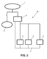
- FIG. 2 depicts another dedicated electrical installation (20) in which only the controllable loads (3') are therefore managed.
- This electrical installation (20) comprises a CCU or central control unit (5) in the head-end of the electrical installation (20).
- the central control unit (5) is responsible for managing the available power, for which purpose it has all the information relating to the electrical installation (20), that information containing, for example, the number of loads, the nominal power of each load and/or the instantaneous consumption of each load, among others.
- the remaining consumption devices (2) are still considered outside the power management process of the charging stations.
- Figure 3 depicts a preferred embodiment in a non-dedicated electrical installation (30) which does not comprise a CCU in the head-end of the installation and therefore one or several controllable loads (3') are responsible for the self-management of the consumed energy. Since it is a non-dedicated electrical installation (30), it comprises other loads forming non-controllable loads (2'), these being able to be the consumption devices (2) of a residence, shopping mall and/or service station, among others. In these situations, the maximum power capacity parameter is configured such that if said margin is not exceeded, the electrical installation (30) has enough capacity for supplying power to the non-controllable loads.
- Figure 4a depicts a generic non-dedicated electrical installation (40) with a central control unit (5) in the head-end.
- the central control unit (5) manages the consumption of all the connected controllable loads (3'), dynamically having to that end the information relating to the number of controllable loads (3'), the nominal power of each load, the status of each load, the instantaneous consumptions of each load, the installation capacity and the instantaneous consumption of the non-controllable loads (2'). This allows the proposed method for managing power to be dynamically adapted to the conditions of the electrical installation (40).
- FIG. 4b A more particular case of a non-dedicated installation such as that of Figure 4a is depicted in Figure 4b , where the electrical installation (40') is formed by:
- the central control unit (5) dynamically has the information relating to the number of controllable loads (3') and the number of controllable sources (7, 9), the nominal power of each of said loads and sources, the status of each of them, the instantaneous consumptions of each of them, the installation capacity and the instantaneous consumption of the non-controllable loads (2'). With this information, in addition to controlling the connection/disconnection and/or regulation of the controllable loads (3'), the central control unit (5) regulates the connection/disconnection and generation of the controllable sources (7, 9).
- the maximum available power will depend, in each instant, on the status of the grid or electric line (1) and on the generation capacity of the controllable sources (7, 9).
- priority is given to the consumed energy coming from renewable energy sources (11, 12), regulating the power generated by these sources with respect to the necessary consumption of the present loads (2', 3').
- the intelligent meter informs of this situation and the central control unit (5) commands the hybrid system (9) to generate the necessary energy and thus prevent interrupting the consumption of the loads.
- the hybrid system (9) in turn gives priority to its generated power coming from renewable energy sources (11,12) and regulates the power generated by them with respect to the instantaneous consumption of the loads (2', 3'), it further being possible to have a supporting generator such as the combustion group for exceptional situations in which the consumed power could not be supplied by other sources.
- the hybrid system (9) depicted in Figure 4b is further provided with an intermediate storage battery (13); this battery is charged while the consumptions are less than the available power of the power grid (1) and the controllable sources (7,11,12), and it is used as an additional power supply in the instant in which the available power is less than the consumptions of the loads; the battery (13) becoming one that can supply part of the available power of the installation (40').
- At least one of the controllable loads (3'), for example a charging station (3) can adopt the functions of a central control unit (5).
- Figure 5 depicts the main operations performed by the central control unit (5).
- the maximum power set-point or reference value (51) of the installation (10, 20, 30, 40, 40') is determined, establishing a safety margin based on that value, and the connection or disconnection of the controllable loads (3, 3') and the maximum initial current reference (53) for each connected load are determined (52) according to that set-point, without exceeding the maximum power depending on the number of controllable loads (3').
- the instantaneous consumptions of the connected controllable loads (3') are continuously controlled (54).
- the total power consumption is compared with the safety margin established with respect to the maximum power set-point, which is a variable that can be configured by the installation administrator, who can set the value thereof in real time to adapt the consumption of the installation in the event of power grid saturation.
- a preferred embodiment of the present invention relates to a method for managing power consumed in electrical installations (10, 20, 30, 40, 40'), which comprises determining (52) whether at least one controllable load (3') or controllable source (7, 9) of the electrical installation (10, 20, 30, 40, 40') is connected to or disconnected from an electric line (1) of the electrical installation (10, 20, 30, 40, 40'), characterized in that it further comprises:
- the step of determining (52) whether at least one controllable load (3') of the electrical installation (10, 20, 30, 40, 40') is connected to or disconnected from the electric line (1) can be performed taking into account some of the following factors or a combination thereof:
- the total power consumption does not exceed (54") the maximum power set-point and the consumption of a controllable load (3') is less than that assigned, the total consumption is also reset following the steps illustrated in Figure 7 for an efficient management of the available power.
- the step of updating (54) the instantaneous consumptions of the controllable loads (3') is performed again.
- the resetting process is the one shown in Figure 8 .
- Figure 9 shows the reception of a new request to connect a new controllable load (91) which involves recalculating the available power at that time (92).
- Management by "time of use” is based on using each controllable load (3') "in shifts” when it approaches or when it is expected to exceed the total line connection power limit with a safety margin of the electrical installation.
- the installation (20, 40, 40') consists of a central control unit (5) and different connection points for controllable loads (3') distributed and intercommunicated with one another.
- the central control unit (5) instantaneously controls the load parameters, total consumption and individual consumption in the installation.
- the central control unit (5) knows at all times the power available in the line connection, which is equal to the total line connection power minus the total consumption of the loads: (line connection power - consumption).
- condition 1 is not complied with and if a control by time of use (85) is performed, whether a controllable load (3') has a time of use (851) which exceeds a maximum time (851'), or whether a controllable load is expected to go beyond said time maximum (851") is checked, and in such case, the connection (852) of the load with that time of use is interrupted and the power available at that time (82) is again calculated.
- controllable load (3') measures a series of parameters comprising the intensity and/or power being consumed at all times.
- the charging station or controlled load (3, 3') informs the central control unit (5) of these parameters. Therefore, the decision parameters established for managing charging are always based on real time consumptions of the installation and not on "current assignments" or "nominal power of each load" which would not optimize the use of the installation capacity.
- any consumption session has a connection point time of use counter, therefore, when the preceding "condition 1" is not complied with, i.e., more total power than that available is required, it can become a management of using the power grid in shifts according to Figure 6 .
- the controllable load (3') with the greater time of use (63) is disconnected and it is again verified (64) whether the total consumption exceeds the total line connection power after disconnecting the load: consumption > line connection power. If so (64"), loads remain disconnected according to the criterion of greater time of use and if not (64') the instantaneous consumptions of the connected loads (65) are calculated again, i.e., going back to step (54) of Figure 5 .
- the method allows parametrizing maximum times of use and allows prioritizing by levels. If the available power is less than the power of the last load which has made a request to connect, the load of that vehicle (6) or controllable load (3') with greater time of use is interrupted. Optionally, a criterion by priority assigned to the controllable loads (3') can also be followed and the disconnection of the load with greater time of use and lower priority level is performed.
- the connection priority levels for the loads can be established by different parameters such as: user level and/or preferred connection timetable according to the load type, among others. The latter disconnection action is repeated until "condition 1" is complied with.
- the vehicles or controllable loads (3') the load of which has been interrupted are connected again when other vehicles (6) or controllable loads (3') gradually reach the maximum time of use. For example, priority is given to vehicles (6) in line with less time of use for loads (3') with the same priority level.
- the time of use counters are only refreshed at the end of the consumption session.
- the method for managing power assures the disconnection of the charging stations (3) or controllable loads (3') necessary to prevent tripping the magnetothermal protection protecting the line connection of the circuit, thus preventing leaving the entire circuit without a power supply.
- one of the configurable parameters of the installation can be a type of protection trip curve for the installation.
- the loads (3') can be disconnected to prevent tripping in the protections of the installation which affect other loads present.
- the installation (20, 40, 40') consists of a central control unit (5) and different connection points distributed and intercommunicated with one another.
- the central control unit (5) instantaneously controls the load parameters, total consumption and individual consumption in the installation and knows the power available in the line connection at all times: line connection power - consumption. Therefore, in the request to connect a new load according to the resetting process shown in Figure 8 , if the available power is greater than the nominal power of said load which has made the request (82), the central control unit (5) will command it to proceed to connection. This situation will occur for subsequent requests to connect other loads as long as the following condition is complied with: Condition 1: (Connection line power - consumption) > load nominal power
- the charging station (3) measures the intensity and/or power that is being transferred to the vehicle (6) or controllable load (3') at all times and informs the central control unit (5) which recalculates the maximum current reference of each load taking into account the new request (861) according to the preceding expression. Therefore, the decision parameters established for managing the charging are always based on the real time consumptions of the installation and not on the "current assignments", the Iload or the nominal power of each charging station or controllable load", which would not optimize the use of the installation capacity.
- the central control unit (5) authorizes the connection of the controllable load (3') and recalculates the available current (862) to then reassign said current (863) to the new connected controllable load (3').
- connection priority levels can be assigned for the loads, establishing the priorities through different parameters such as user level, preferred connection timetable according to the load type,... etc. This can mean that there may be loads the current assignment of which must always be the greatest possible due to having the highest priority level.
- the resetting shown in Figure 6 is performed, which for the case of control based on available current (66) involves, as described, recalculating the maximum reference of the maximum current of each of the loads (67) and updating its instantaneous consumptions (65) again.
- the method for managing power assures the reassignment of available current for each charging station in order to prevent tripping the magnetothermal protection protecting the line connection of the circuit, thus preventing leaving the entire circuit without a power supply.
- one of the configurable parameters of the installation can be a type of protection trip curve for the installation.
- the loads are regulated to lower consumptions to preventing tripping in the protections of the installation which affect other loads present.
- Both types of management are applied to any type of controllable loads (3') present in the installation, being able to be combined, for example, in a residence, being able to regulate the heating, the charging of an electric vehicle, to connect/disconnect specific loads - washing machine...- etc.
Landscapes
- Engineering & Computer Science (AREA)
- Power Engineering (AREA)
- Transportation (AREA)
- Mechanical Engineering (AREA)
- Supply And Distribution Of Alternating Current (AREA)
- Remote Monitoring And Control Of Power-Distribution Networks (AREA)
Applications Claiming Priority (1)
| Application Number | Priority Date | Filing Date | Title |
|---|---|---|---|
| PCT/ES2012/070890 WO2014096468A1 (es) | 2012-12-20 | 2012-12-20 | Método para la gestión de potencia en instalaciones eléctricas |
Publications (2)
| Publication Number | Publication Date |
|---|---|
| EP2937243A1 true EP2937243A1 (de) | 2015-10-28 |
| EP2937243B1 EP2937243B1 (de) | 2020-03-18 |
Family
ID=47749881
Family Applications (1)
| Application Number | Title | Priority Date | Filing Date |
|---|---|---|---|
| EP12826619.4A Active EP2937243B1 (de) | 2012-12-20 | 2012-12-20 | Método para la gestión de potencia en instalaciones eléctricas |
Country Status (3)
| Country | Link |
|---|---|
| EP (1) | EP2937243B1 (de) |
| ES (1) | ES2785093T3 (de) |
| WO (1) | WO2014096468A1 (de) |
Cited By (3)
| Publication number | Priority date | Publication date | Assignee | Title |
|---|---|---|---|---|
| CN105818710A (zh) * | 2016-05-20 | 2016-08-03 | 武汉中原弘仁新能源科技有限公司 | 基于云计算后台系统精准充电的充电桩及充电方法 |
| US10291024B2 (en) | 2014-11-04 | 2019-05-14 | Abb Schweiz Ag | Control of a microgrid |
| EP3713040A1 (de) * | 2019-03-20 | 2020-09-23 | Toyota Jidosha Kabushiki Kaisha | Vorrichtung zur steuerung von angebot und nachfrage |
Families Citing this family (1)
| Publication number | Priority date | Publication date | Assignee | Title |
|---|---|---|---|---|
| ES2609074B1 (es) * | 2015-10-09 | 2017-12-26 | Joan Comellas Cabeza | Procedimiento y sistema de control de consumo para cargadores |
Family Cites Families (8)
| Publication number | Priority date | Publication date | Assignee | Title |
|---|---|---|---|---|
| JP2004015883A (ja) * | 2002-06-05 | 2004-01-15 | Mitsubishi Heavy Ind Ltd | 安定化電力供給システムおよびその運用方法、並びに電力安定供給の運用プログラム |
| EP2041853B1 (de) * | 2007-04-17 | 2013-08-07 | Cooper, Timothy Patrick | Lastverwaltungssteuergerät für eine elektrische haushaltsanlage |
| US8013570B2 (en) | 2009-07-23 | 2011-09-06 | Coulomb Technologies, Inc. | Electrical circuit sharing for electric vehicle charging stations |
| JP4836213B2 (ja) * | 2009-08-31 | 2011-12-14 | トヨタ自動車株式会社 | 電力供給システム |
| JP2011125122A (ja) * | 2009-12-09 | 2011-06-23 | Sony Corp | バッテリ制御システム、バッテリ制御装置、バッテリ制御方法およびプログラム |
| US9878629B2 (en) | 2009-12-17 | 2018-01-30 | Chargepoint, Inc. | Method and apparatus for electric vehicle charging station load management in a residence |
| WO2011157974A1 (en) * | 2010-06-16 | 2011-12-22 | Rolls-Royce Plc | Charging system for an electric vehicle |
| JP5617578B2 (ja) * | 2010-12-03 | 2014-11-05 | ソニー株式会社 | 配電システム及び配電方法 |
-
2012
- 2012-12-20 EP EP12826619.4A patent/EP2937243B1/de active Active
- 2012-12-20 ES ES12826619T patent/ES2785093T3/es active Active
- 2012-12-20 WO PCT/ES2012/070890 patent/WO2014096468A1/es not_active Ceased
Cited By (8)
| Publication number | Priority date | Publication date | Assignee | Title |
|---|---|---|---|---|
| US10291024B2 (en) | 2014-11-04 | 2019-05-14 | Abb Schweiz Ag | Control of a microgrid |
| EP3216100B1 (de) * | 2014-11-04 | 2020-02-19 | ABB Schweiz AG | Steuerung eines mikronetzes |
| CN105818710A (zh) * | 2016-05-20 | 2016-08-03 | 武汉中原弘仁新能源科技有限公司 | 基于云计算后台系统精准充电的充电桩及充电方法 |
| CN105818710B (zh) * | 2016-05-20 | 2018-07-10 | 武汉中原弘仁新能源科技有限公司 | 基于云计算后台系统精准充电的充电桩及充电方法 |
| EP3713040A1 (de) * | 2019-03-20 | 2020-09-23 | Toyota Jidosha Kabushiki Kaisha | Vorrichtung zur steuerung von angebot und nachfrage |
| EP4030582A1 (de) * | 2019-03-20 | 2022-07-20 | Toyota Jidosha Kabushiki Kaisha | Vorrichtung zur steuerung von angebot und nachfrage |
| US11537156B2 (en) * | 2019-03-20 | 2022-12-27 | Toyota Jidosha Kabushiki Kaisha | Power supply-demand control device |
| US11899484B2 (en) | 2019-03-20 | 2024-02-13 | Toyota Jidosha Kabushiki Kaisha | Supply-demand control device |
Also Published As
| Publication number | Publication date |
|---|---|
| ES2785093T3 (es) | 2020-10-05 |
| WO2014096468A1 (es) | 2014-06-26 |
| EP2937243B1 (de) | 2020-03-18 |
Similar Documents
| Publication | Publication Date | Title |
|---|---|---|
| EP3979452B1 (de) | System zum routen einer intelligenten ladeenergiequelle und implementierungsverfahren dafür | |
| US8326467B2 (en) | Controller and method of controlling a power system | |
| US9205756B2 (en) | Battery system | |
| EP2587608B1 (de) | System, Ladevorrichtung und Verfahren zum Laden einer Stromspeichervorrichtung | |
| US9906025B2 (en) | Electric power supply apparatus and system | |
| US20230406137A1 (en) | Charge control device, charge system, charge control method, and program | |
| US11749991B1 (en) | Energy management for connected charging stations with bidirectionality | |
| AU2020255899B2 (en) | Power management system | |
| EP2937243B1 (de) | Método para la gestión de potencia en instalaciones eléctricas | |
| CN109936145A (zh) | 适用于园区配电的充电站负荷调整方法 | |
| EP4037129A1 (de) | Stromverwaltungssystem, server und stromangebots- und -bedarfsanpassungsverfahren | |
| CN112865156B (zh) | 储能系统以及电力系统 | |
| US12103423B2 (en) | Resilient charging station | |
| CN112952904A (zh) | 基于储充一体化电力系统的控制方法及装置 | |
| US10886744B2 (en) | Power conversion system, power supply system and power conversion device | |
| CN104272548A (zh) | 电力管理装置、电力管理系统以及电力管理方法 | |
| JP2024029489A (ja) | 充放電制御システム及び充放電制御プログラム | |
| US20200343726A1 (en) | Power management method and power management apparatus | |
| US12558984B2 (en) | Resilient charging station | |
| US12194881B2 (en) | Energy management for multiple charging stations | |
| JP2018046709A (ja) | 電力需給管理装置 | |
| Hamidi et al. | A distributed control system for enhancing smart-grid resiliency using electric vehicles | |
| JP2023153468A (ja) | 電力システム | |
| US20210376611A1 (en) | A method and system for power balancing | |
| CN118971075A (zh) | 一种工商业储能的充放电管理系统及管理方法 |
Legal Events
| Date | Code | Title | Description |
|---|---|---|---|
| PUAI | Public reference made under article 153(3) epc to a published international application that has entered the european phase |
Free format text: ORIGINAL CODE: 0009012 |
|
| 17P | Request for examination filed |
Effective date: 20150615 |
|
| AK | Designated contracting states |
Kind code of ref document: A1 Designated state(s): AL AT BE BG CH CY CZ DE DK EE ES FI FR GB GR HR HU IE IS IT LI LT LU LV MC MK MT NL NO PL PT RO RS SE SI SK SM TR |
|
| AX | Request for extension of the european patent |
Extension state: BA ME |
|
| DAX | Request for extension of the european patent (deleted) | ||
| STAA | Information on the status of an ep patent application or granted ep patent |
Free format text: STATUS: EXAMINATION IS IN PROGRESS |
|
| 17Q | First examination report despatched |
Effective date: 20161206 |
|
| REG | Reference to a national code |
Ref country code: DE Ref legal event code: R079 Ref document number: 602012068619 Country of ref document: DE Free format text: PREVIOUS MAIN CLASS: B60L0011000000 Ipc: B60L0053000000 |
|
| RIC1 | Information provided on ipc code assigned before grant |
Ipc: H02J 3/38 20060101ALI20191121BHEP Ipc: H02J 7/00 20060101ALI20191121BHEP Ipc: B60L 53/00 20190101AFI20191121BHEP Ipc: H02J 3/14 20060101ALI20191121BHEP |
|
| GRAP | Despatch of communication of intention to grant a patent |
Free format text: ORIGINAL CODE: EPIDOSNIGR1 |
|
| STAA | Information on the status of an ep patent application or granted ep patent |
Free format text: STATUS: GRANT OF PATENT IS INTENDED |
|
| INTG | Intention to grant announced |
Effective date: 20200110 |
|
| GRAS | Grant fee paid |
Free format text: ORIGINAL CODE: EPIDOSNIGR3 |
|
| GRAA | (expected) grant |
Free format text: ORIGINAL CODE: 0009210 |
|
| STAA | Information on the status of an ep patent application or granted ep patent |
Free format text: STATUS: THE PATENT HAS BEEN GRANTED |
|
| AK | Designated contracting states |
Kind code of ref document: B1 Designated state(s): AL AT BE BG CH CY CZ DE DK EE ES FI FR GB GR HR HU IE IS IT LI LT LU LV MC MK MT NL NO PL PT RO RS SE SI SK SM TR |
|
| REG | Reference to a national code |
Ref country code: GB Ref legal event code: FG4D |
|
| REG | Reference to a national code |
Ref country code: DE Ref legal event code: R096 Ref document number: 602012068619 Country of ref document: DE |
|
| REG | Reference to a national code |
Ref country code: AT Ref legal event code: REF Ref document number: 1245532 Country of ref document: AT Kind code of ref document: T Effective date: 20200415 Ref country code: IE Ref legal event code: FG4D |
|
| PG25 | Lapsed in a contracting state [announced via postgrant information from national office to epo] |
Ref country code: NO Free format text: LAPSE BECAUSE OF FAILURE TO SUBMIT A TRANSLATION OF THE DESCRIPTION OR TO PAY THE FEE WITHIN THE PRESCRIBED TIME-LIMIT Effective date: 20200618 Ref country code: RS Free format text: LAPSE BECAUSE OF FAILURE TO SUBMIT A TRANSLATION OF THE DESCRIPTION OR TO PAY THE FEE WITHIN THE PRESCRIBED TIME-LIMIT Effective date: 20200318 Ref country code: FI Free format text: LAPSE BECAUSE OF FAILURE TO SUBMIT A TRANSLATION OF THE DESCRIPTION OR TO PAY THE FEE WITHIN THE PRESCRIBED TIME-LIMIT Effective date: 20200318 |
|
| REG | Reference to a national code |
Ref country code: NL Ref legal event code: MP Effective date: 20200318 |
|
| PG25 | Lapsed in a contracting state [announced via postgrant information from national office to epo] |
Ref country code: LV Free format text: LAPSE BECAUSE OF FAILURE TO SUBMIT A TRANSLATION OF THE DESCRIPTION OR TO PAY THE FEE WITHIN THE PRESCRIBED TIME-LIMIT Effective date: 20200318 Ref country code: SE Free format text: LAPSE BECAUSE OF FAILURE TO SUBMIT A TRANSLATION OF THE DESCRIPTION OR TO PAY THE FEE WITHIN THE PRESCRIBED TIME-LIMIT Effective date: 20200318 Ref country code: GR Free format text: LAPSE BECAUSE OF FAILURE TO SUBMIT A TRANSLATION OF THE DESCRIPTION OR TO PAY THE FEE WITHIN THE PRESCRIBED TIME-LIMIT Effective date: 20200619 Ref country code: BG Free format text: LAPSE BECAUSE OF FAILURE TO SUBMIT A TRANSLATION OF THE DESCRIPTION OR TO PAY THE FEE WITHIN THE PRESCRIBED TIME-LIMIT Effective date: 20200618 Ref country code: HR Free format text: LAPSE BECAUSE OF FAILURE TO SUBMIT A TRANSLATION OF THE DESCRIPTION OR TO PAY THE FEE WITHIN THE PRESCRIBED TIME-LIMIT Effective date: 20200318 |
|
| REG | Reference to a national code |
Ref country code: LT Ref legal event code: MG4D |
|
| PG25 | Lapsed in a contracting state [announced via postgrant information from national office to epo] |
Ref country code: NL Free format text: LAPSE BECAUSE OF FAILURE TO SUBMIT A TRANSLATION OF THE DESCRIPTION OR TO PAY THE FEE WITHIN THE PRESCRIBED TIME-LIMIT Effective date: 20200318 |
|
| REG | Reference to a national code |
Ref country code: ES Ref legal event code: FG2A Ref document number: 2785093 Country of ref document: ES Kind code of ref document: T3 Effective date: 20201005 |
|
| PG25 | Lapsed in a contracting state [announced via postgrant information from national office to epo] |
Ref country code: LT Free format text: LAPSE BECAUSE OF FAILURE TO SUBMIT A TRANSLATION OF THE DESCRIPTION OR TO PAY THE FEE WITHIN THE PRESCRIBED TIME-LIMIT Effective date: 20200318 Ref country code: PT Free format text: LAPSE BECAUSE OF FAILURE TO SUBMIT A TRANSLATION OF THE DESCRIPTION OR TO PAY THE FEE WITHIN THE PRESCRIBED TIME-LIMIT Effective date: 20200812 Ref country code: EE Free format text: LAPSE BECAUSE OF FAILURE TO SUBMIT A TRANSLATION OF THE DESCRIPTION OR TO PAY THE FEE WITHIN THE PRESCRIBED TIME-LIMIT Effective date: 20200318 Ref country code: SM Free format text: LAPSE BECAUSE OF FAILURE TO SUBMIT A TRANSLATION OF THE DESCRIPTION OR TO PAY THE FEE WITHIN THE PRESCRIBED TIME-LIMIT Effective date: 20200318 Ref country code: SK Free format text: LAPSE BECAUSE OF FAILURE TO SUBMIT A TRANSLATION OF THE DESCRIPTION OR TO PAY THE FEE WITHIN THE PRESCRIBED TIME-LIMIT Effective date: 20200318 Ref country code: RO Free format text: LAPSE BECAUSE OF FAILURE TO SUBMIT A TRANSLATION OF THE DESCRIPTION OR TO PAY THE FEE WITHIN THE PRESCRIBED TIME-LIMIT Effective date: 20200318 Ref country code: IS Free format text: LAPSE BECAUSE OF FAILURE TO SUBMIT A TRANSLATION OF THE DESCRIPTION OR TO PAY THE FEE WITHIN THE PRESCRIBED TIME-LIMIT Effective date: 20200718 Ref country code: CZ Free format text: LAPSE BECAUSE OF FAILURE TO SUBMIT A TRANSLATION OF THE DESCRIPTION OR TO PAY THE FEE WITHIN THE PRESCRIBED TIME-LIMIT Effective date: 20200318 |
|
| REG | Reference to a national code |
Ref country code: AT Ref legal event code: MK05 Ref document number: 1245532 Country of ref document: AT Kind code of ref document: T Effective date: 20200318 |
|
| REG | Reference to a national code |
Ref country code: DE Ref legal event code: R097 Ref document number: 602012068619 Country of ref document: DE |
|
| PLBE | No opposition filed within time limit |
Free format text: ORIGINAL CODE: 0009261 |
|
| STAA | Information on the status of an ep patent application or granted ep patent |
Free format text: STATUS: NO OPPOSITION FILED WITHIN TIME LIMIT |
|
| PG25 | Lapsed in a contracting state [announced via postgrant information from national office to epo] |
Ref country code: AT Free format text: LAPSE BECAUSE OF FAILURE TO SUBMIT A TRANSLATION OF THE DESCRIPTION OR TO PAY THE FEE WITHIN THE PRESCRIBED TIME-LIMIT Effective date: 20200318 Ref country code: DK Free format text: LAPSE BECAUSE OF FAILURE TO SUBMIT A TRANSLATION OF THE DESCRIPTION OR TO PAY THE FEE WITHIN THE PRESCRIBED TIME-LIMIT Effective date: 20200318 |
|
| 26N | No opposition filed |
Effective date: 20201221 |
|
| PG25 | Lapsed in a contracting state [announced via postgrant information from national office to epo] |
Ref country code: PL Free format text: LAPSE BECAUSE OF FAILURE TO SUBMIT A TRANSLATION OF THE DESCRIPTION OR TO PAY THE FEE WITHIN THE PRESCRIBED TIME-LIMIT Effective date: 20200318 |
|
| PG25 | Lapsed in a contracting state [announced via postgrant information from national office to epo] |
Ref country code: SI Free format text: LAPSE BECAUSE OF FAILURE TO SUBMIT A TRANSLATION OF THE DESCRIPTION OR TO PAY THE FEE WITHIN THE PRESCRIBED TIME-LIMIT Effective date: 20200318 |
|
| REG | Reference to a national code |
Ref country code: DE Ref legal event code: R119 Ref document number: 602012068619 Country of ref document: DE |
|
| REG | Reference to a national code |
Ref country code: CH Ref legal event code: PL |
|
| GBPC | Gb: european patent ceased through non-payment of renewal fee |
Effective date: 20201220 |
|
| PG25 | Lapsed in a contracting state [announced via postgrant information from national office to epo] |
Ref country code: MC Free format text: LAPSE BECAUSE OF FAILURE TO SUBMIT A TRANSLATION OF THE DESCRIPTION OR TO PAY THE FEE WITHIN THE PRESCRIBED TIME-LIMIT Effective date: 20200318 |
|
| REG | Reference to a national code |
Ref country code: BE Ref legal event code: MM Effective date: 20201231 |
|
| PG25 | Lapsed in a contracting state [announced via postgrant information from national office to epo] |
Ref country code: IE Free format text: LAPSE BECAUSE OF NON-PAYMENT OF DUE FEES Effective date: 20201220 Ref country code: LU Free format text: LAPSE BECAUSE OF NON-PAYMENT OF DUE FEES Effective date: 20201220 |
|
| PG25 | Lapsed in a contracting state [announced via postgrant information from national office to epo] |
Ref country code: LI Free format text: LAPSE BECAUSE OF NON-PAYMENT OF DUE FEES Effective date: 20201231 Ref country code: CH Free format text: LAPSE BECAUSE OF NON-PAYMENT OF DUE FEES Effective date: 20201231 Ref country code: GB Free format text: LAPSE BECAUSE OF NON-PAYMENT OF DUE FEES Effective date: 20201220 Ref country code: DE Free format text: LAPSE BECAUSE OF NON-PAYMENT OF DUE FEES Effective date: 20210701 |
|
| PG25 | Lapsed in a contracting state [announced via postgrant information from national office to epo] |
Ref country code: TR Free format text: LAPSE BECAUSE OF FAILURE TO SUBMIT A TRANSLATION OF THE DESCRIPTION OR TO PAY THE FEE WITHIN THE PRESCRIBED TIME-LIMIT Effective date: 20200318 Ref country code: MT Free format text: LAPSE BECAUSE OF FAILURE TO SUBMIT A TRANSLATION OF THE DESCRIPTION OR TO PAY THE FEE WITHIN THE PRESCRIBED TIME-LIMIT Effective date: 20200318 Ref country code: CY Free format text: LAPSE BECAUSE OF FAILURE TO SUBMIT A TRANSLATION OF THE DESCRIPTION OR TO PAY THE FEE WITHIN THE PRESCRIBED TIME-LIMIT Effective date: 20200318 |
|
| PG25 | Lapsed in a contracting state [announced via postgrant information from national office to epo] |
Ref country code: MK Free format text: LAPSE BECAUSE OF FAILURE TO SUBMIT A TRANSLATION OF THE DESCRIPTION OR TO PAY THE FEE WITHIN THE PRESCRIBED TIME-LIMIT Effective date: 20200318 Ref country code: AL Free format text: LAPSE BECAUSE OF FAILURE TO SUBMIT A TRANSLATION OF THE DESCRIPTION OR TO PAY THE FEE WITHIN THE PRESCRIBED TIME-LIMIT Effective date: 20200318 |
|
| PG25 | Lapsed in a contracting state [announced via postgrant information from national office to epo] |
Ref country code: BE Free format text: LAPSE BECAUSE OF NON-PAYMENT OF DUE FEES Effective date: 20201231 |
|
| PGFP | Annual fee paid to national office [announced via postgrant information from national office to epo] |
Ref country code: ES Payment date: 20250102 Year of fee payment: 13 |
|
| PG25 | Lapsed in a contracting state [announced via postgrant information from national office to epo] |
Ref country code: IS Free format text: LAPSE BECAUSE OF NON-PAYMENT OF DUE FEES Effective date: 20200718 |
|
| PGFP | Annual fee paid to national office [announced via postgrant information from national office to epo] |
Ref country code: IT Payment date: 20251223 Year of fee payment: 14 |
|
| PGFP | Annual fee paid to national office [announced via postgrant information from national office to epo] |
Ref country code: FR Payment date: 20251118 Year of fee payment: 14 |