EP2937163A1 - Machine and method for additive manufacturing - Google Patents
Machine and method for additive manufacturing Download PDFInfo
- Publication number
- EP2937163A1 EP2937163A1 EP15158338.2A EP15158338A EP2937163A1 EP 2937163 A1 EP2937163 A1 EP 2937163A1 EP 15158338 A EP15158338 A EP 15158338A EP 2937163 A1 EP2937163 A1 EP 2937163A1
- Authority
- EP
- European Patent Office
- Prior art keywords
- electron beam
- electron gun
- powdered material
- additive manufacturing
- metal powder
- Prior art date
- Legal status (The legal status is an assumption and is not a legal conclusion. Google has not performed a legal analysis and makes no representation as to the accuracy of the status listed.)
- Granted
Links
Images


Classifications
-
- B—PERFORMING OPERATIONS; TRANSPORTING
- B29—WORKING OF PLASTICS; WORKING OF SUBSTANCES IN A PLASTIC STATE IN GENERAL
- B29C—SHAPING OR JOINING OF PLASTICS; SHAPING OF MATERIAL IN A PLASTIC STATE, NOT OTHERWISE PROVIDED FOR; AFTER-TREATMENT OF THE SHAPED PRODUCTS, e.g. REPAIRING
- B29C64/00—Additive manufacturing, i.e. manufacturing of three-dimensional [3D] objects by additive deposition, additive agglomeration or additive layering, e.g. by 3D printing, stereolithography or selective laser sintering
- B29C64/10—Processes of additive manufacturing
- B29C64/141—Processes of additive manufacturing using only solid materials
- B29C64/153—Processes of additive manufacturing using only solid materials using layers of powder being selectively joined, e.g. by selective laser sintering or melting
-
- B—PERFORMING OPERATIONS; TRANSPORTING
- B22—CASTING; POWDER METALLURGY
- B22F—WORKING METALLIC POWDER; MANUFACTURE OF ARTICLES FROM METALLIC POWDER; MAKING METALLIC POWDER; APPARATUS OR DEVICES SPECIALLY ADAPTED FOR METALLIC POWDER
- B22F10/00—Additive manufacturing of workpieces or articles from metallic powder
- B22F10/20—Direct sintering or melting
- B22F10/28—Powder bed fusion, e.g. selective laser melting [SLM] or electron beam melting [EBM]
-
- B—PERFORMING OPERATIONS; TRANSPORTING
- B22—CASTING; POWDER METALLURGY
- B22F—WORKING METALLIC POWDER; MANUFACTURE OF ARTICLES FROM METALLIC POWDER; MAKING METALLIC POWDER; APPARATUS OR DEVICES SPECIALLY ADAPTED FOR METALLIC POWDER
- B22F12/00—Apparatus or devices specially adapted for additive manufacturing; Auxiliary means for additive manufacturing; Combinations of additive manufacturing apparatus or devices with other processing apparatus or devices
- B22F12/40—Radiation means
- B22F12/44—Radiation means characterised by the configuration of the radiation means
- B22F12/45—Two or more
-
- B—PERFORMING OPERATIONS; TRANSPORTING
- B23—MACHINE TOOLS; METAL-WORKING NOT OTHERWISE PROVIDED FOR
- B23K—SOLDERING OR UNSOLDERING; WELDING; CLADDING OR PLATING BY SOLDERING OR WELDING; CUTTING BY APPLYING HEAT LOCALLY, e.g. FLAME CUTTING; WORKING BY LASER BEAM
- B23K15/00—Electron-beam welding or cutting
- B23K15/004—Tandem beams or torches, i.e. working simultaneously with several beams or torches
-
- B—PERFORMING OPERATIONS; TRANSPORTING
- B23—MACHINE TOOLS; METAL-WORKING NOT OTHERWISE PROVIDED FOR
- B23K—SOLDERING OR UNSOLDERING; WELDING; CLADDING OR PLATING BY SOLDERING OR WELDING; CUTTING BY APPLYING HEAT LOCALLY, e.g. FLAME CUTTING; WORKING BY LASER BEAM
- B23K15/00—Electron-beam welding or cutting
- B23K15/0046—Welding
- B23K15/0086—Welding welding for purposes other than joining, e.g. build-up welding
-
- B—PERFORMING OPERATIONS; TRANSPORTING
- B33—ADDITIVE MANUFACTURING TECHNOLOGY
- B33Y—ADDITIVE MANUFACTURING, i.e. MANUFACTURING OF THREE-DIMENSIONAL [3D] OBJECTS BY ADDITIVE DEPOSITION, ADDITIVE AGGLOMERATION OR ADDITIVE LAYERING, e.g. BY 3D PRINTING, STEREOLITHOGRAPHY OR SELECTIVE LASER SINTERING
- B33Y10/00—Processes of additive manufacturing
-
- B—PERFORMING OPERATIONS; TRANSPORTING
- B33—ADDITIVE MANUFACTURING TECHNOLOGY
- B33Y—ADDITIVE MANUFACTURING, i.e. MANUFACTURING OF THREE-DIMENSIONAL [3D] OBJECTS BY ADDITIVE DEPOSITION, ADDITIVE AGGLOMERATION OR ADDITIVE LAYERING, e.g. BY 3D PRINTING, STEREOLITHOGRAPHY OR SELECTIVE LASER SINTERING
- B33Y30/00—Apparatus for additive manufacturing; Details thereof or accessories therefor
-
- B—PERFORMING OPERATIONS; TRANSPORTING
- B22—CASTING; POWDER METALLURGY
- B22F—WORKING METALLIC POWDER; MANUFACTURE OF ARTICLES FROM METALLIC POWDER; MAKING METALLIC POWDER; APPARATUS OR DEVICES SPECIALLY ADAPTED FOR METALLIC POWDER
- B22F12/00—Apparatus or devices specially adapted for additive manufacturing; Auxiliary means for additive manufacturing; Combinations of additive manufacturing apparatus or devices with other processing apparatus or devices
- B22F12/30—Platforms or substrates
-
- B—PERFORMING OPERATIONS; TRANSPORTING
- B22—CASTING; POWDER METALLURGY
- B22F—WORKING METALLIC POWDER; MANUFACTURE OF ARTICLES FROM METALLIC POWDER; MAKING METALLIC POWDER; APPARATUS OR DEVICES SPECIALLY ADAPTED FOR METALLIC POWDER
- B22F2202/00—Treatment under specific physical conditions
-
- B—PERFORMING OPERATIONS; TRANSPORTING
- B22—CASTING; POWDER METALLURGY
- B22F—WORKING METALLIC POWDER; MANUFACTURE OF ARTICLES FROM METALLIC POWDER; MAKING METALLIC POWDER; APPARATUS OR DEVICES SPECIALLY ADAPTED FOR METALLIC POWDER
- B22F2202/00—Treatment under specific physical conditions
- B22F2202/11—Use of irradiation
-
- B—PERFORMING OPERATIONS; TRANSPORTING
- B22—CASTING; POWDER METALLURGY
- B22F—WORKING METALLIC POWDER; MANUFACTURE OF ARTICLES FROM METALLIC POWDER; MAKING METALLIC POWDER; APPARATUS OR DEVICES SPECIALLY ADAPTED FOR METALLIC POWDER
- B22F2998/00—Supplementary information concerning processes or compositions relating to powder metallurgy
-
- B—PERFORMING OPERATIONS; TRANSPORTING
- B22—CASTING; POWDER METALLURGY
- B22F—WORKING METALLIC POWDER; MANUFACTURE OF ARTICLES FROM METALLIC POWDER; MAKING METALLIC POWDER; APPARATUS OR DEVICES SPECIALLY ADAPTED FOR METALLIC POWDER
- B22F3/00—Manufacture of workpieces or articles from metallic powder characterised by the manner of compacting or sintering; Apparatus specially adapted therefor ; Presses and furnaces
- B22F3/10—Sintering only
- B22F3/105—Sintering only by using electric current other than for infrared radiant energy, laser radiation or plasma ; by ultrasonic bonding
-
- B—PERFORMING OPERATIONS; TRANSPORTING
- B23—MACHINE TOOLS; METAL-WORKING NOT OTHERWISE PROVIDED FOR
- B23K—SOLDERING OR UNSOLDERING; WELDING; CLADDING OR PLATING BY SOLDERING OR WELDING; CUTTING BY APPLYING HEAT LOCALLY, e.g. FLAME CUTTING; WORKING BY LASER BEAM
- B23K15/00—Electron-beam welding or cutting
-
- Y—GENERAL TAGGING OF NEW TECHNOLOGICAL DEVELOPMENTS; GENERAL TAGGING OF CROSS-SECTIONAL TECHNOLOGIES SPANNING OVER SEVERAL SECTIONS OF THE IPC; TECHNICAL SUBJECTS COVERED BY FORMER USPC CROSS-REFERENCE ART COLLECTIONS [XRACs] AND DIGESTS
- Y02—TECHNOLOGIES OR APPLICATIONS FOR MITIGATION OR ADAPTATION AGAINST CLIMATE CHANGE
- Y02P—CLIMATE CHANGE MITIGATION TECHNOLOGIES IN THE PRODUCTION OR PROCESSING OF GOODS
- Y02P10/00—Technologies related to metal processing
- Y02P10/25—Process efficiency
Definitions
- the present invention relates to a machine and method for 'additive manufacturing', fabricating a three-dimensional object by spreading a powdered material on a support stage to form a thin layer of the powdered material and stacking such layers on top of each other.
- FIG. 4 is a schematic cross section of a related art additive manufacturing machine, 100.
- the additive manufacturing machine 100 spreads a metal powder M1 tightly on the top surface of a powder support stage 104 using a powder feeder 107 to form one layer. Then, only a two-dimensional structural portion of the metal powder M1 which has been spread tightly on the stage 104 and which corresponds to one cross section of a three-dimensional object P1 to be created is molten with an electron beam.
- the three-dimensional object is built by stacking such layers of the metal powder M1 on top of each other in the direction of height (in the Z-direction).
- the additive manufacturing machine 100 has an electron gun 108 mounted in the top of a vacuum vessel 102.
- a cylindrical additive manufacturing platform 103 is mounted inside the vacuum vessel 102.
- An electron beam controller 111 for controlling the electron gun 108 is connected with the electron gun 108.
- the platform 103 is centrally provided with a pit 103a.
- a drive mechanism 105 by which the stage 104 is movably supported is mounted below the pit 103a.
- the support stage 104 has a shaft portion 104d to which the drive mechanism 105 is coupled to drive the stage 104 in the vertical direction.
- the interior of the vacuum vessel 102 is maintained at a vacuum.
- the support stage 104 is placed by the drive mechanism 105 at a position that is lower than the top surface of the additive manufacturing platform 103 by a distance of ⁇ Z.
- the metal powder M1 is spread tightly up to a thickness equal to the distance ⁇ Z on the stage 104 by the powder feeder 107.
- a previously prepared, designed three-dimensional model is sliced into multiple two-dimensional shapes which are spaced from each other at intervals of ⁇ Z.
- an electron beam L1 is directed from the electron gun 108 at the metal powder M1.
- the region of the metal powder M1 conforming to the two-dimensional shape is molten by the electron beam L1 emitted from the electron gun 108.
- the molten metal powder M1 solidifies.
- the support stage 104 is lowered an incremental distance equal to ⁇ Z by the drive mechanism 105.
- an amount of the metal powder M1 for achieving a thickness of ⁇ Z is spread tightly on the lower layer formed immediately previously.
- the region of the metal powder M1 corresponding to the two-dimensional shape corresponding to this layer is illuminated with the electron beam L1 to melt and solidify the metal powder M1.
- This series of steps is repeated to stack layers of the molten and solidified metal powder M1 on top of each other, thus creating a three-dimensional object.
- Patent document 1 JP-T-2010-526694
- FIG. 3A schematically shows the state of electrons when the metal powder M1 is illuminated with the electron beam L1.
- the additive manufacturing machine 100 shown in FIG. 4 when the electron beam L1 impinges substantially perpendicularly on the sample surface, most of the impinging electrons penetrate into the sample surface and diffuse into the sample layer located under the metal powder M1 spread tightly as shown in FIG. 3A . Some electrons stay in the metal powder M1.
- the metal powder M1 is an insulator
- the metal powder M1 is negatively charged by the electron beam L1.
- the metal powder M1 is a conductor
- the grains of the powder each have a small ground contact area, are spherical in shape, and make a point contact with each other, then the powder is negatively charged in the same way as for an insulator, because the amount of current of the electron beam L1 is large. Therefore, as shown in FIG. 5 , the negatively charged grains of the metal powder M1 repel each other. This creates the danger that the powder M1 will be scattered.
- An additive manufacturing machine which solves the foregoing problems and achieves the above-described object of the invention has a support stage, a first electron gun, and a second electron gun.
- a powdered material for creating a three-dimensional (3D) object is spread tightly on the support stage.
- the first electron gun emits an electron beam at a given region of the powdered material that has been spread tightly on the support stage to melt the given region of the material.
- the second electron gun emits an electron beam at a sample surface formed by the powdered material spread tightly while the beam is tilted relative to the sample surface. Thus, static electricity on the powdered material is eliminated.
- An additive manufacturing method includes the following steps: (1) spreading a powdered material for creating a three-dimensional object tightly on one surface of a support stage; (2) illuminating a given region of the powdered material spread tightly on the support stage with an electron beam from a first electron gun to melt the given region of the powdered material; and (3) directing a second electron beam from a second electron gun different from the first electron gun at a sample surface formed by the powdered material spread tightly on the support stage while tilting the second electron beam to eliminate static electricity of the powdered material.
- static electricity on the powdered material can be eliminated by the second electron gun. Consequently, scattering of the powdered material due to static electricity can be prevented.
- FIGS. 1-3 An embodiment of the additive manufacturing machine of the present invention is hereinafter described with reference to FIGS. 1-3 .
- like components are indicated by like reference numerals.
- the various areas of the description are provided in the following order, the invention is not restricted to the following embodiment.
- FIG. 1 schematically shows the machine.
- the additive manufacturing machine, 1, shown in FIG. 1 is used to fabricate a multilayered three-dimensional object by illuminating a powdered material consisting of a metal powder of titanium, aluminum, iron, or other metal with an electron beam to melt the powdered material and stacking layers of the solidified powdered material on top of each other.
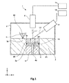
- the additive manufacturing machine 1 has a hollow vacuum vessel 2, an additive manufacturing frame 3, a support stage 4, a mechanical drive 5 by which the stage 4 is movably supported, a powder feeder 7 for supplying the metal powder M1 that is one example of powdered material onto the support stage 4, a first electron gun 8, and a second electron gun 9. Furthermore, the additive manufacturing machine 1 has a first electron beam controller 11 for controlling the first electron gun 8 and a second electron beam controller 12 for controlling the second electron gun 9.
- a vacuum pump (not shown) is connected with the vacuum vessel 2.
- the interior of the vacuum vessel 2 is maintained at a vacuum by evacuating the vacuum vessel 2 using the vacuum pump.
- the additive manufacturing frame 3, support stage 4, drive mechanism 5, and powder feeder 7 are mounted in the vacuum vessel 2.
- the additive manufacturing frame 3 is disposed in a lower part of the vacuum vessel 2.
- the frame 3 is provided with a pit 3a extending vertically through the frame.
- the pit 3a has an opening shaped like a square pole. A part of the outer periphery of the pit 3a is open to permit the completed 3D object P1 to be taken out.
- the support stage 4 and drive mechanism 5 are disposed in the pit 3a of the additive manufacturing frame 3.
- the support stage 4 is shaped like a flat plate.
- the metal powder M1 for creating the 3D object P1 is stacked as layers on the stage 4.
- a seal member 14 having heat resistance and flexibility is attached to the outer end of the stage 4.
- the seal member 14 is slidably in contact with the wall surface of the pit 3a.
- a space formed vertically below the stage 4 and a space formed vertically above the stage 4 are hermetically closed by the seal member 14.
- a shaft 4d is mounted on the other surface of the support stage 4 which faces away from the surface on which the metal powder M1 is spread as layers.
- the shaft 4d protrudes vertically downwardly from the other surface of the support stage 4.
- the shaft 4d is connected with the drive mechanism 5, which in turn drives the support stage 4 in the vertical direction via the shaft 4d.
- Examples of the drive mechanism 5 include a rack and pinion and a ball screw.
- the powder feeder 7 is disposed over the additive manufacturing frame 3.
- the metal powder M1 is fed out into the powder feeder 7 from a metal powder vat (not shown) via a feeding tube.
- the powder feeder 7 has an exhaust port 7a in its bottom.
- the metal powder M1 is expelled from the exhaust port 7a of the powder feeder 7 such that the powder M1 is spread tightly over one whole surface of the support stage 4.
- a leveling plate for leveling off the metal powder M1 supplied onto one surface of the support stage 4 may be mounted in the vacuum vessel 2.
- the mechanism for supplying the metal powder M1 onto one surface of the support stage 4 is not restricted to the foregoing mechanism.
- the metal powder M1 previously supplied in the vacuum vessel 2 may be conveyed to the support stage 4 via an arm member in the form of a flat plate and spread tightly over one surface of the stage 4.
- the first electron gun 8 and the second electron gun 9 are mounted in an upper part of the vacuum vessel 2 and face one surface of the support stage 4.
- the first electron gun 8 emits a melting electron beam L1 at a given region of the metal powder M1 spread tightly over one surface of the stage 4 to melt this region of the powder M1.
- the first electron gun 8 is connected with a first electron beam gun controller 11 that determines the output value of the melting electron beam L1 emitted from the first electron gun 8 and the position on the metal powder M1 hit by the melting electron beam L1.
- the beam controller 11 outputs information about the determined output value and position to the first electron gun 8 and activates the gun 8.
- the second electron gun 9 emits an electron beam L2 at the whole metal powder M1 spread tightly over one surface of the support stage 4 to neutralize static electricity on the powder, thus removing static electricity on the powder M1.
- the second electron gun 9 is connected with the second electron gun controller 12, which determines the output value of the static electricity neutralizing electron beam L2 and the position on the powder hit by the second electron beam L2.
- the second electron beam controller 12 outputs information about the determined output value and position to the second electron gun 9 and activates the gun 9.
- the second electron gun 9 emits the static electricity neutralizing electron beam L2 while the beam is tilted at a given angle ⁇ 1 relative to a plane (hereinafter referred to as the sample surface) formed by the metal powder M1 that is spread tightly over one surface of the support stage 4.
- the tilt angle ⁇ 1 is set to about 45 degrees or less, for example, relative to the sample surface.
- the output of the neutralizing electron beam L2 from the second electron gun 9 is set lower than the output of the melting electron beam L1 from the first electron gun 8.
- the energy of the melting electron beam L1 and the energy of the neutralizing electron beam L2 are set, for example, to 60 kV and 1 kV, respectively.
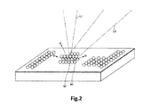
- FIG. 2 schematically shows the manner in which the melting electron beam L1 and the static electricity neutralizing electron beam L2 are emitted.
- a position Q1 on the powder is hit by the melting electron beam L1 emitted from the first electron gun 8.
- the same position Q1 is also hit by the static electricity neutralizing electron beam L2 emitted from the second electron gun 9.
- the neutralizing electron beam L2 is emitted at a tilt to the sample surface. Therefore, the diameter of the spot formed by the neutralizing electron beam L2 can be made larger than the diameter of the spot formed by the melting electron beam L1.
- FIG. 2 schematically illustrates the principal operation of the additive manufacturing machine 1.
- the sample stage 4 is placed by the drive mechanism 5 at a position that is shifted vertically downwardly from the top surface of the additive manufacturing frame 3 by ⁇ Z that is equal to the vertical thickness of the metal powder M1 subsequently spread tightly. Then, the powder feeder 7 spreads the metal powder M1 over one whole surface of the support stage 4 up to the thickness ⁇ Z.
- the melting electron beam L1 is emitted at the metal powder M1 from the first electron gun 8.
- the first electron gun 8 emits the melting beam L1 at the metal powder M1 in accordance with each two-dimensional shape of the slices obtained by slicing a previously prepared design object at intervals of ⁇ Z, the design object being represented by three-dimensional CAD (computer-aided design) data.
- CAD computer-aided design
- the second electron gun 9 emits the static electricity neutralizing electron beam L2 at the same position hit by the melting beam L1 emitted from the first electron gun 8.
- the beams L1 and L2 scan the given region of the metal powder M1 while being synchronized with each other.
- the spot of the melting beam L1 is included within the spot of the neutralizing beam L2. That is, the step of emitting the melting electron beam L1 and the step of emitting the static electricity neutralizing electron beam L2 are performed at the same time.
- FIGS. 3A-3C The advantageous effects of the static electricity neutralizing electron beam L2 are next described by referring to FIGS. 3A-3C .
- the metal powder M1 is negatively charged as described previously.
- the negatively charged grains of the metal powder M1 repel each other as shown in FIG. 5 , scattering the metal powder M1.
- the second electron gun 9 emits the static electricity neutralizing electron beam L2 at the angle ⁇ 1 to the sample surface.
- This neutralizing beam L2 penetrates into the sample surface less deeply than the melting electron beam L1 impinging normally on the sample surface.
- the beam spot formed on the sample surface is larger in diameter than where the electron beam impinges substantially normally on the sample surface. This can extend the range of the metal powder M 1 from which secondary electrons are released. Consequently, a greater number of secondary electrons than incident secondary electrons are released from the sample surface.
- the metal powder M1 is temporarily positively charged, the powder is quickly neutralized by the released secondary electrons.
- FIG. 3C A case in which the melting electron beam L1 and the static electricity neutralizing electron beam L2 hit the powder at the same position is next described by referring to FIG. 3C .
- the metal powder M1 is negatively charged by the melting electron beam L1 impinging substantially perpendicularly on the sample surface.
- secondary electrons are released from the metal powder M1 owing to the static electricity neutralizing electron beam L2 impinging obliquely on the sample surface.
- the released secondary electrons are redistributed according to the amount of static electricity on the metal powder M1. Consequently, static electricity of the negatively charged metal powder M1 can be eliminated and the metal powder M1 can be neutralized.
- the additive manufacturing machine 1 of the present embodiment can eliminate static electricity of the metal powder M1 without using an inert gas by emitting the static electricity neutralizing electron beam L2 from the second electron gun 9 while tilting the beam relative to the sample surface.
- scattering of the metal powder M1 due to negative charging of the metal powder M1 can be prevented.
- the molten metal powder M1 solidifies when a given time according to the material elapses. After one layer of metal powder M1 melts and solidifies, the support stage 4 is lowered an incremental distance of ⁇ Z by the drive mechanism 5. This motion of the stage 4 in the Z-direction is permitted by sliding motion of the seal member 14 along the inner surface of the pit 3a in the additive manufacturing frame 3.
- the metal powder M1 is again spread tightly up to a height of ⁇ Z by the powder feeder 7 on the lower layer formed immediately previously.
- a region of the metal powder M1 conforming to the two-dimensional shape corresponding to this second layer is molten and solidified by the melting electron beam L1 emitted from the first electron gun 8.
- the second electron gun 9 emits the static electricity neutralizing electron beam L2 at the powder such that the position hit by the melting beam L1 is also hit by the neutralizing beam L2.
- This series of steps is repeated to stack layers of molten and solidified metal powder M1 on top of each other, thus building the 3D object P1.
Landscapes
- Engineering & Computer Science (AREA)
- Chemical & Material Sciences (AREA)
- Materials Engineering (AREA)
- Manufacturing & Machinery (AREA)
- Physics & Mathematics (AREA)
- Mechanical Engineering (AREA)
- Health & Medical Sciences (AREA)
- General Health & Medical Sciences (AREA)
- Toxicology (AREA)
- Optics & Photonics (AREA)
- Plasma & Fusion (AREA)
- Powder Metallurgy (AREA)
Abstract
Description
- The present invention relates to a machine and method for 'additive manufacturing', fabricating a three-dimensional object by spreading a powdered material on a support stage to form a thin layer of the powdered material and stacking such layers on top of each other.
- In recent years, techniques for fabricating a three-dimensional (3D) object by spreading a powdered material to form a thin layer and stacking such layers on top of each other have attracted lots of attention, and many kinds of additive manufacturing techniques have been developed using different powdered materials and different additive manufacturing procedures (see, for example, patent document 1).
-
FIG. 4 is a schematic cross section of a related art additive manufacturing machine, 100. Theadditive manufacturing machine 100 spreads a metal powder M1 tightly on the top surface of apowder support stage 104 using apowder feeder 107 to form one layer. Then, only a two-dimensional structural portion of the metal powder M1 which has been spread tightly on thestage 104 and which corresponds to one cross section of a three-dimensional object P1 to be created is molten with an electron beam. The three-dimensional object is built by stacking such layers of the metal powder M1 on top of each other in the direction of height (in the Z-direction). - As shown in
FIG. 4 , theadditive manufacturing machine 100 has anelectron gun 108 mounted in the top of avacuum vessel 102. A cylindricaladditive manufacturing platform 103 is mounted inside thevacuum vessel 102. Anelectron beam controller 111 for controlling theelectron gun 108 is connected with theelectron gun 108. Theplatform 103 is centrally provided with apit 103a. Adrive mechanism 105 by which thestage 104 is movably supported is mounted below thepit 103a. Thesupport stage 104 has ashaft portion 104d to which thedrive mechanism 105 is coupled to drive thestage 104 in the vertical direction. The interior of thevacuum vessel 102 is maintained at a vacuum. - The
support stage 104 is placed by thedrive mechanism 105 at a position that is lower than the top surface of theadditive manufacturing platform 103 by a distance of ΔZ. The metal powder M1 is spread tightly up to a thickness equal to the distance ΔZ on thestage 104 by thepowder feeder 107. - A previously prepared, designed three-dimensional model is sliced into multiple two-dimensional shapes which are spaced from each other at intervals of ΔZ. In conformity with one of the two-dimensional shapes, an electron beam L1 is directed from the
electron gun 108 at the metal powder M1. The region of the metal powder M1 conforming to the two-dimensional shape is molten by the electron beam L1 emitted from theelectron gun 108. When a given time according to the material elapses, the molten metal powder M1 solidifies. After one layer of metal powder M1 is molten and solidifies, thesupport stage 104 is lowered an incremental distance equal to ΔZ by thedrive mechanism 105. Then, an amount of the metal powder M1 for achieving a thickness of ΔZ is spread tightly on the lower layer formed immediately previously. The region of the metal powder M1 corresponding to the two-dimensional shape corresponding to this layer is illuminated with the electron beam L1 to melt and solidify the metal powder M1. This series of steps is repeated to stack layers of the molten and solidified metal powder M1 on top of each other, thus creating a three-dimensional object. - Patent document 1:
JP-T-2010-526694 -
FIG. 3A schematically shows the state of electrons when the metal powder M1 is illuminated with the electron beam L1. However, with theadditive manufacturing machine 100 shown inFIG. 4 , when the electron beam L1 impinges substantially perpendicularly on the sample surface, most of the impinging electrons penetrate into the sample surface and diffuse into the sample layer located under the metal powder M1 spread tightly as shown inFIG. 3A . Some electrons stay in the metal powder M1. - Where the metal powder M1 is an insulator, the metal powder M1 is negatively charged by the electron beam L1. Even where the metal powder M1 is a conductor, if the grains of the powder each have a small ground contact area, are spherical in shape, and make a point contact with each other, then the powder is negatively charged in the same way as for an insulator, because the amount of current of the electron beam L1 is large. Therefore, as shown in
FIG. 5 , the negatively charged grains of the metal powder M1 repel each other. This creates the danger that the powder M1 will be scattered. - In order to prevent the metal powder M1 from being negatively charged and scattering, it is conceivable to mount a
gas introduction device 112 on thevacuum vessel 102 to introduce an inert gas F1 for neutralizing the charged metal powder M1 as shown inFIG. 4 . When the inert gas F1 is introduced, however, the energy of the electron beam L1 emitted from theelectron gun 108 is scattered and lost, thus presenting the problem that the metal powder M1 is not molten. Another problem is that the inert gas F1 adheres to theelectron gun 108, shortening the lifetime of thegun 108. - In view of the foregoing problems, it is desirable to provide a machine and method for additive manufacturing capable of eliminating static electricity of a powdered material without using an inert gas and of preventing scattering of the powdered material.
- According to the present invention, there is provided san additive manufacturing machine as set out in claim 1 and an additive manufacturing method as set out in
claim 5. - An additive manufacturing machine which solves the foregoing problems and achieves the above-described object of the invention has a support stage, a first electron gun, and a second electron gun. A powdered material for creating a three-dimensional (3D) object is spread tightly on the support stage. The first electron gun emits an electron beam at a given region of the powdered material that has been spread tightly on the support stage to melt the given region of the material. The second electron gun emits an electron beam at a sample surface formed by the powdered material spread tightly while the beam is tilted relative to the sample surface. Thus, static electricity on the powdered material is eliminated.
- An additive manufacturing method according to the present invention includes the following steps: (1) spreading a powdered material for creating a three-dimensional object tightly on one surface of a support stage; (2) illuminating a given region of the powdered material spread tightly on the support stage with an electron beam from a first electron gun to melt the given region of the powdered material; and (3) directing a second electron beam from a second electron gun different from the first electron gun at a sample surface formed by the powdered material spread tightly on the support stage while tilting the second electron beam to eliminate static electricity of the powdered material.
- According to the machine and method for additive manufacturing according to the present invention, static electricity on the powdered material can be eliminated by the second electron gun. Consequently, scattering of the powdered material due to static electricity can be prevented.
-
-
FIG. 1 is a schematic cross-sectional view of an additive manufacturing machine associated with one embodiment of the present invention. -
FIG. 2 is a fragmentary perspective view of the additive manufacturing machine shown inFIG. 1 , showing the manner in which electron beams are emitted from first and second electron guns. -
FIGS. 3A-3C are schematic cross-sectional views showing various manners in which the electron beams from the first and second electron guns shown inFIG. 2 impinge on a sample surface. -
FIG. 4 is a schematic cross-sectional view of a related art additive manufacturing machine. -
FIG. 5 is a fragmentary perspective view of the related art additive manufacturing machine shown inFIG. 4 , showing electron beam illumination. - An embodiment of the additive manufacturing machine of the present invention is hereinafter described with reference to
FIGS. 1-3 . In the various figures, like components are indicated by like reference numerals. Although the various areas of the description are provided in the following order, the invention is not restricted to the following embodiment. -
- 1-1. Configuration of Additive manufacturing Machine
- 1-2. Operation of Additive manufacturing Machine
- First, one embodiment of the additive manufacturing machine of the present invention is described by referring to
FIG. 1 , which schematically shows the machine. The additive manufacturing machine, 1, shown inFIG. 1 is used to fabricate a multilayered three-dimensional object by illuminating a powdered material consisting of a metal powder of titanium, aluminum, iron, or other metal with an electron beam to melt the powdered material and stacking layers of the solidified powdered material on top of each other. - The additive manufacturing machine 1 has a hollow vacuum vessel 2, an
additive manufacturing frame 3, a support stage 4, amechanical drive 5 by which the stage 4 is movably supported, apowder feeder 7 for supplying the metal powder M1 that is one example of powdered material onto the support stage 4, afirst electron gun 8, and asecond electron gun 9. Furthermore, the additive manufacturing machine 1 has a firstelectron beam controller 11 for controlling thefirst electron gun 8 and a secondelectron beam controller 12 for controlling thesecond electron gun 9. - A vacuum pump (not shown) is connected with the vacuum vessel 2. The interior of the vacuum vessel 2 is maintained at a vacuum by evacuating the vacuum vessel 2 using the vacuum pump. The
additive manufacturing frame 3, support stage 4,drive mechanism 5, andpowder feeder 7 are mounted in the vacuum vessel 2. - The
additive manufacturing frame 3 is disposed in a lower part of the vacuum vessel 2. Theframe 3 is provided with apit 3a extending vertically through the frame. Thepit 3a has an opening shaped like a square pole. A part of the outer periphery of thepit 3a is open to permit the completed 3D object P1 to be taken out. - The support stage 4 and drive
mechanism 5 are disposed in thepit 3a of theadditive manufacturing frame 3. The support stage 4 is shaped like a flat plate. The metal powder M1 for creating the 3D object P1 is stacked as layers on the stage 4. Aseal member 14 having heat resistance and flexibility is attached to the outer end of the stage 4. Theseal member 14 is slidably in contact with the wall surface of thepit 3a. A space formed vertically below the stage 4 and a space formed vertically above the stage 4 are hermetically closed by theseal member 14. - A
shaft 4d is mounted on the other surface of the support stage 4 which faces away from the surface on which the metal powder M1 is spread as layers. Theshaft 4d protrudes vertically downwardly from the other surface of the support stage 4. Theshaft 4d is connected with thedrive mechanism 5, which in turn drives the support stage 4 in the vertical direction via theshaft 4d. Examples of thedrive mechanism 5 include a rack and pinion and a ball screw. - The
powder feeder 7 is disposed over theadditive manufacturing frame 3. The metal powder M1 is fed out into thepowder feeder 7 from a metal powder vat (not shown) via a feeding tube. Thepowder feeder 7 has anexhaust port 7a in its bottom. The metal powder M1 is expelled from theexhaust port 7a of thepowder feeder 7 such that the powder M1 is spread tightly over one whole surface of the support stage 4. A leveling plate for leveling off the metal powder M1 supplied onto one surface of the support stage 4 may be mounted in the vacuum vessel 2. - The mechanism for supplying the metal powder M1 onto one surface of the support stage 4 is not restricted to the foregoing mechanism. For example, the metal powder M1 previously supplied in the vacuum vessel 2 may be conveyed to the support stage 4 via an arm member in the form of a flat plate and spread tightly over one surface of the stage 4.
- The
first electron gun 8 and thesecond electron gun 9 are mounted in an upper part of the vacuum vessel 2 and face one surface of the support stage 4. Thefirst electron gun 8 emits a melting electron beam L1 at a given region of the metal powder M1 spread tightly over one surface of the stage 4 to melt this region of the powder M1. Thefirst electron gun 8 is connected with a first electronbeam gun controller 11 that determines the output value of the melting electron beam L1 emitted from thefirst electron gun 8 and the position on the metal powder M1 hit by the melting electron beam L1. Thebeam controller 11 outputs information about the determined output value and position to thefirst electron gun 8 and activates thegun 8. - The
second electron gun 9 emits an electron beam L2 at the whole metal powder M1 spread tightly over one surface of the support stage 4 to neutralize static electricity on the powder, thus removing static electricity on the powder M1. Thesecond electron gun 9 is connected with the secondelectron gun controller 12, which determines the output value of the static electricity neutralizing electron beam L2 and the position on the powder hit by the second electron beam L2. The secondelectron beam controller 12 outputs information about the determined output value and position to thesecond electron gun 9 and activates thegun 9. - The
second electron gun 9 emits the static electricity neutralizing electron beam L2 while the beam is tilted at a given angle θ1 relative to a plane (hereinafter referred to as the sample surface) formed by the metal powder M1 that is spread tightly over one surface of the support stage 4. The tilt angle θ1 is set to about 45 degrees or less, for example, relative to the sample surface. The output of the neutralizing electron beam L2 from thesecond electron gun 9 is set lower than the output of the melting electron beam L1 from thefirst electron gun 8. The energy of the melting electron beam L1 and the energy of the neutralizing electron beam L2 are set, for example, to 60 kV and 1 kV, respectively. -
FIG. 2 schematically shows the manner in which the melting electron beam L1 and the static electricity neutralizing electron beam L2 are emitted. A position Q1 on the powder is hit by the melting electron beam L1 emitted from thefirst electron gun 8. The same position Q1 is also hit by the static electricity neutralizing electron beam L2 emitted from thesecond electron gun 9. The neutralizing electron beam L2 is emitted at a tilt to the sample surface. Therefore, the diameter of the spot formed by the neutralizing electron beam L2 can be made larger than the diameter of the spot formed by the melting electron beam L1. - The operation of the additive manufacturing machine 1 having the above-described configuration is next described by referring to
FIGS. 1 and2. FIG. 2 schematically illustrates the principal operation of the additive manufacturing machine 1. - First, as shown in
FIG. 1 , the sample stage 4 is placed by thedrive mechanism 5 at a position that is shifted vertically downwardly from the top surface of theadditive manufacturing frame 3 by ΔZ that is equal to the vertical thickness of the metal powder M1 subsequently spread tightly. Then, thepowder feeder 7 spreads the metal powder M1 over one whole surface of the support stage 4 up to the thickness ΔZ. - When the step of spreading the metal powder M1 tightly is complete, the melting electron beam L1 is emitted at the metal powder M1 from the
first electron gun 8. In particular, thefirst electron gun 8 emits the melting beam L1 at the metal powder M1 in accordance with each two-dimensional shape of the slices obtained by slicing a previously prepared design object at intervals of ΔZ, the design object being represented by three-dimensional CAD (computer-aided design) data. As a result, a region of the metal powder M1 corresponding to the two-dimensional shape is molten. - At this time, the
second electron gun 9 emits the static electricity neutralizing electron beam L2 at the same position hit by the melting beam L1 emitted from thefirst electron gun 8. The beams L1 and L2 scan the given region of the metal powder M1 while being synchronized with each other. The spot of the melting beam L1 is included within the spot of the neutralizing beam L2. That is, the step of emitting the melting electron beam L1 and the step of emitting the static electricity neutralizing electron beam L2 are performed at the same time. - The advantageous effects of the static electricity neutralizing electron beam L2 are next described by referring to
FIGS. 3A-3C . When the electron beam L1 impinges substantially normally on the sample surface as shown inFIG. 3A , the metal powder M1 is negatively charged as described previously. The negatively charged grains of the metal powder M1 repel each other as shown inFIG. 5 , scattering the metal powder M1. - On the other hand, as shown in
FIG. 3B , in the additive manufacturing machine 1 according to the present embodiment, thesecond electron gun 9 emits the static electricity neutralizing electron beam L2 at the angle θ1 to the sample surface. This neutralizing beam L2 penetrates into the sample surface less deeply than the melting electron beam L1 impinging normally on the sample surface. Furthermore, as described previously, the beam spot formed on the sample surface is larger in diameter than where the electron beam impinges substantially normally on the sample surface. This can extend the range of the metal powder M 1 from which secondary electrons are released. Consequently, a greater number of secondary electrons than incident secondary electrons are released from the sample surface. Although the metal powder M1 is temporarily positively charged, the powder is quickly neutralized by the released secondary electrons. - A case in which the melting electron beam L1 and the static electricity neutralizing electron beam L2 hit the powder at the same position is next described by referring to
FIG. 3C . As shown inFIG. 3C , the metal powder M1 is negatively charged by the melting electron beam L1 impinging substantially perpendicularly on the sample surface. However, secondary electrons are released from the metal powder M1 owing to the static electricity neutralizing electron beam L2 impinging obliquely on the sample surface. The released secondary electrons are redistributed according to the amount of static electricity on the metal powder M1. Consequently, static electricity of the negatively charged metal powder M1 can be eliminated and the metal powder M1 can be neutralized. - In this way, the additive manufacturing machine 1 of the present embodiment can eliminate static electricity of the metal powder M1 without using an inert gas by emitting the static electricity neutralizing electron beam L2 from the
second electron gun 9 while tilting the beam relative to the sample surface. As a result, scattering of the metal powder M1 due to negative charging of the metal powder M1 can be prevented. Furthermore, it is not necessary to introduce an inert gas into the vacuum vessel 2, thus preventing attenuation of the energy of the melting electron beam L1 emitted from thefirst electron gun 8. - The molten metal powder M1 solidifies when a given time according to the material elapses. After one layer of metal powder M1 melts and solidifies, the support stage 4 is lowered an incremental distance of ΔZ by the
drive mechanism 5. This motion of the stage 4 in the Z-direction is permitted by sliding motion of theseal member 14 along the inner surface of thepit 3a in theadditive manufacturing frame 3. - The metal powder M1 is again spread tightly up to a height of ΔZ by the
powder feeder 7 on the lower layer formed immediately previously. A region of the metal powder M1 conforming to the two-dimensional shape corresponding to this second layer is molten and solidified by the melting electron beam L1 emitted from thefirst electron gun 8. Furthermore, thesecond electron gun 9 emits the static electricity neutralizing electron beam L2 at the powder such that the position hit by the melting beam L1 is also hit by the neutralizing beam L2. This series of steps is repeated to stack layers of molten and solidified metal powder M1 on top of each other, thus building the 3D object P1. Thus, the operation of the additive manufacturing machine 1 according to the present embodiment is completed. - It is to be understood that the present invention is not restricted to the embodiment described above and shown in the accompanying drawings and that various modifications are possible without departing from the scope of the present invention as set forth in the appended claims.
Claims (5)
- An additive manufacturing machine comprising:a support stage on which a powdered material for creating a three-dimensional object is spread tightly;a first electron gun for emitting an electron beam at a given region of the powdered material spread tightly on the support stage to melt the given region of the powdered material; anda second electron gun for emitting a second electron beam at a sample surface formed by the powdered material spread tightly on the support stage while the second electron beam is tilted at a tilt angle relative to the sample surface to eliminate static electricity of the powdered material.
- An additive manufacturing machine as set forth in claim 1, wherein the electron beam emitted from said first electron gun and the electron beam emitted from said second electron gun hit the powdered material at the same position.
- An additive manufacturing machine as set forth in claim 1, wherein said tilt angle at which said second electron gun emits the electron beam at said sample surface is set to 45 degrees or less relative to the sample surface.
- An additive manufacturing machine as set forth in claim 1, wherein said electron beam emitted from said second electron gun is set lower energy than that of the electron beam emitted from said first electron gun.
- An additive manufacturing method comprising the steps of:spreading a powdered material for creating a three-dimensional object tightly on one surface of a support stage;illuminating a given region of the powdered material on the support stage with an electron beam emitted from a first electron gun to melt the given region of the powdered material; andilluminating a sample surface formed by the powdered material on the support stage with a second electron beam emitted from a second electron gun different from the first electron gun while tilting the second electron beam to eliminate static electricity of the powdered material.
Applications Claiming Priority (1)
| Application Number | Priority Date | Filing Date | Title |
|---|---|---|---|
| JP2014050677A JP2015175012A (en) | 2014-03-13 | 2014-03-13 | Three-dimensional additive manufacturing apparatus and three-dimensional additive manufacturing method |
Publications (2)
| Publication Number | Publication Date |
|---|---|
| EP2937163A1 true EP2937163A1 (en) | 2015-10-28 |
| EP2937163B1 EP2937163B1 (en) | 2017-05-03 |
Family
ID=52813890
Family Applications (1)
| Application Number | Title | Priority Date | Filing Date |
|---|---|---|---|
| EP15158338.2A Not-in-force EP2937163B1 (en) | 2014-03-13 | 2015-03-10 | Method for additive manufacturing |
Country Status (3)
| Country | Link |
|---|---|
| US (1) | US9452489B2 (en) |
| EP (1) | EP2937163B1 (en) |
| JP (1) | JP2015175012A (en) |
Cited By (8)
| Publication number | Priority date | Publication date | Assignee | Title |
|---|---|---|---|---|
| CN105750548A (en) * | 2015-10-29 | 2016-07-13 | 西安智熔金属打印系统有限公司 | Electron beam metal jet additive manufacturing apparatus and electron beam metal spray additive manufacturing method |
| CN106504966A (en) * | 2016-10-18 | 2017-03-15 | 西安智熔金属打印系统有限公司 | An integrated array electron gun and electron beam selective melting rapid prototyping system |
| EP3189961A4 (en) * | 2015-11-13 | 2018-05-16 | Technology Research Association for Future Additive Manufacturing | Three-dimensional laminate shaping device, method for controlling three-dimensional laminate shaping device, and program for controlling three-dimensional laminate shaping device |
| EP3363564A1 (en) * | 2017-02-21 | 2018-08-22 | Technische Universität München | Electrically discharging particles by increasing inter-particle conductivity |
| EP3248716A4 (en) * | 2016-03-25 | 2018-08-29 | Technology Research Association for Future Additive Manufacturing | Three-dimensional additive manufacturing device, control method for three-dimensional additive manufacturing device, and control program for three-dimensional additive manufacturing device |
| EP3488995A1 (en) * | 2017-11-24 | 2019-05-29 | CL Schutzrechtsverwaltungs GmbH | Powder module |
| WO2019185642A1 (en) | 2018-03-27 | 2019-10-03 | Freemelt Ab | Radiation method for additive manufacturing |
| WO2021003256A1 (en) * | 2019-07-02 | 2021-01-07 | Nikon Corporation | Enhanced powder bed discharging |
Families Citing this family (13)
| Publication number | Priority date | Publication date | Assignee | Title |
|---|---|---|---|---|
| KR20180061136A (en) * | 2015-06-19 | 2018-06-07 | 어플라이드 머티어리얼스, 인코포레이티드 | Selective deposition of powders in laminate manufacturing |
| CN106935461B (en) * | 2015-12-30 | 2018-11-02 | 核工业北京地质研究院 | A kind of increasing material manufacturing method based on charged particle orientated deposition in the electric field |
| WO2017163404A1 (en) * | 2016-03-25 | 2017-09-28 | 技術研究組合次世代3D積層造形技術総合開発機構 | 3d additive manufacturing device, control method for 3d additive manufacturing device, and control program for 3d additive manufacturing device |
| JP6234596B1 (en) * | 2016-05-31 | 2017-11-22 | 技術研究組合次世代3D積層造形技術総合開発機構 | Three-dimensional additive manufacturing system, three-dimensional additive manufacturing method, additive manufacturing control device, control method thereof, and control program |
| CN106424732B (en) * | 2016-12-01 | 2018-11-13 | 西安智熔金属打印系统有限公司 | A kind of electron beam fuse increasing material manufacturing device |
| KR101887620B1 (en) * | 2017-05-29 | 2018-08-10 | (주)센트롤 | Three-dimensional object |
| SI25442A (en) * | 2017-06-13 | 2018-12-31 | Mušević Nataša | Device and method for additive manufacturing of three-dimensional objects |
| JP6445113B2 (en) * | 2017-10-24 | 2018-12-26 | 技術研究組合次世代3D積層造形技術総合開発機構 | Three-dimensional additive manufacturing system, three-dimensional additive manufacturing method, additive manufacturing control device, control method thereof, and control program |
| JP6926962B2 (en) * | 2017-11-07 | 2021-08-25 | 株式会社豊田中央研究所 | Evaluation device for raw material powder for laminated molding and its evaluation jig |
| US11426818B2 (en) | 2018-08-10 | 2022-08-30 | The Research Foundation for the State University | Additive manufacturing processes and additively manufactured products |
| CN111266584B (en) * | 2020-04-14 | 2022-02-11 | 天津清研智束科技有限公司 | Additive manufacturing method |
| CN111957959A (en) * | 2020-08-11 | 2020-11-20 | 天津清研智束科技有限公司 | Electron beam additive manufacturing device and method |
| CN118700538A (en) * | 2024-07-02 | 2024-09-27 | 华中科技大学 | An integrated FDM and EBF printing device |
Citations (4)
| Publication number | Priority date | Publication date | Assignee | Title |
|---|---|---|---|---|
| DE2263777A1 (en) * | 1971-12-28 | 1973-07-05 | Ciraud Leone Isaure Marie | METHOD AND DEVICE FOR MANUFACTURING ANY ARTICLES FROM ANY MELTABLE MATERIAL |
| JP2009006509A (en) * | 2007-06-26 | 2009-01-15 | Panasonic Electric Works Co Ltd | Manufacturing method and manufacturing apparatus for three-dimensional shaped object |
| US20130055568A1 (en) * | 2010-03-11 | 2013-03-07 | Global Beam Technologies Ag | Method and device for producing a component |
| WO2013080030A1 (en) * | 2011-11-28 | 2013-06-06 | Chivel Yuri | Method for producing three-dimensional articles from powders and apparatus for carrying out said method |
Family Cites Families (5)
| Publication number | Priority date | Publication date | Assignee | Title |
|---|---|---|---|---|
| FR2087764A5 (en) * | 1970-05-29 | 1971-12-31 | Commissariat Energie Atomique | |
| EP1209737B2 (en) * | 2000-11-06 | 2014-04-30 | Hitachi, Ltd. | Method for specimen fabrication |
| JP2007018860A (en) * | 2005-07-07 | 2007-01-25 | Canon Inc | Charge reduction apparatus, exposure apparatus, measurement apparatus, and device manufacturing method |
| KR101491678B1 (en) | 2007-05-15 | 2015-02-09 | 아르켐 에이비 | Method and apparatus for manufacturing a three-dimensional object |
| US9279058B2 (en) * | 2013-01-11 | 2016-03-08 | Floor Iptech Ab | Digital embossing |
-
2014
- 2014-03-13 JP JP2014050677A patent/JP2015175012A/en active Pending
-
2015
- 2015-03-10 EP EP15158338.2A patent/EP2937163B1/en not_active Not-in-force
- 2015-03-11 US US14/644,278 patent/US9452489B2/en not_active Expired - Fee Related
Patent Citations (4)
| Publication number | Priority date | Publication date | Assignee | Title |
|---|---|---|---|---|
| DE2263777A1 (en) * | 1971-12-28 | 1973-07-05 | Ciraud Leone Isaure Marie | METHOD AND DEVICE FOR MANUFACTURING ANY ARTICLES FROM ANY MELTABLE MATERIAL |
| JP2009006509A (en) * | 2007-06-26 | 2009-01-15 | Panasonic Electric Works Co Ltd | Manufacturing method and manufacturing apparatus for three-dimensional shaped object |
| US20130055568A1 (en) * | 2010-03-11 | 2013-03-07 | Global Beam Technologies Ag | Method and device for producing a component |
| WO2013080030A1 (en) * | 2011-11-28 | 2013-06-06 | Chivel Yuri | Method for producing three-dimensional articles from powders and apparatus for carrying out said method |
Cited By (12)
| Publication number | Priority date | Publication date | Assignee | Title |
|---|---|---|---|---|
| CN105750548A (en) * | 2015-10-29 | 2016-07-13 | 西安智熔金属打印系统有限公司 | Electron beam metal jet additive manufacturing apparatus and electron beam metal spray additive manufacturing method |
| EP3189961A4 (en) * | 2015-11-13 | 2018-05-16 | Technology Research Association for Future Additive Manufacturing | Three-dimensional laminate shaping device, method for controlling three-dimensional laminate shaping device, and program for controlling three-dimensional laminate shaping device |
| US10500834B2 (en) | 2015-11-13 | 2019-12-10 | Technology Research Association For Future Additive Manufacturing | Three-dimensional laminating and shaping apparatus, control method of three-dimensional laminating and shaping apparatus, and control program of three-dimensional laminating and shaping apparatus |
| EP3248716A4 (en) * | 2016-03-25 | 2018-08-29 | Technology Research Association for Future Additive Manufacturing | Three-dimensional additive manufacturing device, control method for three-dimensional additive manufacturing device, and control program for three-dimensional additive manufacturing device |
| US10610957B2 (en) | 2016-03-25 | 2020-04-07 | Technology Research Association For Future Additive Manufacturing | Three-dimensional laminating and shaping apparatus, three-dimensional laminating and shaping apparatus control method, and three-dimensional laminating and shaping apparatus control program |
| CN106504966A (en) * | 2016-10-18 | 2017-03-15 | 西安智熔金属打印系统有限公司 | An integrated array electron gun and electron beam selective melting rapid prototyping system |
| CN106504966B (en) * | 2016-10-18 | 2018-05-22 | 西安智熔金属打印系统有限公司 | A kind of integration array electronic rifle and electron beam selective melting rapid forming system |
| EP3363564A1 (en) * | 2017-02-21 | 2018-08-22 | Technische Universität München | Electrically discharging particles by increasing inter-particle conductivity |
| EP3488995A1 (en) * | 2017-11-24 | 2019-05-29 | CL Schutzrechtsverwaltungs GmbH | Powder module |
| US11141917B2 (en) | 2017-11-24 | 2021-10-12 | Concept Laser Gmbh | Powder module |
| WO2019185642A1 (en) | 2018-03-27 | 2019-10-03 | Freemelt Ab | Radiation method for additive manufacturing |
| WO2021003256A1 (en) * | 2019-07-02 | 2021-01-07 | Nikon Corporation | Enhanced powder bed discharging |
Also Published As
| Publication number | Publication date |
|---|---|
| EP2937163B1 (en) | 2017-05-03 |
| JP2015175012A (en) | 2015-10-05 |
| US20150306700A1 (en) | 2015-10-29 |
| US9452489B2 (en) | 2016-09-27 |
Similar Documents
| Publication | Publication Date | Title |
|---|---|---|
| US9452489B2 (en) | Machine and method for additive manufacturing | |
| JP6273578B2 (en) | Three-dimensional additive manufacturing apparatus and three-dimensional additive manufacturing method | |
| JP5135594B2 (en) | Method for making 3D objects | |
| US10029417B2 (en) | Articulating build platform for laser additive manufacturing | |
| JP6231695B1 (en) | Control method for three-dimensional additive manufacturing apparatus, control method for three-dimensional additive manufacturing apparatus, and control program for three-dimensional additive manufacturing apparatus | |
| JP6919714B2 (en) | 3D modeling device and 3D modeling method | |
| US20200061915A1 (en) | Interchangeable chamber for a device and a method for the additive manufacturing of a three-dimensional object | |
| EP3789140A1 (en) | Three-dimensional additive manufacturing device and method with detection of powder bed abnormalities | |
| US20160311024A1 (en) | Method and Device for Producing a Three-Dimensional Object | |
| US10610957B2 (en) | Three-dimensional laminating and shaping apparatus, three-dimensional laminating and shaping apparatus control method, and three-dimensional laminating and shaping apparatus control program | |
| JP6866931B2 (en) | 3D modeling device and 3D modeling method | |
| US11110518B2 (en) | Method and apparatus for manufacturing a three-dimensional object | |
| US11554442B2 (en) | Additive manufacturing device and additive manufacturing method | |
| US20210213536A1 (en) | Method for preparing the upper surface of an additive manufactuirng platen by depositing a bed of powder | |
| US20160008886A1 (en) | Devices, systems and methods for producing a 3d printed product | |
| JP6283539B2 (en) | Three-dimensional additive manufacturing apparatus and three-dimensional additive manufacturing method | |
| JP7276007B2 (en) | Three-dimensional modeling method | |
| RU164759U1 (en) | DEVICE WORK CAMERA FOR PRODUCTION OF PARTS BY LAYERED LASER SINTERING | |
| EP4253008A1 (en) | Three-dimensional modeling device and three-dimensional modeling method | |
| KR102056825B1 (en) | Preheating and sintering processes of the metallic powder using a plasma electron beam | |
| US10252334B1 (en) | Laser sintering system and method |
Legal Events
| Date | Code | Title | Description |
|---|---|---|---|
| PUAI | Public reference made under article 153(3) epc to a published international application that has entered the european phase |
Free format text: ORIGINAL CODE: 0009012 |
|
| AK | Designated contracting states |
Kind code of ref document: A1 Designated state(s): AL AT BE BG CH CY CZ DE DK EE ES FI FR GB GR HR HU IE IS IT LI LT LU LV MC MK MT NL NO PL PT RO RS SE SI SK SM TR |
|
| AX | Request for extension of the european patent |
Extension state: BA ME |
|
| 17P | Request for examination filed |
Effective date: 20160426 |
|
| RBV | Designated contracting states (corrected) |
Designated state(s): AL AT BE BG CH CY CZ DE DK EE ES FI FR GB GR HR HU IE IS IT LI LT LU LV MC MK MT NL NO PL PT RO RS SE SI SK SM TR |
|
| GRAP | Despatch of communication of intention to grant a patent |
Free format text: ORIGINAL CODE: EPIDOSNIGR1 |
|
| RIC1 | Information provided on ipc code assigned before grant |
Ipc: B29C 67/00 20060101ALI20161102BHEP Ipc: B22F 3/105 20060101AFI20161102BHEP |
|
| INTG | Intention to grant announced |
Effective date: 20161128 |
|
| GRAS | Grant fee paid |
Free format text: ORIGINAL CODE: EPIDOSNIGR3 |
|
| GRAA | (expected) grant |
Free format text: ORIGINAL CODE: 0009210 |
|
| AK | Designated contracting states |
Kind code of ref document: B1 Designated state(s): AL AT BE BG CH CY CZ DE DK EE ES FI FR GB GR HR HU IE IS IT LI LT LU LV MC MK MT NL NO PL PT RO RS SE SI SK SM TR |
|
| REG | Reference to a national code |
Ref country code: GB Ref legal event code: FG4D |
|
| REG | Reference to a national code |
Ref country code: AT Ref legal event code: REF Ref document number: 889421 Country of ref document: AT Kind code of ref document: T Effective date: 20170515 Ref country code: CH Ref legal event code: EP |
|
| REG | Reference to a national code |
Ref country code: IE Ref legal event code: FG4D |
|
| REG | Reference to a national code |
Ref country code: DE Ref legal event code: R096 Ref document number: 602015002472 Country of ref document: DE |
|
| REG | Reference to a national code |
Ref country code: NL Ref legal event code: MP Effective date: 20170503 |
|
| REG | Reference to a national code |
Ref country code: AT Ref legal event code: MK05 Ref document number: 889421 Country of ref document: AT Kind code of ref document: T Effective date: 20170503 |
|
| REG | Reference to a national code |
Ref country code: LT Ref legal event code: MG4D |
|
| PG25 | Lapsed in a contracting state [announced via postgrant information from national office to epo] |
Ref country code: HR Free format text: LAPSE BECAUSE OF FAILURE TO SUBMIT A TRANSLATION OF THE DESCRIPTION OR TO PAY THE FEE WITHIN THE PRESCRIBED TIME-LIMIT Effective date: 20170503 Ref country code: LT Free format text: LAPSE BECAUSE OF FAILURE TO SUBMIT A TRANSLATION OF THE DESCRIPTION OR TO PAY THE FEE WITHIN THE PRESCRIBED TIME-LIMIT Effective date: 20170503 Ref country code: ES Free format text: LAPSE BECAUSE OF FAILURE TO SUBMIT A TRANSLATION OF THE DESCRIPTION OR TO PAY THE FEE WITHIN THE PRESCRIBED TIME-LIMIT Effective date: 20170503 Ref country code: AT Free format text: LAPSE BECAUSE OF FAILURE TO SUBMIT A TRANSLATION OF THE DESCRIPTION OR TO PAY THE FEE WITHIN THE PRESCRIBED TIME-LIMIT Effective date: 20170503 Ref country code: FI Free format text: LAPSE BECAUSE OF FAILURE TO SUBMIT A TRANSLATION OF THE DESCRIPTION OR TO PAY THE FEE WITHIN THE PRESCRIBED TIME-LIMIT Effective date: 20170503 Ref country code: NO Free format text: LAPSE BECAUSE OF FAILURE TO SUBMIT A TRANSLATION OF THE DESCRIPTION OR TO PAY THE FEE WITHIN THE PRESCRIBED TIME-LIMIT Effective date: 20170803 Ref country code: GR Free format text: LAPSE BECAUSE OF FAILURE TO SUBMIT A TRANSLATION OF THE DESCRIPTION OR TO PAY THE FEE WITHIN THE PRESCRIBED TIME-LIMIT Effective date: 20170804 |
|
| PG25 | Lapsed in a contracting state [announced via postgrant information from national office to epo] |
Ref country code: SE Free format text: LAPSE BECAUSE OF FAILURE TO SUBMIT A TRANSLATION OF THE DESCRIPTION OR TO PAY THE FEE WITHIN THE PRESCRIBED TIME-LIMIT Effective date: 20170503 Ref country code: LV Free format text: LAPSE BECAUSE OF FAILURE TO SUBMIT A TRANSLATION OF THE DESCRIPTION OR TO PAY THE FEE WITHIN THE PRESCRIBED TIME-LIMIT Effective date: 20170503 Ref country code: IS Free format text: LAPSE BECAUSE OF FAILURE TO SUBMIT A TRANSLATION OF THE DESCRIPTION OR TO PAY THE FEE WITHIN THE PRESCRIBED TIME-LIMIT Effective date: 20170903 Ref country code: NL Free format text: LAPSE BECAUSE OF FAILURE TO SUBMIT A TRANSLATION OF THE DESCRIPTION OR TO PAY THE FEE WITHIN THE PRESCRIBED TIME-LIMIT Effective date: 20170503 Ref country code: PL Free format text: LAPSE BECAUSE OF FAILURE TO SUBMIT A TRANSLATION OF THE DESCRIPTION OR TO PAY THE FEE WITHIN THE PRESCRIBED TIME-LIMIT Effective date: 20170503 Ref country code: RS Free format text: LAPSE BECAUSE OF FAILURE TO SUBMIT A TRANSLATION OF THE DESCRIPTION OR TO PAY THE FEE WITHIN THE PRESCRIBED TIME-LIMIT Effective date: 20170503 Ref country code: BG Free format text: LAPSE BECAUSE OF FAILURE TO SUBMIT A TRANSLATION OF THE DESCRIPTION OR TO PAY THE FEE WITHIN THE PRESCRIBED TIME-LIMIT Effective date: 20170803 |
|
| PG25 | Lapsed in a contracting state [announced via postgrant information from national office to epo] |
Ref country code: SK Free format text: LAPSE BECAUSE OF FAILURE TO SUBMIT A TRANSLATION OF THE DESCRIPTION OR TO PAY THE FEE WITHIN THE PRESCRIBED TIME-LIMIT Effective date: 20170503 Ref country code: CZ Free format text: LAPSE BECAUSE OF FAILURE TO SUBMIT A TRANSLATION OF THE DESCRIPTION OR TO PAY THE FEE WITHIN THE PRESCRIBED TIME-LIMIT Effective date: 20170503 Ref country code: RO Free format text: LAPSE BECAUSE OF FAILURE TO SUBMIT A TRANSLATION OF THE DESCRIPTION OR TO PAY THE FEE WITHIN THE PRESCRIBED TIME-LIMIT Effective date: 20170503 Ref country code: DK Free format text: LAPSE BECAUSE OF FAILURE TO SUBMIT A TRANSLATION OF THE DESCRIPTION OR TO PAY THE FEE WITHIN THE PRESCRIBED TIME-LIMIT Effective date: 20170503 Ref country code: EE Free format text: LAPSE BECAUSE OF FAILURE TO SUBMIT A TRANSLATION OF THE DESCRIPTION OR TO PAY THE FEE WITHIN THE PRESCRIBED TIME-LIMIT Effective date: 20170503 |
|
| REG | Reference to a national code |
Ref country code: DE Ref legal event code: R097 Ref document number: 602015002472 Country of ref document: DE |
|
| PG25 | Lapsed in a contracting state [announced via postgrant information from national office to epo] |
Ref country code: SM Free format text: LAPSE BECAUSE OF FAILURE TO SUBMIT A TRANSLATION OF THE DESCRIPTION OR TO PAY THE FEE WITHIN THE PRESCRIBED TIME-LIMIT Effective date: 20170503 |
|
| PLBE | No opposition filed within time limit |
Free format text: ORIGINAL CODE: 0009261 |
|
| STAA | Information on the status of an ep patent application or granted ep patent |
Free format text: STATUS: NO OPPOSITION FILED WITHIN TIME LIMIT |
|
| REG | Reference to a national code |
Ref country code: FR Ref legal event code: PLFP Year of fee payment: 4 |
|
| 26N | No opposition filed |
Effective date: 20180206 |
|
| PG25 | Lapsed in a contracting state [announced via postgrant information from national office to epo] |
Ref country code: SI Free format text: LAPSE BECAUSE OF FAILURE TO SUBMIT A TRANSLATION OF THE DESCRIPTION OR TO PAY THE FEE WITHIN THE PRESCRIBED TIME-LIMIT Effective date: 20170503 |
|
| REG | Reference to a national code |
Ref country code: CH Ref legal event code: PL |
|
| PG25 | Lapsed in a contracting state [announced via postgrant information from national office to epo] |
Ref country code: MC Free format text: LAPSE BECAUSE OF FAILURE TO SUBMIT A TRANSLATION OF THE DESCRIPTION OR TO PAY THE FEE WITHIN THE PRESCRIBED TIME-LIMIT Effective date: 20170503 |
|
| REG | Reference to a national code |
Ref country code: BE Ref legal event code: MM Effective date: 20180331 |
|
| REG | Reference to a national code |
Ref country code: IE Ref legal event code: MM4A |
|
| PG25 | Lapsed in a contracting state [announced via postgrant information from national office to epo] |
Ref country code: LU Free format text: LAPSE BECAUSE OF NON-PAYMENT OF DUE FEES Effective date: 20180310 |
|
| PG25 | Lapsed in a contracting state [announced via postgrant information from national office to epo] |
Ref country code: IE Free format text: LAPSE BECAUSE OF NON-PAYMENT OF DUE FEES Effective date: 20180310 |
|
| PG25 | Lapsed in a contracting state [announced via postgrant information from national office to epo] |
Ref country code: CH Free format text: LAPSE BECAUSE OF NON-PAYMENT OF DUE FEES Effective date: 20180331 Ref country code: BE Free format text: LAPSE BECAUSE OF NON-PAYMENT OF DUE FEES Effective date: 20180331 Ref country code: LI Free format text: LAPSE BECAUSE OF NON-PAYMENT OF DUE FEES Effective date: 20180331 |
|
| PGFP | Annual fee paid to national office [announced via postgrant information from national office to epo] |
Ref country code: DE Payment date: 20190321 Year of fee payment: 5 Ref country code: GB Payment date: 20190320 Year of fee payment: 5 Ref country code: FR Payment date: 20190322 Year of fee payment: 5 Ref country code: IT Payment date: 20190325 Year of fee payment: 5 |
|
| PG25 | Lapsed in a contracting state [announced via postgrant information from national office to epo] |
Ref country code: MT Free format text: LAPSE BECAUSE OF NON-PAYMENT OF DUE FEES Effective date: 20180310 |
|
| PG25 | Lapsed in a contracting state [announced via postgrant information from national office to epo] |
Ref country code: TR Free format text: LAPSE BECAUSE OF FAILURE TO SUBMIT A TRANSLATION OF THE DESCRIPTION OR TO PAY THE FEE WITHIN THE PRESCRIBED TIME-LIMIT Effective date: 20170503 |
|
| PG25 | Lapsed in a contracting state [announced via postgrant information from national office to epo] |
Ref country code: PT Free format text: LAPSE BECAUSE OF FAILURE TO SUBMIT A TRANSLATION OF THE DESCRIPTION OR TO PAY THE FEE WITHIN THE PRESCRIBED TIME-LIMIT Effective date: 20170503 |
|
| PG25 | Lapsed in a contracting state [announced via postgrant information from national office to epo] |
Ref country code: CY Free format text: LAPSE BECAUSE OF FAILURE TO SUBMIT A TRANSLATION OF THE DESCRIPTION OR TO PAY THE FEE WITHIN THE PRESCRIBED TIME-LIMIT Effective date: 20170503 Ref country code: HU Free format text: LAPSE BECAUSE OF FAILURE TO SUBMIT A TRANSLATION OF THE DESCRIPTION OR TO PAY THE FEE WITHIN THE PRESCRIBED TIME-LIMIT; INVALID AB INITIO Effective date: 20150310 Ref country code: MK Free format text: LAPSE BECAUSE OF NON-PAYMENT OF DUE FEES Effective date: 20170503 |
|
| PG25 | Lapsed in a contracting state [announced via postgrant information from national office to epo] |
Ref country code: AL Free format text: LAPSE BECAUSE OF FAILURE TO SUBMIT A TRANSLATION OF THE DESCRIPTION OR TO PAY THE FEE WITHIN THE PRESCRIBED TIME-LIMIT Effective date: 20170503 |
|
| REG | Reference to a national code |
Ref country code: DE Ref legal event code: R119 Ref document number: 602015002472 Country of ref document: DE |
|
| PG25 | Lapsed in a contracting state [announced via postgrant information from national office to epo] |
Ref country code: DE Free format text: LAPSE BECAUSE OF NON-PAYMENT OF DUE FEES Effective date: 20201001 Ref country code: FR Free format text: LAPSE BECAUSE OF NON-PAYMENT OF DUE FEES Effective date: 20200331 |
|
| GBPC | Gb: european patent ceased through non-payment of renewal fee |
Effective date: 20200310 |
|
| PG25 | Lapsed in a contracting state [announced via postgrant information from national office to epo] |
Ref country code: GB Free format text: LAPSE BECAUSE OF NON-PAYMENT OF DUE FEES Effective date: 20200310 |
|
| PG25 | Lapsed in a contracting state [announced via postgrant information from national office to epo] |
Ref country code: IT Free format text: LAPSE BECAUSE OF NON-PAYMENT OF DUE FEES Effective date: 20200310 |