EP2936663B1 - Elektrische maschine - Google Patents
Elektrische maschine Download PDFInfo
- Publication number
- EP2936663B1 EP2936663B1 EP13811494.7A EP13811494A EP2936663B1 EP 2936663 B1 EP2936663 B1 EP 2936663B1 EP 13811494 A EP13811494 A EP 13811494A EP 2936663 B1 EP2936663 B1 EP 2936663B1
- Authority
- EP
- European Patent Office
- Prior art keywords
- pole
- axial length
- ratio
- stator core
- rotor
- Prior art date
- Legal status (The legal status is an assumption and is not a legal conclusion. Google has not performed a legal analysis and makes no representation as to the accuracy of the status listed.)
- Not-in-force
Links
Images


Classifications
-
- H—ELECTRICITY
- H02—GENERATION; CONVERSION OR DISTRIBUTION OF ELECTRIC POWER
- H02K—DYNAMO-ELECTRIC MACHINES
- H02K9/00—Arrangements for cooling or ventilating
- H02K9/02—Arrangements for cooling or ventilating by ambient air flowing through the machine
- H02K9/04—Arrangements for cooling or ventilating by ambient air flowing through the machine having means for generating a flow of cooling medium
- H02K9/06—Arrangements for cooling or ventilating by ambient air flowing through the machine having means for generating a flow of cooling medium with fans or impellers driven by the machine shaft
-
- H—ELECTRICITY
- H02—GENERATION; CONVERSION OR DISTRIBUTION OF ELECTRIC POWER
- H02K—DYNAMO-ELECTRIC MACHINES
- H02K21/00—Synchronous motors having permanent magnets; Synchronous generators having permanent magnets
- H02K21/02—Details
- H02K21/04—Windings on magnets for additional excitation ; Windings and magnets for additional excitation
- H02K21/042—Windings on magnets for additional excitation ; Windings and magnets for additional excitation with permanent magnets and field winding both rotating
- H02K21/044—Rotor of the claw pole type
-
- H—ELECTRICITY
- H02—GENERATION; CONVERSION OR DISTRIBUTION OF ELECTRIC POWER
- H02K—DYNAMO-ELECTRIC MACHINES
- H02K1/00—Details of the magnetic circuit
- H02K1/06—Details of the magnetic circuit characterised by the shape, form or construction
- H02K1/22—Rotating parts of the magnetic circuit
- H02K1/24—Rotor cores with salient poles ; Variable reluctance rotors
- H02K1/243—Rotor cores with salient poles ; Variable reluctance rotors of the claw-pole type
-
- H—ELECTRICITY
- H02—GENERATION; CONVERSION OR DISTRIBUTION OF ELECTRIC POWER
- H02K—DYNAMO-ELECTRIC MACHINES
- H02K1/00—Details of the magnetic circuit
- H02K1/06—Details of the magnetic circuit characterised by the shape, form or construction
- H02K1/22—Rotating parts of the magnetic circuit
- H02K1/27—Rotor cores with permanent magnets
- H02K1/2706—Inner rotors
-
- H—ELECTRICITY
- H02—GENERATION; CONVERSION OR DISTRIBUTION OF ELECTRIC POWER
- H02K—DYNAMO-ELECTRIC MACHINES
- H02K3/00—Details of windings
- H02K3/04—Windings characterised by the conductor shape, form or construction, e.g. with bar conductors
- H02K3/12—Windings characterised by the conductor shape, form or construction, e.g. with bar conductors arranged in slots
-
- H—ELECTRICITY
- H02—GENERATION; CONVERSION OR DISTRIBUTION OF ELECTRIC POWER
- H02K—DYNAMO-ELECTRIC MACHINES
- H02K3/00—Details of windings
- H02K3/46—Fastening of windings on the stator or rotor structure
- H02K3/50—Fastening of winding heads, equalising connectors, or connections thereto
-
- H—ELECTRICITY
- H02—GENERATION; CONVERSION OR DISTRIBUTION OF ELECTRIC POWER
- H02K—DYNAMO-ELECTRIC MACHINES
- H02K2213/00—Specific aspects, not otherwise provided for and not covered by codes H02K2201/00 - H02K2211/00
- H02K2213/03—Machines characterised by numerical values, ranges, mathematical expressions or similar information
Definitions
- an electric machine which is designed as a so-called Klauenpolgenerator.
- This electrical machine has a stator and a rotor, wherein adjacently arranged on the circumference of the rotor, differently polarized exciter poles or claw poles generate a stator voltage in a stator winding of the stator during rotational movement.
- the excitation poles of this machine are designed as so-called claw poles.
- the object of the invention is to achieve a significant reduction in the copper mass of an electrical machine. Maintaining the efficiency and power output reduces both the weight of the field winding and the weight of the stator winding. In addition, the power density can be increased significantly.
- FIG. 1 is a cross section through an electric machine 10, shown here in the embodiment as a generator or alternator, in particular three-phase alternator for motor vehicles.
- This machine could work with a corresponding control but also as a starter generator.
- This electrical machine 10 has, inter alia, a two-part housing 13, which comprises a first end shield 13.1 and a second end shield 13.2.
- the bearing plate 13.1 and the bearing plate 13.2 take in a so-called stator 16, which comprises a substantially annular stator iron 17, in which radially inwardly directed, axially extending grooves, a stator winding 18 is inserted.
- This annular stator 16 surrounds with its radially inwardly directed grooved surface, which is an electromagnetically effective surface 19, a rotor 20 which is formed here, for example, as a claw poller.
- the rotor 20 includes u. a. two pole plates 22 and 23, on the outer periphery of each extending in the axial direction Klauenpolfinger are arranged as electromagnetically poleable claw poles 24 and 25. Both Polplatinen 22 and 23 are arranged in the rotor 20 such that their axially extending claw poles 24 and 25 on the circumference of the rotor 20 alternate with each other. Accordingly, the rotor 20 also has an electromagnetically active surface 26. Magnetically required interspaces 21, which are also referred to herein as claw pole interspaces, are produced by the claw poles 24 and 25, which alternate at the circumference.
- the rotor 20 is rotatably supported in the respective end shields 13.1 and 13.2, respectively, by means of a shaft 27 and one respective rolling bearing 28 located on each side of the rotor.
- the rotor 20 has a total of two axial end faces, on each of which a fan 30 is attached.
- This fan 30 consists essentially of a plate-shaped or disc-shaped portion, emanating from the fan blades in a known manner.
- These fans 30 serve, via openings 40 in the end shields 13.1 and 13.2, to allow an exchange of air, for example, from an axial end face of the electric machine 10 through the interior of the electric machine 10 to a radially outer environment.
- the openings 40 are provided essentially at the axial ends of the end shields 13.1 and 13.2, via which cooling air is sucked into the interior of the electric machine 10 by means of the fan 30.
- This cooling air is accelerated radially outward by the rotation of the fans 30, so that they are substantially transparent to the cooling air annular winding head 45 can pass. By this effect, the winding head 45 is cooled.
- the cooling air takes after passing through the winding overhang or winding head 45 or after flowing around this winding head 45 through here in this FIG. 1 not shown openings a way radially outward.
- this protective cap 47 protects various components against environmental influences.
- this protective cap 47 covers, for example, a so-called slip ring assembly 49, which serves to supply a field winding 51 with exciter current.
- a heat sink 53 Around this slip ring assembly 49 around a heat sink 53 is arranged, which acts as a positive heat sink here.
- This plus heat sink is called a plus heat sink because it is electrically conductively connected to a positive pole of a rechargeable battery (eg starter power supply).
- a so-called minus heat sink the bearing plate acts 13.2.
- connection plate 56 which serves to connect arranged in the bearing plate 13.2 minus diodes 58 and not shown here in this illustration plus diodes in the heat sink 53 together and thus represent a known bridge circuit.
- an electric machine 10 with a stator 16 which has a stator iron 17, disclosed.
- the stator iron 17 has a substantially cylindrical opening 60 with a central axis 63, see also FIG. 2 , The opening 60 receives the rotor 20.
- the stator iron 17 has an axial length L17a and the stator iron 17 holds the stator winding 18.
- the stator iron 17 has an inner diameter D17i and an outer diameter D17a.
- the rotor 20 has a rotation axis 66 which coincides with the central axis 63 in the mounted state.
- the rotor 20 has an axial end face 69, on which a fan 30 with fan blades 72 is arranged.
- the fan is rotatably connected to the rotor 20 - preferably directly - connected.
- the rotor 20 has an electromagnetically excitable path 75, which has a pole core 78, to each of which a pole plate 22, 23 connects to both axial ends 80, 82.
- a pole plate 22 From a pole plate 22 go claw poles 24, the one Have north polarity and from the other pole plate 23 go claw poles 25, which have a south polarity, with the claw poles 24 and 25 alternate at the periphery of the rotor 20 to north polarity and south polarity.
- the pole core 78 arranged radially inside the claw poles 24, 25 has a rotational axial length L78.
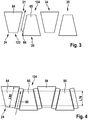
- FIG. 3 is a schematic view of a developed outer periphery of the rotor 20 can be seen.
- the trapezoidal surfaces 84 and 85 of the claw poles 24 and 25 can be seen, which conduct the electromagnetic flux above it as an interface of the rotor 20 to the interfaces on teeth of the stator 16 and from there.
- the rotor 20 has an already mentioned, a longitudinal direction 86 having gap 21 between two adjacent opposite pole claw poles 24, 25.
- the longitudinal direction 86 coincides with a center line between the claw poles 24 and 25. If the gap is bounded, for example, by mutually parallel side surfaces of the claw poles 24 and 25, then the center line runs in the middle between the side surfaces of the claw poles 24 and 25.
- a permanent magnet device 88 is used in the one gap 21 between the two claw poles 24, 25 .
- the permanent magnet device 88 has a length L88 in the longitudinal direction 86 of the gap 21 (excluding magnetically non-active portions such as holding elements).
- the permanent magnetic device 88 is used to compensate for an electromagnetic or magnetic leakage flux between a claw pole 24 with north polarity and a claw pole 25 with south polarity. It is envisaged that a ratio of the length L88 of the permanent magnet device 88 and the rotational axial length L78 of the pole core is greater than 1.3. That is, tips 123 and 124 of the claw poles 24 and 25 protrude into spaces 89 and 91 of common pole claw poles 130 and 131, respectively.
- a tip 123 of a north pole claw pole 124 protrudes between two claw pole roots 131 of two south pole claw poles 125.
- a claw pole root is here limited to the volume region which adjoins in the axial direction a cantilevered part of a claw pole 124, 125.
- a corresponding diagram shows the FIG. 4A , which was simulated taking into account permanent magnets.
- the relationship of L88 / L78 shows the course of the generated current IG at full load and a rotational speed of the rotor of 1800 / min
- this diagram shows the course of the induced voltage Ui at idle and a Excitation current IE of zero ampere in the stator winding 18 at 18000 / min.
- the desired minimum ratio of L88 / L78 of 1.3 is due to the inflection point of the course of the induced voltage Ui.
- the desired preferred ratio of L88 / L78 of greater than 1.6 is due to the onset of sharp drop in the course of the induced voltage Ui.
- a ratio of the length L88 of the permanent magnet device 88 and the rotational axial length L78 of the pole core 78 is greater than 1.6.
- the stator winding 18 has a winding head 45 which has a wire connection 93 which is guided away from the stator iron 17 over a rotational axial length L93 and back to it. If the considered wire connection 93 is the most overhanging wire connection 93, FIG. 5 , this is at the same time the rotational axial length of the winding head L45.
- the fan 30 is arranged radially inside the winding head 45, Fig. 1 and Fig. 5 , The area covered by the winding head 45 and the fan 30 together in navaxialer region over the length L45a while a share of the fan 30 navaxial covered length L93 of the wire connection 93 should be greater than 0.5, preferably greater than 0.7.
- the ratio of L45a to L45 or L45a to L93 should therefore be greater than 0.5, preferably greater than 0.7.
- the stator winding 18 is inserted into radially inwardly open grooves 96 of the stator iron, FIG. 6 ,
- an electromagnetically effective surface 100 of the groove 96 is defined.
- the surface 100 is bounded by the teeth 103 and the groove bottom 106 in the direction of the yoke 109.
- a surface 110 in the slot groove 112 between the two tooth heads 115 is disregarded, since in this construction, this space is not provided for the arrangement of a winding.
- a phase or strand winding comprises.
- the winding arrangement 117 has at least one wire cross-section 120 with an electrically effective wire cross-sectional area A120, wherein a ratio from the at least one wire cross-sectional area A120 and thus all wire cross-sections 120 in a groove 96 and the electromagnetically active surface 100 is less than 0.5.
- the FIG. 7 shows a diagram in which on the x-axis, the calculated, indicated for different variants of D17i and D17a ratio (D17i / D17a).
- the pole core 78 has a diameter D78 and a rotational axial length L78.
- the right labeled y-axis of the FIG. 7 indicates the ratio of L78 and D78 assumed for many variants.
- various ratios have been found to be favorable:
- a ratio of the axial length L78 of the pole core 78 and the diameter D78 of the pole core 78 should be between 0.21 and 0.36, preferably between 0.225 and 0.348 and particularly preferably between 0 , 25 and 0.33.
- the ratio of the inner diameter D17i of the stator iron 17 and the outer diameter D17a of the stator iron 17 should be greater than 0.788 and less than 0.854, preferably greater than 0.795 and less than 0.848, and more preferably between 0.802 and 0.841 FIG. 7 , which was simulated without consideration of permanent magnets.
- the electromagnetic path 75 between two mutually remote sides 69, 90 of the pole plates 22, 23 has the navaxiale length L75, wherein the ratio of the axial length L17a of the stator iron 17 and the rotational axial length L75 of the electromagnetic path 75 of the rotor 20 is between 0.68 and 1.0, preferably between 0.70 and 0.95, FIG. 8 , This figure was simulated without considering permanent magnets. There, the ratio of an output current IGL and a maximum output current IGL, max at 1800 1 / min is plotted against the ratio of the length L17a of the stator iron 17 and the rotational axial length L75 of the electromagnetic path 75.
- a ratio of the diameter D17i and the rotational axial length L78 of the pole core 78 is greater than 5.0.
- FIG. 9 the stator iron 17 is shown in a further enlarged end view.
- the stator iron 17 holds - as already mentioned - the stator winding 18, which is received in radially inwardly open grooves 96.
- Each groove 96 is bounded in both circumferential directions by a respective tooth 103, wherein the teeth 103 in Circumferential direction have a minimum tooth width B103 and in the radial direction have a tooth height H103.
- For the ratio of the tooth height H103 and a minimum tooth width B103 should apply a range of 0.45 to 1.02.
- a range of 0.53 to 0.96 applies, FIG. 10 , This figure was simulated without considering permanent magnets.
- a ratio of the axial length L17a of the stator iron 17 and the rotational axial length L78 of the pole core 78 is greater than 1.8 and less than 2.68, preferably greater than 1, 9 and less than 2.42, FIG. 11 , This figure was simulated without considering permanent magnets.
- the pole core 78 can be defined in various ways: The in FIG. 1 shown variant is a ring-cylindrical pole core 78 which is pushed onto the shaft 27 and is separated from the pole plates 22, 23. Another known construction provides a pole core 78, which is made of two corresponding approaches, of which one is integrally formed on the pole plates 22, 23. By sliding on the shaft 27, wherein the two approaches are facing each other, an equivalent pole core 78 is generated.
- the Polkernate L78 here is the sum of the lubaxialen lengths of the approaches
- the number of wire cross sections 120 per groove is exactly four.
- the interstices 21 should, if possible, be completely filled or filled with one or more permanent magnets as part of the permanent magnetic device 88.
- the one or more permanent magnets should be arranged centrally in the rotational axial direction between the tips 123 and 124 of the claw poles 24 and 25.
- the example in FIG. 1 visible side surfaces 127 and 128 - preferably from the tips 123 and 124 to the Klauenpolwurzeln 130 and 131 of the claw poles 24 and 25 for receiving one or more permanent magnets either chipless or cutting, in particular in the longitudinal direction 86 of the gap 21 are processed continuously.
- one or more permanent magnets is provided as a mechanical intermediate piece between a permanent magnet and a claw pole 24 and 25, a holding element that is attached to the claw pole 24 and / or 25 and each itself serves to hold a permanent magnet.
- the holding element may be arranged in grooves individually in one piece between two claw poles 24 and / or 25 or be a collecting holder which holds a plurality of permanent magnets in different spaces 21.
- the permanent magnets themselves can be less - for example, only half and here z. B. only in every other gap 21 - but also twice as many as the number of claw poles 24 and 25 be.
- the permanent magnets can be made of ferrites or of rare earths.
Description
- Aus der
EP 910 155 A1 - Aus der nächstliegenden Schrift
EP 1 089 417 A2 ist eine elektrische Maschine nach dem Oberbegriff des Anspruchs 1 bekannt. - Die Aufgabe der Erfindung ist es, eine deutliche Reduzierung der Kupfermasse einer elektrischen Maschine zu erreichen. Bei Beibehaltung des Wirkungsgrades und der Leistungsabgabe wird sowohl das Gewicht der Erregerwicklung als auch das Gewicht der Ständerwicklung verringert. Darüber hinaus kann die Leistungsdichte deutlich gesteigert werden.
- Es zeigen:
- Fig. 1
- einen Längsschnitt durch eine elektrische Maschine,
- Fig. 2
- eine Seitenansicht auf ein Ständereisen,
- Fig. 3
- eine schematische Sicht auf einen abgewickelten Außenumfang des Rotors,
- Fig. 4
- Zwischenräume zwischen zwei Klauenpolrädern, in denen eine permanentmagnetische Einrichtung eingesetzt ist,
- Fig. 4A
- einen Verlauf der Leerlaufspannung und eines Volllaststrom in Abhängigkeit eines variablen konstruktiven Verhältnisses der Maschine,
- Fig. 5
- eine Seitenansicht auf einen Wickelkopf und dessen Überdeckung durch einen Lüfter,
- Fig. 6
- eine Seitenansicht auf eine Nut eines Ständer,
- Fig. 7
- ein Diagramm, bei dem der normierte Abgabestrom bei 1800 1/min in Abhängigkeit von Längenverhältnissen und Durchmesserverhältnissen des Magnetkreises betrachtet wird,
- Fig. 8
- ein weiteres Diagramm, bei dem der normierte Abgabestrom bei 1800 1/min in Abhängigkeit von anderen Längenverhältnissen des Magnetkreises betrachtet wird,
- Fig. 9
- ein Ständereisen in einer weiteren vergrößerten Stirnansicht,
- Fig.10
- ein Diagramm, in dem ein Verhältnis eines Abgabestroms bei 1800/min auf ein Verhältnis von Ständereisengeometrien bezogen ist,
- Fig. 11
- ein Diagramm in dem ein Verhältnis aus Strom und eingesetzter Kupfermasse über ein Verhältnis aus der axialen Länge des Ständereisens und der drehaxialen Länge des elektromagnetischen Pfads aufgetragen ist.
- In
Figur 1 ist ein Querschnitt durch eine elektrische Maschine 10, hier in der Ausführung als Generator bzw. Wechsel-, insbesondere Drehstromgenerator für Kraftfahrzeuge, dargestellt. Diese Maschine könnte mit einer entsprechenden Steuerung aber auch als Starter-Generator funktionieren. Diese elektrische Maschine 10 weist u. a. ein zweiteiliges Gehäuse 13 auf, das ein erstes Lagerschild 13.1 und ein zweites Lagerschild 13.2 umfasst. Das Lagerschild 13.1 und das Lagerschild 13.2 nehmen in sich einen sogenannten Stator 16 auf, der ein im Wesentlichen kreisringförmiges Ständereisen 17 umfasst, in dessen nach radial innen gerichteten, sich axial erstreckenden Nuten eine Ständerwicklung 18 eingefügt ist. Dieser ringförmige Stator 16 umgibt mit seiner radial nach innen gerichteten genuteten Oberfläche, die eine elektromagnetisch wirksame Oberfläche 19 ist, einen Rotor 20, der hier beispielsweise als Klauenρolläufer ausgebildet ist. - Der Rotor 20 umfasst u. a. zwei Polplatinen 22 und 23, an deren Außenumfang jeweils sich in axialer Richtung erstreckende Klauenpolfinger als elektromagnetisch polbare Klauenpole 24 und 25 angeordnet sind. Beide Polplatinen 22 und 23 sind im Rotor 20 derart angeordnet, dass deren sich in axiale Richtung erstreckende Klauenpole 24 bzw. 25 am Umfang des Rotors 20 einander abwechseln. Der Rotor 20 hat demnach ebenfalls eine elektromagnetisch wirksame Oberfläche 26. Es ergeben sich durch die sich am Umfang abwechselnden Klauenpole 24 bzw. 25 magnetisch erforderliche Zwischenräume 21, die hier auch als Klauenpolzwischenräume bezeichnet werden. Der Rotor 20 ist mittels einer Welle 27 und je einem auf je einer Rotorseite befindlichen Wälzlager 28 in den jeweiligen Lagerschilden 13.1 bzw. 13.2 drehbar gelagert.
- Der Rotor 20 weist insgesamt zwei axiale Stirnflächen auf, an denen jeweils ein Lüfter 30 befestigt ist. Dieser Lüfter 30 besteht im Wesentlichen aus einem plattenförmigen bzw. scheibenförmigen Abschnitt, von dem Lüfterschaufeln in bekannter Weise ausgehen. Diese Lüfter 30 dienen dazu, über Öffnungen 40 in den Lagerschilden 13.1 und 13.2 einen Luftaustausch bspw. von einer axialen Stirnseite der elektrischen Maschine 10 durch den Innenraum der elektrischen Maschine 10 hindurch zu einer radial außen befindlichen Umgebung zu ermöglichen. Dazu sind die Öffnungen 40 im Wesentlichen an den axialen Enden der Lagerschilde 13.1 und 13.2 vorgesehen, über die mittels der Lüfter 30 Kühlluft in den Innenraum der elektrischen Maschine 10 eingesaugt wird. Diese Kühlluft wird durch die Rotation der Lüfter 30 nach radial außen beschleunigt, so dass diese durch den für Kühlluft durchlässigen im Wesentlichen ringförmigen Wickelkopf 45 hindurchtreten kann. Durch diesen Effekt wird der Wickelkopf 45 gekühlt. Die Kühlluft nimmt nach dem Hindurchtreten durch den Wicklungsüberhang bzw. Wickelkopf 45 bzw. nach dem Umströmen dieses Wickelkopfs 45 durch hier in dieser
Figur 1 nicht dargestellte Öffnungen einen Weg nach radial außen. - Die in
Figur 1 dargestellte und sich auf der rechten Seite des Generators befindende Schutzkappe 47 schützt verschiedene Bauteile vor Umgebungseinflüssen. So deckt diese Schutzkappe 47 beispielsweise eine sogenannte Schleifringbaugruppe 49 ab, die dazu dient, eine Erregerwicklung 51 mit Erregerstrom zu versorgen. Um diese Schleifringbaugruppe 49 herum ist ein Kühlkörper 53 angeordnet, der hier als Pluskühlkörper wirkt. Dieser Pluskühlkörper heißt Pluskühlkörper, weil dieser elektrisch leitfähig mit einem Pluspol eines Akkumulators (z. B. Starterstromversorgung) verbunden ist. Als sogenannter Minuskühlkörper wirkt das Lagerschild 13.2. Zwischen dem Lagerschild 13.2 und dem Kühlkörper 53 ist eine Anschlussplatte 56 angeordnet, die dazu dient, im Lagerschild 13.2 angeordnete Minusdioden 58 und hier in dieser Darstellung nicht gezeigte Plusdioden im Kühlkörper 53 miteinander zu verbinden und somit eine an sich bekannte Brückenschaltung darzustellen. - In
Figur 1 ist demnach eine elektrische Maschine 10 mit einem Stator 16, der ein Ständereisen 17 aufweist, offenbart. Das Ständereisen 17 hat eine im Wesentlichen zylindrische Öffnung 60 mit einer zentralen Achse 63, siehe auchFigur 2 . Die Öffnung 60 nimmt den Rotor 20 auf. Das Ständereisen 17 hat eine axiale Länge L17a und das Ständereisen 17 hält die Ständerwicklung 18. Zudem hat das Ständereisen 17 einen Innendurchmesser D17i und einen Außendurchmesser D17a. Auch der Rotor 20 besitzt eine Drehachse 66, die im montierten Zustand mit der zentralen Achse 63 zusammenfällt. - Der Rotor 20 hat eine axiale Stirnseite 69, an der ein Lüfter 30 mit Lüfterschaufeln 72 angeordnet ist. Der Lüfter ist drehfest mit dem Rotor 20 - vorzugsweise direkt - verbunden.
- Der Rotor 20 weist einen elektromagnetisch erregbaren Pfad 75 auf, der einen Polkern 78 hat, an den sich an beide drehaxialen Enden 80, 82 je eine Polplatine 22, 23 anschließt: Von der einen Polplatine 22 gehen Klauenpole 24 aus, die eine Nordpolarität haben und von der anderen Polplatine 23 gehen Klauenpole 25 aus, die eine Südpolarität haben, wobei sich am Umfang des Rotors 20 die Klauenpole 24 und 25 nach Nordpolarität und Südpolarität abwechseln. Der radial innerhalb der Klauenpole 24, 25 angeordnete Polkern 78 hat eine drehaxiale Länge L78.
- In
Figur 3 ist eine schematische Sicht auf einen abgewickelten Außenumfang des Rotors 20 zu erkennen. Es sind die trapezförmigen Flächen 84 und 85 der Klauenpole 24 und 25 zu erkennen, die den elektromagnetischen Fluss über sich als Grenzfläche des Rotors 20 zu den Grenzflächen an Zähnen des Stators 16 leiten bzw. von dort aufnehmen. Der Rotor 20 hat einen bereits erwähnten, eine Längsrichtung 86 aufweisenden Zwischenraum 21 zwischen zwei benachbarten gegenpoligen Klauenpolen 24, 25. Die Längsrichtung 86 fällt mit einer Mittellinie zwischen den Klauenpolen 24 und 25 zusammen. Ist der Zwischenraum beispielsweise von parallel zueinander verlaufenden Seitenflächen der Klauenpole 24 und 25 begrenzt, so verläuft die Mittellinie in der Mitte zwischen den Seitenflächen der Klauenpole 24 und 25. - Wie
Figur 4 zeigt, ist in dem einen Zwischenraum 21 zwischen den zwei Klauenpolen 24, 25 eine permanentmagnetische Einrichtung 88 eingesetzt. Die permanentmagnetische Einrichtung 88 hat eine Länge L88 in Längsrichtung 86 des Zwischenraums 21 (exklusive magnetisch nicht aktive Abschnitte wie Halteelemente). Die permanentmagnetische Einrichtung 88 dient der Kompensation eines elektromagnetischen bzw. magnetischen Streuflusses zwischen einem Klauenpol 24 mit Nordpolarität und einem Klauenpol 25 mit Südpolarität. Es ist vorgesehen, dass ein Verhältnis aus der Länge L88 der permanentmagnetischen Einrichtung 88 und der drehaxialen Länge L78 des Polkerns größer als 1,3 ist. Das heißt, dass Spitzen 123 und 124 der Klauenpole 24 und 25 in Zwischenräume 89 und 91 gleichpoliger Klauenpolwurzeln 130 und 131 jeweils hineinragen. Mit anderen Worten: es ragt eine Spitze 123 eines nordpoligen Klauenpols 124 zwischen zwei Klauenpolwurzeln 131 zweier südpoliger Klauenpole 125. Eine Klauenpolwurzel sei hier auf den Volumenbereich beschränkt, der sich in axialer Richtung an einen frei kragenden Teil eines Klauenpols 124, 125 anschließt. Ein entsprechendes Diagramm zeigt dieFigur 4A , welches unter Berücksichtigung von Permanentmagneten simuliert wurde. Einerseits ist über dem Verhältnis von L88/L78 der Verlauf des erzeugten Stroms IG bei Volllast und einer Drehzahl des Rotors von 1800/min dargestellt, anderseits zeigt dieses Diagramm den Verlauf der induzierten Spannung Ui bei Leerlauf und einem Erregerstrom IE von Null Ampére in der Ständerwicklung 18 bei 18000/min. Das erwünschte minimale Verhältnis von L88/L78 von 1,3 ist durch den Wendepunkt des Verlaufs der induzierten Spannung Ui begründet. Das erwünschte bevorzugte Verhältnis von L88/L78 von größer 1,6 ist durch den beginnenden starken Abfall des Verlaufs der induzierten Spannung Ui begründet. Durch Auswahl des Verhältnisses L88/L78 > 1,6 wird sichergestellt, dass die durch die Permanentmagneten induzierte Spannung kleiner der Zenerspannung der Dioden ist. Diese liegt üblicherweise >=20V. - In einer Variante ist vorgesehen, dass ein Verhältnis aus der Länge L88 der permanentmagnetischen Einrichtung 88 und der drehaxialen Länge L78 des Polkerns 78 größer als 1,6 ist.
- Des Weiteren ist definiert, dass die Ständerwicklung 18 einen Wickelkopf 45 hat, der eine Drahtverbindung 93 aufweist, die über eine drehaxiale Länge L93 vom Ständereisen 17 weg und wieder zu diesem hin geführt ist. Ist die betrachtete Drahtverbindung 93 die am weitesten auskragende Drahtverbindung 93,
Figur 5 , so ist dies gleichzeitig die drehaxiale Länge des Wickelkopfs L45. Der Lüfter 30 ist radial innerhalb des Wickelkopfs 45 angeordnet,Fig. 1 undFig. 5 . Der vom Wickelkopf 45 und dem Lüfter 30 gemeinsam in drehaxialer Richtung überdeckte Bereich über die Länge L45a und dabei ein Anteil der vom Lüfter 30 drehaxial überdeckten Länge L93 der Drahtverbindung 93 soll größer als 0,5, vorzugsweise größer als 0,7 sein. Das Verhältnis aus L45a zu L45 bzw. L45a zu L93 soll demnach größer als 0,5, vorzugsweise größer als 0,7 sein. - Die Ständerwicklung 18 ist in nach radial innen geöffnete Nuten 96 des Ständereisens eingesetzt,
Figur 6 . Es ist hier eine elektromagnetisch wirksame Fläche 100 der Nut 96 definiert. Die Fläche 100 ist durch die Zähne 103 und den Nutgrund 106 in Richtung zum Joch 109 begrenzt. Eine Fläche 110 im Nutschlitz 112 zwischen den beiden Zahnköpfen 115 bleibt unberücksichtigt, da bei dieser Bauweise dieser Raum nicht für die Anordnung einer Wicklung vorgesehen ist. Innerhalb der elektromagnetisch wirksamen Fläche 100 der Nut 96 und von einer Nutauskleidung 116 umgeben, befindet sich jeweils eine elektromagnetisch wirksame Wicklungsanordnung 117 der Ständerwicklung 18, die Spulenseiten 118 bspw. einer Phasen- oder Strangwicklung umfasst. Die Wicklungsanordnung 117 weist mindestens einen Drahtquerschnitt 120 mit einer elektrisch wirksamen Drahtquerschnittsfläche A120 auf, wobei ein Verhältnis aus der mindestens einen Drahtquerschnittsfläche A120 und damit aller Drahtquerschnitte 120 in einer Nut 96 und der elektromagnetisch wirksamen Fläche 100 kleiner als 0,5 ist. - Die
Figur 7 zeigt ein Diagramm, in dem auf der x-Achse das rechnerische, für verschiedene Varianten von D17i und D17a angegebene Verhältnis an (D17i/D17a). Der Polkern 78 hat einen Durchmesser D78 und eine drehaxiale Länge L78. Die rechts beschriftete y-Achse derFigur 7 gibt das für viele Varianten angenommene Verhältnis von L78 und D78 an. Im Rahmen der Auslegung haben sich verschiedene Verhältnisse als günstig erwiesen: Ein Verhältnis aus der drehaxialen Länge L78 des Polkerns 78 und dem Durchmesser D78 des Polkerns 78 soll zwischen 0,21 und 0,36, vorzugsweise zwischen 0,225 und 0,348 liegen und besonders bevorzugt zwischen 0,25 und 0,33. Das Verhältnis aus dem Innendurchmesser D17i des Ständereisens 17 und dem Außendurchmesser D17a des Ständereisens 17 soll größer als 0,788 und kleiner als 0,854, vorzugsweise größer als 0,795 und kleiner als 0,848 und besonders bevorzugt zwischen 0,802 und 0,841 sein, s. a.Figur 7 , welche ohne Berücksichtigung von Permanentmagneten simuliert wurde. - Es ist des Weiteren vorgesehen, dass der elektromagnetische Pfad 75 zwischen zwei von einander abgewandten Seiten 69, 90 der Polplatinen 22, 23 die drehaxiale Länge L75 hat, wobei das Verhältnis aus der axialen Länge L17a des Ständereisens 17 und der drehaxialen Länge L75 des elektromagnetischen Pfads 75 des Rotors 20 zwischen 0,68 und 1,0, vorzugsweise zwischen 0,70 und 0,95 ist,
Figur 8 . Diese Figur wurde ohne Berücksichtigung von Permanentmagneten simuliert. Dort ist das Verhältnis aus einem Abgabestrom IGL und einem maximalen Abgabestrom IGL,max bei 1800 1/min über dem Verhältnis der Länge L17a des Ständereisens 17 und der drehaxialen Länge L75 des elektromagnetischen Pfads 75 aufgetragen. - In einer Variante ist vorgesehen, dass ein Verhältnis aus dem Durchmesser D17i und der drehaxialen Länge L78 des Polkerns 78 größer als 5,0 ist.
- In
Figur 9 ist das Ständereisen 17 in einer weiteren vergrößerten Stirnansicht gezeigt. Das Ständereisen 17 hält - wie bereits erwähnt - die Ständerwicklung 18, die in nach radial innen geöffneten Nuten 96 aufgenommen ist. Eine jede Nut 96 ist in beide Umfangsrichtungen durch je einen Zahn 103 begrenzt, wobei die Zähne 103 in Umfangsrichtung eine minimale Zahnbreite B103 und in radialer Richtung eine Zahnhöhe H103 haben. Für das Verhältnis aus der Zahnhöhe H103 und einer minimalen Zahnbreite B103 soll ein Bereich von 0,45 bis 1,02 gelten. Vorzugsweise soll für das Verhältnis aus der Zahnhöhe H103 und einer minimalen Zahnbreite B103 ein Bereich von 0,53 bis 0,96 gelten,Figur 10 . Diese Figur wurde ohne Berücksichtigung von Permanentmagneten simuliert. - Im Zusammenhang mit dieser zuletzt erwähnten Gestaltung des Nutschnitts soll des Weiteren gelten, dass ein Verhältnis aus der axialen Länge L17a des Ständereisens 17 und der drehaxialen Länge L78 des Polkerns 78 größer als 1,8 und kleiner als 2,68, vorzugsweise größer als 1,9 und kleiner als 2,42 ist,
Figur 11 . Diese Figur wurde ohne Berücksichtigung von Permanentmagneten simuliert. - Der Polkern 78 kann auf verschiedene Weise definiert sein: Die in
Figur 1 gezeigte Variante ist ein ringzylindrischer Polkern 78, der auf die Welle 27 aufgeschoben ist und von den Polplatinen 22, 23 getrennt ist. Eine andere bekannte Bauweise sieht einen Polkern 78 vor, der aus zwei entsprechenden Ansätzen ausgeführt ist, von denen je einer an den Polplatinen 22, 23 einstückig angeformt ist. Durch Aufschieben auf die Welle 27, wobei die beiden Ansätze einander zugewandt sind, wird ein gleichwertiger Polkern 78 erzeugt. Die Polkernlänge L78 ist hier die Summe der drehaxialen Längen der Ansätze - Es ist im Übrigen besonders bevorzugt, dass die Anzahl der Drahtquerschnitte 120 je Nut genau vier ist.
- In Bezug zur permanentmagnetischen Einrichtung 88 wird angemerkt, dass die Zwischenräume 21 nach Möglichkeit vollständig mit einem oder mehreren Permanentmagneten als Teil der permanentmagnetischen Einrichtung 88 besetzt bzw. ausgefüllt sein sollen. Der oder die Permanentmagnete sollen in drehaxialer Richtung mittig zwischen Spitzen 123 und 124 der Klauenpole 24 und 25 angeordnet sein. Darüber hinaus ist vorgesehen, dass die beispielsweise in
Figur 1 sichtbaren Seitenflächen 127 und 128 - vorzugsweise von den Spitzen 123 und 124 bis zu den Klauenpolwurzeln 130 und 131 der Klauenpole 24 und 25 für die Aufnahme eines oder mehrerer Permanentmagnete entweder spanlos oder spanend, insbesondere in Längsrichtung 86 des Zwischenraums 21 durchgehend, bearbeitet sind. Zur Aufnahme eines oder mehrerer Permanentmagnete ist als mechanisches Zwischenstück zwischen einem Permanentmagneten und einem Klauenpol 24 und 25 ein Halteelement vorgesehen, dass am Klauenpol 24 und/oder 25 befestigt ist und selbst jeweils zur Halterung eines Permanentmagneten dient. Das Halteelement kann in Nuten einzeln einstückig zwischen zwei Klauenpolen 24 und/oder 25 angeordnet sein oder ein Sammelhalter sein, der mehrere Permanentmagnete in unterschiedlichen Zwischenräumen 21 hält. Als Sammelhalter kann dieser ringförmig oder mäanderförmig in radialer und/oder axialer Richtung geformt sein. Die Permanentmagnete selbst können weniger - beispielsweise nur die Hälfte und hierbei z. B. nur in jedem zweiten Zwischenraum 21 - aber auch doppelt so viele wie die Anzahl der Klauenpole 24 und 25 sein. Die Permanentmagnete können aus Ferriten oder aus seltenen Erden hergestellt sein.
Claims (8)
- Elektrische Maschine (10), mit einem Stator (16), der ein Ständereisen (17) aufweist, welches eine im Wesentlichen zylindrische Öffnung (60) mit einer zentralen Achse (63) und einem Innendurchmesser (D17i) sowie einem Außendurchmesser (D17a) hat und die Öffnung (60) einen Rotor (20) aufnimmt, wobei das Ständereisen (17) eine axiale Länge (L17a) hat, und das Ständereisen (17) eine Ständerwicklung (18) hält, mit dem Rotor (20), der eine Drehachse (66) besitzt, wobei der Rotor (20) eine axiale Stirnseite (69) hat, an der ein Lüfter (30) mit Lüfterschaufeln (72) angeordnet ist, der drehfest mit dem Rotor (20) verbunden ist, wobei der Rotor (20) einen elektromagnetisch erregbaren Pfad (75) aufweist, der einen Polkern (78) hat, an den sich an beide drehaxialen Enden (80, 82) je eine Polplatine (22, 23) anschließt, wobei von der einen Polplatine (22) Klauenpole (24) ausgehen, die eine Nordpolarität haben und von der anderen Polplatine (23) Klauenpole (25) ausgehen, die eine Südpolarität haben, wobei sich am Umfang des Rotors (20) die Klauenpole (24, 25) nach Nordpolarität und Südpolarität abwechseln, und der elektromagnetische Pfad (75) zwischen zwei von einander abgewandten Seiten (69, 90) der Polplatinen (22, 23) eine drehaxiale Länge (L75) hat, dadurch gekennzeichnet, dass das Verhältnis aus der axialen Länge (L17a) des Ständereisens (17) und der drehaxialen Länge (L75) des elektromagnetischen Pfads (75) des Rotors (20) zwischen 0,68 und 1,0 ist, wobei der Polkern (78) einen Durchmesser (D78) und eine drehaxiale Länge (L78) hat und ein Verhältnis aus der drehaxialen Länge (L78) des Polkerns (78) und dem Durchmesser (D78) des Polkerns (78) zwischen 0,21 und 0,36 liegt, und dass das Verhältnis aus dem Innendurchmesser (D17i) des Ständereisens (17) und dem Außendurchmesser (D17a) des Ständereisens (17) größer als 0,788 und kleiner als 0,854 ist.
- Elektrische Maschine nach Anspruch 1, dadurch gekennzeichnet, dass ein Verhältnis aus der drehaxialen Länge (L78) des Polkerns (78) und dem Durchmesser (D78) des Polkerns (78) zwischen 0,225 und 0,348 liegt, und dass das Verhältnis aus dem Innendurchmesser (D17i) des Ständereisens (17) und dem Außendurchmesser (D17a) des Ständereisens (17) größer als 0,795 und kleiner als 0,848 ist.
- Elektrische Maschine nach Anspruch 2, dadurch gekennzeichnet, dass ein Verhältnis aus der drehaxialen Länge (L78) des Polkerns (78) und dem Durchmesser (D78) des Polkerns (78) zwischen 0,25 und 0,33 liegt, und dass das Verhältnis aus dem Innendurchmesser (D17i) des Ständereisens (17) und dem Außendurchmesser (D17a) des Ständereisens (17) größer als 0,802 und kleiner als 0,841 ist.
- Elektrische Maschine nach einem der vorhergehenden Ansprüche, dadurch gekennzeichnet, dass das Verhältnis aus der axialen Länge (L17a) des Ständereisens (17) und der drehaxialen Länge (L75) des elektromagnetischen Pfads (75) des Rotors (20) zwischen 0,68 und 1,0, vorzugsweise zwischen 0,70 und 0,95, ist.
- Elektrische Maschine nach einem der vorstehenden Ansprüche, dadurch gekennzeichnet, dass die Ständerwicklung (18) einen Wickelkopf (45) hat, der eine Drahtverbindung (93) aufweist, die über eine drehaxiale Länge (L93) vom Ständereisen (17) weg und wieder zu diesem hin geführt ist und dabei der Lüfter (30) radial innerhalb angeordnet ist und der vom Lüfter (30) drehaxial überdeckte Anteil der Länge (L93) der Drahtverbindung (93) größer als 0,5, vorzugsweise größer als 0,7 ist.
- Elektrische Maschine nach einem der vorstehenden Ansprüche, dadurch gekennzeichnet, dass ein Verhältnis aus dem Innendurchmesser (D17i) der im Wesentlichen zylindrischen Öffnung (60) des Ständereisens (17) und der drehaxialen Länge (L78) des Polkerns (75) größer als 5,0 ist.
- Elektrische Maschine nach einem der vorstehenden Ansprüche, dadurch gekennzeichnet, dass die Ständerwicklung (18) in nach radial innen geöffneten Nuten (96) des Ständereisens (17) eingesetzt ist, wobei die Nuten (17) jeweils eine elektromagnetisch wirksame Fläche (100) haben, in der sich jeweils eine elektromagnetisch wirksame Wicklungsanordnung (117) der Ständerwicklung (18) befindet, wobei die Wicklungsanordnung (117) mindestens einen Drahtquerschnitt (120) mit einer elektrisch wirksamen Drahtquerschnittsfläche (A120) aufweist und wobei ein Verhältnis aller Drahtquerschnitte (120) in einer Nut (96) aus der mindestens einen Drahtquerschnittsfläche (A120) und der elektromagnetisch wirksamen Fläche (100) kleiner als 0,5 ist.
- Elektrische Maschine nach einem der vorstehenden Ansprüche, dadurch gekennzeichnet, dass der Rotor (20) einen eine Längsrichtung (86) aufweisenden Zwischenraum (21) zwischen zwei benachbarten gegenpoligen Klauenpolen (24, 25) hat, wobei in dem einen Zwischenraum (21) zwischen den zwei Klauenpolen (24, 25) eine permanentmagnetische Einrichtung (88) einsitzt, die zu einer Kompensation eines Streuflusses zwischen einem Klauenpol (24) mit Nordpolarität und einem Klauenpol (25) mit Südpolarität dient.
Applications Claiming Priority (2)
| Application Number | Priority Date | Filing Date | Title |
|---|---|---|---|
| DE102012223705.4A DE102012223705A1 (de) | 2012-12-19 | 2012-12-19 | Elektrische Maschine |
| PCT/EP2013/077222 WO2014096091A2 (de) | 2012-12-19 | 2013-12-18 | Elektrische maschine |
Publications (2)
| Publication Number | Publication Date |
|---|---|
| EP2936663A2 EP2936663A2 (de) | 2015-10-28 |
| EP2936663B1 true EP2936663B1 (de) | 2016-12-07 |
Family
ID=49876623
Family Applications (1)
| Application Number | Title | Priority Date | Filing Date |
|---|---|---|---|
| EP13811494.7A Not-in-force EP2936663B1 (de) | 2012-12-19 | 2013-12-18 | Elektrische maschine |
Country Status (7)
| Country | Link |
|---|---|
| US (1) | US20150333599A1 (de) |
| EP (1) | EP2936663B1 (de) |
| CN (1) | CN104871416B (de) |
| BR (1) | BR112015012000A8 (de) |
| DE (1) | DE102012223705A1 (de) |
| ES (1) | ES2618525T3 (de) |
| WO (1) | WO2014096091A2 (de) |
Families Citing this family (1)
| Publication number | Priority date | Publication date | Assignee | Title |
|---|---|---|---|---|
| CN112311191B (zh) * | 2020-10-21 | 2022-12-27 | 西安航天动力测控技术研究所 | 一种混合式步进电机转子 |
Family Cites Families (13)
| Publication number | Priority date | Publication date | Assignee | Title |
|---|---|---|---|---|
| JP3239630B2 (ja) * | 1993-11-29 | 2001-12-17 | 株式会社デンソー | 車両用交流発電機 |
| JP3709582B2 (ja) * | 1995-08-11 | 2005-10-26 | 株式会社デンソー | 車両用交流発電機 |
| EP0881747B2 (de) * | 1997-05-26 | 2008-08-20 | Denso Corporation | Wechselstromgenerator für Kraftfahrzeuge |
| DE69804284T3 (de) * | 1997-09-26 | 2009-07-23 | DENSO CORPORATION, Kariya-shi | Fahrzeugsgenerator |
| EP0910155B1 (de) | 1997-09-26 | 2001-08-29 | Denso Corporation | Kraftfahrzeuggenerator |
| JP2001103721A (ja) * | 1999-09-30 | 2001-04-13 | Hitachi Ltd | 車両用交流発電機 |
| DE10106519A1 (de) * | 2001-02-13 | 2002-08-22 | Bosch Gmbh Robert | Elektrische Maschine |
| JP3964378B2 (ja) * | 2003-10-23 | 2007-08-22 | 三菱電機株式会社 | 車両用回転電機 |
| FR2866996B1 (fr) * | 2004-02-24 | 2014-02-14 | Valeo Equip Electr Moteur | Methode d'insertion d'un bobinage ondule dans un stator de machine electrique tournante polyphasee, telle qu'un alternateur ou un alternodemarreur de vehicule automobile, et stator associe |
| JP4410159B2 (ja) * | 2005-06-24 | 2010-02-03 | 三菱電機株式会社 | 交流回転電機 |
| JP4623471B2 (ja) * | 2006-08-08 | 2011-02-02 | トヨタ自動車株式会社 | 回転電動機 |
| DE102007005742A1 (de) * | 2007-01-29 | 2008-07-31 | Robert Bosch Gmbh | Mehrphasige elektrische Maschine |
| EP2768126B1 (de) * | 2011-10-14 | 2018-06-27 | Mitsubishi Electric Corporation | Dauermagnetmotor |
-
2012
- 2012-12-19 DE DE102012223705.4A patent/DE102012223705A1/de not_active Withdrawn
-
2013
- 2013-12-18 EP EP13811494.7A patent/EP2936663B1/de not_active Not-in-force
- 2013-12-18 WO PCT/EP2013/077222 patent/WO2014096091A2/de active Application Filing
- 2013-12-18 ES ES13811494.7T patent/ES2618525T3/es active Active
- 2013-12-18 CN CN201380067122.6A patent/CN104871416B/zh not_active Expired - Fee Related
- 2013-12-18 BR BR112015012000A patent/BR112015012000A8/pt not_active Application Discontinuation
- 2013-12-18 US US14/654,304 patent/US20150333599A1/en not_active Abandoned
Non-Patent Citations (1)
| Title |
|---|
| None * |
Also Published As
| Publication number | Publication date |
|---|---|
| WO2014096091A2 (de) | 2014-06-26 |
| BR112015012000A2 (pt) | 2017-07-11 |
| ES2618525T3 (es) | 2017-06-21 |
| DE102012223705A1 (de) | 2014-06-26 |
| EP2936663A2 (de) | 2015-10-28 |
| CN104871416A (zh) | 2015-08-26 |
| CN104871416B (zh) | 2017-05-17 |
| US20150333599A1 (en) | 2015-11-19 |
| WO2014096091A3 (de) | 2015-04-16 |
| BR112015012000A8 (pt) | 2018-08-14 |
Similar Documents
| Publication | Publication Date | Title |
|---|---|---|
| EP2936664A2 (de) | Elektrische maschine | |
| EP2936662B1 (de) | Elektrische maschine | |
| DE112010003859T5 (de) | Drehmotor vom Lundell-Typ | |
| EP3542445B1 (de) | Optimierte elektrische maschine | |
| DE102006026402A1 (de) | Wechselstromgenerator für Kraftfahrzeuge | |
| EP3231070A1 (de) | Permanenterregte elektrische maschine | |
| DE102007056116B4 (de) | Permanenterregte elektrische Maschine | |
| WO2015074911A2 (de) | Elektrische maschine und verfahren zur herstellung einer elektrischen maschine | |
| DE102011079457A1 (de) | Elektrische Rotationsmaschine | |
| EP2319164B1 (de) | Rotor für eine elektrische maschine mit reduziertem rastmoment | |
| EP2936663B1 (de) | Elektrische maschine | |
| EP1702397B1 (de) | Klauenpolläufer für eine elektrische maschine | |
| EP2319160B1 (de) | Hybriderregte elektrische maschine | |
| DE102010029514A1 (de) | Elektrische Maschine mit reduzierter Geräuschentwicklung | |
| EP2374198B1 (de) | Elektrische maschine mit einem klauenpolrotor | |
| WO2011104265A2 (de) | Elektrische maschine mit rotoreinrichtung und rotoreinrichtung mit optimiertem magnetfluss und verfahren zum betreiben der elektrischen maschine | |
| DE102010042369A1 (de) | Elektrische Maschine | |
| EP2647104B1 (de) | Ständerwicklung mit mehreren phasenwicklungen | |
| DE102019130358A1 (de) | Rotor für eine elektrische Maschine und elektrische Maschine | |
| WO2011036135A1 (de) | Elektrische maschine mit einem rotor mit hybrider erregung | |
| DE4234108C1 (de) | Permanentmagneterregte elektrische Maschine mit hart- und weichmagnetischen Segmenten | |
| DE102021116518A1 (de) | Stator, Rotor und elektrische Maschine | |
| WO2018178172A1 (de) | Fahrzeug mit dieselelektrischer energieerzeugung | |
| DE102009044942A1 (de) | Hybriderregte, polumschaltbare elektrische Maschine | |
| DE10133653A1 (de) | Anordnung elektrischer Maschinen |
Legal Events
| Date | Code | Title | Description |
|---|---|---|---|
| PUAI | Public reference made under article 153(3) epc to a published international application that has entered the european phase |
Free format text: ORIGINAL CODE: 0009012 |
|
| AK | Designated contracting states |
Kind code of ref document: A2 Designated state(s): AL AT BE BG CH CY CZ DE DK EE ES FI FR GB GR HR HU IE IS IT LI LT LU LV MC MK MT NL NO PL PT RO RS SE SI SK SM TR |
|
| AX | Request for extension of the european patent |
Extension state: BA ME |
|
| 17P | Request for examination filed |
Effective date: 20151016 |
|
| RBV | Designated contracting states (corrected) |
Designated state(s): AL AT BE BG CH CY CZ DE DK EE ES FI FR GB GR HR HU IE IS IT LI LT LU LV MC MK MT NL NO PL PT RO RS SE SI SK SM TR |
|
| DAX | Request for extension of the european patent (deleted) | ||
| GRAP | Despatch of communication of intention to grant a patent |
Free format text: ORIGINAL CODE: EPIDOSNIGR1 |
|
| INTG | Intention to grant announced |
Effective date: 20160818 |
|
| GRAS | Grant fee paid |
Free format text: ORIGINAL CODE: EPIDOSNIGR3 |
|
| GRAA | (expected) grant |
Free format text: ORIGINAL CODE: 0009210 |
|
| AK | Designated contracting states |
Kind code of ref document: B1 Designated state(s): AL AT BE BG CH CY CZ DE DK EE ES FI FR GB GR HR HU IE IS IT LI LT LU LV MC MK MT NL NO PL PT RO RS SE SI SK SM TR |
|
| REG | Reference to a national code |
Ref country code: GB Ref legal event code: FG4D Free format text: NOT ENGLISH |
|
| REG | Reference to a national code |
Ref country code: CH Ref legal event code: EP Ref country code: AT Ref legal event code: REF Ref document number: 852486 Country of ref document: AT Kind code of ref document: T Effective date: 20161215 |
|
| REG | Reference to a national code |
Ref country code: IE Ref legal event code: FG4D Free format text: LANGUAGE OF EP DOCUMENT: GERMAN |
|
| REG | Reference to a national code |
Ref country code: FR Ref legal event code: PLFP Year of fee payment: 4 |
|
| REG | Reference to a national code |
Ref country code: DE Ref legal event code: R096 Ref document number: 502013005690 Country of ref document: DE |
|
| PG25 | Lapsed in a contracting state [announced via postgrant information from national office to epo] |
Ref country code: LV Free format text: LAPSE BECAUSE OF FAILURE TO SUBMIT A TRANSLATION OF THE DESCRIPTION OR TO PAY THE FEE WITHIN THE PRESCRIBED TIME-LIMIT Effective date: 20161207 |
|
| REG | Reference to a national code |
Ref country code: LT Ref legal event code: MG4D |
|
| REG | Reference to a national code |
Ref country code: NL Ref legal event code: MP Effective date: 20161207 |
|
| PG25 | Lapsed in a contracting state [announced via postgrant information from national office to epo] |
Ref country code: GR Free format text: LAPSE BECAUSE OF FAILURE TO SUBMIT A TRANSLATION OF THE DESCRIPTION OR TO PAY THE FEE WITHIN THE PRESCRIBED TIME-LIMIT Effective date: 20170308 Ref country code: LT Free format text: LAPSE BECAUSE OF FAILURE TO SUBMIT A TRANSLATION OF THE DESCRIPTION OR TO PAY THE FEE WITHIN THE PRESCRIBED TIME-LIMIT Effective date: 20161207 Ref country code: SE Free format text: LAPSE BECAUSE OF FAILURE TO SUBMIT A TRANSLATION OF THE DESCRIPTION OR TO PAY THE FEE WITHIN THE PRESCRIBED TIME-LIMIT Effective date: 20161207 Ref country code: NO Free format text: LAPSE BECAUSE OF FAILURE TO SUBMIT A TRANSLATION OF THE DESCRIPTION OR TO PAY THE FEE WITHIN THE PRESCRIBED TIME-LIMIT Effective date: 20170307 |
|
| PG25 | Lapsed in a contracting state [announced via postgrant information from national office to epo] |
Ref country code: RS Free format text: LAPSE BECAUSE OF FAILURE TO SUBMIT A TRANSLATION OF THE DESCRIPTION OR TO PAY THE FEE WITHIN THE PRESCRIBED TIME-LIMIT Effective date: 20161207 Ref country code: FI Free format text: LAPSE BECAUSE OF FAILURE TO SUBMIT A TRANSLATION OF THE DESCRIPTION OR TO PAY THE FEE WITHIN THE PRESCRIBED TIME-LIMIT Effective date: 20161207 Ref country code: BE Free format text: LAPSE BECAUSE OF NON-PAYMENT OF DUE FEES Effective date: 20161231 Ref country code: HR Free format text: LAPSE BECAUSE OF FAILURE TO SUBMIT A TRANSLATION OF THE DESCRIPTION OR TO PAY THE FEE WITHIN THE PRESCRIBED TIME-LIMIT Effective date: 20161207 |
|
| REG | Reference to a national code |
Ref country code: ES Ref legal event code: FG2A Ref document number: 2618525 Country of ref document: ES Kind code of ref document: T3 Effective date: 20170621 |
|
| PG25 | Lapsed in a contracting state [announced via postgrant information from national office to epo] |
Ref country code: NL Free format text: LAPSE BECAUSE OF FAILURE TO SUBMIT A TRANSLATION OF THE DESCRIPTION OR TO PAY THE FEE WITHIN THE PRESCRIBED TIME-LIMIT Effective date: 20161207 |
|
| PG25 | Lapsed in a contracting state [announced via postgrant information from national office to epo] |
Ref country code: RO Free format text: LAPSE BECAUSE OF FAILURE TO SUBMIT A TRANSLATION OF THE DESCRIPTION OR TO PAY THE FEE WITHIN THE PRESCRIBED TIME-LIMIT Effective date: 20161207 Ref country code: SK Free format text: LAPSE BECAUSE OF FAILURE TO SUBMIT A TRANSLATION OF THE DESCRIPTION OR TO PAY THE FEE WITHIN THE PRESCRIBED TIME-LIMIT Effective date: 20161207 Ref country code: EE Free format text: LAPSE BECAUSE OF FAILURE TO SUBMIT A TRANSLATION OF THE DESCRIPTION OR TO PAY THE FEE WITHIN THE PRESCRIBED TIME-LIMIT Effective date: 20161207 Ref country code: IS Free format text: LAPSE BECAUSE OF FAILURE TO SUBMIT A TRANSLATION OF THE DESCRIPTION OR TO PAY THE FEE WITHIN THE PRESCRIBED TIME-LIMIT Effective date: 20170407 Ref country code: CZ Free format text: LAPSE BECAUSE OF FAILURE TO SUBMIT A TRANSLATION OF THE DESCRIPTION OR TO PAY THE FEE WITHIN THE PRESCRIBED TIME-LIMIT Effective date: 20161207 |
|
| REG | Reference to a national code |
Ref country code: CH Ref legal event code: PL |
|
| PG25 | Lapsed in a contracting state [announced via postgrant information from national office to epo] |
Ref country code: BG Free format text: LAPSE BECAUSE OF FAILURE TO SUBMIT A TRANSLATION OF THE DESCRIPTION OR TO PAY THE FEE WITHIN THE PRESCRIBED TIME-LIMIT Effective date: 20170307 Ref country code: SM Free format text: LAPSE BECAUSE OF FAILURE TO SUBMIT A TRANSLATION OF THE DESCRIPTION OR TO PAY THE FEE WITHIN THE PRESCRIBED TIME-LIMIT Effective date: 20161207 Ref country code: PL Free format text: LAPSE BECAUSE OF FAILURE TO SUBMIT A TRANSLATION OF THE DESCRIPTION OR TO PAY THE FEE WITHIN THE PRESCRIBED TIME-LIMIT Effective date: 20161207 Ref country code: PT Free format text: LAPSE BECAUSE OF FAILURE TO SUBMIT A TRANSLATION OF THE DESCRIPTION OR TO PAY THE FEE WITHIN THE PRESCRIBED TIME-LIMIT Effective date: 20170407 |
|
| REG | Reference to a national code |
Ref country code: DE Ref legal event code: R097 Ref document number: 502013005690 Country of ref document: DE |
|
| PG25 | Lapsed in a contracting state [announced via postgrant information from national office to epo] |
Ref country code: MC Free format text: LAPSE BECAUSE OF FAILURE TO SUBMIT A TRANSLATION OF THE DESCRIPTION OR TO PAY THE FEE WITHIN THE PRESCRIBED TIME-LIMIT Effective date: 20161207 |
|
| REG | Reference to a national code |
Ref country code: IE Ref legal event code: MM4A |
|
| PLBE | No opposition filed within time limit |
Free format text: ORIGINAL CODE: 0009261 |
|
| STAA | Information on the status of an ep patent application or granted ep patent |
Free format text: STATUS: NO OPPOSITION FILED WITHIN TIME LIMIT |
|
| PG25 | Lapsed in a contracting state [announced via postgrant information from national office to epo] |
Ref country code: LU Free format text: LAPSE BECAUSE OF NON-PAYMENT OF DUE FEES Effective date: 20161218 Ref country code: LI Free format text: LAPSE BECAUSE OF NON-PAYMENT OF DUE FEES Effective date: 20161231 Ref country code: CH Free format text: LAPSE BECAUSE OF NON-PAYMENT OF DUE FEES Effective date: 20161231 |
|
| 26N | No opposition filed |
Effective date: 20170908 |
|
| REG | Reference to a national code |
Ref country code: DE Ref legal event code: R081 Ref document number: 502013005690 Country of ref document: DE Owner name: SEG AUTOMOTIVE GERMANY GMBH, DE Free format text: FORMER OWNER: ROBERT BOSCH GMBH, 70469 STUTTGART, DE |
|
| PG25 | Lapsed in a contracting state [announced via postgrant information from national office to epo] |
Ref country code: DK Free format text: LAPSE BECAUSE OF FAILURE TO SUBMIT A TRANSLATION OF THE DESCRIPTION OR TO PAY THE FEE WITHIN THE PRESCRIBED TIME-LIMIT Effective date: 20161207 Ref country code: SI Free format text: LAPSE BECAUSE OF FAILURE TO SUBMIT A TRANSLATION OF THE DESCRIPTION OR TO PAY THE FEE WITHIN THE PRESCRIBED TIME-LIMIT Effective date: 20161207 Ref country code: IE Free format text: LAPSE BECAUSE OF NON-PAYMENT OF DUE FEES Effective date: 20161218 |
|
| REG | Reference to a national code |
Ref country code: FR Ref legal event code: PLFP Year of fee payment: 5 |
|
| REG | Reference to a national code |
Ref country code: ES Ref legal event code: PC2A Owner name: SEG AUTOMOTIVE GERMANY GMBH Effective date: 20180119 |
|
| REG | Reference to a national code |
Ref country code: BE Ref legal event code: MM Effective date: 20161231 |
|
| REG | Reference to a national code |
Ref country code: FR Ref legal event code: TP Owner name: SEG AUTOMOTIVE GERMANY GMBH, DE Effective date: 20180315 |
|
| PG25 | Lapsed in a contracting state [announced via postgrant information from national office to epo] |
Ref country code: HU Free format text: LAPSE BECAUSE OF FAILURE TO SUBMIT A TRANSLATION OF THE DESCRIPTION OR TO PAY THE FEE WITHIN THE PRESCRIBED TIME-LIMIT; INVALID AB INITIO Effective date: 20131218 |
|
| PG25 | Lapsed in a contracting state [announced via postgrant information from national office to epo] |
Ref country code: MK Free format text: LAPSE BECAUSE OF FAILURE TO SUBMIT A TRANSLATION OF THE DESCRIPTION OR TO PAY THE FEE WITHIN THE PRESCRIBED TIME-LIMIT Effective date: 20161207 Ref country code: CY Free format text: LAPSE BECAUSE OF FAILURE TO SUBMIT A TRANSLATION OF THE DESCRIPTION OR TO PAY THE FEE WITHIN THE PRESCRIBED TIME-LIMIT Effective date: 20161207 |
|
| GBPC | Gb: european patent ceased through non-payment of renewal fee |
Effective date: 20171218 |
|
| PG25 | Lapsed in a contracting state [announced via postgrant information from national office to epo] |
Ref country code: MT Free format text: LAPSE BECAUSE OF FAILURE TO SUBMIT A TRANSLATION OF THE DESCRIPTION OR TO PAY THE FEE WITHIN THE PRESCRIBED TIME-LIMIT Effective date: 20161207 |
|
| PG25 | Lapsed in a contracting state [announced via postgrant information from national office to epo] |
Ref country code: TR Free format text: LAPSE BECAUSE OF FAILURE TO SUBMIT A TRANSLATION OF THE DESCRIPTION OR TO PAY THE FEE WITHIN THE PRESCRIBED TIME-LIMIT Effective date: 20161207 |
|
| PG25 | Lapsed in a contracting state [announced via postgrant information from national office to epo] |
Ref country code: GB Free format text: LAPSE BECAUSE OF NON-PAYMENT OF DUE FEES Effective date: 20171218 |
|
| REG | Reference to a national code |
Ref country code: AT Ref legal event code: MM01 Ref document number: 852486 Country of ref document: AT Kind code of ref document: T Effective date: 20181218 |
|
| PGFP | Annual fee paid to national office [announced via postgrant information from national office to epo] |
Ref country code: FR Payment date: 20191217 Year of fee payment: 7 |
|
| PG25 | Lapsed in a contracting state [announced via postgrant information from national office to epo] |
Ref country code: AT Free format text: LAPSE BECAUSE OF NON-PAYMENT OF DUE FEES Effective date: 20181218 |
|
| PGFP | Annual fee paid to national office [announced via postgrant information from national office to epo] |
Ref country code: DE Payment date: 20191219 Year of fee payment: 7 Ref country code: IT Payment date: 20191223 Year of fee payment: 7 Ref country code: ES Payment date: 20200102 Year of fee payment: 7 |
|
| PG25 | Lapsed in a contracting state [announced via postgrant information from national office to epo] |
Ref country code: AL Free format text: LAPSE BECAUSE OF FAILURE TO SUBMIT A TRANSLATION OF THE DESCRIPTION OR TO PAY THE FEE WITHIN THE PRESCRIBED TIME-LIMIT Effective date: 20161207 |
|
| REG | Reference to a national code |
Ref country code: DE Ref legal event code: R119 Ref document number: 502013005690 Country of ref document: DE |
|
| PG25 | Lapsed in a contracting state [announced via postgrant information from national office to epo] |
Ref country code: FR Free format text: LAPSE BECAUSE OF NON-PAYMENT OF DUE FEES Effective date: 20201231 Ref country code: IT Free format text: LAPSE BECAUSE OF NON-PAYMENT OF DUE FEES Effective date: 20201218 |
|
| PG25 | Lapsed in a contracting state [announced via postgrant information from national office to epo] |
Ref country code: DE Free format text: LAPSE BECAUSE OF NON-PAYMENT OF DUE FEES Effective date: 20210701 |
|
| REG | Reference to a national code |
Ref country code: ES Ref legal event code: FD2A Effective date: 20220222 |
|
| PG25 | Lapsed in a contracting state [announced via postgrant information from national office to epo] |
Ref country code: ES Free format text: LAPSE BECAUSE OF NON-PAYMENT OF DUE FEES Effective date: 20201219 |