EP2936633B1 - Verfahren und vorrichtung zur montieren von kabel und rohren in tunnel. - Google Patents
Verfahren und vorrichtung zur montieren von kabel und rohren in tunnel. Download PDFInfo
- Publication number
- EP2936633B1 EP2936633B1 EP13821505.8A EP13821505A EP2936633B1 EP 2936633 B1 EP2936633 B1 EP 2936633B1 EP 13821505 A EP13821505 A EP 13821505A EP 2936633 B1 EP2936633 B1 EP 2936633B1
- Authority
- EP
- European Patent Office
- Prior art keywords
- cable
- arm
- sagging
- pipe
- vehicle
- Prior art date
- Legal status (The legal status is an assumption and is not a legal conclusion. Google has not performed a legal analysis and makes no representation as to the accuracy of the status listed.)
- Active
Links
Images


Classifications
-
- F—MECHANICAL ENGINEERING; LIGHTING; HEATING; WEAPONS; BLASTING
- F16—ENGINEERING ELEMENTS AND UNITS; GENERAL MEASURES FOR PRODUCING AND MAINTAINING EFFECTIVE FUNCTIONING OF MACHINES OR INSTALLATIONS; THERMAL INSULATION IN GENERAL
- F16L—PIPES; JOINTS OR FITTINGS FOR PIPES; SUPPORTS FOR PIPES, CABLES OR PROTECTIVE TUBING; MEANS FOR THERMAL INSULATION IN GENERAL
- F16L1/00—Laying or reclaiming pipes; Repairing or joining pipes on or under water
- F16L1/024—Laying or reclaiming pipes on land, e.g. above the ground
- F16L1/0243—Laying or reclaiming pipes on land, e.g. above the ground above ground
-
- H—ELECTRICITY
- H02—GENERATION; CONVERSION OR DISTRIBUTION OF ELECTRIC POWER
- H02G—INSTALLATION OF ELECTRIC CABLES OR LINES, OR OF COMBINED OPTICAL AND ELECTRIC CABLES OR LINES
- H02G1/00—Methods or apparatus specially adapted for installing, maintaining, repairing or dismantling electric cables or lines
- H02G1/06—Methods or apparatus specially adapted for installing, maintaining, repairing or dismantling electric cables or lines for laying cables, e.g. laying apparatus on vehicle
- H02G1/08—Methods or apparatus specially adapted for installing, maintaining, repairing or dismantling electric cables or lines for laying cables, e.g. laying apparatus on vehicle through tubing or conduit, e.g. rod or draw wire for pushing or pulling
- H02G1/088—Methods or apparatus specially adapted for installing, maintaining, repairing or dismantling electric cables or lines for laying cables, e.g. laying apparatus on vehicle through tubing or conduit, e.g. rod or draw wire for pushing or pulling using pulling devices movable inside conduits
-
- F—MECHANICAL ENGINEERING; LIGHTING; HEATING; WEAPONS; BLASTING
- F16—ENGINEERING ELEMENTS AND UNITS; GENERAL MEASURES FOR PRODUCING AND MAINTAINING EFFECTIVE FUNCTIONING OF MACHINES OR INSTALLATIONS; THERMAL INSULATION IN GENERAL
- F16L—PIPES; JOINTS OR FITTINGS FOR PIPES; SUPPORTS FOR PIPES, CABLES OR PROTECTIVE TUBING; MEANS FOR THERMAL INSULATION IN GENERAL
- F16L1/00—Laying or reclaiming pipes; Repairing or joining pipes on or under water
- F16L1/024—Laying or reclaiming pipes on land, e.g. above the ground
- F16L1/06—Accessories therefor, e.g. anchors
- F16L1/065—Accessories therefor, e.g. anchors fixed on or to vehicles
-
- F—MECHANICAL ENGINEERING; LIGHTING; HEATING; WEAPONS; BLASTING
- F16—ENGINEERING ELEMENTS AND UNITS; GENERAL MEASURES FOR PRODUCING AND MAINTAINING EFFECTIVE FUNCTIONING OF MACHINES OR INSTALLATIONS; THERMAL INSULATION IN GENERAL
- F16L—PIPES; JOINTS OR FITTINGS FOR PIPES; SUPPORTS FOR PIPES, CABLES OR PROTECTIVE TUBING; MEANS FOR THERMAL INSULATION IN GENERAL
- F16L1/00—Laying or reclaiming pipes; Repairing or joining pipes on or under water
- F16L1/024—Laying or reclaiming pipes on land, e.g. above the ground
- F16L1/06—Accessories therefor, e.g. anchors
- F16L1/10—Accessories therefor, e.g. anchors for aligning
-
- F—MECHANICAL ENGINEERING; LIGHTING; HEATING; WEAPONS; BLASTING
- F16—ENGINEERING ELEMENTS AND UNITS; GENERAL MEASURES FOR PRODUCING AND MAINTAINING EFFECTIVE FUNCTIONING OF MACHINES OR INSTALLATIONS; THERMAL INSULATION IN GENERAL
- F16L—PIPES; JOINTS OR FITTINGS FOR PIPES; SUPPORTS FOR PIPES, CABLES OR PROTECTIVE TUBING; MEANS FOR THERMAL INSULATION IN GENERAL
- F16L55/00—Devices or appurtenances for use in, or in connection with, pipes or pipe systems
- F16L55/26—Pigs or moles, i.e. devices movable in a pipe or conduit with or without self-contained propulsion means
- F16L55/28—Constructional aspects
- F16L55/30—Constructional aspects of the propulsion means, e.g. towed by cables
- F16L55/32—Constructional aspects of the propulsion means, e.g. towed by cables being self-contained
- F16L55/34—Constructional aspects of the propulsion means, e.g. towed by cables being self-contained the pig or mole being moved step by step
-
- H—ELECTRICITY
- H02—GENERATION; CONVERSION OR DISTRIBUTION OF ELECTRIC POWER
- H02G—INSTALLATION OF ELECTRIC CABLES OR LINES, OR OF COMBINED OPTICAL AND ELECTRIC CABLES OR LINES
- H02G9/00—Installations of electric cables or lines in or on the ground or water
- H02G9/08—Installations of electric cables or lines in or on the ground or water in tunnels
Definitions
- This invention relates to the installation of cables or pipes in tunnels (or other ducts).
- the installation of cables in tunnels presents many different problems as a result of the restricted space (both within the tunnel and the access to the tunnel) and the significant weight of the cables.
- the cables need to be secured at regular intervals, and an amount of sag needs to be provided between the securing points, to allow for expansion of the cable.
- the known installation method uses a significant amount of manual handling, and has tensioned bond wires near the operator, which can present a security risk.
- Known cable installation methods include so-called hand pulling, nose pulling and bond pulling. Bond pulling is most suitable for long runs of heavy cables.
- the invention relates to an apparatus and method for improving the efficiency of the cable installation process.
- GB 2 468 883 relates to an earlier design of cable installation machine of the applicant. It discloses an apparatus which can at one end position a cable or pipe into its desired position, and at the other end apply a desired sag before fixing the cable/pipe in position. The apparatus can thus be driven along the cable performing the positioning and sagging in a single sequence.
- the cable sagging arm enables a controlled degree of sagging to be applied, which can be made uniform for the different sections of cable.
- the apparatus of GB 2 468 883 can be driven bidirectionally in the tunnel, but it has a cable fixing arrangement at one end and a cable sagging arrangement at the other end. This means the installation method that can be followed is unidirectional and is linked to the cable insertion direction.
- the apparatus comprises a motorised vehicle having a cable/pipe positioning arm at each end of the vehicle which is controllable to move a cable/pipe from a temporary installation position to a final installation position, wherein each cable/pipe positioning arm is associated with and spaced from a cable/pipe sagging arm which is controllable to apply a desired amount of sagging to a length of cable/pipe between adjacent final installation positions.
- the apparatus can pull the cable in either direction, and the sagging arm is behind the positioning arm when the machine is travelling in the direction of the installation procedure.
- the apparatus preferably has a first end half and a second end half, wherein each end half has a cable/pipe positioning arm and a cable/pipe sagging arm.
- each end has both cable positioning and cable sagging functionality, for full bidirectional operation. This enables the distance between the positioning and sagging arms to be more than half the length of the vehicle, for example near the full length of the vehicle.
- Each end of the vehicle can have a cable/pipe positioning arm on each side of the vehicle. This enables cables/pipes to be fitted to either side of the tunnel, without needing to alter the direction faced by the vehicle.
- a cable/pipe sagging arm can also be on each side of the vehicle for the same reason.
- the invention relates to the installation of cables or pipes in tunnels, and in particular relates to a motorised vehicle used for the installation.
- the description below is for the preferred use of the apparatus for installing electrical cables.
- the vehicle of the invention enables bidirectional cable pulling and installation and in independent directions.
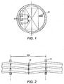
- Figure 1 shows a typical tunnel cross section for a 3m diameter tunnel 10.
- a side of the tunnel has a cable support structure 12 with mounting positions for three cables 14, as shown.
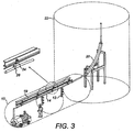
- Figure 2 shows how the cables are to be mounted on the support structures 12.
- the support structures are bolted to the tunnel wall, spaced 7.2m along the tunnel length.
- the cables are mounted with cable cleats, and the cables are desired to have a controlled amount of sag, to permit expansion.
- the sag should be the same for all three cables so that short circuit straps 16 can be fitted mid-way between the support locations.
- the cable can for example comprise a high power electric 400kV cable.
- Common tunnel diameters are 3m and 4m, and the cables can be provided in lengths of the order of 1 km, with typical diameters up to 160mm, although the invention is not limited to any particular cable sizes.
- a 1100m length typically weighs approximately 55 tonnes (50 Kg/m).
- the apparatus of this invention carries out essentially the same operation but the apparatus is designed to allow full bidirectional capability.
- a two stage mounting operation is provided.
- the cable is lowered into the tunnel and is tugged into position.
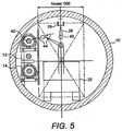
- the cable is suspended in a temporary position suspended from the tunnel roof.
- a support I-beam 19 typically runs along the tunnel roof.
- a cable guiding structure 20 facilitates entry of the cable into an access shaft 22.
- the access shaft can comprise a 1.5m x 2m opening, which may be approximately 5m long.
- the tunnel also has a working envelope of approximately 2m x 1.5m so that there is space for the passage of staff around the working envelope.
- rollers 24 are fitted over the I-beam 19 with cable hangers 26 that support the cable 14.
- the cable is offloaded from a drum 30 in an offload area 31.
- the cable is driven by caterpillars 34 and electric rollers 35 in region 37.
- Various load sensors 36 are used for feedback purposes. Feedback from the sensors as well as CCTV cameras is provided to a control module 38.
- the cable is lowered using controlled motorised rollers which control the rate of cable advance.
- the tunnel typically has a minimum tunnel bend radius of 250m.
- Figure 5 shows the tug 32, cables 14, support structure 12, I-beam 19 and hanger 26 inside the tunnel.
- the previously proposed apparatus provides a design of tug which can perform the towing task explained above, and this aided by a traction control system.
- the design can also perform cable movement from the temporary suspended position 40 to the desired supported position 42, namely the transfer represented by arrow 44.
- the apparatus can provide a desired amount of sag between adjacent support structures 12.
- Figure 6 shows the cable in its temporary position.
- the rollers 24 are spaced by Kevlar bars 60 so that the regular spacing of the rollers 24 is maintained when they are pulled along the I-beam from the entry point of the cable. There may for example be hundreds of the rollers 24 along the length of the cable.
- the bars 60 function as the primary tension members rather than the cable.
- This towing is shown in Figure 3 and also in Figure 7 , and the cable is also pushed from the access shaft end by one of the caterpillars.
- the towing is typically carried out at walking pace, for example 3km/hr.
- the device of the invention When the cable is in its temporary position along its full length, the device of the invention performs the transfer and sagging process.
- the transfer process is shown schematically in Figure 8 .
- the apparatus used is a motorised vehicle.
- a cable positioning arm 80 is at one end of the vehicle which is controllable to move a cable from the temporary position to a final installation position, as shown by arrow 82.
- a cable sagging arm 84 is at the other end of the vehicle which is controllable to apply a desired amount of sagging to a length of cable between adjacent support structures 12.
- the cable positioning arm 80 comprises a roller arrangement for surrounding the cable on the end of an arm.
- the arm has adjustable length and is rotatable about an elongate axis of the vehicle, so that the movement of arrow 44 in Figure 5 can be provided to the cable.
- first portion of the cable After a first portion of the cable has been moved from the temporary installation position to the final installation position it is secured in place, for example as shown at location 86.
- a second portion of the cable is also moved from the temporary installation position to a final installation position using the cable positioning arm, as shown at location 88.
- the cable sagging arm 84 At the position shown in Figure 9 , the cable sagging arm 84 is in position to apply a desired amount of sagging to the length of cable between the first and second locations 86,88.
- the cable at the second location 88 is then secured to the securing point on the wall of the tunnel to retain and fix the sagging amount that has been set.
- the rollers of the cable position arm surround the cable, and the free end of the cable is fed through the opening defined by the rollers.
- the cable positioning arm thus provides support for the cable for the entire operation.
- the cable hangers are removed, to allow the cable to be moved to the support structures 12.
- the cable is elevated to enable release of the cable hanger, before the cable is moved to the support structure.
- the cable sagging arm comprises a guide arrangement for applying a downward sagging force to the cable or for lifting the cable if required.
- the distance along the tunnel axis between the cable sagging arm and the cable positioning arm is preferably at least equal to the distance between final installation positions.
- the distance is preferably approximately equal to the distance between supports 12. This means that the cable sagging arm has reached the position where cable sagging is controlled when the cable positioning arm is in a suitable position for positioning the cable at the next support 12 (as shown in Figure 9 ).
- the cable installation and sagging functions are alternated.
- the machine travels a distance corresponding to the pitch between installation points (e.g. 7.2m) then remains stationary for one cable installation and one cable sagging operation.
- the amount of sag can be controlled by measurement, for example marking the desired sag on the side wall of the tunnel, for example with 195 - 205mm of sag from the horizontal.
- the cable positioning arm and the cable sagging arm are interchangeable so that the device can be driven in both directions.
- the vehicle has five sections; a central motor section, two axle unit sections and two end cab sections.
- This modular design enables the sections to be lowered into the access shaft 22 ( Figure 3 ) individually, and they can be assembled at the base of the access shaft.
- a heavy duty crane system is used to lower the modules down the access shaft.
- the vehicle can comprise at least three sections which are adapted to be assembled within the tunnel.
- Figures 10 and 11 show one preferred version of the previously proposed vehicle more clearly, in side view and in end view in the tunnel.
- the wheeled axle units each comprise two wheels (for example of 700mm diameter and 300mm width) having rotation axes 140 which can be adjusted, such that the wheels can be positioned for rolling on a flat surface or for rolling on opposite inclines.
- the axle units can thus be set for different tunnel diameters.
- a two or four wheel steering system can be provided.
- a tow point 142 is used for the initial towing operation
- Figure 11 shows most clearly how the positioning arm enables the cable to be moved between any two positions in the tunnel cross section, by combining linear and rotational control.
- the same two degrees of freedom can be provided in the sagging arm 84, and a downward force can be applied by rotating the arm once the cable has been engaged.
- the cable securing method can be carried out by driving the vehicle along the tunnel, with manual removal of the hangers.
- the vehicle can be designed so that the cable positioning of one section of cable and the cable sagging of another section are at the same vehicle position. This provides an efficient process, with the vehicle advanced in steps, and at each step a dual positioning and sagging operation is carried out. By controlling the sagging to be the same for multiple cables (installed one after the other) cable ties can more easily be fitted.
- the machine is bi-directional in operation and requires an operator in each cab in order to allow the machine to move, except in an Emergency recovery mode where a key operated override switch will allow a single operator to control all functions of the machine without interruption by any safety override system.
- the two operator control stations conform to a master / slave protocol where only one of the operators has control of the traction power and he will only be able to drive the machine in the direction in which he faces.
- the master operator will have control of the steering of the wheels at his end of the machine. Part of the procedure for handing over control to the other operator is to set these wheels to the straight ahead position and to engage a steering lock.
- This invention provides a more adaptable apparatus. Two examples are shown, one in Figure 12(a) and one in Figure 12(b) .
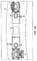
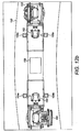
- Figures 12(a) and 12(b) shows the apparatus in plan view within a tunnel 150.
- the machine is again bi-directional but can also perform the cable fixing and sagging operations in either direction of movement.
- all of the controls and the machine functionality are mirrored about the centre of the machine.
- the bi-directional ability provides significant flexibility, especially when installing cables in a tunnel of significant length with multiple delivery shafts into which the cable is delivered.
- the direction of travel and therefore the direction in which the cable is hauled through the tunnel can be dependent on many factors and without the available space within the tunnel environment to manoeuvre and turn, bi-directional control is important.
- This design enables the direction of cable insertion and the direction of cable fixing independent, and this adds flexibility and increases the number of installations for which the apparatus is suitable,
- the principle objective of the machine is to satisfy both the cable delivery and installation; hauling the cable to the desired position before manipulating the cable into its final installed position.
- the apparatus has two manipulating arms 151,152 with one at each end of the machine.
- the example of Figure 12(a) has two sagging rollers 154,156, again with one essentially at each end of the machine.
- the example of Figure 12(b) has two sagging rollers at each end, so that one pair 154a,154b is at one end and the other pair 154a,154b is at the other end.
- one manipulating arm and one sagging arm at opposite ends are used as a pair, and the other manipulating arm and sagging arm are not used.
- the other manipulating arm and the other sagging arm are used as a pair, with the first manipulating arm and sagging arm not used.
- the engine unit 158 is shown in the centre, and there are two operator cabins 160,162 with one at each end, as in the previous version.
- the manipulating arm has three main functions; (i) For hauling the cable to the desired position.
- a gripper assembly is anchored to the end of the manipulating arm, which securely grasps a towing attachment that incorporates a load cell.
- a bond is secured from the towing attachment to the monorail cable delivery system (MCDS) which suspends the cable from beneath on wheeled trolleys, thus allowing the cable to be delivered through the tunnel without any contact with the tunnel wall itself.
- the manipulating arm directs the required towing force through the MCDS bond as opposed to directing the force through the cable itself.
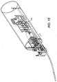
- Figure 13 shows the apparatus hauling the cable from left to right.
- the machine will not apply any force directly to the cable, and the manipulating arm is instead anchored to the monorail cable delivery system not shown in Figure 13 .
- the cable gripping is shown at position 170, using the manipulating arm.
- Figure 14 shows the manipulating arm manoeuvring the cable to the desired installation height at location 172. Once the cable is in the correct plane, the machine will thread the remaining cable.
- Figure 15 shows the sagging roller positioned directly above the cable at position 174.
- a platform of the operator cabin can be raised and lowered with the sagging roller fixed to the cabin platform. With the operator platform in the lowered position, the roller lowers with the platform and the correct sag is introduced into the cable.
- the apparatus has two operating platforms that house all of the controls to operate the drive and cable manipulating functions.
- Each operator platform is associated with a cable manipulating arm and roller.
- the operator platform includes two sagging arm and roller assemblies per platform. This then allows the apparatus to introduce sag into the cables in circuits on either side of the machine.
- the retractable and adjustable arms are mounted to the operator platforms and have both manual and mechanised control. Height adjustment to accommodate the correct phase is conducted manually and set. The fine adjustment and the process of introducing the sag is controlled by the hydraulic vertical and horizontal placement of the operator platform.
- the arm/roller rotates about a vertical axis through 90 degrees so that it can be retracted or laterally deployed. When laterally deployed, it is ready to introduce the required sag. The operator has full control of the sagging displacement.
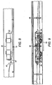
- Figure 16 shows the machine in side view, using the same references as in Figure 12 .
- the cable support bracket 180 is also shown as well as the cables 182.
- the apparatus has the ability to pull cable into the tunnel without the requirement for a monorail beam.
- the manipulating arm can position itself horizontally and pull the cable through and past the steel brackets whilst the cable is supported by cable rollers mounted to the cable brackets.
- the apparatus is preferably a 4 wheel drive and 4 wheel steer machine.
- Various proximity sensors and tilt sensors can be incorporated to measure the machine position relative to objects within the tunnel and the tunnel itself. These sensors prevent the machine from striking foreign objects/tunnel furniture/people.
- the apparatus can typically work in tunnel diameters of 3m - 4m, although it can be designed for tunnels down to 1.5m diameter, and install cable circuits (of any voltage) on both sides of the tunnel.
- the machine has a modular design. There is the central engine module, and platform modules upstream and downstream of the central module.
- the platform modules each carrying one or two cable/pipe sagging arms as explained above.
- Positioning modules are also upstream and downstream of the central module, and each positioning module carries a cable/pipe positioning arm.
- each cable/pipe positioning arm is movable between opposite lateral sides of the vehicle (as seen in Figure 11 ) so that only one is needed even to install cables on both sides.
- each positioning module can have a cable/pipe positioning arm on each opposite lateral side of the vehicle.
- the machine can be petrol/diesel powered or it can be battery powered.
- the invention provides a modular design of vehicle which offers versatility, and allows implementation of a semi-automated cable sagging process, and which reduces health and safety risks associated with alternative methods of introducing sagging into the cables.
- the process is more efficient and can thus reduce operation times.
Landscapes
- Engineering & Computer Science (AREA)
- General Engineering & Computer Science (AREA)
- Mechanical Engineering (AREA)
- Chemical & Material Sciences (AREA)
- Combustion & Propulsion (AREA)
- Laying Of Electric Cables Or Lines Outside (AREA)
Claims (9)
- Vorrichtung zum Installieren von Kabeln oder Rohren in Tunneln, umfassend ein motorisiertes Fahrzeug 32 mit einem Kabel-/Rohrpositionierungsarm 80 an jedem Ende des Fahrzeugs, der gesteuert werden kann, um ein Kabel/Rohr von einer temporären Installationsposition zu einer finalen Installationsposition zu bewegen, wobei jeder Kabel-/Rohrpositionierungsarm einem Kabel-/Rohrsenkungsarm 84, der steuerbar ist, um den gewünschten Betrag an Senkung für eine Länge von Kabel/Rohr zwischen benachbarten finalen Installationspositionen anzuwenden, zugeordnet ist und von diesem beabstandet ist.
- Vorrichtung nach Anspruch 1, umfassend eine erste Endhälfte und eine zweite Endhälfte, wobei jede Endhälfte über einen Kabel-/Rohrpositionierungsarm 80 und einen Kabel-/Rohrsenkungsarm 84 verfügt, wobei der Kabel-/Rohrpositionierungsarm an einem Ende dem Kabel-/Rohrsenkungsarm am anderen Ende zugewiesen ist.
- Vorrichtung nach Anspruch 1 oder 2, wobei jedes Ende des Fahrzeugs über einen Kabel-/Rohrpositionierungsarm 80 an jeder Seite des Fahrzeugs verfügt.
- Vorrichtung nach Anspruch 1 oder 2, wobei jedes Ende des Fahrzeugs über einen Kabel-/Rohrsenkungsarm 84 an jeder Seite des Fahrzeugs verfügt.
- Vorrichtung nach einem der vorstehenden Ansprüche, umfassend ein modulares Design, wobei ein zentrales Motormodul und dem zentralen Modul vorgeschaltete und nachgeschaltete Plattformmodule vorhanden sind, wobei die Plattformmodule jeweils einen Kabel-/Rohrsenkungsarm 84 tragen.
- Vorrichtung nach Anspruch 5, wobei jedes Plattformmodul einen Kabel-/Rohrsenkungsarm 84 an jeder seitlichen Seite trägt.
- Vorrichtung nach Anspruch 5 oder 6, umfassend dem zentralen Modul vorgeschaltete und nachgeschaltete Positionierungsmodule, wobei jedes Positionierungsmodul einen Kabel-/Rohrpositionierungsarm 80 trägt.
- Vorrichtung nach Anspruch 7, wobei jeder Kabel-/Rohrpositionierungsarm 80 zwischen gegenüberliegenden seitlichen Seiten des Fahrzeugs beweglich ist.
- Vorrichtung nach Anspruch 7, wobei jedes Positionierungsmodul über einen Kabel-/Rohrpositionierungsarm 80 an jeder gegenüberliegenden seitlichen Seiten des Fahrzeugs verfügt.
Applications Claiming Priority (2)
| Application Number | Priority Date | Filing Date | Title |
|---|---|---|---|
| GB1222992.8A GB2509093A (en) | 2012-12-20 | 2012-12-20 | Vehicle for cable or pipe installation in tunnels |
| PCT/GB2013/053341 WO2014096819A1 (en) | 2012-12-20 | 2013-12-18 | Method and apparatus for the installation of cables or pipes in tunnels |
Publications (2)
| Publication Number | Publication Date |
|---|---|
| EP2936633A1 EP2936633A1 (de) | 2015-10-28 |
| EP2936633B1 true EP2936633B1 (de) | 2016-11-02 |
Family
ID=47631069
Family Applications (1)
| Application Number | Title | Priority Date | Filing Date |
|---|---|---|---|
| EP13821505.8A Active EP2936633B1 (de) | 2012-12-20 | 2013-12-18 | Verfahren und vorrichtung zur montieren von kabel und rohren in tunnel. |
Country Status (5)
| Country | Link |
|---|---|
| US (1) | US20150330532A1 (de) |
| EP (1) | EP2936633B1 (de) |
| CA (1) | CA2895894A1 (de) |
| GB (1) | GB2509093A (de) |
| WO (1) | WO2014096819A1 (de) |
Families Citing this family (8)
| Publication number | Priority date | Publication date | Assignee | Title |
|---|---|---|---|---|
| US10047893B2 (en) * | 2016-07-15 | 2018-08-14 | Kiewit Infrastructure West Co. | In-situ pipe carrier |
| EP3717814B1 (de) * | 2017-12-01 | 2023-07-12 | Hyperloop Technologies, Inc. | Segmentrohre |
| CN109638722B (zh) * | 2018-12-13 | 2024-07-16 | 江苏华宇电力发展有限公司 | 一种圆弧型隧道电缆支架安装用轻便快速定位仪 |
| IT202000019975A1 (it) * | 2020-08-11 | 2022-02-11 | Prysmian Spa | Metodo e attrezzatura per l’installazione di un cavo di potenza in un tunnel |
| CN113236853A (zh) * | 2021-05-07 | 2021-08-10 | 岭南水务集团有限公司 | 一种长距离穿堤套管内安装洞穿管的设备及其方法 |
| CN113315034A (zh) * | 2021-06-08 | 2021-08-27 | 武汉船用机械有限责任公司 | 一种穿线拉线引导装置 |
| CN115111432B (zh) * | 2022-07-05 | 2023-08-08 | 合肥海博工程设计集团有限公司 | 一种城市雨污水管网施工用放置结构 |
| CN116122906A (zh) * | 2022-11-23 | 2023-05-16 | 中铁工程装备集团有限公司 | 管线延伸装置及隧道掘进设备 |
Family Cites Families (6)
| Publication number | Priority date | Publication date | Assignee | Title |
|---|---|---|---|---|
| US3851481A (en) * | 1972-10-20 | 1974-12-03 | Automation Equipment Inc | Multi-purpose vehicle for use underground |
| JPS637121A (ja) * | 1986-06-25 | 1988-01-13 | 東京都 | 管内ケ−ブルの施設方法および施設装置 |
| DE19751415C2 (de) * | 1997-09-26 | 2001-05-23 | Berliner Wasserbetriebe | Vorrichtung zum Greifen, Positionieren und Fixieren von Befestigungselementen in Hohlräumen unterschiedlicher Querschnitte |
| DE19940474B4 (de) * | 1998-08-27 | 2004-02-12 | Jt-Elektronik Gmbh | Vorrichtung und Verfahren zur Verlegung von Kabeln in Rohren |
| GB2383200B (en) * | 2001-12-12 | 2005-01-12 | Balfour Beatty Plc | Cable installation |
| GB2468883B (en) * | 2009-03-25 | 2012-06-06 | Balfour Beatty Plc | Method and apparatus for the installation of cables or pipes in tunnels |
-
2012
- 2012-12-20 GB GB1222992.8A patent/GB2509093A/en not_active Withdrawn
-
2013
- 2013-12-18 CA CA2895894A patent/CA2895894A1/en not_active Abandoned
- 2013-12-18 EP EP13821505.8A patent/EP2936633B1/de active Active
- 2013-12-18 US US14/654,290 patent/US20150330532A1/en not_active Abandoned
- 2013-12-18 WO PCT/GB2013/053341 patent/WO2014096819A1/en not_active Ceased
Also Published As
| Publication number | Publication date |
|---|---|
| EP2936633A1 (de) | 2015-10-28 |
| US20150330532A1 (en) | 2015-11-19 |
| GB2509093A (en) | 2014-06-25 |
| WO2014096819A1 (en) | 2014-06-26 |
| CA2895894A1 (en) | 2014-06-26 |
| GB201222992D0 (en) | 2013-01-30 |
Similar Documents
| Publication | Publication Date | Title |
|---|---|---|
| EP2936633B1 (de) | Verfahren und vorrichtung zur montieren von kabel und rohren in tunnel. | |
| KR101964633B1 (ko) | 레일을 이용한 지중 케이블의 기계화 포설 장치 | |
| KR102351517B1 (ko) | 케이블 포설장치 | |
| CN110803589B (zh) | 电缆收放及起重一体组合车 | |
| AU2020379558B2 (en) | System for facilitating delivery, placement, and/or installation of a cable | |
| EP3955402B1 (de) | Verfahren und ausrüstung zur installation eines stromkabels in einem tunnel | |
| CN109139098A (zh) | 一种无极绳牵引单轨吊系统 | |
| WO2012003526A1 (en) | A suspended rail system | |
| KR20170061932A (ko) | 지중 케이블 포설 공법 | |
| GB2468883A (en) | Method and apparatus for the installation of cables or pipes in tunnels | |
| CN110814712B (zh) | 轨道梁安装钻车 | |
| JP2014098246A (ja) | セグメント台車の移送装置と移送方法 | |
| WO2015020768A2 (en) | Truck and installation method for wires | |
| CN112448327B (zh) | 一种管线施工方法及施工辅助装置 | |
| ZA200608639B (en) | Railway rail handling apparatus and method | |
| CN212318031U (zh) | 隧道防水板铺设台车 | |
| CN117552831A (zh) | 一种运输台车、斜井隧洞内的钢管运输系统及施工方法 | |
| CN113788369B (zh) | 一种电缆敷设收放装置及其使用方法 | |
| CN111969479B (zh) | 一种垂直排列导线出线带电作业方法 | |
| CN208078536U (zh) | 一种实用型铁路轮胎式电动双向电缆放线车 | |
| CN113799044A (zh) | 一种胶带更换车的使用方法 | |
| US3185444A (en) | Method of installing cable on existing messenger | |
| KR100320278B1 (ko) | 전선의 가선장치(架線裝置) | |
| CN115173319B (zh) | 一种用于大深度竖井的电缆敷设方法 | |
| CN218778028U (zh) | 水库坡面材料运输牵引设备 |
Legal Events
| Date | Code | Title | Description |
|---|---|---|---|
| PUAI | Public reference made under article 153(3) epc to a published international application that has entered the european phase |
Free format text: ORIGINAL CODE: 0009012 |
|
| 17P | Request for examination filed |
Effective date: 20150717 |
|
| AK | Designated contracting states |
Kind code of ref document: A1 Designated state(s): AL AT BE BG CH CY CZ DE DK EE ES FI FR GB GR HR HU IE IS IT LI LT LU LV MC MK MT NL NO PL PT RO RS SE SI SK SM TR |
|
| AX | Request for extension of the european patent |
Extension state: BA ME |
|
| DAX | Request for extension of the european patent (deleted) | ||
| GRAP | Despatch of communication of intention to grant a patent |
Free format text: ORIGINAL CODE: EPIDOSNIGR1 |
|
| INTG | Intention to grant announced |
Effective date: 20160527 |
|
| GRAS | Grant fee paid |
Free format text: ORIGINAL CODE: EPIDOSNIGR3 |
|
| GRAA | (expected) grant |
Free format text: ORIGINAL CODE: 0009210 |
|
| AK | Designated contracting states |
Kind code of ref document: B1 Designated state(s): AL AT BE BG CH CY CZ DE DK EE ES FI FR GB GR HR HU IE IS IT LI LT LU LV MC MK MT NL NO PL PT RO RS SE SI SK SM TR |
|
| REG | Reference to a national code |
Ref country code: GB Ref legal event code: FG4D |
|
| REG | Reference to a national code |
Ref country code: AT Ref legal event code: REF Ref document number: 842701 Country of ref document: AT Kind code of ref document: T Effective date: 20161115 Ref country code: CH Ref legal event code: EP |
|
| REG | Reference to a national code |
Ref country code: IE Ref legal event code: FG4D |
|
| REG | Reference to a national code |
Ref country code: DE Ref legal event code: R096 Ref document number: 602013013666 Country of ref document: DE |
|
| PG25 | Lapsed in a contracting state [announced via postgrant information from national office to epo] |
Ref country code: LV Free format text: LAPSE BECAUSE OF FAILURE TO SUBMIT A TRANSLATION OF THE DESCRIPTION OR TO PAY THE FEE WITHIN THE PRESCRIBED TIME-LIMIT Effective date: 20161102 |
|
| REG | Reference to a national code |
Ref country code: NL Ref legal event code: MP Effective date: 20161102 |
|
| REG | Reference to a national code |
Ref country code: LT Ref legal event code: MG4D |
|
| REG | Reference to a national code |
Ref country code: AT Ref legal event code: MK05 Ref document number: 842701 Country of ref document: AT Kind code of ref document: T Effective date: 20161102 |
|
| PG25 | Lapsed in a contracting state [announced via postgrant information from national office to epo] |
Ref country code: SE Free format text: LAPSE BECAUSE OF FAILURE TO SUBMIT A TRANSLATION OF THE DESCRIPTION OR TO PAY THE FEE WITHIN THE PRESCRIBED TIME-LIMIT Effective date: 20161102 Ref country code: GR Free format text: LAPSE BECAUSE OF FAILURE TO SUBMIT A TRANSLATION OF THE DESCRIPTION OR TO PAY THE FEE WITHIN THE PRESCRIBED TIME-LIMIT Effective date: 20170203 Ref country code: NO Free format text: LAPSE BECAUSE OF FAILURE TO SUBMIT A TRANSLATION OF THE DESCRIPTION OR TO PAY THE FEE WITHIN THE PRESCRIBED TIME-LIMIT Effective date: 20170202 Ref country code: LT Free format text: LAPSE BECAUSE OF FAILURE TO SUBMIT A TRANSLATION OF THE DESCRIPTION OR TO PAY THE FEE WITHIN THE PRESCRIBED TIME-LIMIT Effective date: 20161102 Ref country code: NL Free format text: LAPSE BECAUSE OF FAILURE TO SUBMIT A TRANSLATION OF THE DESCRIPTION OR TO PAY THE FEE WITHIN THE PRESCRIBED TIME-LIMIT Effective date: 20161102 |
|
| PG25 | Lapsed in a contracting state [announced via postgrant information from national office to epo] |
Ref country code: PT Free format text: LAPSE BECAUSE OF FAILURE TO SUBMIT A TRANSLATION OF THE DESCRIPTION OR TO PAY THE FEE WITHIN THE PRESCRIBED TIME-LIMIT Effective date: 20170302 Ref country code: PL Free format text: LAPSE BECAUSE OF FAILURE TO SUBMIT A TRANSLATION OF THE DESCRIPTION OR TO PAY THE FEE WITHIN THE PRESCRIBED TIME-LIMIT Effective date: 20161102 Ref country code: FI Free format text: LAPSE BECAUSE OF FAILURE TO SUBMIT A TRANSLATION OF THE DESCRIPTION OR TO PAY THE FEE WITHIN THE PRESCRIBED TIME-LIMIT Effective date: 20161102 Ref country code: IS Free format text: LAPSE BECAUSE OF FAILURE TO SUBMIT A TRANSLATION OF THE DESCRIPTION OR TO PAY THE FEE WITHIN THE PRESCRIBED TIME-LIMIT Effective date: 20170302 Ref country code: BE Free format text: LAPSE BECAUSE OF NON-PAYMENT OF DUE FEES Effective date: 20161231 Ref country code: ES Free format text: LAPSE BECAUSE OF FAILURE TO SUBMIT A TRANSLATION OF THE DESCRIPTION OR TO PAY THE FEE WITHIN THE PRESCRIBED TIME-LIMIT Effective date: 20161102 Ref country code: HR Free format text: LAPSE BECAUSE OF FAILURE TO SUBMIT A TRANSLATION OF THE DESCRIPTION OR TO PAY THE FEE WITHIN THE PRESCRIBED TIME-LIMIT Effective date: 20161102 Ref country code: AT Free format text: LAPSE BECAUSE OF FAILURE TO SUBMIT A TRANSLATION OF THE DESCRIPTION OR TO PAY THE FEE WITHIN THE PRESCRIBED TIME-LIMIT Effective date: 20161102 Ref country code: RS Free format text: LAPSE BECAUSE OF FAILURE TO SUBMIT A TRANSLATION OF THE DESCRIPTION OR TO PAY THE FEE WITHIN THE PRESCRIBED TIME-LIMIT Effective date: 20161102 |
|
| REG | Reference to a national code |
Ref country code: DE Ref legal event code: R119 Ref document number: 602013013666 Country of ref document: DE |
|
| PG25 | Lapsed in a contracting state [announced via postgrant information from national office to epo] |
Ref country code: DK Free format text: LAPSE BECAUSE OF FAILURE TO SUBMIT A TRANSLATION OF THE DESCRIPTION OR TO PAY THE FEE WITHIN THE PRESCRIBED TIME-LIMIT Effective date: 20161102 Ref country code: CZ Free format text: LAPSE BECAUSE OF FAILURE TO SUBMIT A TRANSLATION OF THE DESCRIPTION OR TO PAY THE FEE WITHIN THE PRESCRIBED TIME-LIMIT Effective date: 20161102 Ref country code: EE Free format text: LAPSE BECAUSE OF FAILURE TO SUBMIT A TRANSLATION OF THE DESCRIPTION OR TO PAY THE FEE WITHIN THE PRESCRIBED TIME-LIMIT Effective date: 20161102 Ref country code: RO Free format text: LAPSE BECAUSE OF FAILURE TO SUBMIT A TRANSLATION OF THE DESCRIPTION OR TO PAY THE FEE WITHIN THE PRESCRIBED TIME-LIMIT Effective date: 20161102 Ref country code: SK Free format text: LAPSE BECAUSE OF FAILURE TO SUBMIT A TRANSLATION OF THE DESCRIPTION OR TO PAY THE FEE WITHIN THE PRESCRIBED TIME-LIMIT Effective date: 20161102 |
|
| REG | Reference to a national code |
Ref country code: CH Ref legal event code: PL |
|
| PG25 | Lapsed in a contracting state [announced via postgrant information from national office to epo] |
Ref country code: BG Free format text: LAPSE BECAUSE OF FAILURE TO SUBMIT A TRANSLATION OF THE DESCRIPTION OR TO PAY THE FEE WITHIN THE PRESCRIBED TIME-LIMIT Effective date: 20170202 Ref country code: IT Free format text: LAPSE BECAUSE OF FAILURE TO SUBMIT A TRANSLATION OF THE DESCRIPTION OR TO PAY THE FEE WITHIN THE PRESCRIBED TIME-LIMIT Effective date: 20161102 Ref country code: BE Free format text: LAPSE BECAUSE OF FAILURE TO SUBMIT A TRANSLATION OF THE DESCRIPTION OR TO PAY THE FEE WITHIN THE PRESCRIBED TIME-LIMIT Effective date: 20161102 Ref country code: SM Free format text: LAPSE BECAUSE OF FAILURE TO SUBMIT A TRANSLATION OF THE DESCRIPTION OR TO PAY THE FEE WITHIN THE PRESCRIBED TIME-LIMIT Effective date: 20161102 |
|
| PLBE | No opposition filed within time limit |
Free format text: ORIGINAL CODE: 0009261 |
|
| STAA | Information on the status of an ep patent application or granted ep patent |
Free format text: STATUS: NO OPPOSITION FILED WITHIN TIME LIMIT |
|
| PG25 | Lapsed in a contracting state [announced via postgrant information from national office to epo] |
Ref country code: MC Free format text: LAPSE BECAUSE OF FAILURE TO SUBMIT A TRANSLATION OF THE DESCRIPTION OR TO PAY THE FEE WITHIN THE PRESCRIBED TIME-LIMIT Effective date: 20161102 |
|
| REG | Reference to a national code |
Ref country code: FR Ref legal event code: ST Effective date: 20170831 |
|
| REG | Reference to a national code |
Ref country code: IE Ref legal event code: MM4A |
|
| 26N | No opposition filed |
Effective date: 20170803 |
|
| PG25 | Lapsed in a contracting state [announced via postgrant information from national office to epo] |
Ref country code: CH Free format text: LAPSE BECAUSE OF NON-PAYMENT OF DUE FEES Effective date: 20161231 Ref country code: LU Free format text: LAPSE BECAUSE OF NON-PAYMENT OF DUE FEES Effective date: 20161218 Ref country code: FR Free format text: LAPSE BECAUSE OF NON-PAYMENT OF DUE FEES Effective date: 20170102 Ref country code: LI Free format text: LAPSE BECAUSE OF NON-PAYMENT OF DUE FEES Effective date: 20161231 |
|
| PG25 | Lapsed in a contracting state [announced via postgrant information from national office to epo] |
Ref country code: SI Free format text: LAPSE BECAUSE OF FAILURE TO SUBMIT A TRANSLATION OF THE DESCRIPTION OR TO PAY THE FEE WITHIN THE PRESCRIBED TIME-LIMIT Effective date: 20161102 Ref country code: IE Free format text: LAPSE BECAUSE OF NON-PAYMENT OF DUE FEES Effective date: 20161218 Ref country code: DE Free format text: LAPSE BECAUSE OF NON-PAYMENT OF DUE FEES Effective date: 20170701 |
|
| PG25 | Lapsed in a contracting state [announced via postgrant information from national office to epo] |
Ref country code: HU Free format text: LAPSE BECAUSE OF FAILURE TO SUBMIT A TRANSLATION OF THE DESCRIPTION OR TO PAY THE FEE WITHIN THE PRESCRIBED TIME-LIMIT; INVALID AB INITIO Effective date: 20131218 |
|
| PG25 | Lapsed in a contracting state [announced via postgrant information from national office to epo] |
Ref country code: CY Free format text: LAPSE BECAUSE OF FAILURE TO SUBMIT A TRANSLATION OF THE DESCRIPTION OR TO PAY THE FEE WITHIN THE PRESCRIBED TIME-LIMIT Effective date: 20161102 Ref country code: MK Free format text: LAPSE BECAUSE OF FAILURE TO SUBMIT A TRANSLATION OF THE DESCRIPTION OR TO PAY THE FEE WITHIN THE PRESCRIBED TIME-LIMIT Effective date: 20161102 |
|
| PG25 | Lapsed in a contracting state [announced via postgrant information from national office to epo] |
Ref country code: MT Free format text: LAPSE BECAUSE OF NON-PAYMENT OF DUE FEES Effective date: 20161218 |
|
| PG25 | Lapsed in a contracting state [announced via postgrant information from national office to epo] |
Ref country code: TR Free format text: LAPSE BECAUSE OF FAILURE TO SUBMIT A TRANSLATION OF THE DESCRIPTION OR TO PAY THE FEE WITHIN THE PRESCRIBED TIME-LIMIT Effective date: 20161102 |
|
| PG25 | Lapsed in a contracting state [announced via postgrant information from national office to epo] |
Ref country code: AL Free format text: LAPSE BECAUSE OF FAILURE TO SUBMIT A TRANSLATION OF THE DESCRIPTION OR TO PAY THE FEE WITHIN THE PRESCRIBED TIME-LIMIT Effective date: 20161102 |
|
| PGFP | Annual fee paid to national office [announced via postgrant information from national office to epo] |
Ref country code: GB Payment date: 20251204 Year of fee payment: 13 |