EP2936014B1 - Haushaltskältegerät - Google Patents
Haushaltskältegerät Download PDFInfo
- Publication number
- EP2936014B1 EP2936014B1 EP13805365.7A EP13805365A EP2936014B1 EP 2936014 B1 EP2936014 B1 EP 2936014B1 EP 13805365 A EP13805365 A EP 13805365A EP 2936014 B1 EP2936014 B1 EP 2936014B1
- Authority
- EP
- European Patent Office
- Prior art keywords
- wall
- support frame
- refrigeration appliance
- household refrigeration
- bounding
- Prior art date
- Legal status (The legal status is an assumption and is not a legal conclusion. Google has not performed a legal analysis and makes no representation as to the accuracy of the status listed.)
- Active
Links
- 238000005057 refrigeration Methods 0.000 title claims description 13
- 238000009413 insulation Methods 0.000 claims description 52
- 239000004033 plastic Substances 0.000 description 11
- 239000000463 material Substances 0.000 description 8
- 235000013305 food Nutrition 0.000 description 6
- VYPSYNLAJGMNEJ-UHFFFAOYSA-N Silicium dioxide Chemical group O=[Si]=O VYPSYNLAJGMNEJ-UHFFFAOYSA-N 0.000 description 4
- 230000002093 peripheral effect Effects 0.000 description 4
- 239000002937 thermal insulation foam Substances 0.000 description 4
- 238000010276 construction Methods 0.000 description 3
- 239000006260 foam Substances 0.000 description 3
- 239000011521 glass Substances 0.000 description 3
- 239000007787 solid Substances 0.000 description 3
- 230000000694 effects Effects 0.000 description 2
- 239000000945 filler Substances 0.000 description 2
- 239000006261 foam material Substances 0.000 description 2
- 238000002347 injection Methods 0.000 description 2
- 239000007924 injection Substances 0.000 description 2
- 238000009434 installation Methods 0.000 description 2
- 238000004519 manufacturing process Methods 0.000 description 2
- 238000007789 sealing Methods 0.000 description 2
- 239000000377 silicon dioxide Substances 0.000 description 2
- 230000007704 transition Effects 0.000 description 2
- 239000000853 adhesive Substances 0.000 description 1
- 238000004026 adhesive bonding Methods 0.000 description 1
- 230000001070 adhesive effect Effects 0.000 description 1
- 230000015572 biosynthetic process Effects 0.000 description 1
- 239000011248 coating agent Substances 0.000 description 1
- 238000000576 coating method Methods 0.000 description 1
- 239000002131 composite material Substances 0.000 description 1
- 230000001066 destructive effect Effects 0.000 description 1
- 239000003000 extruded plastic Substances 0.000 description 1
- 239000011810 insulating material Substances 0.000 description 1
- 239000012774 insulation material Substances 0.000 description 1
- 230000010354 integration Effects 0.000 description 1
- 238000012856 packing Methods 0.000 description 1
- 230000002265 prevention Effects 0.000 description 1
- 230000000284 resting effect Effects 0.000 description 1
- 238000003466 welding Methods 0.000 description 1
Images


Classifications
-
- F—MECHANICAL ENGINEERING; LIGHTING; HEATING; WEAPONS; BLASTING
- F25—REFRIGERATION OR COOLING; COMBINED HEATING AND REFRIGERATION SYSTEMS; HEAT PUMP SYSTEMS; MANUFACTURE OR STORAGE OF ICE; LIQUEFACTION SOLIDIFICATION OF GASES
- F25D—REFRIGERATORS; COLD ROOMS; ICE-BOXES; COOLING OR FREEZING APPARATUS NOT OTHERWISE PROVIDED FOR
- F25D23/00—General constructional features
- F25D23/02—Doors; Covers
-
- F—MECHANICAL ENGINEERING; LIGHTING; HEATING; WEAPONS; BLASTING
- F25—REFRIGERATION OR COOLING; COMBINED HEATING AND REFRIGERATION SYSTEMS; HEAT PUMP SYSTEMS; MANUFACTURE OR STORAGE OF ICE; LIQUEFACTION SOLIDIFICATION OF GASES
- F25D—REFRIGERATORS; COLD ROOMS; ICE-BOXES; COOLING OR FREEZING APPARATUS NOT OTHERWISE PROVIDED FOR
- F25D23/00—General constructional features
- F25D23/06—Walls
- F25D23/065—Details
-
- F—MECHANICAL ENGINEERING; LIGHTING; HEATING; WEAPONS; BLASTING
- F25—REFRIGERATION OR COOLING; COMBINED HEATING AND REFRIGERATION SYSTEMS; HEAT PUMP SYSTEMS; MANUFACTURE OR STORAGE OF ICE; LIQUEFACTION SOLIDIFICATION OF GASES
- F25D—REFRIGERATORS; COLD ROOMS; ICE-BOXES; COOLING OR FREEZING APPARATUS NOT OTHERWISE PROVIDED FOR
- F25D2201/00—Insulation
- F25D2201/10—Insulation with respect to heat
- F25D2201/14—Insulation with respect to heat using subatmospheric pressure
-
- Y—GENERAL TAGGING OF NEW TECHNOLOGICAL DEVELOPMENTS; GENERAL TAGGING OF CROSS-SECTIONAL TECHNOLOGIES SPANNING OVER SEVERAL SECTIONS OF THE IPC; TECHNICAL SUBJECTS COVERED BY FORMER USPC CROSS-REFERENCE ART COLLECTIONS [XRACs] AND DIGESTS
- Y02—TECHNOLOGIES OR APPLICATIONS FOR MITIGATION OR ADAPTATION AGAINST CLIMATE CHANGE
- Y02B—CLIMATE CHANGE MITIGATION TECHNOLOGIES RELATED TO BUILDINGS, e.g. HOUSING, HOUSE APPLIANCES OR RELATED END-USER APPLICATIONS
- Y02B40/00—Technologies aiming at improving the efficiency of home appliances, e.g. induction cooking or efficient technologies for refrigerators, freezers or dish washers
Definitions
- the invention relates to a household refrigerator with a wall assembly, the wall assembly comprising a first wall having a thermal insulation body, and a separate second wall which is adjacent and disposed at an angle to the insulating body.
- an inner container may be provided which has an opening on the front side which can be closed by a door.
- the door also represents a wall in the context.
- the thermal insulation body can be provided in different embodiments.
- an insulation foam is provided.
- vacuum insulation elements are known in newer embodiments.
- a housing for a refrigeration device in which an insulating body is delimited by an outer and an inner shell and in an intermediate space between the shells an insulation material pack is arranged.
- the insulating material may be, for example, a highly porous solid.
- the insulation body may have two shells or skins, between which in turn a cavity is formed, which may be evacuated.
- a skin of this insulating body itself has a polygonal frame, to which a plate-like inner skin and an outer skin are then fastened, thereby forming an overall covering for the insulating body.
- a full-surface adhesion may be provided, for example, on an inner container or else on an inner side of the outer container.
- the outer container then form an outer housing wall, the surrounds the inner container.
- the space between the inner container and the outer container may additionally be filled with a thermally insulating foam material.
- the holding of an insulating body is required by additional assembly costs and additional materials, such as foam material for foam coating.
- WO 2007/06554 A1 a freezer door assembly comprising a glass door and a door jamb against which the glass door rests in the closed position via a flexible seal.
- the glass door on a disc composite and the disc assembly is received at its, in the closed position adjacent to the door jamb, vertical edge portion of a frame profile and the flexible seal is disposed between the frame profile and the door jamb.
- the frame profile has a plastic profile base body which is coated on its visible sides at least partially with a decorative layer.
- WO 96/39894 A1 a household appliance having a mounting structure and a plurality of vacuum insulation panels, which are held by the mounting structure, so that they form an insulated shell substantially.
- the wall assembly comprises a first wall, which has a thermal insulation body.
- the wall assembly further comprises a second wall, which is formed separately from the first wall and which is arranged adjacent thereto at an angle to the insulating body.
- the insulating body is held by a separate support frame of the first wall and peripherally surrounded at least partially.
- the support frame comprises a limiting element which, viewed in the depth direction of the first wall, extends behind a rear side of the insulation body and has a boundary side facing the second wall and spaced therefrom. This boundary side of the limiting element forms a small air gap with a boundary side of the second wall.
- a mechanically stable and with regard to the installation effort reduced attachment of an insulating body is made possible.
- the support frame a holder is provided which receives the insulation body and positioned accordingly.
- This additional component in the form of the support frame is also designed to be multifunctional, since it also contributes to the design of an air gap with another component, namely the second wall, in addition to the holding function of the insulating body.
- the air gap extends completely behind the rear side of the insulation body.
- the air gap is limited by a front side of the second wall, which bears against the limiting element.
- the limiting element extends at the back of the insulating body, so that in the context of this limiting element forms a front wall termination of the air gap.
- the air gap is arranged obliquely extending from the insulating body.
- a design brings advantages in terms of the length of the air gap.
- a comparatively larger length of the air gap As a result, the volume of the air gap is increased, so that more stagnant air can stay in the air gap.
- the insulation effect is achieved and consequently improved, the larger this volume of air.
- Due to the inclination moreover, it is also achieved that the delimiting element does not extend with an undesired depth behind the insulating body and thus also extends into the interior defined by the wall arrangement. The useful volume of this interior is not undesirably restricted.
- the limiting element is a hollow profile body.
- this limiting element is a hollow profile body closed in cross-section.
- a mechanically particularly stable component is created, which is, however, formed by the cavity construction, however, very low in weight.
- just by such a geometry also creates the possibility that even more functionalities are attached to the boundary element.
- further own separate functional components are attached to this limiting element or can be attached.
- the support frame is angular and has the angular geometry forming carrier frame parts.
- the support frame is formed integrally with its support frame parts.
- an injection-molded component can be formed.
- the support frame is then made of plastic. It can be provided that the support frame of a Plastic material or made of at least two different plastic materials, for example as a 2K injection molded part.
- the support frame is formed from a plurality of separate support frame parts, which can then be connected by appropriate connections. It may be provided in the context of a nondestructive releasable connection, such as a connector, a snap-in connection or a screw connection. Likewise, however, it is also possible to provide non-destructive, non-detachable connections, such as, for example, a riveted connection or an adhesive connection.
- the carrier frame parts are at least partially formed as a hollow profile body.
- they are designed as closed hollow profile bodies.
- a carrier frame part and a delimiting element are arranged at a distance from one another and are connected to a connecting web.
- Such a configuration of the support frame allows a very compact and weight-saving design, which is nevertheless formed mechanically extremely stable between the support frame part and the limiting element.
- the connection region between the support frame part and the limiting element of the support frame is thus extremely thin and compact.
- a region between the insulating body and the second wall is therefore made very thin, since preferably only this connecting web has to extend therein.
- this embodiment also provides a component which is also highly flexible in the connection region between the support frame part and the delimiting element and can thereby be molded onto a wide variety of geometries.
- the boundary element extends in the cross-section of the wall arrangement extends exclusively behind the insulation body.
- the carrier frame part in Viewed cross section of the wall assembly and seen in the width direction extends only adjacent to the insulating body.
- the support frame part thus surrounds the insulating body only peripherally and thus at its peripheral edge.
- the connecting web considered in cross-section of the wall assembly is adapted to the contour of the insulating body and rests both on a side edge or a peripheral edge of the insulating body and on the rear side.
- the connecting web is thus formed on the insulating body such that it engages around a transition region between said side edge and the back.
- Such a configuration further strengthens the holding function of the support frame for holding the insulating body again substantially.
- a holding device which securely fixes the insulating body in the two spatial directions of the plane in which the insulating body extends, and on the other hand in the third Direction of space perpendicular thereto and thus positionally keeps corresponding in the depth direction.
- the limiting elements are each formed where vertical carrier frame parts are provided. It can be provided that boundary elements are not formed in horizontally oriented carrier frame parts.
- the support frame is formed quadrangular and at least one, the angular geometry on a geometry side limiting, support frame part, in particular on two opposite vertical Carrier frame parts, a limiting element is arranged, which extends at least partially, in particular at least over 90% of the length of this geometry page.
- the already mentioned above multifunctionality of the limiting element, which is formed in addition to the air gap formation under inclusion of another functional part, is designed such that this functional part is a door rack. This is advantageous because the first wall is a door of the household refrigerator.
- the list of special functional parts is not limited by this and it can also be arranged on other functional parts in addition.
- the insulating body is a vacuum insulation element.
- Especially such elements are usually glued in conventional embodiments on the inner container or on an inner side of the outer panel and beyond then also at least partially foamed with a thermal insulation foam.
- a thermal insulation foam In addition to an increased installation effort while other problems, such as an undesirable deformation of the door by shrinking foam can occur.
- the invention provides that the wall is formed with the insulating body as Vollvakuumwandung or full vacuum door.
- the vacuum insulation element is no longer at least partially foamed with a thermal insulation foam. Only this vacuum insulation element serves as the only thermal insulation body.
- the vacuum insulation element is preferably formed plate-like and comprises in a preferred embodiment, an inner shell and an outer shell, which may be interconnected or formed integrally with each other.
- the shells may be formed of specific plastic materials that are single-layered or multi-layered.
- a filling material is preferably silica.
- it can also be provided another porous solid.
- a sealing labyrinth is created in which standing air for thermal insulation is located.
- This seal labyrinth reduces in particular the heat input into the interior, which is limited by the wall assembly, in the region of the usually provided flexible and deformable seal between the two walls.
- This formed air gap through the sealing labyrinth is of particular advantage in the already mentioned above vacuum walls, since they are significantly thinner compared to conventional walls, in which an insulating body and additionally a thermally insulating foam is provided.
- the multi-functionality of the limiting element with the function of receiving additional functional components has the advantage that no attachment of corresponding spars on the first wall is more necessary, which brings significant advantages during deep drawing and subsequent manufacturing process with it. In addition, resulting from the wall assembly greater geometric freedom due to different design and manufacturing capabilities. Especially the attachment of functional parts of the limiting element also brings the distinct advantage that they do not have to be attached to the insulating body and thus no unwanted force is introduced into the insulating body.
- the invention relates to a household refrigerator for receiving food in an interior with a wall assembly according to the invention or an advantageous embodiment thereof.
- an interior of the household refrigerating appliance for receiving food is limited by the wall arrangement.
- Fig. 1 is shown in a perspective view of a household refrigerator 1, which is designed to hold foods such as drinks and food.
- the household refrigerator 1 may be, for example, a refrigerator or a freezer or a combined refrigerated freezer.
- the household refrigerating appliance 1 comprises a housing 2, which comprises an outer housing or an outer container 3 and an inner housing arranged therein, which is an inner container 4.
- the outer container 3 surrounds the inner container 4, wherein both front side have a feed opening which can be closed by a door 5.
- the inner container 4 bounded by lateral walls or side walls 4a and 4b and a rear wall or a rear wall 4c, and a bottom wall 4d and a top wall 4e an interior 6.
- this interior can completely a freezer compartment or include a no-frost compartment or a freezer compartment.
- the household refrigerating appliance 1 has a refrigerating compartment as the interior 6, in the inside of a freezer compartment is integrated, which in particular is then closed by another own freezer door.
- the door 5 for closing the inner space 6 is a vacuum insulation door, in particular a full vacuum door.
- the door 5 has at least one vacuum insulation element which constitutes a thermal insulation body.
- the door 5 also represents a wall of the household refrigerating appliance 1.
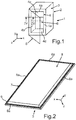
- FIG. 2 is shown in a perspective view, an inside 7 of the door 5 with the vacuum insulation element 8.
- the door 5 comprises in addition to the plate-like rectangular vacuum insulation element 8 a support frame 9.
- the support frame 9 circumferentially surrounds the vacuum insulation element 8 completely.
- the vacuum insulation element 8 is thus held by the support frame 9.
- the support frame 9 is also rectangular in shape and formed in several parts. Of course, a one-piece support frame 9 would be conceivable as well.
- the support frame 9 is also made of plastic and realized in particular by injection molded parts and extruded plastic parts. It can be provided that the support frame 9 is formed from a single plastic material or from at least two different plastic materials.
- Fig. 3 is the door 5 is shown in an exploded view.
- the vacuum insulation element 8 has a rear or inner shell 10, which is integrally formed from plastic.
- the vacuum insulation element 8 comprises a front shell or an outer shell 11, which is also integrally formed from plastic.
- a gluing or welding can be provided here.
- a packing or supporting body 12 is introduced in the intermediate space or cavity formed between the shells 10 and 11.
- a packing or supporting body 12 is introduced in the intermediate space or cavity formed between the shells 10 and 11.
- a packing or supporting body 12 is introduced.
- here can be a porous Be provided solid.
- silica is provided as filler. This gap between the shells 10 and 11 is evacuated.
- a circumferential seal 13 is shown, which is arranged in the assembled state on the support frame 9.
- the support frame 9 is thus designed multifunctional and provided for receiving a plurality of different separate objective components.
- another functional component may additionally be arranged on the support frame 9.
- a hinge and / or a bearing unit and / or a stiffening part can be provided here.
- the support frame 9 by its rectangular shape comprises four support frame parts 14, 15, 16 and 17.
- the horizontally arranged carrier frame parts 15 and 17 extend parallel to each other.
- the door 5 further includes an outside or front cover 18, which is for example a plate-like outer panel.
- the carrier frame parts 14 to 17 can also be integrated and thus embedded on the inside a metallic stiffening part.
- this integration is such that the metallic stiffening part is completely enclosed by the plastic material of the support frame part 14 to 17.
- Fig. 4 is in a horizontal sectional view and thus in a section in the xz plane in Fig. 1 a partial section of the household refrigerator 1 shown.
- a wall assembly 19 is shown having a first wall formed by the door 5.
- the door 5, as already explained, comprises the insulating body, which is designed as a vacuum insulation element 8.
- the door 5 comprises exclusively this at least one vacuum insulation element 8 and is therefore made very thin in the depth direction (z direction). Additional thermal insulation foam which at least partially surrounds the insulating body is not provided.
- the wall assembly 19 comprises, in addition to the door 5, a second wall formed by the vertical side wall 4b.
- the support frame part 16 of the support frame 9 is arranged laterally to the vacuum insulation element 8.
- the carrier frame part 16 formed as a hollow profile body does not extend beyond the dimensions of the vacuum insulation element 8. It is thus only arranged laterally to the vacuum insulation element 8 and thus adjacent to the side edge or peripheral edge 8a.
- the support frame part 16 moreover comprises a delimiting element 20.
- the delimiting element 20 is likewise designed as a hollow profile and, in analogy to the configuration of the support frame part 16, is designed to be completely circumferential in the horizontal sectional view and thus closed. The cavity is thus completely enclosed here peripherally.
- the limiting element 20 is formed completely behind the vacuum insulation element 8 as viewed in the depth direction. In the width direction (x-direction), it is also completely disposed within the width of the vacuum insulation element 8.
- the delimiting element 20 has a limiting side 20 a resting on the vacuum insulation element 8 or on its rear side 7. Subsequently, a boundary side 20b is formed, which faces the adjacent side wall 4b.
- the rear side 4c of the inner container faces a further limiting side 20c, which then merges into a limiting side 20d facing the opposite side wall 4a.
- the thus geometrically formed cross section of the limiting element 20 also allows a multi-functionality. This to the effect that the element 20 viewed from the vacuum insulation element 8 away obliquely viewed obliquely to the side wall 4a oriented boundary side 20b. This is spaced and arranged at least partially parallel to a boundary side 41 b of the side wall 4b. As a result of this embodiment, an air gap 21 is formed between the boundary sides 20b and 41b.
- the support frame part 16 comprises a connecting web 27, which is free of cavities and formed in cross-section as a thin strip.
- this connecting web 27 has a shape in the cross-sectional representation, which is adapted to the rear side 7 and the side edge or peripheral edge 8a and integrally formed thereon.
- the connecting web 27 also forms a boundary wall for the air gap 21 to the vacuum insulation element 8 out.
- a front side 42b of the side wall 4b in the closed state of the door 5 is shown, is applied to the connecting web 27.
- the walls in the form of the door 5 and the side wall 4b are arranged in the closed state of the door 5 substantially at 90 ° to each other.
- the air gap 21 extends over its entire length in the direction of the depth behind the back 7 of the vacuum insulation element 8. In addition, viewed in the width direction of the air gap 21 is also disposed over its entire length completely within the dimensions of the vacuum insulation element 8.
- the limiting element 20 is also also designed as a holder for at least one further functional part, for example a door racks.
- a receptacle 20e may be formed in the limiting element 20, preferably in the boundary sides 20c and / or 20d. In this, the door rack can then be introduced in particular non-destructively releasable.
- FIG. 5 is a perspective view of a further embodiment of a trained as a door 5 first wall, which differs from the embodiment in Fig. 2 is.
- the support frame 9 is formed completely circumferentially and also the limiting element 20 is designed completely encircling.
- the limiting element 20 is not explicitly shown.
- Fig. 5 In contrast, it is provided that only the vertical support frame parts 14 and 16 each have limiting elements 20 and 22. As can be seen, the delimiting elements 20 and 22 extend rectilinearly in the height direction and thus in the y direction and moreover in particular at least over 90% of the length of the respective geometry sides of the quadrangular support frame 9 Fig. 5
- hinges 23 and 24 are also shown by way of example, by means of which the door 5 is struck on the housing 2.
- Fig. 5 are also the boundary sides 22a, 22b, 22c and 22d of the limiting element 22 located and beyond in Fig. 6 also recordings 22e for more functional parts.
- a connecting web 28 analogous to the connecting web 27 shown in the limiting element 22.
- Connecting members 25 and 26 are arranged horizontally, which are formed in corresponding recesses in mutually facing boundary sides 20d and 22d.
- the connecting parts 25 and 26 are hooked and fixed in the context at the top and bottom, so that here too with maximum dimensions a square or rectangular geometry is designed. The mechanical stability of the entire construction is thereby increased.
- Fig. 7 is an enlarged partial section of I out Fig. 6 shown. In this case, too, the enlarged illustration of the receptacle 20e in the boundary sides 20c and 20d of the delimiting element 20 is shown.
Description
- Die Erfindung betrifft ein Haushaltskältegerät mit einer Wandungsanordnung, die Wandungsanordnung mit einer ersten Wandung, die einen thermischen Isolationskörper aufweist, und eine separate zweite Wandung umfasst, die benachbart und in einem Winkel zum Isolationskörper angeordnet ist.
- Bei Haushaltskältegeräten, wie beispielsweise einem Kühlgerät oder einem Gefriergerät oder einem Kühl-Gefrier-Kombigerät wird ein Innenraum, in dem Kältegut in Form von Lebensmitteln, die Speisen und Getränke umfassen, durch Wandungen begrenzt. Dazu kann ein Innenbehälter vorgesehen sein, der frontseitig eine Öffnung aufweist, die durch eine Tür verschließbar ist. Auch die Tür stellt in dem Zusammenhang eine Wandung dar.
- Die thermischen Isolationskörper können in unterschiedlicher Ausgestaltung vorgesehen sein. So ist bekannt, dass ein Isolationsschaum vorgesehen ist. Ebenso sind bei neueren Ausgestaltungen Vakuumisolationselemente bekannt. So ist beispielsweise aus der
WO 2012/031885 A2 ein Gehäuse für ein Kältegerät bekannt, bei dem ein Isolationskörper durch eine äußere und eine innere Schale begrenzt ist und in einem Zwischenraum zwischen den Schalen eine Isolationsmaterialpackung angeordnet ist. Das Isolationsmaterial kann beispielsweise ein hochporöser Feststoff sein. - Aus der
DE 10 2009 002 800 A1 ist ein Haushaltskältegerät und eine wärmeisolierende Wandung dafür bekannt. Bei dieser Ausgestaltung kann der Isolationskörper zwei Schalen bzw. Häute aufweisen, zwischen denen wiederum ein Hohlraum ausgebildet ist, der evakuiert sein kann. Bei einer Ausführung kann vorgesehen sein, dass eine Haut dieses Isolationskörpers selbst einen eckigen Rahmen aufweist, an dem dann eine plattenartige Innenhaut und eine Außenhaut befestigt sind, so dass dadurch eine Gesamthülle für den Isolationskörper gebildet ist. - Bei derartigen plattenartigen Isolationskörpern ist die Positionierung und Befestigung schwierig. In dem Zusammenhang kann ein vollflächiges Ankleben beispielsweise an einem Innenbehälter oder aber auch an einer Innenseite des Außenbehälters vorgesehen sein. Beispielsweise kann der Außenbehälter dann eine äußere Gehäusewand bilden, die den Innenbehälter umgibt. Der Zwischenraum zwischen dem Innenbehälter und dem Außenbehälter kann zusätzlich dann noch mit einem thermisch isolierenden Schaummaterial ausgefüllt sein.
- Gerade bei einer Tür ist ein derartiger Aufbau jedoch montageintensiv und die Tür durch die Vielzahl der Komponenten auch relativ dick gestaltet. Dadurch wird entweder das Gerät vergrößert oder ein Nutzvolumen des Innenraums verkleinert.
- Bei den bekannten Anordnungen ist die Einbringung des thermischen Isolationskörpers, welcher auch evakuiert sein kann, relativ aufwändig. Insbesondere auch das Halten eines Isolationskörpers ist durch zusätzlichen Montageaufwand und zusätzliche Materialien, wie beispielsweise Schaummaterial zur Umschäumung erforderlich.
- Ferner beschreibt die
WO 2007/06554 A1 - Ferner beschreibt die
WO 96/39894 A1 - Aus der
DE 1 056 630 ist eine Isolationsanordnung unter Verwendung von thermischen Isolationskörpern bekannt. - Es ist daher Aufgabe, ein Haushaltskältegerät mit einer Wandungsanordnung zu schaffen, die eine mechanisch stabile Halterung des thermischen Isolationskörpers ermöglicht und darüber hinaus der Wärmeaustausch zwischen einem durch die Wandungsanordnung begrenzten Raum und der Umgebung dazu verbessert ist.
- Diese Aufgabe wird durch ein Haushaltskältegerät gemäß dem unabhängigen Anspruch gelöst.
- Bei einem erfindungsgemäßen Haushaltskältegerät umfasst die Wandungsanordnung eine erste Wandung, die einen thermischen Isolationskörper aufweist. Die Wandungsanordnung umfasst darüber hinaus eine zweite Wandung, die separat zur ersten Wandung ausgebildet ist und die benachbart dazu in einem Winkel zum Isolationskörper angeordnet ist. Der Isolationskörper ist von einem separaten Trägerrahmen der ersten Wandung gehalten und umfangsseitig zumindest bereichsweise umgeben. Der Trägerrahmen umfasst ein Begrenzungselement, welches sich in Tiefenrichtung der ersten Wandung betrachtet hinter eine Rückseite des Isolationskörpers erstreckt und eine der zweiten Wandung zugewandte und davon beabstandete Begrenzungsseite aufweist. Diese Begrenzungsseite des Begrenzungselements bildet mit einer Begrenzungsseite der zweiten Wandung einen kleinen Luftspalt. Durch eine derartige Ausgestaltung einer Wandungsanordnung ist eine mechanisch stabile und im Hinblick auf den Montageaufwand reduzierte Anbringung eines Isolationskörpers ermöglicht. Durch den Trägerrahmen wird eine Halterung geschaffen, die den Isolationskörper aufnimmt und entsprechend positioniert. Dieses zusätzliche Bauteil in Form des Trägerrahmens ist darüber hinaus multifunktionell gestaltet, da es neben der Haltefunktion des Isolationskörpers auch gleichzeitig zur Gestaltung eines Luftspalts mit einer anderen Komponente, nämlich der zweiten Wandung, beiträgt. Durch einen derartigen Luftspalt wird gerade am Übergang zwischen der ersten und der zweiten Wandung ein unerwünschter Wärmeaustausch zwischen dem Innenraum, der durch die Wandungsanordnung begrenzt ist, und der Umgebung dazu verhindert.
- Vorzugsweise ist vorgesehen, dass der Luftspalt sich vollständig hinter der Rückseite des Isolationskörpers erstreckt. Die oben genannten Vorteile bezüglich des verminderten Wärmeaustausches werden dadurch besonders begünstigt.
- Insbesondere ist vorgesehen, dass der Luftspalt durch eine Vorderseite der zweiten Wandung, die an dem Begrenzungselement anliegt, begrenzt ist. Das Begrenzungselement erstreckt sich an der Rückseite des Isolationskörpers, so dass in dem Zusammenhang auch dieses Begrenzungselement einen vorderen Wandabschluss des Luftspalts bildet.
- Vorzugsweise ist vorgesehen, dass der Luftspalt in Tiefenrichtung betrachtet von dem Isolationskörper schräg verlaufend angeordnet ist. Eine derartige Ausgestaltung bringt Vorteile im Hinblick auf die Länge des Luftspalts. Gegenüber einer rein in Tiefenrichtung orientierten Ausgestaltung des Luftspalts kann durch diese vorteilhafte Ausgestaltung eine im Vergleich dazu größere Länge des Luftspalts erzielt werden. Dadurch ist das Volumen des Luftspalts vergrößert, wodurch sich mehr stehende Luft in dem Luftspalt aufhalten kann. Durch diese stehende Luft wird die Isolationswirkung erreicht und in konsequenter Weise dazu verbessert, je größer dieses Luftvolumen ist. Durch die Schrägstellung wird darüber hinaus auch erreicht, dass das Begrenzungselement nicht mit einer unerwünschten Tiefe sich hinter dem Isolationskörper erstreckt und somit auch in den von der Wandungsanordnung begrenzten Innenraum erstreckt. Das Nutzvolumen dieses Innenraums wird dadurch nicht unerwünschterweise eingeschränkt.
- Vorzugsweise ist vorgesehen, dass das Begrenzungselement ein Hohlprofilkörper ist. Insbesondere ist dieses Begrenzungselement ein im Querschnitt geschlossener Hohlprofilkörper. Durch diese Ausgestaltung ist ein mechanisch besonders stabiles Bauteil geschaffen, welches darüber hinaus durch die Hohlraumkonstruktion jedoch sehr gewichtsminimiert gebildet ist. Darüber hinaus wird gerade durch eine derartige Geometrie auch die Möglichkeit geschaffen, dass an dem Begrenzungselement selbst weitere Funktionalitäten geknüpft sind. So kann vorgesehen sein, dass an diesem Begrenzungselement weitere eigene separate Funktionsbauteile angebracht sind oder angebracht werden können.
- Vorzugsweise ist vorgesehen, dass der Trägerrahmen eckig ausgebildet ist und die eckige Geometrie bildende Trägerrahmenteile aufweist.
- Es ist in dem Zusammenhang möglich, dass der Trägerrahmen mit seinen Trägerrahmenteilen einstückig ausgebildet ist. In dem Zusammenhang kann beispielsweise ein Spritzgussbauteil ausgebildet sein. Der Trägerrahmen ist dann aus Kunststoff gebildet. Es kann vorgesehen sein, dass der Trägerrahmen aus einem Kunststoffmaterial oder aus zumindest zwei verschiedenen Kunststoffmaterialien, beispielsweise als 2K-Spritzgussteil, hergestellt ist.
- Ebenso kann es jedoch auch vorgesehen sein, dass der Trägerrahmen aus mehreren separaten Trägerrahmenteilen ausgebildet ist, die dann durch entsprechende Verbindungen verbindbar sind. Es kann in dem Zusammenhang eine zerstörungsfrei lösbare Verbindung, wie beispielsweise eine Steckverbindung, eine Rastverbindung oder eine Schraubverbindung vorgesehen sein. Ebenso können jedoch auch zerstörungsfrei unlösbare Verbindungen, wie beispielsweise eine Nietverbindung oder eine Klebeverbindung, vorgesehen sein.
- Vorzugsweise ist vorgesehen, dass die Trägerrahmenteile zumindest bereichsweise als Hohlprofilkörper ausgebildet sind. Insbesondere ist vorgesehen, dass sie im Querschnitt in Umlaufrichtung betrachtet als geschlossener Hohlprofilkörper ausgebildet sind.
- In bevorzugter Weise ist vorgesehen, dass ein Trägerrahmenteil und ein Begrenzungselement im Querschnitt betrachtet beabstandet zueinander angeordnet sind und mit einem Verbindungssteg verbunden sind. Eine derartige Ausgestaltung des Trägerrahmens ermöglicht eine sehr kompakte und gewichtssparende Ausgestaltung, die dennoch zwischen dem Trägerrahmenteil und dem Begrenzungselement mechanisch äußerst stabil ausgebildet ist. Gerade an dem Verbindungsbereich zwischen dem Trägerrahmenteil und dem Begrenzungselement ist der Trägerrahmen somit äußerst dünn und kompakt aufgebaut. Ein Bereich zwischen dem Isolationskörper und der zweiten Wandung ist daher sehr dünn gestaltet, da sich vorzugsweise nur dieser Verbindungssteg darin erstrecken muss.
- Nicht zuletzt wird durch diese Ausgestaltung auch ein Bauteil geschaffen, welches im Verbindungsbereich zwischen dem Trägerrahmenteil und dem Begrenzungselement auch hochflexibel formbar ist und sich dadurch an unterschiedlichste Geometrien anformen lässt.
- Vorzugsweise ist vorgesehen, dass sich das Begrenzungselement im Querschnitt der Wandungsanordnung betrachtet in Breitenrichtung gesehen ausschließlich hinter dem Isolationskörper erstreckt. Insbesondere ist es vorgesehen, dass das Trägerrahmenteil im Querschnitt der Wandungsanordnung betrachtet und in Breitenrichtung gesehen ausschließlich neben dem Isolationskörper erstreckt. Insbesondere umgreift das Trägerrahmenteil somit den Isolationskörper nur umfangsseitig und somit an dessen Umfangsrand. Durch die oben genannten vorteilhaften Ausführungen ist ein sehr kompakter Aufbau des Bauteils mit dem Trägerrahmenteil und dem Begrenzungselement erreicht. In besonders vorteilhafter Weise ist vorgesehen, dass das Trägerrahmenteil, der Verbindungssteg und das Begrenzungselement einstückig ausgebildet sind. Eine besonders hohe mechanische Stabilität ist dadurch gegeben. Ferner lässt sich durch eine derartige einstückige Ausgestaltung auch vermeiden, dass unerwünschte Positionstoleranzen auftreten, wie dies beispielsweise bei mehreren separaten Teilen, die dann miteinander montiert und verbunden werden müssen, auftreten kann.
- Vorzugsweise ist vorgesehen, dass der Verbindungssteg im Querschnitt der Wandungsanordnung betrachtet an die Kontur des Isolationskörpers angepasst ist und sowohl an einem Seitenrand bzw. einem Umfangsrand des Isolationskörpers als auch an dessen Rückseite anliegt. Insbesondere ist der Verbindungssteg somit derart an dem Isolationskörper angeformt, dass er sich um einen Übergangsbereich zwischen dem genannten Seitenrand und der Rückseite anlegt. Eine derartige Ausgestaltung verstärkt die Haltefunktion des Trägerrahmens zum Halten des Isolationskörpers nochmals wesentlich. Durch den Trägerrahmen, der insbesondere sich zumindest über jede Seite der eckigen Geometrie zumindest bereichsweise erstreckt, wird dadurch eine Haltevorrichtung geschaffen, die den Isolationskörper in den beiden Raumrichtungen der Ebene, in der sich der Isolationskörper erstreckt, sicher positionsfixiert, und andererseits auch in die dritte Raumrichtung senkrecht dazu und somit in Tiefenrichtung entsprechend positionell hält.
- Vorzugsweise ist vorgesehen, dass die Begrenzungselemente jeweils dort ausgebildet sind, wo vertikale Trägerrahmenteile vorgesehen sind. Es kann vorgesehen sein, dass Begrenzungselemente bei horizontal orientierten Trägerrahmenteilen nicht ausgebildet sind.
- Vorzugsweise ist vorgesehen, dass der Trägerrahmen viereckig ausgebildet ist und an zumindest einem, die eckige Geometrie an einer Geometrieseite begrenzenden, Trägerrahmenteil, insbesondere an zwei gegenüberliegenden vertikalen Trägerrahmenteilen, ein Begrenzungselement angeordnet ist, welches sich zumindest bereichsweise, insbesondere zumindest über 90% der Länge dieser Geometrieseite erstreckt. Die oben genannten Vorteile zur mechanischen Halterung und andererseits zur verbesserten Vermeidung des Wärmeaustauschs sind dadurch besonders begünstigt.
- Die bereits oben genannte Multifunktionalität des Begrenzungselements, welches neben der Luftspaltbildung auch unter Aufnahme eines weiteren Funktionsteils ausgebildet ist, ist derart ausgestaltet, dass dieses Funktionsteil ein Türabsteller ist. Dies ist vorteilhaft, da die erste Wandung eine Tür des Haushaltskältegeräts ist. Die Aufzählung spezieller Funktionsteile ist hierdurch nicht begrenzt und es können zusätzlich auch anderweitige Funktionsteile daran angeordnet sein.
- Erfindungsgemäß ist der Isolationskörper ein Vakuumisolationselement. Gerade derartige Elemente sind bei herkömmlichen Ausgestaltungen üblicherweise am Innenbehälter oder an eine Innenseite des Außenblechs angeklebt und darüber hinaus auch dann noch zusätzlich mit einem thermischen Isolationsschaum zumindest bereichsweise umschäumt. Neben einem erhöhten Montageaufwand können dabei andere Probleme, wie ein unerwünschtes Verformen der Tür durch schrumpfenden Schaum auftreten.
- Insbesondere ist erfindungsgemäß vorgesehen, dass die Wandung mit dem Isolationskörper als Vollvakuumwandung bzw. Vollvakuumtür ausgebildet ist. Dies bedeutet, dass das Vakuumisolationselement nicht mehr zusätzlich mit einem thermischen Isolationsschaum zumindest bereichsweise umschäumt ist. Allein dieses Vakuumisolationselement dient als einziger thermischer Isolationskörper.
- Das Vakuumisolationselement ist vorzugsweise plattenartig ausgebildet und umfasst bei einem bevorzugten Ausführungsbeispiel eine Innenschale und eine Außenschale, die miteinander verbunden sein können oder einstückig miteinander ausgebildet sind. Die Schalen können aus spezifischen Kunststoffmaterialien ausgebildet sein, die einlagig oder mehrlagig gestaltet sind. Insbesondere ist vorgesehen, dass der Zwischenraum zwischen der Innenschale und der Außenschale mit einem Füllmaterial gefüllt ist. Dieses Füllmaterial ist vorzugsweise Kieselsäure. Es kann jedoch auch ein anderer poröser Festkörper vorgesehen sein.
- Durch die erfindungsgemäße Wandungsanordnung oder eine vorteilhafte Ausgestaltung davon wird insbesondere durch die beabstandeten Begrenzungsseiten der Seitenwandung und des Begrenzungselements ein Dichtungslabyrinth geschaffen, in dem sich stehende Luft zur thermischen Isolation befindet. Dieses Dichtungslabyrinth verringert insbesondere den Wärmeeinfall in den Innenraum, der durch die Wandungsanordnung begrenzt ist, im Bereich der üblicherweise vorgesehenen flexiblen und verformbaren Dichtung zwischen den beiden Wandungen. Dieser gebildete Luftspalt durch das Dichtungslabyrinth ist von besonderer Vorteilhaftigkeit bei den bereits oben erwähnten Vollvakuumwandungen, da diese im Vergleich zu herkömmlichen Wandungen, bei denen ein Isolationskörper und zusätzlich ein thermisch isolierender Schaum vorgesehen ist, deutlich dünner sind.
- Gerade die Multifunktionalität des Begrenzungselements mit der Funktion der Aufnahme von zusätzlichen Funktionsbauteilen bringt den Vorteil, dass kein Anbringen von entsprechenden Holmen an der ersten Wandung mehr erforderlich ist, was wesentliche Vorteile beim Tiefziehen und im nachfolgenden Herstellungsprozess mit sich bringt. Darüber hinaus ergeben sich durch die Wandungsanordnung größere geometrische Freiheiten aufgrund unterschiedlicher Gestaltungs- und Fertigungsmöglichkeiten. Gerade die Befestigung von Funktionsteilen an dem Begrenzungselement bringt auch den deutlichen Vorteil, dass diese nicht an dem Isolationskörper befestigt werden müssen und dadurch keine unerwünschte Krafteinleitung in dem Isolationskörper erfolgt.
- Des Weiteren betrifft die Erfindung ein Haushaltskältegerät zur Aufnahme von Lebensmittel in einem Innenraum mit einer Wandungsanordnung gemäß der Erfindung oder einer vorteilhafte Ausgestaltung davon.
- Insbesondere ist durch die Wandungsanordnung ein Innenraum des Haushaltskältegeräts zur Aufnahme von Lebensmitteln begrenzt.
- Weitere Merkmale der Erfindung ergeben sich aus den Ansprüchen, den Figuren und der Figurenbeschreibung. Die vorstehend in der Beschreibung genannten Merkmale und Merkmalskombinationen sowie die nachfolgend in der Figurenbeschreibung genannten und/oder in den Figuren alleine gezeigten Merkmale und Merkmalskombinationen sind nicht nur in der jeweils angegebenen Kombination, sondern auch in anderen Kombinationen oder in Alleinstellung verwendbar, ohne den Rahmen der Erfindung zu verlassen. Es sind somit auch Ausführungen von der Erfindung als umfasst und offenbart anzusehen, die in den Figuren nicht explizit gezeigt und erläutert sind, jedoch durch separierte Merkmalskombinationen aus den erläuterten Ausführungen hervorgehen und erzeugbar sind.
- Ausführungsbeispiele der Erfindung werden nachfolgend anhand schematischer Zeichnungen näher erläutert. Es zeigen:
- Fig. 1
- eine perspektivische Darstellung eines Ausführungsbeispiels eines erfindungsgemäßen Haushaltskältegeräts;
- Fig. 2
- eine perspektivische Ansicht von hinten einer als Tür ausgebildeten Wandung des Haushaltskältegeräts gemäß
Fig. 1 ; - Fig. 3
- eine Explosionsdarstellung des Ausführungsbeispiels der Tür gemäß
Fig. 2 ; - Fig. 4
- eine Querschnittdarstellung bzw. Horizontalschnittdarstellung des Haushaltskältegeräts gemäß
Fig. 1 bei geschlossener Tür; - Fig. 5
- eine perspektivische Darstellung eines weiteren Ausführungsbeispiels einer als Tür ausgebildeten ersten Wandung mit spezifischen Bauteilen;
- Fig. 6
- die Darstellung gemäß
Fig. 5 mit zusätzlichen Verbindungsteilen; und - Fig. 7
- eine vergrößerte Darstellung der Ausführung in
Fig. 6 . - In den Figuren werden gleiche oder funktionsgleiche Elemente mit den gleichen Bezugszeichen versehen.
- In
Fig. 1 ist in einer perspektivischen Darstellung ein Haushaltskältegerät 1 gezeigt, welches zur Aufnahme von Lebensmitteln, wie beispielsweise Getränken und Speisen, ausgebildet ist. Das Haushaltskältegerät 1 kann beispielsweise ein Kühlgerät oder ein Gefriergerät oder ein Kühl-Gefrier-Kombigerät sein. - Das Haushaltskältegerät 1 umfasst ein Gehäuse 2, welches ein Außengehäuse bzw. einem Außenbehälter 3 und ein darin angeordnetes Innengehäuse umfasst, welches ein Innenbehälter 4 ist. Der Außenbehälter 3 umgibt den Innenbehälter 4, wobei beide frontseitig eine Beschickungsöffnung aufweisen, die durch eine Tür 5 verschließbar ist. Der Innenbehälter 4 begrenzt mit seitlichen Wänden bzw. seitlichen Wandungen 4a und 4b sowie einer Rückwand bzw. einer hinteren Wandung 4c, sowie einer Bodenwandung 4d und einer Deckenwandung 4e einen Innenraum 6. Abhängig davon, wie das Haushaltskältegerät 1 ausgebildet ist, kann dieser Innenraum vollständig ein Kühlfach sein oder ein No-Frost-Fach umfassen, oder ein Gefrierfach sein. Es kann auch vorgesehen sein, dass das Haushaltskältegerät 1 als Innenraum 6 ein Kühlfach aufweist, in dem innenliegend ein Gefrierfach integriert ist, welches insbesondere dann durch eine weitere eigene Gefrierfach-Tür verschließbar ist.
- Im Ausführungsbeispiel ist vorgesehen, dass die Tür 5 zum Verschließen des Innenraums 6 eine Vakuumisolationstür, insbesondere eine Vollvakuumtür, ist. Dazu ist vorgesehen, dass die Tür 5 zumindest ein Vakuumisolationselement, welches einen thermischen Isolationskörper darstellt, aufweist. Die Tür 5 stellt darüber hinaus ebenfalls eine Wandung des Haushaltskältegeräts 1 dar.
- In
Fig. 2 ist in einer perspektivischen Ansicht auch eine Innenseite 7 der Tür 5 mit dem Vakuumisolationselement 8 dargestellt. Die Tür 5 umfasst neben dem plattenartigen rechteckigen Vakuumisolationselement 8 einen Trägerrahmen 9. Der Trägerrahmen 9 umgreift umfangsseitig das Vakuumisolationselement 8 vollständig. Das Vakuumisolationselement 8 ist somit von dem Trägerrahmen 9 gehalten. - Der Trägerrahmen 9 ist ebenfalls rechteckig gestaltet und mehrteilig ausgebildet. Selbstverständlich wäre ebenso ein einstückiger Trägerrahmen 9 denkbar.
- Der Trägerrahmen 9 ist darüber hinaus aus Kunststoff ausgebildet und insbesondere durch Spritzgussteile und extrudierte Kunststoffteile realisiert. Es kann vorgesehen sein, dass der Trägerrahmen 9 aus einem einzigen Kunststoffmaterial oder aus zumindest zwei unterschiedlichen Kunststoffmaterialien ausgebildet ist.
- In
Fig. 3 ist in einer Explosionsdarstellung die Tür 5 gezeigt. - Es ist dabei zu erkennen, dass das Vakuumisolationselement 8 eine hintere bzw. Innenschale 10 aufweist, die einstückig aus Kunststoff ausgebildet ist. Darüber hinaus umfasst das Vakuumisolationselement 8 eine vordere Schale bzw. eine Außenschale 11, welche ebenfalls einstückig aus Kunststoff ausgebildet ist. Im zusammengesetzten Zustand des Vakuumisolationselements 8 sind die beiden Schalen 10 und 11 miteinander verbunden. Beispielsweise kann hier ein Verkleben oder Verschweißen vorgesehen sein. In dem zwischen den Schalen 10 und 11 gebildeten Zwischenraum bzw. Hohlraum ist ein Füllkörper bzw. Stützkörper 12 eingebracht. Beispielsweise kann hier ein poröser Festkörper vorgesehen sein. In bevorzugter Weise ist Kieselsäure als Füllmaterial vorgesehen. Dieser Zwischenraum zwischen den Schalen 10 und 11 ist evakuiert.
- Darüber hinaus ist in
Fig. 3 eine umlaufende Dichtung 13 gezeigt, die im zusammengesetzten Zustand an dem Trägerrahmen 9 angeordnet ist. Der Trägerrahmen 9 ist somit multifunktionell gestaltet und zur Aufnahme mehrerer unterschiedlicher separater gegenständlicher Komponenten vorgesehen. Neben der Dichtung 13 kann darüber hinaus jedoch auch noch ein anderes Funktionsbauteil zusätzlich an dem Trägerrahmen 9 angeordnet sein. Beispielsweise können hier ein Scharnier und/oder eine Lagereinheit und/oder ein Versteifungsteil vorgesehen sein. - Im Ausführungsbeispiel umfasst der Trägerrahmen 9 durch seine rechteckige Formgebung vier Trägerrahmenteile 14, 15, 16 und 17. Die beiden Trägerrahmenteile 14 und 16, welche geradlinige längliche Bauteile sind, erstrecken sich vertikal und parallel. Ebenso erstrecken sich die horizontal angeordneten Trägerrahmenteile 15 und 17 parallel zueinander.
- Die Tür 5 umfasst darüber hinaus eine außenseitige bzw. frontseitige Abdeckung 18, die beispielweise ein plattenartiges Außenblech ist.
- In zumindest einem der Trägerrahmenteile 14 bis 17 kann auch integriert und somit innenliegend ein metallisches Versteifungsteil eingebettet sein. Insbesondere ist diese Integration derart, dass das metallische Versteifungsteil vollständig von dem Kunststoffmaterial des Trägerrahmenteils 14 bis 17 umschlossen ist.
- In
Fig. 4 ist in einer Horizontalschnittdarstellung und somit in einem Schnitt in der x-z-Ebene inFig. 1 ein Teilausschnitt des Haushaltskältegeräts 1 gezeigt. Bei der Darstellung inFig. 4 ist eine Wandungsanordnung 19 gezeigt, die eine erste Wandung aufweist, die durch die Tür 5 gebildet ist. Die Tür 5, wie bereits erläutert wurde, umfasst den Isolationskörper, der als Vakuumisolationselement 8 ausgebildet ist. Die Tür 5 umfasst im Ausführungsbeispiel ausschließlich dieses zumindest eine Vakuumisolationselement 8 und ist daher in Tiefenrichtung (z-Richtung) sehr dünn ausgebildet. Zusätzlicher thermischer Isolationsschaum, der den Isolationskörper zumindest teilweise umgibt, ist nicht vorgesehen. - Die Wandungsanordnung 19 umfasst neben der Tür 5 eine zweite Wandung, die durch die vertikale Seitenwand 4b gebildet ist. Wie in der Schnittdarstellung zu erkennen ist, ist das Trägerrahmenteil 16 des Trägerrahmens 9 seitlich zum Vakuumisolationselement 8 angeordnet. In Tiefenrichtung erstreckt sich das als Hohlprofilkörper ausgebildete Trägerrahmenteil 16 nicht über die Ausmaße des Vakuumisolationselement 8 hinaus. Es ist somit lediglich seitlich zum Vakuumisolationselement 8 und somit benachbart zum Seitenrand bzw. Umfangsrand 8a angeordnet.
- Das Trägerrahmenteil 16 umfasst darüber hinaus ein Begrenzungselement 20. Das Begrenzungselement 20 ist ebenfalls als Hohlprofil ausgebildet und analog zur Ausgestaltung des Trägerrahmenteils 16 in der Horizontalschnittdarstellung vollständig umlaufend und somit geschlossen ausgebildet. Der Hohlraum ist somit hier vollständig umfangsseitig begrenzt. Das Begrenzungselement 20 ist in Tiefenrichtung betrachtet vollständig hinter dem Vakuumisolationselement 8 ausgebildet und angeordnet. In Breitenrichtung (x-Richtung) ist es ebenfalls vollständig innerhalb der Breite des Vakuumisolationselement 8 angeordnet. Das Begrenzungselement 20 weist eine am Vakuumisolationselement 8 bzw. an dessen Rückseite 7 anliegende Begrenzungsseite 20a auf. Daran anschließend ist eine Begrenzungsseite 20b gebildet, die der benachbarten Seitenwand 4b zugewandt ist.
- Der Rückseite 4c des Innenbehälters ist eine weitere Begrenzungsseite 20c zugewandt, wobei diese dann in eine der gegenüberliegenden Seitenwand 4a zugewandte Begrenzungsseite 20d übergeht. Der so geometrisch gebildete Querschnitt des Begrenzungselements 20 ermöglicht ebenfalls eine Multifunktionalität. Diese dahingehend, dass das Element 20 von dem Vakuumisolationselement 8 wegführend betrachtet schräg zur Seitenwand 4a hin orientierte Begrenzungsseite 20b aufweist. Diese ist beabstandet und zumindest bereichsweise parallel zu einer Begrenzungsseite 41 b der Seitenwand 4b angeordnet. Durch diese Ausgestaltung wird ein Luftspalt 21 zwischen den Begrenzungsseiten 20b und 41 b gebildet. Wie darüber hinaus zu erkennen ist, umfasst das Trägerrahmenteil 16 einen Verbindungssteg 27, der hohlraumfrei und im Querschnitt als dünner Streifen ausgebildet ist. Dieser verbindet einen Hohlkörper 16a des Trägerrahmenteils 16 mit dem Begrenzungselement 20. Es ist dabei zu erkennen, dass dieser Verbindungssteg 27 in der Querschnittdarstellung eine Formgebung aufweist, die an die Rückseite 7 und den Seitenrand bzw. Umfangsrand 8a angepasst und daran anliegend angeformt ist. Der Verbindungssteg 27 bildet darüber hinaus eine Begrenzungswand für den Luftspalt 21 zum Vakuumisolationselement 8 hin. Des Weiteren ist aus der Darstellung in
Fig. 4 zu erkennen, dass eine Vorderseite 42b der Seitenwand 4b im geschlossenen Zustand der Tür 5, wie sie inFig. 4 gezeigt ist, an dem Verbindungssteg 27 anliegt. Wie aus der Darstellung inFig. 4 zu erkennen ist, sind die Wandungen in Form der Tür 5 und der Seitenwand 4b im geschlossenen Zustand der Tür 5 im Wesentlichen im 90°-Winkel zueinander angeordnet. - Der Luftspalt 21 erstreckt sich über seine gesamte Länge in Tiefenrichtung betrachtet hinter der Rückseite 7 des Vakuumisolationselements 8. Darüber hinaus ist in Breitenrichtung betrachtet der Luftspalt 21 ebenfalls über seine gesamte Länge vollständig innerhalb der Ausmaße des Vakuumisolationselements 8 angeordnet. Insbesondere ist vorgesehen, dass das Begrenzungselement 20 darüber hinaus auch noch als Halterung für zumindest ein weiteres Funktionsteil, beispielsweise einen Türabsteller, ausgebildet ist. Dazu kann eine Aufnahme 20e in dem Begrenzungselement 20, vorzugsweise in den Begrenzungsseiten 20c und/oder 20d ausgebildet sein. In diese kann der Türabsteller dann insbesondere zerstörungsfrei lösbar eingebracht werden.
- In
Fig. 5 ist in einer perspektivischen Darstellung eine Ansicht auf ein weiteres Ausführungsbeispiel einer als Tür 5 ausgebildeten ersten Wandung dargestellt, welche unterschiedlich zur Ausgestaltung inFig. 2 ist. Bei der Ausgestaltung inFig. 2 ist vorzugsweise vorgesehen, dass der Trägerrahmen 9 vollständig umlaufend ausgebildet ist und auch das Begrenzungselement 20 vollständig umlaufend gestaltet ist. InFig. 2 ist der Übersichtlichkeit dienend das Begrenzungselement 20 nicht explizit gezeigt. - In
Fig. 5 ist demgegenüber vorgesehen, dass nur die vertikalen Trägerrahmenteile 14 und 16 jeweils Begrenzungselemente 20 und 22 aufweisen. Wie zu erkennen ist, erstrecken sich die Begrenzungselemente 20 und 22 geradlinig in Höhenrichtung und somit in y-Richtung und darüber hinaus insbesondere zumindest über 90% der Länge der jeweiligen Geometrieseiten des viereckigen Trägerrahmens 9. InFig. 5 sind darüber hinaus beispielhaft auch Scharniere 23 und 24 gezeigt, mittels welcher die Tür 5 an dem Gehäuse 2 angeschlagen ist. - In
Fig. 5 sind ebenfalls die Begrenzungsseiten 22a, 22b, 22c und 22d des Begrenzungselements 22 eingezeichnet und darüber hinaus inFig. 6 auch Aufnahmen 22e für weitere Funktionsteile. - Darüber hinaus ist in
Fig. 5 und Fig. 6 auch ein Verbindungssteg 28 analog zum Verbindungssteg 27 bei dem Begrenzungselement 22 gezeigt. - Zur Versteifung der Ausgestaltung in
Fig. 5 ist vorgesehen, dass gemäß der Darstellung inFig. 6 Verbindungsteile 25 und 26 horizontal angeordnet sind, die in entsprechende Aussparungen in einander zugewandten Begrenzungsseiten 20d und 22d ausgebildet sind. Die Verbindungsteile 25 und 26 sind in dem Zusammenhang am oberen bzw. unteren Ende eingehängt und befestigt, so dass auch hier mit maximalen Ausmaßen eine viereckige bzw. rechteckige Geometrie gestaltet ist. Die mechanische Stabilität der gesamten Konstruktion ist dadurch erhöht. - In
Fig. 7 ist ein vergrößerter Teilausschnitt gemäß I ausFig. 6 gezeigt. Es ist hierbei auch die vergrößerte Darstellung der Aufnahme 20e in den Begrenzungsseiten 20c und 20d des Begrenzungselements 20 gezeigt. -
- 1
- Haushaltskältegerät
- 2
- Gehäuse
- 3
- Außengehäuse
- 4
- Innengehäuse
- 4a, 4b
- Seitliche Wandungen
- 4c
- Hintere Wandung
- 4d
- Bodenwandung
- 4e
- Deckenwandung
- 5
- Tür
- 6
- Innenraum
- 7
- Innenseite
- 8
- Vakuumisolationselement
- 8a
- Umfangsrand
- 9
- Trägerrahmen
- 10
- Innenschale
- 11
- Außenschale
- 12
- Stützkörper
- 13
- Dichtung
- 14
- Trägerrahmenteil
- 15
- Trägerrahmenteil
- 16
- Trägerrahmenteil
- 16a
- Erstes Teil
- 17
- Trägerrahmenteil
- 18
- Abdeckung
- 19
- Wandungsanordnung
- 20
- Begrenzungselement
- 20a, 20b, 20c, 20d
- Begrenzungsseite
- 20e
- Aufnahme
- 21
- Luftspalt
- 22
- Begrenzungselement
- 22a, 22b, 22c, 22d
- Begrenzungsseite
- 22e
- Aufnahme
- 23,24
- Scharniere
- 25,26
- Verbindungsteil
- 27,28
- Verbindungssteg
- 41 b
- Begrenzungsseite
- 42b
- Vorderseite
Claims (10)
- Haushaltskältegerät (1) mit einer Wandungsanordnung (19), die Wandungsanordnung (19) mit einer ersten Wandung(5), die einen thermischen Isolationskörper (8) aufweist, und mit einer zweiten Wandung (4a bis 4e), die benachbart und in einem Winkel zum Isolationskörper (8) angeordnet ist, wobei der Isolationskörper (8) ein Vakuumisolationselement ist und von einem Trägerrahmen (9) der ersten Wandung (5) gehalten und umfangseitig zumindest bereichsweise umgeben ist, und der Trägerrahmen (9) ein Begrenzungselement (20, 22) aufweist, welches sich in Tiefenrichtung (z-Richtung) der ersten Wandung (5) betrachtet hinter einer Rückseite (7) des Isolationskörpers (8) erstreckt und eine der zweiten Wandung (4a bis 4e) zugewandte und davon beabstandete Begrenzungsseite (20b, 22b) aufweist, die mit einer Begrenzungsseite (41 b) der zweiten Wandung (4a bis 4e) einen Luftspalt (21) begrenzt, dadurch gekennzeichnet, dass die erste Wandung eine Vollvakuumtür des Haushaltskältegeräts (1) ist und dass das Begrenzungselement (20, 22) eine Aufnahme (20e, 22e) für ein Funktionsteil aufweist und an dem Begrenzungselement (20, 22) ein Türabsteller als Funktionsteil angeordnet ist.
- Haushaltskältegerät (1) nach Anspruch 1, dadurch gekennzeichnet, dass der Luftspalt (21) sich vollständig hinter der Rückseite (7) erstreckt.
- Haushaltskältegerät (1) nach Anspruch 1 oder 2, dadurch gekennzeichnet, dass der Luftspalt (21) in Tiefenrichtung betrachtet von dem Isolationskörper (8) schräg nach hinten verlaufend angeordnet ist.
- Haushaltskältegerät (1) nach einem der vorhergehenden Ansprüche, dadurch gekennzeichnet, dass das Begrenzungselement (20, 22) ein Hohlprofilkörper ist, insbesondere ein im Querschnitt geschlossener Hohlprofilkörper ist.
- Haushaltskältegerät (1) nach einem der vorhergehenden Ansprüche, dadurch gekennzeichnet, dass der Trägerrahmen (9) eckig ausgebildet ist und die eckige Geometrie bildende Trägerrahmenteile (14 bis 17) aufweist.
- Haushaltskältegerät (1) nach Anspruch 5, dadurch gekennzeichnet, dass die Trägerrahmenteile (14 bis 17) zumindest bereichsweise als Hohlprofilkörper ausgebildet sind, insbesondere im Querschnitt geschlossene Hohlprofilkörper sind.
- Haushaltskältegerät (1) nach Anspruch 5 und 6, dadurch gekennzeichnet, dass ein erstes, insbesondere hohles, Teil (16a) des Trägerrahmenteils (14 bis 17) und das Begrenzungselement (20, 22) im Querschnitt betrachtet beabstandet zueinander angeordnet sind und mit einem Verbindungssteg (27, 28) verbunden sind, insbesondere einstückig ausgebildet sind.
- Haushaltskältegerät (1) nach Anspruch 7, dadurch gekennzeichnet, dass der Verbindungssteg (27, 28) im Querschnitt betrachtet an die Kontur des Isolationskörpers (8) angepasst ist und an einem Seitenrand (8a) des Isolationskörpers (8) und dessen Rückseite (7) anliegt.
- Haushaltskältegerät (1) nach einem der vorhergehenden Ansprüche, dadurch gekennzeichnet, dass der Trägerrahmen (9) viereckig ausgebildet ist und an zumindest einem, die eckige Geometrie an einer Geometrieseite begrenzenden Trägerrahmenteil (14 bis 17), insbesondere an zwei gegenüberliegenden vertikalen Trägerahmenteilen (14 bis 17), ein Begrenzungselement (20, 22) angeordnet ist, welches sich zumindest bereichsweise, insbesondere zumindest über 90% der Länge der Geometrieseite erstreckt.
- Haushaltskältegerät (1) nach einem der vorhergehenden Ansprüche, dadurch gekennzeichnet, dass durch die Wandungsanordnung (19) ein Innenraum (6) für Lebensmittel begrenzt ist.
Priority Applications (1)
| Application Number | Priority Date | Filing Date | Title |
|---|---|---|---|
| PL13805365T PL2936014T3 (pl) | 2012-12-18 | 2013-12-13 | Urządzenie chłodnicze gospodarstwa domowego |
Applications Claiming Priority (2)
| Application Number | Priority Date | Filing Date | Title |
|---|---|---|---|
| DE102012223544.2A DE102012223544A1 (de) | 2012-12-18 | 2012-12-18 | Wandungsanordnung für ein Haushaltskältegerät sowie Haushaltskältegerät |
| PCT/EP2013/076544 WO2014095632A1 (de) | 2012-12-18 | 2013-12-13 | Wandungsanordnung für ein haushaltskältegerät sowie haushaltskältegerät |
Publications (2)
| Publication Number | Publication Date |
|---|---|
| EP2936014A1 EP2936014A1 (de) | 2015-10-28 |
| EP2936014B1 true EP2936014B1 (de) | 2017-03-08 |
Family
ID=49765508
Family Applications (1)
| Application Number | Title | Priority Date | Filing Date |
|---|---|---|---|
| EP13805365.7A Active EP2936014B1 (de) | 2012-12-18 | 2013-12-13 | Haushaltskältegerät |
Country Status (5)
| Country | Link |
|---|---|
| EP (1) | EP2936014B1 (de) |
| CN (1) | CN104870918B (de) |
| DE (1) | DE102012223544A1 (de) |
| PL (1) | PL2936014T3 (de) |
| WO (1) | WO2014095632A1 (de) |
Cited By (1)
| Publication number | Priority date | Publication date | Assignee | Title |
|---|---|---|---|---|
| EP4202325A1 (de) * | 2021-12-21 | 2023-06-28 | Liebherr-Hausgeräte Ochsenhausen GmbH | Kühl- und/oder gefriergerät |
Families Citing this family (1)
| Publication number | Priority date | Publication date | Assignee | Title |
|---|---|---|---|---|
| DE102017119046A1 (de) * | 2017-08-21 | 2019-02-21 | Liebherr-Hausgeräte Ochsenhausen GmbH | Kühl- und/oder Gefriergerät |
Family Cites Families (8)
| Publication number | Priority date | Publication date | Assignee | Title |
|---|---|---|---|---|
| US2036781A (en) * | 1934-06-14 | 1936-04-07 | Gen Electric | Cabinet door |
| US2084204A (en) * | 1935-08-06 | 1937-06-15 | Gen Electric | Refrigerator cabinet |
| US2768046A (en) * | 1952-07-09 | 1956-10-23 | Gen Electric | Insulating structures |
| DE1056630B (de) * | 1952-07-09 | 1959-05-06 | Gen Electric | Isolationsanordnung unter Verwendung von thermischen Isolationskoerpern |
| US5632543A (en) * | 1995-06-07 | 1997-05-27 | Owens-Corning Fiberglas Technology Inc. | Appliance cabinet construction |
| DE102005059145A1 (de) * | 2005-12-10 | 2007-06-28 | Rehau Ag + Co | Gefrierschranktürbaugruppe sowie Gefrierschrank mit einer derartigen Gefrierschranktürbaugruppe |
| DE102009002800A1 (de) | 2009-05-04 | 2010-11-18 | BSH Bosch und Siemens Hausgeräte GmbH | Haushaltskältegerät und wärmeisolierende Wandung eines Haushaltskältegerätes |
| DE102010040362A1 (de) | 2010-09-07 | 2012-03-08 | BSH Bosch und Siemens Hausgeräte GmbH | Gehäuse für ein Kältegerät |
-
2012
- 2012-12-18 DE DE102012223544.2A patent/DE102012223544A1/de not_active Withdrawn
-
2013
- 2013-12-13 WO PCT/EP2013/076544 patent/WO2014095632A1/de active Application Filing
- 2013-12-13 PL PL13805365T patent/PL2936014T3/pl unknown
- 2013-12-13 EP EP13805365.7A patent/EP2936014B1/de active Active
- 2013-12-13 CN CN201380066552.6A patent/CN104870918B/zh active Active
Non-Patent Citations (1)
| Title |
|---|
| None * |
Cited By (1)
| Publication number | Priority date | Publication date | Assignee | Title |
|---|---|---|---|---|
| EP4202325A1 (de) * | 2021-12-21 | 2023-06-28 | Liebherr-Hausgeräte Ochsenhausen GmbH | Kühl- und/oder gefriergerät |
Also Published As
| Publication number | Publication date |
|---|---|
| EP2936014A1 (de) | 2015-10-28 |
| PL2936014T3 (pl) | 2017-08-31 |
| DE102012223544A1 (de) | 2014-06-18 |
| CN104870918A (zh) | 2015-08-26 |
| WO2014095632A1 (de) | 2014-06-26 |
| CN104870918B (zh) | 2017-09-08 |
Similar Documents
| Publication | Publication Date | Title |
|---|---|---|
| EP2936023B1 (de) | Trägerrahmen für einen isolationskörper mit einer dichtung an der innenwand sowie haushaltskältegerät | |
| EP2936012B1 (de) | Wandung für ein haushaltskältegerät mit einem einstückigen trägerrahmen für einen isolationskörper sowie haushaltskältegerät | |
| EP2936013B1 (de) | Tür für ein haushaltskältegerät mit einem vakuumisolationselement mit umgossenen schalen sowie haushaltskältegerät | |
| EP2472206B1 (de) | Kältegerät | |
| DE10355137A1 (de) | Kältegerätegehäuse | |
| DE102012223541A1 (de) | Vakuumisolationselement für ein Haushaltskältegerät mit einem Loch in der Hülle sowie Haushaltskältegerät mit einem Vakuumisolationselement | |
| WO2009043606A1 (de) | Kältegerät | |
| DE102015221885A1 (de) | Tür mit einem Türrahmen und einem Griffmuldenelement sowie Haushaltskältegerät mit einer derartigen Tür | |
| EP2936014B1 (de) | Haushaltskältegerät | |
| EP2936021B1 (de) | Vakuumisolationselement für ein haushaltskältegerät mit einer erhebung in der hülle, haushaltskältegerät mit einem vakuumisolationselement sowie verfahren zum herstellen eines vakuumisolationselements | |
| EP2936015B1 (de) | Tür für ein haushaltskältegerät mit einer vertiefung an einer aussenseite eines vakuumisolationselements sowie haushaltskältegerät mit einer derartigen tür | |
| DE102012223543A1 (de) | Vakuumisolationselement für ein Haushaltskältegerät mit im Hohlraum angeordneten magnetischen Einlegeteil und außenseitig angeordnetem Koppelteil sowie Haushaltskältegerät mit einem derartigen Vakuumisolationselement | |
| EP2936020B1 (de) | Wandung für ein haushaltskältegerät mit einer hochglanz-polystyrol und/oder silberteilchen aufweisenden abschlussschicht sowie haushaltskältegerät mit einer derartigen wandung | |
| WO2014095636A1 (de) | Wandung für ein haushaltskältegerät mit einem viereckigen trägerrahmen für einen thermischen isolationskörper sowie haushaltskältegerät | |
| EP3027983A1 (de) | Verfahren zum herstellen einer wandung mit einem wandteil, wandung sowie haushaltskältegerät | |
| DE102013220304A1 (de) | Haushaltsgerät mit einem eine Elektroniktasche und einen Deckel dazu aufweisenden Gehäuse | |
| DE102013225648A1 (de) | Haushaltskältegerät mit einem Gehäuse mit einer leistenförmigen Blende an einem Frontbereich des Gehäuses | |
| DE102022200028A1 (de) | Haushaltskältegerät mit einem konfigurierbaren Gehäuse, sowie Verfahren zur Montage eines Haushaltskältegeräts | |
| EP2746704B1 (de) | Haushaltskältegerät mit einem nicht-geradlinig verlaufenden Luftspalt zwischen einer Gefrierfach-Tür und einer benachbarten Gefrierfach-Wand | |
| DE102012215315A1 (de) | Gehäuse für ein Haushaltskältegerät, welches modular aufgebaut ist, sowie Haushaltskältegerät | |
| DE102014206583A1 (de) | Haushaltsgerät mit einer an einer Außenseite einer Tür ausgebildeten Vertiefung zur Aufnahme eines Bauteils |
Legal Events
| Date | Code | Title | Description |
|---|---|---|---|
| PUAI | Public reference made under article 153(3) epc to a published international application that has entered the european phase |
Free format text: ORIGINAL CODE: 0009012 |
|
| 17P | Request for examination filed |
Effective date: 20150720 |
|
| AK | Designated contracting states |
Kind code of ref document: A1 Designated state(s): AL AT BE BG CH CY CZ DE DK EE ES FI FR GB GR HR HU IE IS IT LI LT LU LV MC MK MT NL NO PL PT RO RS SE SI SK SM TR |
|
| AX | Request for extension of the european patent |
Extension state: BA ME |
|
| DAX | Request for extension of the european patent (deleted) | ||
| GRAP | Despatch of communication of intention to grant a patent |
Free format text: ORIGINAL CODE: EPIDOSNIGR1 |
|
| INTG | Intention to grant announced |
Effective date: 20161123 |
|
| GRAS | Grant fee paid |
Free format text: ORIGINAL CODE: EPIDOSNIGR3 |
|
| GRAA | (expected) grant |
Free format text: ORIGINAL CODE: 0009210 |
|
| AK | Designated contracting states |
Kind code of ref document: B1 Designated state(s): AL AT BE BG CH CY CZ DE DK EE ES FI FR GB GR HR HU IE IS IT LI LT LU LV MC MK MT NL NO PL PT RO RS SE SI SK SM TR |
|
| REG | Reference to a national code |
Ref country code: GB Ref legal event code: FG4D Free format text: NOT ENGLISH |
|
| REG | Reference to a national code |
Ref country code: CH Ref legal event code: EP Ref country code: AT Ref legal event code: REF Ref document number: 873894 Country of ref document: AT Kind code of ref document: T Effective date: 20170315 |
|
| REG | Reference to a national code |
Ref country code: IE Ref legal event code: FG4D Free format text: LANGUAGE OF EP DOCUMENT: GERMAN |
|
| REG | Reference to a national code |
Ref country code: DE Ref legal event code: R096 Ref document number: 502013006615 Country of ref document: DE |
|
| REG | Reference to a national code |
Ref country code: LT Ref legal event code: MG4D |
|
| REG | Reference to a national code |
Ref country code: NL Ref legal event code: MP Effective date: 20170308 |
|
| PG25 | Lapsed in a contracting state [announced via postgrant information from national office to epo] |
Ref country code: FI Free format text: LAPSE BECAUSE OF FAILURE TO SUBMIT A TRANSLATION OF THE DESCRIPTION OR TO PAY THE FEE WITHIN THE PRESCRIBED TIME-LIMIT Effective date: 20170308 Ref country code: HR Free format text: LAPSE BECAUSE OF FAILURE TO SUBMIT A TRANSLATION OF THE DESCRIPTION OR TO PAY THE FEE WITHIN THE PRESCRIBED TIME-LIMIT Effective date: 20170308 Ref country code: NO Free format text: LAPSE BECAUSE OF FAILURE TO SUBMIT A TRANSLATION OF THE DESCRIPTION OR TO PAY THE FEE WITHIN THE PRESCRIBED TIME-LIMIT Effective date: 20170608 Ref country code: LT Free format text: LAPSE BECAUSE OF FAILURE TO SUBMIT A TRANSLATION OF THE DESCRIPTION OR TO PAY THE FEE WITHIN THE PRESCRIBED TIME-LIMIT Effective date: 20170308 Ref country code: GR Free format text: LAPSE BECAUSE OF FAILURE TO SUBMIT A TRANSLATION OF THE DESCRIPTION OR TO PAY THE FEE WITHIN THE PRESCRIBED TIME-LIMIT Effective date: 20170609 |
|
| PG25 | Lapsed in a contracting state [announced via postgrant information from national office to epo] |
Ref country code: SE Free format text: LAPSE BECAUSE OF FAILURE TO SUBMIT A TRANSLATION OF THE DESCRIPTION OR TO PAY THE FEE WITHIN THE PRESCRIBED TIME-LIMIT Effective date: 20170308 Ref country code: ES Free format text: LAPSE BECAUSE OF FAILURE TO SUBMIT A TRANSLATION OF THE DESCRIPTION OR TO PAY THE FEE WITHIN THE PRESCRIBED TIME-LIMIT Effective date: 20170308 Ref country code: LV Free format text: LAPSE BECAUSE OF FAILURE TO SUBMIT A TRANSLATION OF THE DESCRIPTION OR TO PAY THE FEE WITHIN THE PRESCRIBED TIME-LIMIT Effective date: 20170308 Ref country code: RS Free format text: LAPSE BECAUSE OF FAILURE TO SUBMIT A TRANSLATION OF THE DESCRIPTION OR TO PAY THE FEE WITHIN THE PRESCRIBED TIME-LIMIT Effective date: 20170308 Ref country code: BG Free format text: LAPSE BECAUSE OF FAILURE TO SUBMIT A TRANSLATION OF THE DESCRIPTION OR TO PAY THE FEE WITHIN THE PRESCRIBED TIME-LIMIT Effective date: 20170608 |
|
| PG25 | Lapsed in a contracting state [announced via postgrant information from national office to epo] |
Ref country code: NL Free format text: LAPSE BECAUSE OF FAILURE TO SUBMIT A TRANSLATION OF THE DESCRIPTION OR TO PAY THE FEE WITHIN THE PRESCRIBED TIME-LIMIT Effective date: 20170308 |
|
| PG25 | Lapsed in a contracting state [announced via postgrant information from national office to epo] |
Ref country code: CZ Free format text: LAPSE BECAUSE OF FAILURE TO SUBMIT A TRANSLATION OF THE DESCRIPTION OR TO PAY THE FEE WITHIN THE PRESCRIBED TIME-LIMIT Effective date: 20170308 Ref country code: SK Free format text: LAPSE BECAUSE OF FAILURE TO SUBMIT A TRANSLATION OF THE DESCRIPTION OR TO PAY THE FEE WITHIN THE PRESCRIBED TIME-LIMIT Effective date: 20170308 Ref country code: EE Free format text: LAPSE BECAUSE OF FAILURE TO SUBMIT A TRANSLATION OF THE DESCRIPTION OR TO PAY THE FEE WITHIN THE PRESCRIBED TIME-LIMIT Effective date: 20170308 Ref country code: RO Free format text: LAPSE BECAUSE OF FAILURE TO SUBMIT A TRANSLATION OF THE DESCRIPTION OR TO PAY THE FEE WITHIN THE PRESCRIBED TIME-LIMIT Effective date: 20170308 |
|
| PG25 | Lapsed in a contracting state [announced via postgrant information from national office to epo] |
Ref country code: IS Free format text: LAPSE BECAUSE OF FAILURE TO SUBMIT A TRANSLATION OF THE DESCRIPTION OR TO PAY THE FEE WITHIN THE PRESCRIBED TIME-LIMIT Effective date: 20170708 Ref country code: SM Free format text: LAPSE BECAUSE OF FAILURE TO SUBMIT A TRANSLATION OF THE DESCRIPTION OR TO PAY THE FEE WITHIN THE PRESCRIBED TIME-LIMIT Effective date: 20170308 Ref country code: PT Free format text: LAPSE BECAUSE OF FAILURE TO SUBMIT A TRANSLATION OF THE DESCRIPTION OR TO PAY THE FEE WITHIN THE PRESCRIBED TIME-LIMIT Effective date: 20170710 |
|
| REG | Reference to a national code |
Ref country code: DE Ref legal event code: R097 Ref document number: 502013006615 Country of ref document: DE |
|
| PLBE | No opposition filed within time limit |
Free format text: ORIGINAL CODE: 0009261 |
|
| STAA | Information on the status of an ep patent application or granted ep patent |
Free format text: STATUS: NO OPPOSITION FILED WITHIN TIME LIMIT |
|
| PG25 | Lapsed in a contracting state [announced via postgrant information from national office to epo] |
Ref country code: DK Free format text: LAPSE BECAUSE OF FAILURE TO SUBMIT A TRANSLATION OF THE DESCRIPTION OR TO PAY THE FEE WITHIN THE PRESCRIBED TIME-LIMIT Effective date: 20170308 |
|
| 26N | No opposition filed |
Effective date: 20171211 |
|
| PG25 | Lapsed in a contracting state [announced via postgrant information from national office to epo] |
Ref country code: SI Free format text: LAPSE BECAUSE OF FAILURE TO SUBMIT A TRANSLATION OF THE DESCRIPTION OR TO PAY THE FEE WITHIN THE PRESCRIBED TIME-LIMIT Effective date: 20170308 |
|
| REG | Reference to a national code |
Ref country code: CH Ref legal event code: PL |
|
| GBPC | Gb: european patent ceased through non-payment of renewal fee |
Effective date: 20171213 |
|
| REG | Reference to a national code |
Ref country code: IE Ref legal event code: MM4A |
|
| PG25 | Lapsed in a contracting state [announced via postgrant information from national office to epo] |
Ref country code: MT Free format text: LAPSE BECAUSE OF FAILURE TO SUBMIT A TRANSLATION OF THE DESCRIPTION OR TO PAY THE FEE WITHIN THE PRESCRIBED TIME-LIMIT Effective date: 20170308 Ref country code: LU Free format text: LAPSE BECAUSE OF NON-PAYMENT OF DUE FEES Effective date: 20171213 |
|
| REG | Reference to a national code |
Ref country code: FR Ref legal event code: ST Effective date: 20180831 |
|
| REG | Reference to a national code |
Ref country code: BE Ref legal event code: MM Effective date: 20171231 |
|
| PG25 | Lapsed in a contracting state [announced via postgrant information from national office to epo] |
Ref country code: IE Free format text: LAPSE BECAUSE OF NON-PAYMENT OF DUE FEES Effective date: 20171213 Ref country code: FR Free format text: LAPSE BECAUSE OF NON-PAYMENT OF DUE FEES Effective date: 20180102 |
|
| PG25 | Lapsed in a contracting state [announced via postgrant information from national office to epo] |
Ref country code: CH Free format text: LAPSE BECAUSE OF NON-PAYMENT OF DUE FEES Effective date: 20171231 Ref country code: BE Free format text: LAPSE BECAUSE OF NON-PAYMENT OF DUE FEES Effective date: 20171231 Ref country code: LI Free format text: LAPSE BECAUSE OF NON-PAYMENT OF DUE FEES Effective date: 20171231 Ref country code: GB Free format text: LAPSE BECAUSE OF NON-PAYMENT OF DUE FEES Effective date: 20171213 |
|
| PG25 | Lapsed in a contracting state [announced via postgrant information from national office to epo] |
Ref country code: MC Free format text: LAPSE BECAUSE OF FAILURE TO SUBMIT A TRANSLATION OF THE DESCRIPTION OR TO PAY THE FEE WITHIN THE PRESCRIBED TIME-LIMIT Effective date: 20170308 Ref country code: HU Free format text: LAPSE BECAUSE OF FAILURE TO SUBMIT A TRANSLATION OF THE DESCRIPTION OR TO PAY THE FEE WITHIN THE PRESCRIBED TIME-LIMIT; INVALID AB INITIO Effective date: 20131213 |
|
| PG25 | Lapsed in a contracting state [announced via postgrant information from national office to epo] |
Ref country code: CY Free format text: LAPSE BECAUSE OF FAILURE TO SUBMIT A TRANSLATION OF THE DESCRIPTION OR TO PAY THE FEE WITHIN THE PRESCRIBED TIME-LIMIT Effective date: 20170308 |
|
| PG25 | Lapsed in a contracting state [announced via postgrant information from national office to epo] |
Ref country code: MK Free format text: LAPSE BECAUSE OF FAILURE TO SUBMIT A TRANSLATION OF THE DESCRIPTION OR TO PAY THE FEE WITHIN THE PRESCRIBED TIME-LIMIT Effective date: 20170308 |
|
| REG | Reference to a national code |
Ref country code: AT Ref legal event code: MM01 Ref document number: 873894 Country of ref document: AT Kind code of ref document: T Effective date: 20181213 |
|
| PG25 | Lapsed in a contracting state [announced via postgrant information from national office to epo] |
Ref country code: AT Free format text: LAPSE BECAUSE OF NON-PAYMENT OF DUE FEES Effective date: 20181213 |
|
| PG25 | Lapsed in a contracting state [announced via postgrant information from national office to epo] |
Ref country code: AL Free format text: LAPSE BECAUSE OF FAILURE TO SUBMIT A TRANSLATION OF THE DESCRIPTION OR TO PAY THE FEE WITHIN THE PRESCRIBED TIME-LIMIT Effective date: 20170308 |
|
| PGFP | Annual fee paid to national office [announced via postgrant information from national office to epo] |
Ref country code: PL Payment date: 20221209 Year of fee payment: 10 |
|
| PGFP | Annual fee paid to national office [announced via postgrant information from national office to epo] |
Ref country code: TR Payment date: 20221209 Year of fee payment: 10 |
|
| PGFP | Annual fee paid to national office [announced via postgrant information from national office to epo] |
Ref country code: IT Payment date: 20221230 Year of fee payment: 10 |
|
| PGFP | Annual fee paid to national office [announced via postgrant information from national office to epo] |
Ref country code: DE Payment date: 20231231 Year of fee payment: 11 |