EP2934077B1 - Dispositif obturateur de chaleur - Google Patents
Dispositif obturateur de chaleur Download PDFInfo
- Publication number
- EP2934077B1 EP2934077B1 EP12890312.7A EP12890312A EP2934077B1 EP 2934077 B1 EP2934077 B1 EP 2934077B1 EP 12890312 A EP12890312 A EP 12890312A EP 2934077 B1 EP2934077 B1 EP 2934077B1
- Authority
- EP
- European Patent Office
- Prior art keywords
- electronic device
- heat shutter
- heat
- shutter
- face
- Prior art date
- Legal status (The legal status is an assumption and is not a legal conclusion. Google has not performed a legal analysis and makes no representation as to the accuracy of the status listed.)
- Active
Links
- 230000008878 coupling Effects 0.000 claims description 17
- 238000010168 coupling process Methods 0.000 claims description 17
- 238000005859 coupling reaction Methods 0.000 claims description 17
- RNFJDJUURJAICM-UHFFFAOYSA-N 2,2,4,4,6,6-hexaphenoxy-1,3,5-triaza-2$l^{5},4$l^{5},6$l^{5}-triphosphacyclohexa-1,3,5-triene Chemical compound N=1P(OC=2C=CC=CC=2)(OC=2C=CC=CC=2)=NP(OC=2C=CC=CC=2)(OC=2C=CC=CC=2)=NP=1(OC=1C=CC=CC=1)OC1=CC=CC=C1 RNFJDJUURJAICM-UHFFFAOYSA-N 0.000 claims description 4
- 239000003063 flame retardant Substances 0.000 claims description 4
- 230000000903 blocking effect Effects 0.000 claims description 3
- 238000009434 installation Methods 0.000 description 5
- 230000002265 prevention Effects 0.000 description 5
- 239000002184 metal Substances 0.000 description 4
- 230000000694 effects Effects 0.000 description 3
- 238000003780 insertion Methods 0.000 description 3
- 230000037431 insertion Effects 0.000 description 3
- 239000000853 adhesive Substances 0.000 description 2
- 230000001070 adhesive effect Effects 0.000 description 2
- 230000005856 abnormality Effects 0.000 description 1
- 230000002411 adverse Effects 0.000 description 1
- 230000003139 buffering effect Effects 0.000 description 1
- 238000001816 cooling Methods 0.000 description 1
- 238000004519 manufacturing process Methods 0.000 description 1
- 239000000463 material Substances 0.000 description 1
- 238000005259 measurement Methods 0.000 description 1
- 238000000034 method Methods 0.000 description 1
- 230000000630 rising effect Effects 0.000 description 1
- 238000003466 welding Methods 0.000 description 1
Images


Classifications
-
- H—ELECTRICITY
- H05—ELECTRIC TECHNIQUES NOT OTHERWISE PROVIDED FOR
- H05K—PRINTED CIRCUITS; CASINGS OR CONSTRUCTIONAL DETAILS OF ELECTRIC APPARATUS; MANUFACTURE OF ASSEMBLAGES OF ELECTRICAL COMPONENTS
- H05K7/00—Constructional details common to different types of electric apparatus
- H05K7/20—Modifications to facilitate cooling, ventilating, or heating
- H05K7/20009—Modifications to facilitate cooling, ventilating, or heating using a gaseous coolant in electronic enclosures
- H05K7/20136—Forced ventilation, e.g. by fans
- H05K7/20181—Filters; Louvers
-
- H—ELECTRICITY
- H05—ELECTRIC TECHNIQUES NOT OTHERWISE PROVIDED FOR
- H05K—PRINTED CIRCUITS; CASINGS OR CONSTRUCTIONAL DETAILS OF ELECTRIC APPARATUS; MANUFACTURE OF ASSEMBLAGES OF ELECTRICAL COMPONENTS
- H05K7/00—Constructional details common to different types of electric apparatus
- H05K7/20—Modifications to facilitate cooling, ventilating, or heating
- H05K7/20709—Modifications to facilitate cooling, ventilating, or heating for server racks or cabinets; for data centers, e.g. 19-inch computer racks
- H05K7/20718—Forced ventilation of a gaseous coolant
- H05K7/20736—Forced ventilation of a gaseous coolant within cabinets for removing heat from server blades
Definitions
- the present invention relates to a heat shutter device, and in particular to a technique of preventing a return flow of warm air exhausted from a back face of an electronic device from sneaking to a front face of the electronic device.
- Patent Document 1 Japanese Patent Application Laid-Open No. 2007-305754
- an electronic device mounted in a rack is generally structured so as to take in air from a front face thereof and exhaust the air from a back face thereof
- an electronic device structured so as to perform intake of air and exhaust thereof from side faces of the electronic device and in such an electronic device, the heat shutter cannot be installed because intake of air and exhaust thereof are prevented.
- an object of the present invention is to provide a heat shutter device where a return flow prevention measure can be easily adopted depending on an installation situation of an electronic device regarding side spaces in a rack.
- a heat shutter device is a heat shutter device provided in a rack where a plurality of electronic devices are mounted in a height direction thereof while side spaces for cable wirings are secured on both sides of the electronic devices, and the heat shutter device includes: a heat shutter blocking a return flow of warm air, which is exhausted from a back face of the electronic device and passes through the side spaces to sneak to a front face of the electronic device, with respect to each electronic device; a coupling bar provided in the rack in a height direction of the electronic devices via a base portion; and an engagement portion provided on one side of the heat shutter and pivotally engaged with the coupling bar.
- the heat shutter preferably has an elastic member closing a gap between the heat shutter and the electronic device on a back face of the heat shutter.
- the electronic devices include an electronic device having an intake port or an exhaust port at a side face thereof, it is preferable that an intake duct or an exhaust duct communicating with the intake port or the exhaust port is attached to the electronic device having the intake port or the exhaust port at the side face without attaching the heat shutter thereto.
- the elastic member is preferably composed of flame-retardant sponge.
- the plurality of electronic devices mounted in a height direction thereof include a first electronic device having an intake port on a front face thereof and an exhaust port on a back face thereof, and a second electronic device having an intake port or an exhaust port on a side face thereof, and an intake duct or an exhaust duct having the intake port or the exhaust port and a front face or a back face of the second electronic device communicated with each other is preferably attached to the second electronic device in place of the heat shutter.
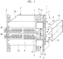
- a plurality of electronic devices 2 such as a server are mounted in a rack 1 of a cabinet type through angles 3 and metal fittings in a height direction. Cables 4 are connected to each electronic device 2 and the cables 4 extend through both sides of the electronic device 2 to be collected in a space on a back face side of the electronic device 2. In order to make it easy to handle cables 4 in the rack 1, side spaces S are provided on both sides of the electronic device 2 in the rack 1.
- the electronic device 2 is generally structured to take in air from a front face F thereof and exhaust air warmed inside the electronic device 2 from a back face B thereof in order to relieve generated heat. Therefore, in the electronic device 2, such a return flow of warmed exhaust air (warm air), which is exhausted from the back face B of the electronic device 2, passes through the side spaces S to sneak to the front face F of the electronic device 2 and taken inside the electronic device 2 again, is generated. In order to prevent such a return flow, heat shutter devices 5 are provided in the side spaces S.
- the heat shutter devices 5 are arranged on both sides of the front faces F of the electronic devices 2.
- the heat shutter devices 5 include a plate-like heat shutter 7 (the same meaning as a heat shutter plate) for blocking the return flow of warm air, which is exhausted from the back face B of the electronic device 2 and passes through the side spaces S to sneak to the front face F of the electronic device 2, with respect to each electronic device 2, a coupling bar 9 provided in the rack 1 via a base portion 8 for coupling the heat shutters 7 to one another, and engagement portions 10 provided in the heat shutters 7, detachably engaged with the coupling bar 9 and pivotally supporting the heat shutters 7.
- a plate-like heat shutter 7 (the same meaning as a heat shutter plate) for blocking the return flow of warm air, which is exhausted from the back face B of the electronic device 2 and passes through the side spaces S to sneak to the front face F of the electronic device 2, with respect to each electronic device 2, a coupling bar 9 provided in the rack 1 via a base portion 8 for coupling the heat shutters 7 to one another,
- the base portion 8 is formed in a rectangular plate shape vertically elongated and having a plurality of times a height of the electronic device 2 (four times in the example shown in FIG. 2 ). As a material of the base portion 8, metal is preferable.
- a base of the base portion 8 is fixed to a frame or a side panel of the rack 1. It is preferable that when the base portion 8 is fixed to the frame of the rack 1, a screw is used as a fixing means, and that when the base portion 8 is fixed to the side panel of the rack 1, a magnet is used as the fixing means.
- the coupling bar 9 includes a metal bar shaft that is circular in section, and the coupling bar 9 is provided on an outer face on a distal end portion of the base portion 8 over a whole length of the base portion 8 in a height direction by fixing means such as welding or screwing. It is preferable for the sake of manufacture that the coupling bar 9 is set to have the same height as that of the base portion 8. Incidentally, the coupling bar 9 may be divided to pieces for respective heat shutters 7.
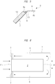
- a clearance groove 11 for avoiding buffering with the engagement portion 10 of the heat shutter 7 is formed in the base portion 8. Further, in order to make attachment of the heat shutter 7 easy, it is preferable that the side of a distal end portion 8a of the base portion 8 is bent outward at a predetermined angle ⁇ to the side of a base 8b of the base portion 8, as shown in FIG. 3 or FIG. 5 .
- the heat shutter 7 is composed of a metal plate having predetermined vertical width fa and lateral width fb so as to cover the side space S from the front face side of the electronic device 2, as shown in FIGS. 4(a) and 4(b) , and FIG. 6 .
- the vertical width fa of the heat shutter 7 is set to have a height of one unit of the electronic devices 2.
- the lateral width fb of the heat shutter 7 is set to have a width between the electronic devices 2 and the frame or the side panel of the rack 1.
- An engagement portion 10 detachably engaged with the coupling bar 9 to pivotally support the heat shutter 7 is provided on one side portion of the heat shutter 7.
- the engagement portion 10 has a vertical width fc narrower than the vertical width fa of the heat shutter 7, and the engagement portion 10 is bent in a U shape in section so as to surround the periphery of the coupling bar 9 between the same (the engagement portion 10) and an elastic member 12.
- the heat shutter 7 has the elastic member 12 closing a gap between the same (the heat shutter 7) and the electronic device 2 in conformity with irregularities of the cables 4 or the like.
- the elastic member 12 is formed in a block shape or in a rectangular-parallelepiped shape having approximately the same size as a plate-like portion of the heat shutter 7 except for the engagement portion 10 and a predetermined thickness.
- the elastic member 12 is composed of flame-retardant sponge.
- the elastic member 12 is attached to an inner face of the heat shutter 7 via adhesive or an adhesive sheet.
- the electronic devices 2 stacked in a height direction include a first electronic device 2a having an intake port (not shown) on a front face thereof and an exhaust port (not shown) on a back face thereof, and a second electronic device 2b having an intake port 13 or an exhaust port on a side face thereof.
- a first electronic device 2a having an intake port (not shown) on a front face thereof and an exhaust port (not shown) on a back face thereof
- a second electronic device 2b having an intake port 13 or an exhaust port on a side face thereof.
- an intake duct 14 or an exhaust duct (not shown) having the intake port 13 or the exhaust port and the front face or the back face of the electronic device 2b communicated with each other is attached to a side face of the second electronic device 2b in the second electronic device 2b in place of the heat shutter 7.
- the intake duct 14 is opened at its inside face 14a and its front end face 14b facing the side wall of the second electronic device 2b, and the exhaust duct is opened at its inside face and its back end face.
- the intake duct 14 or the exhaust duct is attached in such a state that the front end portion of the intake duct 14 or the back end portion of the exhaust duct is fitted in a square opening portion 15 surrounded by the second electronic device 2b, the base portion 8 and the heat shutters 7.
- the heat shutter device 5 structured in the above manner, it becomes possible to adopt a return flow prevention measure depending on an installation situation of the electronic devices 2 regarding the side spaces S inside the rack 1, and the heat shutter device 5 that can achieve improvement of durability of the electronic device 2 while suppressing rising of an intake temperature of the electronic device 2 can be provided.
- the heat shutter 7 is structured so as to be pivotally supported by attaching the elastic member 12, having one unit size of the electronic devices 2 and composed of the flame-retardant sponge, to the back face and hooking the engagement portion 10 on the coupling bar 9 of the base portion 8, an installation angle about the coupling bar 9 of the heat shutter 7 can be adjusted optionally depending on an amount of cables 4 for each unit of the electronic devices 2, and it becomes possible to make a gap between the heat shutter 7 and the electronic device 2 sufficiently small by shrinkage of the elastic member 12 to block a circulation of exhaust air.
- the heat shutter 7 has the engagement portion 10 detachably engaged with the coupling bar 9 to pivotally support the heat shutter 7, attaching and detaching of the heat shutter 7 can be easily performed depending on an installation situation of the electronic device 2, which can result in improvement of workability.
- the intake duct 14 is structured to take in air from the front face side of the rack 1
- the exhaust duct is structured to exhaust air from the back face side of the rack 1
- either one of the intake duct 14 and the exhaust duct can be selected depending on the intake port 13 or the exhaust port arranged on the side face of the electronic device, it becomes possible to cool the electronic device efficiently, thereby achieving achieve improvement of the durability of the electronic device.
- the server rack is used not only in the data center but also in a company server room or the like, when a side space is present in the server rack, it becomes necessary to adopt a return flow prevention measurement of warm air in the side space.
- the present invention can be utilized effectively. Further, since the present invention can be applied to an electronic device performing intake of air and exhaust of air from a side of a network device or the like by replacing the heat shutter with the intake duct or the exhaust duct, a measure depending on an electronic device to be installed can be adopted, and since it becomes possible to cool an electronic device such as a server housed in a server rack efficiently by prevention of a return flow, an effect of energy saving can be obtained. Thus, the present invention can be utilized effectively.
Claims (4)
- Dispositif obturateur de chaleur (5) prévu dans un bâti (1) dans lequel une pluralité de dispositifs électroniques (2) sont montés dans une direction de hauteur de ceux-ci pendant que des espaces latéraux (S) pour câbles (4) sont fixés des deux côtés des dispositifs électroniques (2), le dispositif obturateur de chaleur (5) comprenant :un obturateur de chaleur (7) couvrant l'espace latéral (S) pour câble (4) du côté avant du dispositif électronique (2) et bloquant un flux de retour d'air chaud, qui est évacué d'une face arrière (B) du dispositif électronique et passe à travers les espaces latéraux (S) pour câble (4) pour se faufiler vers une face avant (F) du dispositif électronique (2), par rapport à chaque dispositif électronique ;une barre de couplage (9) prévue dans le bâti (1) dans une direction de hauteur du dispositif électronique via une portion de base (8) ; etune portion de mise en prise (10) prévue sur un côté de l'obturateur de chaleur (7) et mise en prise de manière pivotante avec la barre de couplage (9).
- Dispositif obturateur de chaleur (5) selon la revendication 1,
dans lequel l'obturateur de chaleur (7) a un élément élastique (12) fermant un espace entre l'obturateur de chaleur (7) et le dispositif électronique (2) sur une face arrière de l'obturateur de chaleur (7). - Dispositif obturateur de chaleur (5) selon la revendication 2, dans lequel l'élément élastique (12) est composé d'une éponge ignifuge.
- Dispositif obturateur de chaleur (7) selon la revendication 1, dans lequel la pluralité de dispositifs électroniques (2) montés dans une direction de hauteur de ceux-ci comprennent :- un premier dispositif électronique (2a) ayant un orifice d'admission sur une face avant de celui-ci est un orifice d'évacuation sur une face arrière de celui-ci, et- un deuxième dispositif électronique (2b) ayant un orifice d'admission (13) ou un orifice d'évacuation sur une face latérale de celui-ci,dans lequel un conduit d'admission (14) ou un conduit d'évacuation, dont l'orifice d'admission ou l'orifice d'évacuation et une face avant ou une face arrière du deuxième dispositif électronique (2b) sont en communication l'un avec l'autre, est fixé au deuxième dispositif électronique (2b) à la place de l'obturateur de chaleur (7).
Applications Claiming Priority (1)
| Application Number | Priority Date | Filing Date | Title |
|---|---|---|---|
| PCT/JP2012/082655 WO2014097367A1 (fr) | 2012-12-17 | 2012-12-17 | Dispositif obturateur de chaleur |
Publications (3)
| Publication Number | Publication Date |
|---|---|
| EP2934077A1 EP2934077A1 (fr) | 2015-10-21 |
| EP2934077A4 EP2934077A4 (fr) | 2016-10-19 |
| EP2934077B1 true EP2934077B1 (fr) | 2018-08-15 |
Family
ID=50977756
Family Applications (1)
| Application Number | Title | Priority Date | Filing Date |
|---|---|---|---|
| EP12890312.7A Active EP2934077B1 (fr) | 2012-12-17 | 2012-12-17 | Dispositif obturateur de chaleur |
Country Status (4)
| Country | Link |
|---|---|
| US (1) | US20150334873A1 (fr) |
| EP (1) | EP2934077B1 (fr) |
| JP (1) | JP5974113B2 (fr) |
| WO (1) | WO2014097367A1 (fr) |
Families Citing this family (4)
| Publication number | Priority date | Publication date | Assignee | Title |
|---|---|---|---|---|
| JP6613665B2 (ja) * | 2015-07-10 | 2019-12-04 | 富士通株式会社 | 電子機器 |
| US9801308B2 (en) * | 2016-03-09 | 2017-10-24 | Dell Products Lp | Managing cable connections and air flow in a data center |
| US10433464B1 (en) * | 2016-06-06 | 2019-10-01 | ZT Group Int'l, Inc. | Air duct for cooling a rear-mounted switch in a rack |
| JP7043182B2 (ja) * | 2017-05-15 | 2022-03-29 | 河村電器産業株式会社 | 電気機器収納用キャビネット |
Family Cites Families (34)
| Publication number | Priority date | Publication date | Assignee | Title |
|---|---|---|---|---|
| JPH02187984A (ja) * | 1989-01-13 | 1990-07-24 | Fujitsu Ltd | 磁気ディスク装置 |
| US6788535B2 (en) * | 2002-12-12 | 2004-09-07 | 3M Innovative Properties Company | Outdoor electronic equipment cabinet |
| US7031154B2 (en) * | 2003-04-30 | 2006-04-18 | Hewlett-Packard Development Company, L.P. | Louvered rack |
| US7033267B2 (en) * | 2003-05-13 | 2006-04-25 | American Power Conversion Corporation | Rack enclosure |
| US20050276017A1 (en) * | 2004-06-10 | 2005-12-15 | Farid Aziz | Common plenum and air intake airflow management for telecom equipment |
| JP2006059448A (ja) * | 2004-08-20 | 2006-03-02 | Hitachi Ltd | ディスクアレイ装置 |
| GB2419038B (en) * | 2004-09-23 | 2010-03-31 | Trox | Cooling methods and apparatus |
| US7113401B2 (en) * | 2004-10-25 | 2006-09-26 | International Business Machines Corporation | System for airflow management in electronic enclosures |
| US7804685B2 (en) * | 2005-09-19 | 2010-09-28 | Chatsworth Products, Inc. | Ducted exhaust equipment enclosure |
| JP2007179655A (ja) * | 2005-12-28 | 2007-07-12 | Hitachi Ltd | ディスクアレイ装置 |
| US20070159791A1 (en) * | 2006-01-11 | 2007-07-12 | Lucent Technologies Inc. | Low-profile articulated electronics enclosure with improved air coolant system |
| US8257155B2 (en) * | 2006-01-20 | 2012-09-04 | Chatsworth Products, Inc. | Selectively routing air within an electronic equipment enclosure |
| JP2007305754A (ja) | 2006-05-11 | 2007-11-22 | Kawamura Electric Inc | キャビネットラックのヒートシャッタ構造 |
| US7595985B2 (en) * | 2006-06-19 | 2009-09-29 | Panduit Corp. | Network cabinet with thermal air flow management |
| JP2008117876A (ja) * | 2006-11-02 | 2008-05-22 | Kawamura Electric Inc | 冷気循環システム |
| JP4491451B2 (ja) * | 2006-11-20 | 2010-06-30 | エヌイーシーコンピュータテクノ株式会社 | ラックキャビネット |
| US7564685B2 (en) * | 2006-12-29 | 2009-07-21 | Google Inc. | Motherboards with integrated cooling |
| US7710720B2 (en) * | 2007-01-23 | 2010-05-04 | Fujitsu Limited | Electronic device and fire protecting mechanism of the electronic device |
| JP5030631B2 (ja) * | 2007-03-22 | 2012-09-19 | 富士通株式会社 | 情報機器の冷却システム |
| US8009430B2 (en) * | 2007-05-17 | 2011-08-30 | International Business Machines Corporation | Techniques for data center cooling |
| US7643291B2 (en) * | 2007-08-30 | 2010-01-05 | Afco Systems | Cabinet for electronic equipment |
| US7907402B2 (en) * | 2007-11-09 | 2011-03-15 | Panduit Corp. | Cooling system |
| US20090122483A1 (en) * | 2007-11-13 | 2009-05-14 | International Business Machines Corporation | Water-assisted air cooling for a row of cabinets |
| US20090255653A1 (en) * | 2008-04-11 | 2009-10-15 | Dell Products L.P. | System and Method for Cooling a Rack |
| JP4607203B2 (ja) * | 2008-04-28 | 2011-01-05 | 株式会社日立製作所 | ディスクアレイ装置 |
| US8040693B2 (en) * | 2008-10-02 | 2011-10-18 | Panduit Corp. | Universal expandable patch panel bracket |
| US8081459B2 (en) * | 2008-10-17 | 2011-12-20 | Cray Inc. | Air conditioning systems for computer systems and associated methods |
| WO2011047116A1 (fr) * | 2009-10-14 | 2011-04-21 | Commscope, Inc. Of North Carolina | Armoire de communication extérieure comprenant un plateau de ventilateur et un filtre et des évents résistant aux projectiles, et procédé de détection du colmatage du filtre de l'armoire de communication |
| US8164897B2 (en) * | 2010-02-19 | 2012-04-24 | International Business Machines Corporation | Airflow recirculation and cooling apparatus and method for an electronics rack |
| US8154867B2 (en) * | 2010-03-10 | 2012-04-10 | Ciena Corporation | High density switching platform with interbay connections arrangement |
| US8203837B2 (en) * | 2010-03-31 | 2012-06-19 | Hewlett-Packard Developmet Company, L.P. | Cooling system |
| US9313927B2 (en) * | 2010-11-08 | 2016-04-12 | Chatsworth Products, Inc. | Header panel assembly for preventing air circulation above electronic equipment enclosure |
| US8576570B2 (en) * | 2011-03-21 | 2013-11-05 | NCS Technologies, Inc. | Adaptive computing system with modular control, switching, and power supply architecture |
| JP5201611B2 (ja) * | 2011-05-25 | 2013-06-05 | エヌイーシーコンピュータテクノ株式会社 | 電子機器の冷却構造 |
-
2012
- 2012-12-17 JP JP2014552766A patent/JP5974113B2/ja not_active Expired - Fee Related
- 2012-12-17 EP EP12890312.7A patent/EP2934077B1/fr active Active
- 2012-12-17 WO PCT/JP2012/082655 patent/WO2014097367A1/fr active Application Filing
- 2012-12-17 US US14/652,353 patent/US20150334873A1/en not_active Abandoned
Non-Patent Citations (1)
| Title |
|---|
| None * |
Also Published As
| Publication number | Publication date |
|---|---|
| WO2014097367A1 (fr) | 2014-06-26 |
| EP2934077A4 (fr) | 2016-10-19 |
| JPWO2014097367A1 (ja) | 2017-01-12 |
| EP2934077A1 (fr) | 2015-10-21 |
| US20150334873A1 (en) | 2015-11-19 |
| JP5974113B2 (ja) | 2016-08-23 |
Similar Documents
| Publication | Publication Date | Title |
|---|---|---|
| US9167719B2 (en) | Systems and methods for managing heat generated by electronic equipment in an electronic equipment enclosure | |
| EP2934077B1 (fr) | Dispositif obturateur de chaleur | |
| EP2983461B1 (fr) | Structure d'armoires et conteneur pour centre de données associé | |
| US7894190B2 (en) | Electronic equipment enclosure with side-to-side airflow control system | |
| US8405984B2 (en) | Exhaust air duct with adjustable filler panel assemblies | |
| US7193845B2 (en) | Removable cage for a computer chassis | |
| US20120049706A1 (en) | Air Flow Management Enclosure | |
| US20100238626A1 (en) | Modular Air Management Devices | |
| EP2298051A1 (fr) | Unité de refroidissement montée dans une baie | |
| US8848367B2 (en) | Thermal management system | |
| US20190182989A1 (en) | Adapting frame for rack door | |
| EP2364076B1 (fr) | Armoire pour unités de refroidissement pour salles de serveur | |
| US8142149B2 (en) | Fan device and fan device assembly | |
| RU157202U1 (ru) | Телекоммуникационный шкаф воздушного охлаждения секционированный | |
| JP6182747B2 (ja) | 電気電子機器収納用キャビネット | |
| JP6123083B2 (ja) | 電気電子機器収納用ラック | |
| JP2010168768A (ja) | ラック間通路遮へい構造 | |
| JP2010168769A (ja) | ラック間通路遮へい構造 | |
| JP2009124074A (ja) | 通信装置収容用の密閉筐体 | |
| TW201442590A (zh) | 機櫃式伺服器及虛擬伺服器機箱 | |
| JP7442542B2 (ja) | 電力変換装置 | |
| JP5601690B2 (ja) | 電気機器収納用箱のルーバー構造 | |
| JP5927650B2 (ja) | 電気機器収納用箱 | |
| US20140185237A1 (en) | Opacity Baffle to Prevent Viewing of Internal Structures in Secure Electronic Equipment | |
| CN203225964U (zh) | 机柜顶盖和线缆保护框组件 |
Legal Events
| Date | Code | Title | Description |
|---|---|---|---|
| PUAI | Public reference made under article 153(3) epc to a published international application that has entered the european phase |
Free format text: ORIGINAL CODE: 0009012 |
|
| 17P | Request for examination filed |
Effective date: 20150716 |
|
| AK | Designated contracting states |
Kind code of ref document: A1 Designated state(s): AL AT BE BG CH CY CZ DE DK EE ES FI FR GB GR HR HU IE IS IT LI LT LU LV MC MK MT NL NO PL PT RO RS SE SI SK SM TR |
|
| AX | Request for extension of the european patent |
Extension state: BA ME |
|
| DAX | Request for extension of the european patent (deleted) | ||
| A4 | Supplementary search report drawn up and despatched |
Effective date: 20160920 |
|
| RIC1 | Information provided on ipc code assigned before grant |
Ipc: H05K 7/20 20060101AFI20160914BHEP Ipc: H05K 7/18 20060101ALI20160914BHEP |
|
| GRAP | Despatch of communication of intention to grant a patent |
Free format text: ORIGINAL CODE: EPIDOSNIGR1 |
|
| INTG | Intention to grant announced |
Effective date: 20180302 |
|
| GRAS | Grant fee paid |
Free format text: ORIGINAL CODE: EPIDOSNIGR3 |
|
| GRAA | (expected) grant |
Free format text: ORIGINAL CODE: 0009210 |
|
| AK | Designated contracting states |
Kind code of ref document: B1 Designated state(s): AL AT BE BG CH CY CZ DE DK EE ES FI FR GB GR HR HU IE IS IT LI LT LU LV MC MK MT NL NO PL PT RO RS SE SI SK SM TR |
|
| REG | Reference to a national code |
Ref country code: CH Ref legal event code: EP Ref country code: GB Ref legal event code: FG4D Ref country code: AT Ref legal event code: REF Ref document number: 1031326 Country of ref document: AT Kind code of ref document: T Effective date: 20180815 |
|
| REG | Reference to a national code |
Ref country code: IE Ref legal event code: FG4D |
|
| REG | Reference to a national code |
Ref country code: DE Ref legal event code: R096 Ref document number: 602012049957 Country of ref document: DE |
|
| REG | Reference to a national code |
Ref country code: NL Ref legal event code: MP Effective date: 20180815 |
|
| REG | Reference to a national code |
Ref country code: LT Ref legal event code: MG4D |
|
| REG | Reference to a national code |
Ref country code: AT Ref legal event code: MK05 Ref document number: 1031326 Country of ref document: AT Kind code of ref document: T Effective date: 20180815 |
|
| PG25 | Lapsed in a contracting state [announced via postgrant information from national office to epo] |
Ref country code: GR Free format text: LAPSE BECAUSE OF FAILURE TO SUBMIT A TRANSLATION OF THE DESCRIPTION OR TO PAY THE FEE WITHIN THE PRESCRIBED TIME-LIMIT Effective date: 20181116 Ref country code: BG Free format text: LAPSE BECAUSE OF FAILURE TO SUBMIT A TRANSLATION OF THE DESCRIPTION OR TO PAY THE FEE WITHIN THE PRESCRIBED TIME-LIMIT Effective date: 20181115 Ref country code: SE Free format text: LAPSE BECAUSE OF FAILURE TO SUBMIT A TRANSLATION OF THE DESCRIPTION OR TO PAY THE FEE WITHIN THE PRESCRIBED TIME-LIMIT Effective date: 20180815 Ref country code: NL Free format text: LAPSE BECAUSE OF FAILURE TO SUBMIT A TRANSLATION OF THE DESCRIPTION OR TO PAY THE FEE WITHIN THE PRESCRIBED TIME-LIMIT Effective date: 20180815 Ref country code: RS Free format text: LAPSE BECAUSE OF FAILURE TO SUBMIT A TRANSLATION OF THE DESCRIPTION OR TO PAY THE FEE WITHIN THE PRESCRIBED TIME-LIMIT Effective date: 20180815 Ref country code: NO Free format text: LAPSE BECAUSE OF FAILURE TO SUBMIT A TRANSLATION OF THE DESCRIPTION OR TO PAY THE FEE WITHIN THE PRESCRIBED TIME-LIMIT Effective date: 20181115 Ref country code: AT Free format text: LAPSE BECAUSE OF FAILURE TO SUBMIT A TRANSLATION OF THE DESCRIPTION OR TO PAY THE FEE WITHIN THE PRESCRIBED TIME-LIMIT Effective date: 20180815 Ref country code: IS Free format text: LAPSE BECAUSE OF FAILURE TO SUBMIT A TRANSLATION OF THE DESCRIPTION OR TO PAY THE FEE WITHIN THE PRESCRIBED TIME-LIMIT Effective date: 20181215 Ref country code: FI Free format text: LAPSE BECAUSE OF FAILURE TO SUBMIT A TRANSLATION OF THE DESCRIPTION OR TO PAY THE FEE WITHIN THE PRESCRIBED TIME-LIMIT Effective date: 20180815 Ref country code: LT Free format text: LAPSE BECAUSE OF FAILURE TO SUBMIT A TRANSLATION OF THE DESCRIPTION OR TO PAY THE FEE WITHIN THE PRESCRIBED TIME-LIMIT Effective date: 20180815 |
|
| PG25 | Lapsed in a contracting state [announced via postgrant information from national office to epo] |
Ref country code: AL Free format text: LAPSE BECAUSE OF FAILURE TO SUBMIT A TRANSLATION OF THE DESCRIPTION OR TO PAY THE FEE WITHIN THE PRESCRIBED TIME-LIMIT Effective date: 20180815 Ref country code: LV Free format text: LAPSE BECAUSE OF FAILURE TO SUBMIT A TRANSLATION OF THE DESCRIPTION OR TO PAY THE FEE WITHIN THE PRESCRIBED TIME-LIMIT Effective date: 20180815 Ref country code: HR Free format text: LAPSE BECAUSE OF FAILURE TO SUBMIT A TRANSLATION OF THE DESCRIPTION OR TO PAY THE FEE WITHIN THE PRESCRIBED TIME-LIMIT Effective date: 20180815 |
|
| PG25 | Lapsed in a contracting state [announced via postgrant information from national office to epo] |
Ref country code: PL Free format text: LAPSE BECAUSE OF FAILURE TO SUBMIT A TRANSLATION OF THE DESCRIPTION OR TO PAY THE FEE WITHIN THE PRESCRIBED TIME-LIMIT Effective date: 20180815 Ref country code: ES Free format text: LAPSE BECAUSE OF FAILURE TO SUBMIT A TRANSLATION OF THE DESCRIPTION OR TO PAY THE FEE WITHIN THE PRESCRIBED TIME-LIMIT Effective date: 20180815 Ref country code: CZ Free format text: LAPSE BECAUSE OF FAILURE TO SUBMIT A TRANSLATION OF THE DESCRIPTION OR TO PAY THE FEE WITHIN THE PRESCRIBED TIME-LIMIT Effective date: 20180815 Ref country code: RO Free format text: LAPSE BECAUSE OF FAILURE TO SUBMIT A TRANSLATION OF THE DESCRIPTION OR TO PAY THE FEE WITHIN THE PRESCRIBED TIME-LIMIT Effective date: 20180815 Ref country code: EE Free format text: LAPSE BECAUSE OF FAILURE TO SUBMIT A TRANSLATION OF THE DESCRIPTION OR TO PAY THE FEE WITHIN THE PRESCRIBED TIME-LIMIT Effective date: 20180815 |
|
| REG | Reference to a national code |
Ref country code: DE Ref legal event code: R097 Ref document number: 602012049957 Country of ref document: DE |
|
| PG25 | Lapsed in a contracting state [announced via postgrant information from national office to epo] |
Ref country code: SK Free format text: LAPSE BECAUSE OF FAILURE TO SUBMIT A TRANSLATION OF THE DESCRIPTION OR TO PAY THE FEE WITHIN THE PRESCRIBED TIME-LIMIT Effective date: 20180815 Ref country code: SM Free format text: LAPSE BECAUSE OF FAILURE TO SUBMIT A TRANSLATION OF THE DESCRIPTION OR TO PAY THE FEE WITHIN THE PRESCRIBED TIME-LIMIT Effective date: 20180815 Ref country code: DK Free format text: LAPSE BECAUSE OF FAILURE TO SUBMIT A TRANSLATION OF THE DESCRIPTION OR TO PAY THE FEE WITHIN THE PRESCRIBED TIME-LIMIT Effective date: 20180815 |
|
| PLBE | No opposition filed within time limit |
Free format text: ORIGINAL CODE: 0009261 |
|
| STAA | Information on the status of an ep patent application or granted ep patent |
Free format text: STATUS: NO OPPOSITION FILED WITHIN TIME LIMIT |
|
| 26N | No opposition filed |
Effective date: 20190516 |
|
| REG | Reference to a national code |
Ref country code: CH Ref legal event code: PL |
|
| PG25 | Lapsed in a contracting state [announced via postgrant information from national office to epo] |
Ref country code: MC Free format text: LAPSE BECAUSE OF FAILURE TO SUBMIT A TRANSLATION OF THE DESCRIPTION OR TO PAY THE FEE WITHIN THE PRESCRIBED TIME-LIMIT Effective date: 20180815 Ref country code: SI Free format text: LAPSE BECAUSE OF FAILURE TO SUBMIT A TRANSLATION OF THE DESCRIPTION OR TO PAY THE FEE WITHIN THE PRESCRIBED TIME-LIMIT Effective date: 20180815 Ref country code: LU Free format text: LAPSE BECAUSE OF NON-PAYMENT OF DUE FEES Effective date: 20181217 |
|
| REG | Reference to a national code |
Ref country code: IE Ref legal event code: MM4A |
|
| REG | Reference to a national code |
Ref country code: BE Ref legal event code: MM Effective date: 20181231 |
|
| PG25 | Lapsed in a contracting state [announced via postgrant information from national office to epo] |
Ref country code: IE Free format text: LAPSE BECAUSE OF NON-PAYMENT OF DUE FEES Effective date: 20181217 Ref country code: FR Free format text: LAPSE BECAUSE OF NON-PAYMENT OF DUE FEES Effective date: 20181231 |
|
| PG25 | Lapsed in a contracting state [announced via postgrant information from national office to epo] |
Ref country code: BE Free format text: LAPSE BECAUSE OF NON-PAYMENT OF DUE FEES Effective date: 20181231 |
|
| PG25 | Lapsed in a contracting state [announced via postgrant information from national office to epo] |
Ref country code: LI Free format text: LAPSE BECAUSE OF NON-PAYMENT OF DUE FEES Effective date: 20181231 Ref country code: CH Free format text: LAPSE BECAUSE OF NON-PAYMENT OF DUE FEES Effective date: 20181231 |
|
| PG25 | Lapsed in a contracting state [announced via postgrant information from national office to epo] |
Ref country code: MT Free format text: LAPSE BECAUSE OF NON-PAYMENT OF DUE FEES Effective date: 20181217 |
|
| PG25 | Lapsed in a contracting state [announced via postgrant information from national office to epo] |
Ref country code: TR Free format text: LAPSE BECAUSE OF FAILURE TO SUBMIT A TRANSLATION OF THE DESCRIPTION OR TO PAY THE FEE WITHIN THE PRESCRIBED TIME-LIMIT Effective date: 20180815 |
|
| PG25 | Lapsed in a contracting state [announced via postgrant information from national office to epo] |
Ref country code: PT Free format text: LAPSE BECAUSE OF FAILURE TO SUBMIT A TRANSLATION OF THE DESCRIPTION OR TO PAY THE FEE WITHIN THE PRESCRIBED TIME-LIMIT Effective date: 20180815 |
|
| PG25 | Lapsed in a contracting state [announced via postgrant information from national office to epo] |
Ref country code: CY Free format text: LAPSE BECAUSE OF FAILURE TO SUBMIT A TRANSLATION OF THE DESCRIPTION OR TO PAY THE FEE WITHIN THE PRESCRIBED TIME-LIMIT Effective date: 20180815 Ref country code: HU Free format text: LAPSE BECAUSE OF FAILURE TO SUBMIT A TRANSLATION OF THE DESCRIPTION OR TO PAY THE FEE WITHIN THE PRESCRIBED TIME-LIMIT; INVALID AB INITIO Effective date: 20121217 Ref country code: MK Free format text: LAPSE BECAUSE OF NON-PAYMENT OF DUE FEES Effective date: 20180815 |
|
| PGFP | Annual fee paid to national office [announced via postgrant information from national office to epo] |
Ref country code: GB Payment date: 20231220 Year of fee payment: 12 |
|
| PGFP | Annual fee paid to national office [announced via postgrant information from national office to epo] |
Ref country code: IT Payment date: 20231205 Year of fee payment: 12 Ref country code: DE Payment date: 20231214 Year of fee payment: 12 |