EP2934050B1 - Dispositif et procédé de fourniture de connexion - Google Patents
Dispositif et procédé de fourniture de connexion Download PDFInfo
- Publication number
- EP2934050B1 EP2934050B1 EP15170199.2A EP15170199A EP2934050B1 EP 2934050 B1 EP2934050 B1 EP 2934050B1 EP 15170199 A EP15170199 A EP 15170199A EP 2934050 B1 EP2934050 B1 EP 2934050B1
- Authority
- EP
- European Patent Office
- Prior art keywords
- sgsn
- identifier
- network
- rnc
- network element
- Prior art date
- Legal status (The legal status is an assumption and is not a legal conclusion. Google has not performed a legal analysis and makes no representation as to the accuracy of the status listed.)
- Revoked
Links
Images


Classifications
-
- H—ELECTRICITY
- H04—ELECTRIC COMMUNICATION TECHNIQUE
- H04W—WIRELESS COMMUNICATION NETWORKS
- H04W48/00—Access restriction; Network selection; Access point selection
- H04W48/08—Access restriction or access information delivery, e.g. discovery data delivery
-
- H—ELECTRICITY
- H04—ELECTRIC COMMUNICATION TECHNIQUE
- H04W—WIRELESS COMMUNICATION NETWORKS
- H04W60/00—Affiliation to network, e.g. registration; Terminating affiliation with the network, e.g. de-registration
- H04W60/04—Affiliation to network, e.g. registration; Terminating affiliation with the network, e.g. de-registration using triggered events
-
- H—ELECTRICITY
- H04—ELECTRIC COMMUNICATION TECHNIQUE
- H04L—TRANSMISSION OF DIGITAL INFORMATION, e.g. TELEGRAPHIC COMMUNICATION
- H04L61/00—Network arrangements, protocols or services for addressing or naming
-
- H—ELECTRICITY
- H04—ELECTRIC COMMUNICATION TECHNIQUE
- H04L—TRANSMISSION OF DIGITAL INFORMATION, e.g. TELEGRAPHIC COMMUNICATION
- H04L61/00—Network arrangements, protocols or services for addressing or naming
- H04L61/45—Network directories; Name-to-address mapping
-
- H—ELECTRICITY
- H04—ELECTRIC COMMUNICATION TECHNIQUE
- H04L—TRANSMISSION OF DIGITAL INFORMATION, e.g. TELEGRAPHIC COMMUNICATION
- H04L67/00—Network arrangements or protocols for supporting network services or applications
- H04L67/01—Protocols
- H04L67/10—Protocols in which an application is distributed across nodes in the network
- H04L67/1001—Protocols in which an application is distributed across nodes in the network for accessing one among a plurality of replicated servers
- H04L67/1004—Server selection for load balancing
- H04L67/1008—Server selection for load balancing based on parameters of servers, e.g. available memory or workload
-
- H—ELECTRICITY
- H04—ELECTRIC COMMUNICATION TECHNIQUE
- H04L—TRANSMISSION OF DIGITAL INFORMATION, e.g. TELEGRAPHIC COMMUNICATION
- H04L67/00—Network arrangements or protocols for supporting network services or applications
- H04L67/01—Protocols
- H04L67/10—Protocols in which an application is distributed across nodes in the network
- H04L67/1001—Protocols in which an application is distributed across nodes in the network for accessing one among a plurality of replicated servers
- H04L67/1004—Server selection for load balancing
- H04L67/1019—Random or heuristic server selection
-
- H—ELECTRICITY
- H04—ELECTRIC COMMUNICATION TECHNIQUE
- H04L—TRANSMISSION OF DIGITAL INFORMATION, e.g. TELEGRAPHIC COMMUNICATION
- H04L67/00—Network arrangements or protocols for supporting network services or applications
- H04L67/01—Protocols
- H04L67/10—Protocols in which an application is distributed across nodes in the network
- H04L67/1001—Protocols in which an application is distributed across nodes in the network for accessing one among a plurality of replicated servers
- H04L67/1004—Server selection for load balancing
- H04L67/1021—Server selection for load balancing based on client or server locations
-
- H—ELECTRICITY
- H04—ELECTRIC COMMUNICATION TECHNIQUE
- H04L—TRANSMISSION OF DIGITAL INFORMATION, e.g. TELEGRAPHIC COMMUNICATION
- H04L67/00—Network arrangements or protocols for supporting network services or applications
- H04L67/01—Protocols
- H04L67/10—Protocols in which an application is distributed across nodes in the network
- H04L67/1001—Protocols in which an application is distributed across nodes in the network for accessing one among a plurality of replicated servers
- H04L67/1029—Protocols in which an application is distributed across nodes in the network for accessing one among a plurality of replicated servers using data related to the state of servers by a load balancer
-
- H—ELECTRICITY
- H04—ELECTRIC COMMUNICATION TECHNIQUE
- H04L—TRANSMISSION OF DIGITAL INFORMATION, e.g. TELEGRAPHIC COMMUNICATION
- H04L67/00—Network arrangements or protocols for supporting network services or applications
- H04L67/14—Session management
-
- H—ELECTRICITY
- H04—ELECTRIC COMMUNICATION TECHNIQUE
- H04W—WIRELESS COMMUNICATION NETWORKS
- H04W48/00—Access restriction; Network selection; Access point selection
- H04W48/18—Selecting a network or a communication service
-
- H—ELECTRICITY
- H04—ELECTRIC COMMUNICATION TECHNIQUE
- H04W—WIRELESS COMMUNICATION NETWORKS
- H04W76/00—Connection management
- H04W76/20—Manipulation of established connections
Definitions
- the present invention relates to devices, system and method e.g. for providing a connection e.g. in a communication network.
- the communication network may be a pure data network, a network for transmitting data and/or other type of information such as speech or may be a network exclusively reserved for non-data information.
- the network can be a circuit-switched network, a packet-switched network such as a GPRS or UMTS network, or may consist of a combination of networks of different type.
- connection originating network element When providing a connection in a communication network, usually several network elements are involved, including the connection originating network element, the connection terminating network element and/or one or more intermediate network elements such as a base station, a base transceiver station, a base station controller and/or one or more support nodes handling the signalling and/or user traffic.
- intermediate network elements such as a base station, a base transceiver station, a base station controller and/or one or more support nodes handling the signalling and/or user traffic.
- a connection e.g. call
- a user equipment such as a mobile station (MS)
- a connection terminating or originating equipment using a radio network controller (RNC) which communicates with a SGSN (serving GPRS support node) and possibly a GGSN (gateway GPRS support node).
- RNC radio network controller
- the connection terminating or originating equipment can be located in the same or a different network.
- the actual location thereof is defined with a resolution of a routing area (e.g. in idle state) or with a finer resolution of a cell (e.g. when handling a connection such as a call).
- routing area is a standard term used in conjunction with GPRS, while GSM and UMTS Circuit Switched systems use the term location area (LA).
- LA location area
- the area is referring to the area where a mobile station is registered in the serving node (e.g. SGSN or MSC/VLR), and where eventually the serving node pages the mobile station to establish downlink connection.
- the serving node e.g. SGSN or MSC/VLR
- the term area will be used to refer to location area and/or routing area.
- the coverage area of an entire network is usually divided in several areas (RA or LA), with one area (in a GPRS-or UMTS-based network) being assigned to one serving node (one serving node typically handling many areas).
- RA or LA a GPRS-or UMTS-based network
- serving node one serving node typically handling many areas.
- this one to one correlation between the routing or location areas and the assigned SGSNs may, however, be of disadvantage in case of break-down of an SGSN or necessary maintenance operations such as software updating. In such a case, the routing area has to be completely shut-down and is at least temporarily no longer usable for providing connections.
- BSC base station controller
- RNC radio network controller
- Iu and/or Gb interfaces
- Several types of mobile stations may be supported by using two radio interfaces and providing only one single base transceiver station (BTS).
- the provision of two or more support nodes serving the same routing area provides several advantages such as resilience by enabling an RNC (possibly having a list of available SGSNs) to use another SGSN if the previously used SGSN should become overloaded or out of order. Furthermore, maintenance operations such as software updates can be effected without shutting down the area. In addition, the network signalling caused by inter-SGSN hand-over can be reduced.
- SGSNs may be provided for covering a metropolitan area such as London area, and a mobile station moving around the city can always use its original SGSN for handling connections.
- an IP network may be introduced on an interface such as Iu interface which presently is mainly used as a point-to-point Iu interface between the RNC and the SGSN.
- Iu interface which presently is mainly used as a point-to-point Iu interface between the RNC and the SGSN.
- one RNC may be connected to several SGSNs.
- one network element which e.g. is in charge of controlling the radio connection to a user equipment
- This signalling connection may e.g. be used to transfer L3 (layer 3) messages (such as mobility management MM and session management SM) between the user equipment (e.g. MS) and the support nodes such as SGSN.
- L3 layer 3
- MS mobility management MM
- session management SM session management SM
- WO 99/66742 A1 discloses a method for the control of communication and a communication system, in which a terminal device (MS) communicates with the opposite end via an access network (RAN), using low level signalling protocols, and via a core network connected to the access network, the core network using high level signalling protocols, whereby one or more core networks are connected to the access network (RAN), each core network connected to the access network (RAN) being given a separate identifier and this identifier being used for routing protocol data units (PDU) of a high level signalling protocol.
- RAN access network
- PDU protocol data units
- the present invention provides a solution for solving or at least relieving the above problems either partly or entirely.
- an area identifier such as "Routing Area Identity (RAI)" may be used by the first network element (e.g. RNC) to derive a list of alternatively selectable second network elements such as support nodes. In this list different support nodes are identified by their addresses. This list may be preconfigured inside the RNC.
- the first network element may send a message or request containing the identifier (e.g. RAI) to another network element such as a DNS (Domain Name System) server in order to receive, as a response, a list of possible second network elements serving the routing area indicated by the RAI. This avoids the need of preconfigured list, and DNS is particularly suitable if the list of possible second network elements contains IP addresses.
- the another network element may contain, or co-operate with, a memory storing the list (table) of possible second network elements, and may send this list as a rolling or distributed list to spread the load.
- the list may for instance be sent in form of several parts, each part indicating only one or two (or more) selectable second network elements.
- the list may be ranked in a defined order, for instance based on the address of the first network element sending the list request or indicating first a default second network element for this area. The ranking may be such that the first of the second network elements indicated in the list is always the closest one to the first network element, the second of the listed second network elements being the second closest one to the first network element, etc.
- the order of listing of the second network elements in the list may also, in an embodiment, be based on information on the actual or previous load of each listed second network element.
- the order of listing of the second network elements may be kept unchanged, but additional information is attached to the list indicating the actual or previous load condition of the listed second network elements.
- the first network element is adapted to check the load condition information as well, and to select one of the second network elements having the smallest load or at least being one of the lighter-loaded second network elements.
- the modification of the order of the listing of the second network elements taking account of the load, or the attachment of the load information to the list, may be performed by the operation and maintenance system (O&M) provided for the network.
- O&M operation and maintenance system
- a second network element for which a maintenance operation such as software updating is planned may be withdrawn from the list (to be sent to an inquiring first network element) some time such as a few hours before the software update. In such a way, one can ensure that no or at least not many connections or contexts will still be handled by this second network element.
- another second network element may be selected from the list.
- the identifier such as CN (Core Network) Identifier may be added to a message, e.g. RRC (Radio Resource Control) message which is used to initiate a connection.
- the first network element e.g. RNC
- checks the identifier e.g. CN Identifier
- the first network element may also be adapted to deduce the area identifier such as RAI from the cell where the user equipment is actually located.
- the combination of area identifier and CN Identifier identifies unambiguously the serving node.
- the first network element derives the serving node address from a list.
- the first network element uses the area identifier and/or the CN identifier to request the list-transmitting network element such as a DNS server to send a list of second network elements assigned to the transmitted identifier.
- GSM Global System for Mobile communications
- UMTS UMTS
- the RRC signalling contains a parameter (CN domain identity) identifying the CN type.
- the CN type is identified implicitly from the type of channel established.
- the indication of CN type in addition to the combination of area identifier and CN Identifier may be needed to identify unambiguously the serving node.
- one of the second network elements may be set as a default second network element serving the routing area in which the connection terminating or originating equipment such as MS is presently located.
- the first network element will be configured to use this default second network element for handling a connection as long as no other second network element is selected (i.e. CN identifier is not sent by the MS) .
- the selection of one of the available second network elements covering a certain routing area may be performed in dependence on information coming from other network element such as a user equipment, for instance a mobile station.
- a connection e.g. a signalling connection
- the user equipment may be adapted to send additional information such as CN identifier to e.g. the first network element which may be a RNC.
- the user equipment had established a signalling connection to a certain support node, e.g. SGSN, whereafter the signalling connection had been released, and the user equipment wants to establish the signalling connection again to the same support node.
- the user equipment may then add an identifier information such as CN identifier to a message which, e.g., may be used to carry an L3 message (e.g. a Routing Area Update Request or Service Request).
- L3 message e.g. a Routing Area Update Request or Service Request.
- RNC will select a new serving node, and the new serving node will be able to derive the old serving node address by using the combination of CN identifier (added according to this embodiment to Routing Area Update Request) and old RAI (sent in Routing Area Update Request in GSM and UMTS).
- the first network element e.g. RNC
- the new serving node should send its CN identifier in e.g. Routing Area Update accept, or attach accept to the MS.
- Embodiments of the invention furthermore provide a possibility of finding and selecting an old support node (e.g. old SGSN) by a new support node, in particular after inter-node hand-over.
- an old support node e.g. old SGSN
- a new support node in particular after inter-node hand-over.
- the old SGSN can be found with the old RAI (when only one SGSN serves a specific routing area designated by RAI)
- the new support node is able to detect the old support node in order to e.g. copy context information for handling the connection such as PDP (Packet Data Protocol) context information.
- PDP Packet Data Protocol
- the network element storing the list of second network elements may additionally store, for each support node, a CN identifier identifying this support node.
- This identifier may be sent as a new Information Element (i.e. it is sent explicitly) or may be coded as part of another Information Element such as a temporary identity (i.e. it is sent implicitly).
- CN identifier may be formed by some bits (e.g. 4 last bits) of PTMSI (Packet Temporary Mobile Station Identity).
- the network element storing the list of second network elements available for the respective areas can be a DNS server, and preferably stores the list of support nodes mapped to the respective area indicators such as RAIs (routing area identities) or LAIs (location area identities).
- This network element may return, in response to an area indicator sent to it, not only the IP addresses of every support node (second network element) assigned to the respective area (e.g. RAI), but additionally also the network element identifiers assigned to these support nodes, and eventually the type of support node.
- the network element in charge of selecting the second network element for handling the connection (e.g. signalling connection) may then select that second network element which has an network element identifier corresponding to the network element identifier transmitted e.g. from the user equipment as selection criterion.
- the network element storing the list may be queried with both CN identifier and area identifier, so that only the address of the right support node is returned.
- the type of support node may be used e.g. in a network comporting both 2G and 3G SGSN.
- a RNC (3G only) may only select a support node indicated as a 3G support node, based on the type of support node indicated.
- the second network element may preferably maintain state information about the user equipment (e.g. location, subscriber data, etc.).
- the state information allows keeping the connection to the same serving node, e.g. same SGSN. Without state information, the user equipment might change the serving node, e.g. SGSN, at every connection.
- connection may be maintained in the same selectable second network elements when the MS is moving inside the CN area.
- one of the second network elements available for a routing area may be a master network element which, if not handling itself the context information such as PDP context, may act as a relay, and may determine the old second network element based on e.g. the identifier sent for instance from the user equipment together with PTMSI.
- the identifier may have been sent from the old support node to the user equipment together with PTMSI during (e.g. at the beginning or end) of the time period during which it was in charge for handling the connection to the user equipment.
- the user equipment hence knows the supporting network element such as the support node which handled its connections. This embodiment may be particularly applicable if the SGSN where the MS moved was not upgraded to find the appropriate old (i.e. previous) SGSN.
- the second network elements may also be MSCs (mobile switching centres) or other types of serving elements, e.g. in circuit-switched networks.
- MSCs mobile switching centres
- serving elements e.g. in circuit-switched networks.
- the solutions provided by embodiments of the present invention are furthermore applicable in a case where network elements of different generation (such as 2G SGSN and a 3G SGSN) are provided which handle the connections for the same routing area.
- the selection of the support node may be made depending on the type of the connection established and/or requested, or on the type of the user equipment.
- the invention may be employed in a GERAN system (GSM/EDGE radio access network).
- Embodiments of the present invention allow an effective adaptation of a cellular network being at least partly IP-based.
- IP networks are essentially peer-to-peer structured whereas the conventional cellular networks such as GSM, UMTS, etc. are typically based on an hierarchical architecture wherein a radio access network (RAN) or, in more detail, a controller controlling the radio access such as a RNC, RNS, BTS, BSS and the like, is handled by a single serving node (e.g. MSC/VLR; SGSN;).
- At least one embodiment of the invention generally provides a structure and method wherein one network element providing e.g. radio access (e.g. radio access network, RAN) to a user equipment is connected to many serving nodes such as core network (CN) nodes.
- CN core network
- the invention hence proposes a new architecture for a cellular system wherein one radio access network (or the network element providing or controlling the radio access) as well as a location area (LA) or routing area (RA) can be handled by many serving nodes of the same type.
- a routing function for deciding to which serving node the connection is to be made is preferably located in the radio access network (RAN) or the respective network element providing or controlling the radio access, and is not located between the radio access network and the serving node, or in the serving node.
- the routing function located in the RAN additionally provides or comprises a method for selection of the serving node to connect to.
- the method and system according to embodiments not forming part of the invention may be used to detect the node where a user equipment is actually registered, one of the network elements having a list of serving nodes serving the present location area (or routing area) of the user equipment.
- This list may include a default serving node.
- the serving node to be used for handling the connection may be determined in the following manner: When the user equipment has not sent an identifier such as a core network (CN) identifier, the default serving node, if defined, will be selected from the list. If the user equipment has sent an identifier such as a CN identifier, a serving node corresponding to this identifier will be selected.
- CN core network
- the default serving node may be defined to be the serving node mentioned on a specific position of the list for the routing or location area, e.g. the first serving node mentioned on the list.
- the serving node mentioned on the specific place e.g. the first-mentioned serving node, is selected by the RAN from the list.
- This method and structure can be used by the radio access network (or RAN controlling node or component) to find the serving node to be used. Likewise, this method and structure can be used by the new serving node to find the old serving node to which the user equipment was registered, or may be used by the new serving node to find the MSC/VLR to which the user equipment was registered, in particular in a case when the Gs interface is used.
- a user equipment such as a MS may be adapted to select a serving node by using a CN identifier.
- the CN identifier may be the latest used identifier, or may be a preconfigured, i.e. predetermined CN identifier which is stored in the user equipment, e.g. on a subscriber identity module, SIM, card thereof.
- the method and system according to embodiments of the invention may be used to allow many operators (each owning their own serving node) to share a common Radio Access Network (owned by another operator). If every operator uses a different CN identifier, and if the MSs are configured to always use same CN identifier (even in the very first attach request) based on subscription information typically read from a SIM card, then the MS may always be connected to an SGSN owned by this operator (from which they bought SIM card).
- Fig. 1 shows the basic structure of an embodiment of a system in accordance with the invention.
- the system is implemented as a network 1, or forms a part thereof, which network 1 comprises at least one, or usually a plurality of, user equipments 2 which, in this embodiment, are implemented as mobile stations MS.
- the user equipments may also be any other type of equipments such as stationary terminals. Although only one user equipment 2 is shown, usually several user equipments are attached to the network 1 and represent connection originating or terminating equipments.
- a radio connection to user equipment 2 is provided and handled by a radio access network (RAN).
- the RAN comprises, in this embodiment, a radio network controller (RNC) 3 which is part of, or represents, the radio access network for radio connection to user equipment 2.
- RNC radio network controller
- the RNC 3 first network element
- the network may comprise additional or alternative serving nodes such as mobile switching centres (MSCs) which normally will be combined with visitor location registers (VLRs).
- MSCs mobile switching centres
- VLRs visitor location registers
- the serving nodes 4, 6 may be connected, if necessary, to a gateway node 5 which here is a GGSN and provides the possibility of connection to other networks.
- a DNS (Domain Name System) server 7 is provided which may form part of network 1 or may be a network-external component.
- the DNS server 7 can be accessed by RNC 3, and usually also by other network components such as serving nodes 4, 6 and/or gateway node 5.
- the communication possibilities are shown in Fig. 1 as double-headed arrows.
- the DNS server 7 comprises, or has access possibility to, a memory (not shown) storing lists (tables) of serving nodes available for alternatively covering routing areas or location areas of the network 1.
- Fig. 5 shows an example of a table stored in the memory.
- the table contains several columns and rows.
- the left column "SGSN" lists the available serving nodes.
- SGSN1 may correspond to SGSN 4
- SGSN2 may correspond to SGSN 6,
- SGSN3, SGSN4 may correspond to further serving nodes not shown in Fig. 1 and covering other routing or location areas of the network 1.
- the table furthermore, contains a column "IP address of SGSN" listing the IP addresses of the individual available serving nodes.
- the column "SGSN name" or "(SGSN identifier)" lists the identifiers identifying the individual serving nodes. In this example, the type of the node (2G or 3G) is built in the identifier.
- the column "Routing Area” lists the routing areas or location areas being covered by the individual serving nodes.
- the serving nodes SGSN1 SGSN2, SGSN3 and SGSN4 are available for covering the same first routing area RA1 whereas the serving nodes SGSN1 SGSN2, SGSN3 and SGSN5 are available for alternatively covering a second routing area RA2 in which a mobile station may be located, e.g. after moving thereto from routing area RA1.
- the stored list does not necessarily contain all columns shown in Fig. 5 .
- the column " SGSN" and/or "Routing area” (if all RAs handled by RNC use same CN identifier, and the list is specific per RNC) may be omitted.
- the list may also contain additional information useful for selecting an appropriate serving node. For instance, a column "serving node type" and/or a column indicating default nodes for some or all respective areas may be added.
- the architecture of a network or system comprises two or more CN (core network) nodes of same type (e.g. MSC and/or SGSN) which are connected to the same radio access network or node RAN (e.g. BSS "base station sub-system”; UTRAN “UMTS Terrestrial Radio Access Network”; GERAN “GSM/EDGE Radio Access Network”) and assigned to the same location area (LA) and/or routing area (RA).
- RAN e.g. BSS "base station sub-system”; UTRAN “UMTS Terrestrial Radio Access Network”; GERAN “GSM/EDGE Radio Access Network
- LA location area
- RA routing area
- One or more of the provided RANs contain, or are able to download from a network element such as the DNS server 7, a preconfigured list of CN nodes.
- the CN nodes may be associated with a CN identifier which is unique at least for the assigned LA/RA.
- the system and method according to embodiments of the invention may be structured in such a manner that each time when a user equipment registers into one location or routing area (e.g. by performing an Attach or Area Update procedure), the CN node handling the registration returns its CN identifier to the user equipment, e.g. in the MM (Mobility Management) signalling.
- the user equipment is adapted to store a received CN identifier representing the serving node actually handling a connection.
- the user equipment may be designed to indicate the CN identifier (if known and/or if a re-establishment of the connection to a previously used CN is desired), if desired, when the user equipment establishes a connection to the radio network.
- the CN identifier may be indicated for instance in the radio signalling, e.g. during RRC connection establishment.
- the new information element (identifier such as CN identifier) is an optional information element transmitted in both MM and RRC signalling (if an explicit information element is used for both protocols). This ensures that user equipments not supporting this feature will nevertheless work with new network elements.
- a user equipment is never sending the CN identifier, it is always connected to a CN node which is set as a default node to be selected when not receiving any CN identifier.
- the RNC is structured to ignore any CN identifier and to establish the connection always with the only CN node it is connected with.
- the CN node does not support this feature, no CN identifier will be returned to the user equipment.
- the user equipment may be configured to erase previously stored CN identifier, so that next time it is connected to the default node. In such a case, the user equipment is unable to transmit any CN identifier in the next connection request and will thus be connected to the default CN node provided for this area. In all these cases, the result is similar to existing systems.
- one CN node is not supporting this feature, it shall be configured as the default CN node.
- the TLLI Temporal Logical Link Identifier
- a heavy radio load would result as the CN identifier would have to be sent with every packet transfer as well.
- the CN identifier will be sent implicitly, i.e. encoded within the TLLI. It should be noted that TLLI is always derived from PTMSI, by changing the three first bits.
- This coding may be effected by coding the temporary identity (PTMSI and TLLI) in a defined way, for instance using the 4 last bits to indicate CN identifier.
- This solution does neither increase the radio nor the signalling load.
- the user equipment When sending a Routing Area Update (RAU) and/or Attach Request message, the user equipment automatically sends the old TLLI.
- the new PTMSI coded so as to contain the CN identifier of the serving network element serving the connection, is sent back in the RAU/Attach response message on the radio signalling level.
- RAU Routing Area Update
- Attach Request message the user equipment automatically sends the old TLLI.
- the new PTMSI coded so as to contain the CN identifier of the serving network element serving the connection is sent back in the RAU/Attach response message on the radio signalling level.
- this feature of transmitting a CN identifier can be introduced to a GPRS-based network without changes of the protocols. But it requires
- the above solution is likewise applicable, but would require the RNC to read the PTMSI sent in L3 MM messages, which are presently only relayed by RNC.
- RNC it is possible to introduce a new information element (i.e. to send CN identifier explicitly) for identifying the serving node in charge of the connection to the user equipment.
- the RNC keeps the RRC context. Therefore, when including the CN identifier into the RRC context, it is not necessary to send the CN identifier often.
- the user equipment may include the CN identifier in the RA (routing area) update request message, and the DNS server 5 may return, upon a respective query from the RNC 3 indicating the old routing area identifier, a list of IP addresses of SGSNs in charge of the routing area.
- a CN identifier is implicitly or explicitly associated with every IP address, such as shown in Fig. 5 .
- the CN identifier is implicitly indicated if the position on the list indicates the CN identifier. In such a case, it is not necessary to separately transmit the CN (e.g. SGSN) identifier.
- the routing area identifier designates the routing area RA 1
- a list is returned from DNS server 7 to RNC 3 containing SGSN1 and SGSN2 and indicating the IP addresses thereof.
- the associated identifiers "2G_SGSN IDENTIFIER_13" and “3G_SGSN IDENTIFIER_14" are transmitted associated with the IP addresses.
- the Canonical name associated with the IP address is returned from DNS server 7 to RNC 3 which represents the value of the CN identifier.
- This concept effectively uses the structure of DNS which is based on Canonical name (CNAME) or alias, as defined in e.g. RFC 1034 and 1035. Therefore, as part of the response of the DNS, there is a transmitted a list of IP addresses and Canonical names (CNAME), as indicated in Fig. 5 by the two center columns and the rows associated to the same routing area (e.g. RA1), respectively.
- the RNC or BSC can easily select the appropriate SGSN on the basis of the technology used by the user equipment and of the SGSN identifier, which can be recognised from e.g. TLLI in GPRS, and extended CN identifier in UMTS, as mentioned above.
- the CN identifier When the CN identifier is only implicitly indicated, it is represented by the position on the list. For instance, when not sending the SGSN NAME identifier, the first SGSN1 is determined as the SGSN to be used for handling the connection of the user equipment in routing area 1, This SGSN thus serves e.g. as a default serving node to be used for connection handling when no CN identifier (SGSN identifier) is indicated.
- the SGSN having an assigned CN identifier which corresponds to the CN identifier indicated by user equipment 2 will be selected as SGSN for handling the connection, or for transmitting the context information to the new SGSN.
- the new SGSN can detect the old SGSN on the basis of the CN identifier and the area identifier which identifies the old SGSN and have been transmitted (explicitly or implicitly for CN identifier) from the user equipment in subsequent messages, e.g. together with PTMSI.
- the RAN or new SGSN can therefore detect e.g. the IP address of the old SGSN when sending a query to the DNS server 7.
- a master SGSN may be provided which, when not handling the PDP context itself, acts as a relay and determines the old SGSN based on e.g. CN identifier.
- the DNS server 7, or alternatively or additionally, the master SGSN may have a list of SGSNs mapped to the RAI (RA1, RA2 in the column "ROUTING AREA" of Fig. 5 ). In the latter case, it is not indispensably necessary to provide the DNS server with such a list of SGSNs mapped to the RAIs.
- This information on the old SGSN may be used by the new SGSN for changing all PDP contexts contained in the old SGSN to the new SGSN for a user equipment or even for all user equipments, in particular when intending to perform maintenance operations of the old SGSN such as software-updating.
- the list of SGSN addresses and SGSN identifiers may be modified in case of need to use another SGSN to serve one or more SGSN identifiers. Subsequent signalling connections will then be made to this another SGSN when sending these SGSN identifiers. This also requires the updating of GTP tunnels for the existing PDP contexts, etc.
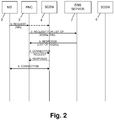
- Fig. 2 refers to a case, in which the radio access network controller such as RNC 3 used the proposed method to determine which SGSN to use for handling a connection to a user equipment MS 2.
- MS 2 sends a request, e.g. a RRC connection message, optionally including the CN identifier identifying the serving node in which the MS 2 may be registered.
- the RNC 3 detects the new RAI directely from the cell where the MS is located.. Then the RNC selects the SGN by using a list as depicted in figure 5 and the proposed method. This list may be preconfigured in RNC or retrieved from another network element like showed by step 2) and 3).
- the RNC sends a request to the DNS server 7 requesting a list of SGSNs available for the routing area.
- This request indicates the routing area identity RAI.
- the DNS server 7 checks the table memory containing the SGSN list such as shown in Fig. 5 , by selecting only those SGSNs corresponding to the indicated routing area.
- the DNS server 7 returns the list of selected SGSNs to the RNC 3.
- the RNC 3 may also send, in step 2.) additionally, or only, the CN identifier received from MS 2, to the DNS server 7.
- the DNS server 7 may, in this case, be adapted to use the CN identifier for selection of the appropriate SGSN from the list, and returns, in step 3.) merely the IP address of the appropriate SGSN.
- the RNC 3 will then establish, in steps 4.) to 6.), a connection using this single received IP address of the desired SGSN.
- the RNC 3 selects one SGSN according to the following proposed method: If the CN Id is or was sent in the signalling, the RNC uses the CNid as a key and the area to select the right serving node.
- the area does not need to be used in the special case where the area(s) handled by RNC have same configuration (e.g. RNC handles only one RA).
- the RNC may check the type of the serving node.
- an RNC when handling a packet connection, needs to select a serving node of SGSN type (and not MSC/VLR).
- the RNC needs to select an appropriate one, i.e. a 3G SGSN for an RNC.
- the RNC finds a suitable serving node, it will use the serving node address indicated in the list to establish the connection.
- the RNC could select any serving node of the suitable type supporting this area. This selection may be done randomly to spread the load, based on preferred serving node(s) (e.g. located close to RNC), or based on known information of the respective load of charging nodes (e.g. from operation and maintenance or DNS system) to select the less loaded serving node, or a combination of the above.
- preferred serving node(s) e.g. located close to RNC
- known information of the respective load of charging nodes e.g. from operation and maintenance or DNS system
- the RNC could select the serving node according to either of the following embodiments:
- the RNC could select any serving node of the suitable type supporting this area. This selection may be done randomly to spread the load, based on preferred serving node(s) (e.g. located close to RNC), or based on known information of the respective load of charging nodes (e.g. from operation and maintenance procedures, or DNS system) to select the less loaded serving node, or a combination of the above. If some of the information above is implicitly indicated by the order of the list (e.g. Serving nodes ranked from less loaded to more loaded) the RNC 3 may be adapted to select an SGSN indicated at a specific place of the list.
- the RNC has to select a default serving node for this area. This is needed to be sure that next time a connection is established from same mobile (still not indicated by its CN identifier), the same node is selected again.
- a new serving node may be selected when the area changes (similar to existing behaviour).
- the new serving node needs to find the old serving node. The new serving node will need to also use the default serving node handling the old area when no CN identifier is sent. This way the address of the old serving node can always be retrieved unambiguously.
- the RNC 3 subsequently performs, in the known manner, the necessary steps for establishing the connection between the MS 2 and the selected SGSN 4.
- the list of SGSNs sent in response 3. may contain additional information such as load information to be checked by RNC 3 for determining on the SGSN to be selected.
- connection to the selected SGSN may fail, in this case the RNC may retry with another Serving node of the appropriate type supporting this area.
- a new SGSN may be selected as the default, typically a secondary default.
- the new serving node will try first to connect to the default (as previously). If the default SGSN is down or not knowing the user, the new SGSN should retry using the secondary default serving node handling the old area when no CN identifier is sent. This way the address of the old serving node can always be retrieved unambiguously.
- a SGSN When a SGSN is scheduled for operation and maintenance procedures, it may be excluded from the list sent back in response to 3.) a certain or determined time interval such as several hours before the scheduled maintenance time point so as to avoid connections to be newly established to this SGSN.
- the DNS server 7 will be informed by the operation and maintenance system on the SGSN(s) scheduled for maintenance operations, and will either no longer select such an SGSN from the list, or will exclude same, when having retrieved the available SGSNs from the memory, from transmission to the RNC 3. Therefore, when the SGSN is shut down for operation and maintenance procedures, the number of registered users in this SGSN is minimum. These user connections may just be lost, or they may be sent to a new SGSN configured to use for this area the same CN identifier as the SGSN being shut down.
- Fig. 3 refers to a case where the MS 2 is intending to be connected to a certain SGSN 6, e.g. when re-establishing a connection.
- the MS 2 sends a request such as a RRC message which includes an SGSN identifier identifying the desired SGSN 6.
- a request such as a RRC message which includes an SGSN identifier identifying the desired SGSN 6.
- the routing area identity (RAI) or location area identity (LAI) can be additionally indicated.
- the RNC 3 can deduce the routing (or location) area, and thus the routing (or location) area identity, from other parameters. Similar to step 2.) of Fig. 2 , the RNC 3 requests, in a step 2.) of Fig. 3 , the DNS server 7 to send back a list of SGSNs by indicating location position such as RAI as a selection criterion.
- the DNS server 7 retrieves from the serving node list such as shown in Fig. 5 a sub-list of IP addresses and identifiers of SGSNs corresponding to, and being able to serve, the indicated location area.
- the DNS server 7 returns this sub-list to RNC 3 a response in step 3.).
- the RNC 3 selects that SGSN (here: SGSN 6) from the sub-list received in step 3.) which corresponds to the SGSN identifier indicated by MS 2 in step 1.), and performs the known connection steps 4.) to 6) for establishing the connection between MS 2 and the desired SGSN 6.
- SGSN here: SGSN 6
- the RNC 3 may also send, in step 2.) additionally, or only, the SGSN identifier received from MS 2, to the DNS server 7.
- the DNS server 7 may, in this case, be adapted to use the SGSN identifier for selection of the appropriate SGSN from the list, and returns, in step 3.) merely the IP address of the appropriate SGSN.
- the RNC 3 will then establish, in steps 4.) to 6.), a connection using this single received IP address of the desired SGSN.
- Fig. 4 shows an additional function not forming part of the invention the invention.
- one of the SGSNs here the SGSN 4
- the step 1.) of Fig. 4 consists in sending a message such as a RRC connection request, from MS 2 to RNC 3, indicating the routing area identifier RAI.
- the RNC 3 recognises from the lack of any SGSN identifier requesting a connection to a specific SGSN, the possibility of selecting the default SGSN for the indicated routing area.
- the RNC 3 then inquires, in step 2.) a database 8 for returning the address of the default SGSN 4, and indicates the routing area identity in the inquiring message.
- the database 8 may be structured similar to the table shown in Fig. 5 and may be contained in, or accessible by, a DNS server 7, or another server.
- the database 8 returns, in response 3.), the address of the default SGSN which address is used by RNC 3 in the customary manner for establishing a connection between MS 2 and the default SGSN 4, as represented by steps 4.) to 6.).
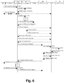
- Fig. 6 shows the steps of a Routeing Area Update Procedure in an implementation not forming part of the invention, related to UMTS. Some of the modifications of this embodiment, as compared to the specifications, are emphasized by using bold letters.
- a routeing area update takes place when an attached MS detects that it has entered a new RA or when the periodic RA update timer has expired.
- the SGSN detects that it is an intra SGSN routeing area update by noticing that it also handles the old RA. In this case, the SGSN has the necessary information about the MS and there is no need to inform the GGSNs or the HLR about the new MS location.
- a periodic RA update is always an intra SGSN routeing area update. If the network operates in mode I, then an MS that is both GPRS-attached and IMSI-attached shall perform the Combined RA / LA Update procedures.
- an RA update is either intra-SGSN or inter-SGSN RA update, either combined RA / LA update or only RA update, either initiated by an MS in PMM-CONNECTED or in PMM-IDLE state. All the RA update cases are contained in the procedure illustrated in Fig. 6 .
- CN identifier (eventually associated with a CN type indicating CS) to message 1 (Routing area update request) and to message 13 (Routing area update accept).
- CN identifier should be added in Gs interface to message 10 (Location update request) and to message 12 (Location update accept). This supposes that the SGSN is capable of deriving MSC address from LAI and CN identifier, or at least from only LAI (as long as one SGSN always selects same MSC address for same LA, no unnecessary inter MSC/VLR location update is performed if SGSN do not change).
- Another example of a procedure where the method to select serving node based on CN identifier may be used, is a Combined Cell / URA Update and SRNS Relocation Procedure.
- the Combined Cell / URA Update and SRNS Relocation procedure is used to move the UTRAN to CN connection point at the UTRAN side from the source SRNC to the target RNC, while performing a cell re-selection in the UTRAN.
- the Iu links are relocated.
- an Intra SGSN SRNS Relocation procedure is performed. If the routeing area is changed, then this procedure is followed by an Intra SGSN Routeing Area Update procedure.
- the SGSN detects that it is an intra-SGSN routeing area update by noticing that it also handles the old RA. In this case, the SGSN has the necessary information about the MS and there is no need to inform the HLR about the new MS location.
- the MS Before the Combined Cell / URA Update and SRNS Relocation and the Routeing Area Update the MS is registered in the old SGSN.
- the source RNC is acting as serving RNC.
- the MS After the Combined Cell / URA Update and SRNS Relocation and the Routeing Area Update, the MS is registered in the new SGSN The MS is in state PMM-CONNECTED towards the new SGSN, and the target RNC is acting as serving RNC.
- Fig. 7 The Combined Cell / URA Update and SRNS Relocation procedure for the PS domain is illustrated in Fig. 7 .
- the sequence is valid for both intra-SGSN SRNS relocation and inter-SGSN SRNS relocation. The steps will be described by referring to the numbering shown in Fig. 7 .
- the MS indicates the same CN identifier as used by old SGSN to find the new SGSN , so that the SGSN that is selected by the new SRNC, is the same as the one that has already been selected by the old SGSN.
- An alternative solution would be that the old SGSN selects anyone of the SGSN capable to connect to the target RNC based on target ID. Then the new SGSN sends its CN identifier to the MS, e.g. by adding CN identifier in message 4 (Relocation Request) and 10 (Cell Update Confirm / URA Update Confirm message). Then the MS uses the CN id for the update selecting the right SGSN.
- the coding of the CN identifier is optimised to allow enough serving nodes to handle the same area, but not to increase too much radio signaling.
- the coding is therefore to use 4 bits, providing 16 serving nodes but not much overhead.
- a given code (e.g. 0000) should indicate the default serving node for all areas.
- another code (e.g. 0001) should indicate the secondary default serving node.
- This implementation would reduce need to configure an additional parameter as default.
- a node e.g. RNC
- selects the default it can be implemented as using known default value of CN identifier (e.g. 0000) to query the list and retrieve (default) serving node address.
- Gs interface and a simultaneous PS/CS attachment if an association between the SGSN and the MSC is created (e. g. the UE (user equipment) performs a combined PS / CS attach), the SGSN is provided with, or has access to, a translation table to derive the MSC address from the RAI. Changes are needed to the translation table if multiple MSCs may control the same location area. An additional identifier, the MSC Identifier, may be provided to find a specific MSC controlling a location area.
- Fig. 8 illustrates a message flow in a system and method according to a further embodiment of the invention.
- This embodiment relates to a MVNO (Mobile Virtual Network Operator) having at least one own core network (CN) element 6, 10, 11 such as an MSC/VLR (Mobile Switching Center/Visitor Location Register) and/or SGSN 6.
- CN core network
- MSC/VLR Mobile Switching Center/Visitor Location Register
- This embodiment may, but not exclusively, be targeted to GPRS, and future UMTS systems, especially in a case where multiple CN elements such as SGSN/MSC can be connected to the same RNC.
- the different CN elements can belong to different operators.
- the MS 2 may store the CN Ids (Identifiers) on the SIM inserted or insertable in the MS 2.
- Figs. 8 and 9 include the feature of using an operator ID to select a CN node belonging to the right MVNO operator when connecting to the network.
- Two methods are presented: (1) operator Id is broadcast to the MS 2 and MS 2 makes the decision; (2) operator Id is sent from MS 2 to RNC 3 and RNC 3 selects the CN Id.
- the embodiment according to Fig. 8 is directed to the first method whereas Fig. 9 embodiment implements the second method. With both methods, one MVNO operator may have more than one node such as SGSN covering the same area.
- the first method shown in Fig. 8 includes step 1. of broadcasting information to the MS 2 indicating the mapping between a certain MVNO operator and the CN ID used in this area.
- the MS 2 then performs a selection step 2 for selecting it favourite operator (i.e. MVNO) in accordance with stored internal selection criteria.
- the corresponding CN Id (as received in step 1. or as stored inside MS 2) of the selected operator is inserted as part of the RRC connect request message 3. sent to RNC 3.
- the RNC 3 will then establish the connection with the corresponding CN element 6, 10, or 11 identified by the transmitted CN Id, as shown by steps 4. to 6.
- the CN Id of the MSC/VLR and SGSN of the same operator may be the same to limit the amount of information broadcast.
- SGSN and/or MSC/VLR for this MVNO may be indicated in the broadcast message of step 1.
- CN Id only part of CN Id is broadcast in step 1. (e.g. 2 first bits) while the other necessary bits, e.g. the last two bits are selected arbitrarily by MS 2. This allows MNVO to have multiple CN elements per RAN.
- the information broadcasted may for example be:
- the MS 2 If the MS 2 has no preference (or does not support the feature), it does not send CN Id in step 3 and may then be connected to a default CN element.
- global operators have a global operator ID.
- One practical way is to allocate the global operator IDs from the range of an unused country code, e.g.:
- An alternative implementation is to avoid broadcasting any parameter, but letting the MS 2 send in first RRC message (together or instead of CN Id) the operator identifier.
- This alternative is implemented in the embodiment according to Fig. 9 .
- the operator identifier may e.g. be mnc/mcc (easier as it is on SIM) but may also be a global operator ID (see above) or other type of identifier.
- Fig. 9 shows a message flow in a system and method according to this embodiment of the invention.
- This embodiment likewise relates to a MVNO (Mobile Virtual Network Operator) having at least one own core network element 6, 10, 11 such as an MSC/VLR (mobile switching center/visitor location register) and/or SGSN 6.
- MSC/VLR mobile switching center/visitor location register
- an MS 2 not having stored a CN Id adds its operator identifier in the Connection request message 1. when the MS 2 makes the first RRC connection.
- the RNC 3 has means (e.g. access to a configurable database) to check whether one of the available CN Ids corresponds to this operator identifier. This check or selection is represented by step 2. If one of the available CN Ids corresponds to the operator identifier sent from MS 2, this CN Id is selected and the connection is established to the CN node 6, 10, or 11 corresponding to the selected CN Id.
- the CN node will indicate in MM signaling the selected CN identifier (CN Id) to the MS 2.
- the connection is established in a known manner according to steps 3. to 5. of Fig. 9 .
- the MVNO uses the same CN identifier across the complete host PLMN (i.e. MVNO use same CN identifier across the different LAs (or RAs)). This means that when the MS moves from one CN area to another, the same CN identifier corresponds to a node of same MVNO in the new CN area.
- a CN area is the full area reachable from one CN node, and is composed of one or many Location Area LA (or Routing Area RA). In a small network it may cover the whole country. Also a small MVNO may have one CN node for the full country, while another MVNO may have many CN nodes.
- the MS will in subsequent RRC connection establishment messages send only CN Id and not operator identifier, as long as it is in same PLMN.
- CN Id may be used based on the configuration and is useful in the case where a MVNO has an agreement with a transnational operator (the same CN node may cover more than one country/PLMN).
- the MVNO may use different CN identifier across the different LAs (or RAs) (but inside one LA (or RA) CN identifier is unique). This means that when the MS moves from one LA (or RA) to another, a different CN may be used by the same MVNO in the new LA (or RA).
- the MS will in subsequent RRC connection establishment messages send only CN Id and not operator identifier, as long as it is in same LA (or RA).
- CN Id may be used based on configuration and is useful in a case where a MVNO has an agreement with a transnational operator (the same CN node may cover more than one country/PLMN, and/or the MVNO may have two or more CN nodes per area).
- the following implementation may be used:
- the invention according to the embodiments of Figs. 8 , 9 overcomes the problem of modifying the SIM card. Many operators prefer to keep the same SIM card to avoid the cost of changing old SIM card.
- broadcasting information over the radio or sending operator ID (e.g. read on SIM) from MS 2 is more flexible.
- Different CN Ids may be used in different regions. For example if Orange is MVNO all over Europe, the SIM does not need to know which CN Id is used in which country.
- the invention according to Figs. 8 , 9 covers the field of MNVO. It takes advantage of the feature of multiple CNs per radio network and provides a solution therefor.
- the invention is not limited thereto and may also be implemented in networks of different types using serving nodes of different structure such as MSC/VLR.
Claims (8)
- Appareil d'équipement utilisateur, configuré pour :stocker un identificateur d'élément de réseau coeur ;ajouter ledit identificateur d'élément de réseau coeur à un message RRC pour établir une connexion RRC ; etenvoyer ledit message RRC comprenant ledit identificateur d'élément de réseau coeur sur une connexion radio à un élément de réseau d'un réseau d'accès radio pour établir une connexion à l'un d'un ensemble d'éléments de réseau coeur auquel ledit appareil se connectera.
- Appareil selon la revendication 1, dans lequel ladite connexion RRC est établie entre ledit appareil et ledit élément de réseau dudit réseau d'accès radio.
- Appareil selon l'une quelconque des revendications 1 et 2, dans lequel ledit identificateur d'élément de réseau coeur est un dernier identificateur d'élément de réseau coeur reçu d'un réseau.
- Appareil selon l'une quelconque des revendications 1 à 3, dans lequel ledit appareil est une station mobile, et/ou ledit élément de réseau dudit réseau d'accès radio est au moins l'un d'un contrôleur de réseau radio, RNC, et d'un contrôleur de station de base, BSC.
- Procédé pour un équipement utilisateur, le procédé comprenant :le stockage d'un identificateur d'élément de réseau coeur ;l'ajout dudit identificateur d'élément de réseau coeur à un message RRC pour établir une connexion RRC ; etl'envoi dudit message RRC comprenant l'identificateur d'élément de réseau coeur sur une connexion radio à un élément de réseau d'un réseau d'accès radio pour établir une connexion à l'un d'un ensemble d'éléments de réseau coeur auquel ledit appareil se connectera.
- Procédé selon la revendication 5, dans lequel ladite connexion RRC est établie entre ledit équipement utilisateur et ledit élément de réseau dudit réseau d'accès radio.
- Procédé selon l'une quelconque des revendications 5 et 6, dans lequel ledit identificateur d'élément de réseau coeur est un dernier identificateur d'élément de réseau coeur reçu d'un réseau.
- Procédé selon l'une quelconque des revendications 5 à 7, dans lequel ledit équipement utilisateur est une station mobile, et/ou ledit élément de réseau dudit réseau d'accès radio est au moins l'un d'un contrôleur de réseau radio, RNC, et d'un contrôleur de station de base, BSC.
Priority Applications (1)
| Application Number | Priority Date | Filing Date | Title |
|---|---|---|---|
| EP18190214.9A EP3425973B1 (fr) | 2000-05-22 | 2001-01-19 | Appareil et procédé de fourniture de connexion |
Applications Claiming Priority (4)
| Application Number | Priority Date | Filing Date | Title |
|---|---|---|---|
| PCT/EP2000/004647 WO2001091382A1 (fr) | 2000-05-22 | 2000-05-22 | Systeme et procede permettant d'obtenir une connexion dans un reseau de communication |
| PCT/EP2001/000615 WO2001091370A2 (fr) | 2000-05-22 | 2001-01-19 | Systeme et procede permettant d'etablir une connexion dans un reseau de communication |
| EP01901180A EP1287642B1 (fr) | 2000-05-22 | 2001-01-19 | Système et procédé permettant d'établir une connexion dans un réseau de communication |
| EP08163793.6A EP2007088B1 (fr) | 2000-05-22 | 2001-01-19 | Élément de réseau, procédé et système de fourniture de connexion |
Related Parent Applications (2)
| Application Number | Title | Priority Date | Filing Date |
|---|---|---|---|
| EP01901180A Division EP1287642B1 (fr) | 2000-05-22 | 2001-01-19 | Système et procédé permettant d'établir une connexion dans un réseau de communication |
| EP08163793.6A Division EP2007088B1 (fr) | 2000-05-22 | 2001-01-19 | Élément de réseau, procédé et système de fourniture de connexion |
Related Child Applications (2)
| Application Number | Title | Priority Date | Filing Date |
|---|---|---|---|
| EP18190214.9A Division-Into EP3425973B1 (fr) | 2000-05-22 | 2001-01-19 | Appareil et procédé de fourniture de connexion |
| EP18190214.9A Division EP3425973B1 (fr) | 2000-05-22 | 2001-01-19 | Appareil et procédé de fourniture de connexion |
Publications (3)
| Publication Number | Publication Date |
|---|---|
| EP2934050A1 EP2934050A1 (fr) | 2015-10-21 |
| EP2934050B1 true EP2934050B1 (fr) | 2018-10-03 |
| EP2934050B8 EP2934050B8 (fr) | 2018-11-07 |
Family
ID=8163955
Family Applications (4)
| Application Number | Title | Priority Date | Filing Date |
|---|---|---|---|
| EP08163793.6A Expired - Lifetime EP2007088B1 (fr) | 2000-05-22 | 2001-01-19 | Élément de réseau, procédé et système de fourniture de connexion |
| EP18190214.9A Expired - Lifetime EP3425973B1 (fr) | 2000-05-22 | 2001-01-19 | Appareil et procédé de fourniture de connexion |
| EP15170199.2A Revoked EP2934050B8 (fr) | 2000-05-22 | 2001-01-19 | Dispositif et procédé de fourniture de connexion |
| EP01901180A Expired - Lifetime EP1287642B1 (fr) | 2000-05-22 | 2001-01-19 | Système et procédé permettant d'établir une connexion dans un réseau de communication |
Family Applications Before (2)
| Application Number | Title | Priority Date | Filing Date |
|---|---|---|---|
| EP08163793.6A Expired - Lifetime EP2007088B1 (fr) | 2000-05-22 | 2001-01-19 | Élément de réseau, procédé et système de fourniture de connexion |
| EP18190214.9A Expired - Lifetime EP3425973B1 (fr) | 2000-05-22 | 2001-01-19 | Appareil et procédé de fourniture de connexion |
Family Applications After (1)
| Application Number | Title | Priority Date | Filing Date |
|---|---|---|---|
| EP01901180A Expired - Lifetime EP1287642B1 (fr) | 2000-05-22 | 2001-01-19 | Système et procédé permettant d'établir une connexion dans un réseau de communication |
Country Status (12)
| Country | Link |
|---|---|
| US (1) | US7782818B2 (fr) |
| EP (4) | EP2007088B1 (fr) |
| JP (2) | JP3828424B2 (fr) |
| KR (2) | KR100917744B1 (fr) |
| CN (2) | CN100426779C (fr) |
| AT (1) | ATE422751T1 (fr) |
| AU (2) | AU2000245676A1 (fr) |
| BR (1) | BRPI0111035B1 (fr) |
| CA (2) | CA2774301A1 (fr) |
| DE (1) | DE60137627D1 (fr) |
| ES (1) | ES2539764T3 (fr) |
| WO (2) | WO2001091382A1 (fr) |
Families Citing this family (166)
| Publication number | Priority date | Publication date | Assignee | Title |
|---|---|---|---|---|
| US6360100B1 (en) * | 1998-09-22 | 2002-03-19 | Qualcomm Incorporated | Method for robust handoff in wireless communication system |
| WO2001091382A1 (fr) | 2000-05-22 | 2001-11-29 | Nokia Corporation | Systeme et procede permettant d'obtenir une connexion dans un reseau de communication |
| DE10027872B4 (de) * | 2000-06-06 | 2005-10-13 | Siemens Ag | Mobilfunk-Kommunikationssystem und Betriebsverfahren dafür |
| US7734683B1 (en) * | 2000-07-11 | 2010-06-08 | Nokia Corporation | Method for providing a DNS server address list from a server to a client |
| US7302251B2 (en) * | 2000-10-06 | 2007-11-27 | Nortel Networks Limited | Channel request and contention resolution apparatus and method |
| US6564059B1 (en) | 2000-10-11 | 2003-05-13 | Lucent Technologies Inc. | Modification of link identifier to include routing label that allows base station message routing to serving processor |
| US7058068B2 (en) * | 2000-11-30 | 2006-06-06 | Nortel Networks Limited | Session initiation protocol based advanced intelligent network/intelligent network messaging |
| US6708031B2 (en) * | 2000-12-05 | 2004-03-16 | Nokia Corporation | Session or handoff methods in wireless networks |
| KR100470687B1 (ko) * | 2000-12-28 | 2005-03-08 | 엘지전자 주식회사 | 인터넷 프로토콜 기반의 핵심 망에서 무선 이동 통신액세스 망을 연동하기 위한 방법 및 시스템 |
| DE10117269B4 (de) * | 2001-03-30 | 2005-12-08 | Siemens Ag | Verfahren zur Zuordnung eines mobilen Kommunikationsendgerätes zu einem Corenetzwerkknoten |
| NO20014065D0 (no) * | 2001-08-21 | 2001-08-21 | Ericsson Telefon Ab L M | Handtering av flytkontrollmekanismer i pakkesvitsjede mobilkommunikasjonsnett |
| NO20014064D0 (no) * | 2001-08-21 | 2001-08-21 | Ericsson Telefon Ab L M | Fremgangsmate for handtering av en mobil abonnent i et telekommunikasjonssystem |
| EP1442573B1 (fr) | 2001-10-08 | 2010-05-19 | Nokia Corporation | Service et negociation de capacites de fonctionnement dans un reseau utilisant un seul mode de numerotage |
| WO2003045095A1 (fr) * | 2001-11-21 | 2003-05-30 | Nokia Corporation | Radiodiffusion a des equipements utilisateurs mobiles de donnees concernant des exploitants de reseau habilites |
| CN1172469C (zh) * | 2001-12-13 | 2004-10-20 | 华为技术有限公司 | 一种自主选择加密算法实现保密通信的方法 |
| ATE323356T1 (de) * | 2002-01-08 | 2006-04-15 | Netzwerkauswahl für eine verbindung | |
| US20030139183A1 (en) * | 2002-01-11 | 2003-07-24 | Nokia Corporation | Method and apparatus for reducing premature termination of mobile station LCS procedure during RR operations |
| NO20020290D0 (no) * | 2002-01-18 | 2002-01-18 | Ericsson Telefon Ab L M | Fremgangsmåte ved roaming i mobilnett |
| ATE464766T1 (de) * | 2002-02-09 | 2010-04-15 | Ericsson Telefon Ab L M | Zuordnungsaktualisierung von einem dienstunterstützungsknoten zu einer sammlung von mobilfunkvermittlungsstellen |
| JP3738737B2 (ja) | 2002-03-04 | 2006-01-25 | 日本電気株式会社 | 通信システムおよび移動端末間通信方法 |
| WO2003092189A1 (fr) * | 2002-04-25 | 2003-11-06 | Nec Corporation | Systeme de reseau de communication mobile et procede de communication mobile |
| EP1523821B1 (fr) | 2002-06-21 | 2011-08-24 | Thomson Licensing | Enregistrement d'un reseau local sans fil comme zone de routage du systeme universel de telecommunication avec les mobiles (umts) en vue d'un interfonctionnement reseau local-umts |
| WO2004016010A1 (fr) * | 2002-08-13 | 2004-02-19 | Thomson Licensing S.A. | Protection de l'identite des utilisateurs dans un agencement d'interconnexion de systemes universels de telephonie mobile par reseau local sans fil |
| KR100443198B1 (ko) * | 2002-08-30 | 2004-08-09 | (주)아이피캐스트 | Ip 네트워크를 이용한 음성 방송 시스템 구성 방법 및장치 |
| KR100392767B1 (ko) | 2002-09-05 | 2003-07-28 | 에스케이 텔레콤주식회사 | 가입자 기반 링백톤 서비스에서의 음원제공장치로의라우팅 제어 방법 |
| JP4133274B2 (ja) | 2002-12-04 | 2008-08-13 | 株式会社エヌ・ティ・ティ・ドコモ | コンテンツ配信システム、中継装置及びコンテンツ配信制御方法 |
| US7668541B2 (en) | 2003-01-31 | 2010-02-23 | Qualcomm Incorporated | Enhanced techniques for using core based nodes for state transfer |
| US6862446B2 (en) * | 2003-01-31 | 2005-03-01 | Flarion Technologies, Inc. | Methods and apparatus for the utilization of core based nodes for state transfer |
| US7415274B2 (en) | 2003-02-19 | 2008-08-19 | Nokia Corporation | Routing procedure for a communication system |
| FR2851867B1 (fr) * | 2003-02-28 | 2005-06-24 | Cit Alcatel | Ordonnancement d'adresses dans serveur de noms de domaine |
| US8473635B1 (en) * | 2003-05-19 | 2013-06-25 | Akamai Technologies, Inc. | Provisioning tool for a distributed computer network |
| US7400593B2 (en) * | 2003-08-15 | 2008-07-15 | Samsung Electronics Co., Ltd | Method for distinguishing MBMS service request from other service requests |
| DE60301071T2 (de) * | 2003-09-19 | 2005-12-29 | Telefonaktiebolaget Lm Ericsson (Publ) | Verfahren, Steuergerät und Netzwerkknoten zur Aufrechterhaltung einer Verbindung im Falle einer anstehenden Anfrage |
| US20050090251A1 (en) | 2003-10-07 | 2005-04-28 | Ravi Kuchibhotla | Apparatus and method for shared network |
| US7561879B2 (en) * | 2003-10-07 | 2009-07-14 | Motorola, Inc. | Wireless access network sharing among core networks and methods |
| US7305251B2 (en) * | 2003-10-07 | 2007-12-04 | Motorola Inc. | Method for selecting a core network |
| US7586901B2 (en) * | 2003-10-17 | 2009-09-08 | International Business Machines Corporation | Data instance routing with configurable user profile |
| GB0326944D0 (en) * | 2003-11-19 | 2003-12-24 | Nokia Corp | A method for service management in communications system |
| US7551583B1 (en) * | 2003-12-16 | 2009-06-23 | At&T Mobility Ii Llc | Method and system for coordinating operation modes of a GPRS network |
| CN100337444C (zh) * | 2003-12-24 | 2007-09-12 | 华为技术有限公司 | 一种无线局域网中重定向分组数据关口的方法 |
| CN100441026C (zh) * | 2003-12-26 | 2008-12-03 | 华为技术有限公司 | 一种在共享网络中进行网络选择的方法 |
| CN100387022C (zh) * | 2004-03-18 | 2008-05-07 | 华为技术有限公司 | 一种使用不同版本的ip协议的gsn之间的通讯方法 |
| JP4301989B2 (ja) * | 2004-03-31 | 2009-07-22 | 株式会社エヌ・ティ・ティ・ドコモ | 移動通信方法及び無線制御装置 |
| JP4288199B2 (ja) * | 2004-03-31 | 2009-07-01 | 株式会社エヌ・ティ・ティ・ドコモ | 移動通信方法、移動局及び無線制御装置 |
| US20070232338A1 (en) * | 2004-05-13 | 2007-10-04 | Hakan Niska | System for Allocating Mobile Stations to a Core Network in an Unlicensed Radio Access Network |
| CN100391274C (zh) * | 2004-06-08 | 2008-05-28 | 华为技术有限公司 | 通用分组无线业务服务支持节点路由区更新方法 |
| EP1785002B1 (fr) * | 2004-08-28 | 2008-10-29 | Telefonaktiebolaget LM Ericsson (publ) | Agencement et procede dans des reseaux de communication |
| CN100344171C (zh) * | 2004-09-23 | 2007-10-17 | 华为技术有限公司 | 无线网络系统及应用无线网络系统实现数据传输的方法 |
| GB0422192D0 (en) * | 2004-10-06 | 2004-11-03 | Nokia Corp | Transfer of a user equipment in a communication system |
| EP1646189A1 (fr) * | 2004-10-06 | 2006-04-12 | Matsushita Electric Industrial Co., Ltd. | Transfert d'un réseau de radiocommunication WLAN vers un réseau de radiocommunication UMTS avec activation demandée par le réseau d'un contexte de protocol de données par paquets |
| US8843995B2 (en) | 2004-11-02 | 2014-09-23 | Blackberry Limited | Generic access network (GAN) controller selection in PLMN environment |
| KR101119096B1 (ko) * | 2004-11-04 | 2012-09-05 | 엘지전자 주식회사 | 광대역 무선접속 시스템에서 핸드오버시 적용되는 데이터전송 방법 |
| US7437470B2 (en) * | 2004-11-18 | 2008-10-14 | International Business Machines Corporation | Tunneling IPv6 packets |
| KR20070091176A (ko) | 2004-11-29 | 2007-09-07 | 리서치 인 모션 리미티드 | 무선 사용자 설비(ue) 장치에 운영자-차등 메시징을제공하는 시스템 및 방법 |
| AU2005242125B2 (en) * | 2004-12-07 | 2007-10-04 | Samsung Electronics Co., Ltd. | Method and apparatus for informing a radio access network of a selected core network from user equipment in a network sharing system |
| SE529376C3 (sv) * | 2004-12-30 | 2007-08-21 | Teliasonera Ab | Metod och system för styrning av tjänsteaccess i samutnyttjade nät |
| KR101215028B1 (ko) * | 2004-12-30 | 2012-12-24 | 텔레포 스웨덴 아베 | 대체 경로 설정을 위해 적응된 셀룰러 원격통신 네트워크에서의 방법 및 서버 |
| DE102005005254B4 (de) * | 2005-02-04 | 2007-05-10 | Infineon Technologies Ag | Mobilfunk-Kommunikationssystem, Verfahren zum Betreiben eines Mobilfunk-Kommunikationssystems, Kernnetz-Vermittlungsschicht-Einheit und Verfahren zum Betreiben einer Kernnetz-Vermittlungsschicht-Einheit |
| US9967785B2 (en) * | 2005-03-23 | 2018-05-08 | Telefonaktiebolaget Lm Ericsson (Publ) | Apparatus and methods for improved handover in multi-operator shared radio access network communications systems |
| CN101142837B (zh) * | 2005-03-24 | 2011-04-06 | 松下电器产业株式会社 | 通信管理装置、通信控制装置和无线通信系统 |
| US20060234709A1 (en) * | 2005-03-30 | 2006-10-19 | Nokia Corporation | System, devices, methods and programs for reducing service interruption during routing area change |
| ATE541430T1 (de) * | 2005-03-31 | 2012-01-15 | Ericsson Telefon Ab L M | Technik zum koordinieren von cs- und ps- registrationen in einem mehrbetreiber- kernnetzwerk |
| FI20050369A0 (fi) * | 2005-04-12 | 2005-04-12 | Nokia Corp | Verkkoelementin valinta |
| US7664495B1 (en) * | 2005-04-21 | 2010-02-16 | At&T Mobility Ii Llc | Voice call redirection for enterprise hosted dual mode service |
| EP1718094A1 (fr) * | 2005-04-28 | 2006-11-02 | Research In Motion Limited | Système et procèdè de publicité sur réseau utilisant une système publicitaire Courtier |
| US8060084B2 (en) | 2005-04-28 | 2011-11-15 | Research In Motion Limited | Network selection scheme using a roaming broker (RB) |
| US20060246899A1 (en) | 2005-04-28 | 2006-11-02 | Research In Motion Limited | System and method for providing network advertisement information via a network advertisement broker (NAB) |
| US7817622B2 (en) * | 2005-05-19 | 2010-10-19 | Nokia Corporation | Unlicensed mobile access optimization |
| CN100396114C (zh) * | 2005-06-09 | 2008-06-18 | 华为技术有限公司 | 在联合路由/位置更新中实现负载重分配的方法 |
| WO2006133622A1 (fr) * | 2005-06-13 | 2006-12-21 | Huawei Technologies Co., Ltd. | Système de commande de passerelle de paquets/périphérie et procédé de commande par la passerelle de paquets/périphérie |
| FR2888078B1 (fr) * | 2005-06-30 | 2007-08-10 | Alcatel Sa | Procede de transfert d'une communication impliquant un noeud mobile en situation de macro-mobilite au sein d'un reseau de communication ip a routage hierarchique |
| EP2007155B1 (fr) * | 2005-07-01 | 2012-01-11 | Research In Motion Limited | Système et procédé pour gérer des listes de réseaux interdits dans un dispositif d'équipement de l'utilisateur (UE) sans fil |
| US8428584B2 (en) | 2005-07-01 | 2013-04-23 | Research In Motion Limited | System and method for accelerating network selection by a wireless user equipment (UE) device |
| US7826842B2 (en) * | 2005-07-01 | 2010-11-02 | Research In Motion Limited | System and method for managing forbidden network lists on a wireless user equipment (UE) device |
| CN100461753C (zh) * | 2005-07-15 | 2009-02-11 | 华为技术有限公司 | 虚交换体系中的路径选择方法 |
| CN100414931C (zh) * | 2005-07-15 | 2008-08-27 | 华为技术有限公司 | 虚交换系统中业务转发的实现方法及系统 |
| KR101238993B1 (ko) * | 2005-08-25 | 2013-03-04 | 엘지전자 주식회사 | 이동통신 시스템에서의 트래픽 전송경로 재설정 방법 |
| US9066344B2 (en) * | 2005-09-19 | 2015-06-23 | Qualcomm Incorporated | State synchronization of access routers |
| US8983468B2 (en) | 2005-12-22 | 2015-03-17 | Qualcomm Incorporated | Communications methods and apparatus using physical attachment point identifiers |
| US9736752B2 (en) * | 2005-12-22 | 2017-08-15 | Qualcomm Incorporated | Communications methods and apparatus using physical attachment point identifiers which support dual communications links |
| US8982835B2 (en) * | 2005-09-19 | 2015-03-17 | Qualcomm Incorporated | Provision of a move indication to a resource requester |
| US20070083669A1 (en) * | 2005-09-19 | 2007-04-12 | George Tsirtsis | State synchronization of access routers |
| US8509799B2 (en) * | 2005-09-19 | 2013-08-13 | Qualcomm Incorporated | Provision of QoS treatment based upon multiple requests |
| US8982778B2 (en) * | 2005-09-19 | 2015-03-17 | Qualcomm Incorporated | Packet routing in a wireless communications environment |
| US9078084B2 (en) * | 2005-12-22 | 2015-07-07 | Qualcomm Incorporated | Method and apparatus for end node assisted neighbor discovery |
| US20070064948A1 (en) * | 2005-09-19 | 2007-03-22 | George Tsirtsis | Methods and apparatus for the utilization of mobile nodes for state transfer |
| ES2331141T3 (es) * | 2005-09-27 | 2009-12-22 | Telefonaktiebolaget Lm Ericsson (Publ) | Una arquitectura de red y un metodo relacionado con el acceso de estaciones de usuario. |
| US9301228B2 (en) * | 2005-09-29 | 2016-03-29 | Vringo, Inc. | Method, device, system and software product for providing system information to enable packet switched handover |
| RU2384020C2 (ru) * | 2005-09-30 | 2010-03-10 | Телефонактиеболагет Лм Эрикссон (Пабл) | Средства и способы для улучшения характеристик хэндовера интегрированных сетей радиодоступа |
| GB2431822A (en) * | 2005-10-27 | 2007-05-02 | Agilent Technologies Inc | Determing an IP address of a node |
| CN100421522C (zh) * | 2005-11-02 | 2008-09-24 | 上海华为技术有限公司 | 连接模式下实现网络共享的方法 |
| WO2007079771A1 (fr) * | 2006-01-09 | 2007-07-19 | Telefonaktiebolaget L M Ericsson (Publ) | Noeud et procede se rapportant a un transfert dans une communication mobile |
| US8199731B2 (en) * | 2006-01-25 | 2012-06-12 | Motorola Mobility, Inc. | Method and apparatus for facilitating switched packet data services on multiple networks |
| GB0601952D0 (en) * | 2006-01-31 | 2006-03-15 | M M I Res Ltd | Methods of maintaining connection with, and determining the direction of, a mobile device |
| GB2435364B (en) * | 2006-02-16 | 2008-05-21 | Motorola Inc | Handover between radio networks |
| US9083355B2 (en) | 2006-02-24 | 2015-07-14 | Qualcomm Incorporated | Method and apparatus for end node assisted neighbor discovery |
| GB0607084D0 (en) * | 2006-04-07 | 2006-05-17 | Nokia Corp | Managing connections in a mobile telecommunications network |
| EP1858278B1 (fr) | 2006-05-19 | 2013-05-15 | Research In Motion Limited | Système et procédé pour faciliter la sélection de réseau accélérée dans un environnement de réseau radio |
| US8010105B2 (en) | 2006-05-19 | 2011-08-30 | Research In Motion Limited | System and method for facilitating accelerated network selection using a weighted network list |
| JP4992308B2 (ja) | 2006-06-14 | 2012-08-08 | 日本電気株式会社 | 通信システム、動作制御方法、位置管理サーバ及びプログラム |
| FR2902952B1 (fr) * | 2006-06-21 | 2008-11-14 | Alcatel Sa | Systeme de communication pour la gestion centralisee, par un operateur virtuel, d'appels de terminaux d'abonnes connectes a des reseaux de communication d'accueil |
| US8391894B2 (en) * | 2006-06-26 | 2013-03-05 | Intel Corporation | Methods and apparatus for location based services in wireless networks |
| US8467792B2 (en) | 2006-06-27 | 2013-06-18 | Qualcomm Incorporated | Method and apparatus for maintaining call continuity in wireless communication |
| CN101111059B (zh) * | 2006-07-20 | 2010-05-12 | 华为技术有限公司 | 一种位置区和路由区联合更新的方法 |
| EP2052563B1 (fr) * | 2006-08-16 | 2013-10-16 | Telefonaktiebolaget LM Ericsson (publ) | Proxy ggsn pour une solution tunnel |
| CN104244219B (zh) * | 2006-08-16 | 2018-04-20 | 艾利森电话股份有限公司 | 用于一隧道解决方案的ggsn代理 |
| JP4848890B2 (ja) | 2006-08-23 | 2011-12-28 | 日本電気株式会社 | 移動通信システム及びその方法並びにそれに用いる基地局 |
| US7885654B2 (en) * | 2006-10-10 | 2011-02-08 | Apple Inc. | Dynamic carrier selection |
| US20080102831A1 (en) * | 2006-10-18 | 2008-05-01 | Ivan Ore | Method, system, network and device enabling deactivating a signalling free mode |
| JP5284577B2 (ja) | 2006-11-13 | 2013-09-11 | 日本電気株式会社 | 無線基地制御局およびルーチング方法 |
| EP2086246B1 (fr) * | 2006-11-16 | 2014-11-05 | NTT DoCoMo, Inc. | Dispositif et procédé de commande de communication |
| CN101203024B (zh) * | 2006-12-15 | 2012-05-23 | 华为技术有限公司 | 无线网络搜索方法和系统及多模设备 |
| US7970891B1 (en) * | 2007-01-17 | 2011-06-28 | Google Inc. | Tracking links in web browsers |
| KR101451431B1 (ko) * | 2007-03-15 | 2014-10-15 | 엘지전자 주식회사 | 핸드오버 동안 데이터 블록 관리 방법 |
| JP2008236183A (ja) * | 2007-03-19 | 2008-10-02 | Nec Corp | 呼セッション制御サーバ割り当て方法および呼セッション制御サーバ割り当てシステム |
| US20080235185A1 (en) * | 2007-03-21 | 2008-09-25 | Motorola, Inc. | Communication system and method of accessing therefor |
| US9155008B2 (en) * | 2007-03-26 | 2015-10-06 | Qualcomm Incorporated | Apparatus and method of performing a handoff in a communication network |
| US8830818B2 (en) * | 2007-06-07 | 2014-09-09 | Qualcomm Incorporated | Forward handover under radio link failure |
| JP5197999B2 (ja) * | 2007-06-18 | 2013-05-15 | 株式会社エヌ・ティ・ティ・ドコモ | アクセス網切り替え方法、アクセス網切り替え装置及び移動機 |
| US9094173B2 (en) | 2007-06-25 | 2015-07-28 | Qualcomm Incorporated | Recovery from handoff error due to false detection of handoff completion signal at access terminal |
| CN101374321B (zh) | 2007-08-22 | 2012-04-04 | 华为技术有限公司 | 一种演进网络切换处理方法与系统 |
| US8744478B2 (en) * | 2008-02-20 | 2014-06-03 | Qualcomm Incorporated | Method and apparatus for executing location dependent application in a mobile handset |
| US8515436B2 (en) | 2008-03-27 | 2013-08-20 | Qualcomm Incorporated | Management of wireless connections |
| CN101677470B (zh) * | 2008-09-18 | 2011-12-21 | 华为技术有限公司 | 服务请求的处理方法、装置及系统 |
| JP4950983B2 (ja) * | 2008-12-22 | 2012-06-13 | 株式会社エヌ・ティ・ティ・ドコモ | 移動通信方法及び無線制御装置 |
| US7917137B2 (en) * | 2009-02-04 | 2011-03-29 | Nokia Corporation | Optimization of uplink resource grant procedure and apparatus |
| CN102396275B (zh) * | 2009-02-17 | 2015-04-15 | 瑞典爱立信有限公司 | 用于控制通信网络的方法、服务器、包括服务器的系统 |
| EP2425584B1 (fr) | 2009-04-30 | 2013-02-13 | Telefonaktiebolaget LM Ericsson (publ) | Sélection d'un noeud de coeur de réseau dans un réseau de communication mobile |
| JP5257273B2 (ja) | 2009-06-30 | 2013-08-07 | 富士通株式会社 | 移動端末の認証方法およびその方法に用いられる装置 |
| CN102026093A (zh) * | 2009-09-17 | 2011-04-20 | 普天信息技术研究院有限公司 | 传输多媒体广播组播业务数据的方法及系统 |
| CN101742465A (zh) * | 2009-12-10 | 2010-06-16 | 华为技术有限公司 | 接入信息获取、发送方法、装置和系统 |
| US8615241B2 (en) | 2010-04-09 | 2013-12-24 | Qualcomm Incorporated | Methods and apparatus for facilitating robust forward handover in long term evolution (LTE) communication systems |
| JP5285678B2 (ja) * | 2010-06-18 | 2013-09-11 | 株式会社エヌ・ティ・ティ・ドコモ | 移動通信方法及びコアネットワーク装置 |
| EP2421302A1 (fr) * | 2010-08-20 | 2012-02-22 | Vodafone Holding GmbH | Sélection d'un réseau central dans un réseau d'accès radio partagé |
| EP2421305A1 (fr) * | 2010-08-20 | 2012-02-22 | Vodafone Holding GmbH | Routage d'un message dans un réseau d'accès radio partagé |
| RU2573253C2 (ru) * | 2010-10-12 | 2016-01-20 | Самсунг Электроникс Ко., Лтд. | Способ и устройство для передачи данных связи машинного типа через iu интерфейс в универсальной системе мобильной связи |
| EP2687045B1 (fr) | 2011-03-18 | 2019-09-11 | Alcatel Lucent | Système et procédé pour une récupération après une interruption de la continuité de service au niveau de passerelles géographiquement redondantes |
| CN102740267B (zh) * | 2011-04-02 | 2016-02-24 | 华为终端有限公司 | 位置更新处理方法和设备 |
| EP2571318B1 (fr) * | 2011-04-29 | 2017-08-30 | Huawei Device Co., Ltd. | Procédé destiné à réaliser une mise à jour d'emplacement, noeud de support de service et son registre d'emplacement visiteur |
| CN102790947B (zh) * | 2011-05-16 | 2018-02-16 | 中兴通讯股份有限公司 | 一种网络共享系统中小区广播的方法、系统和用户设备 |
| EP2723116B1 (fr) * | 2011-06-14 | 2017-08-16 | Nec Corporation | Système de communication mobile, procédé de contrôle associé et support non transitoire lisible par un ordinateur dans lequel est stocké un programme de commande |
| US20130051253A1 (en) * | 2011-08-23 | 2013-02-28 | James M. Lin | Method and apparatus for improving user experience via payload adaptation |
| WO2011157248A2 (fr) * | 2011-09-14 | 2011-12-22 | 华为终端有限公司 | Procédé, dispositif et système de mise à jour de localisation |
| JP5867955B2 (ja) * | 2011-09-16 | 2016-02-24 | 日本電気株式会社 | 通信システム、サービス制御装置、フェムトセル用基地局、通信方法および装置のプログラム |
| JP5743821B2 (ja) * | 2011-09-16 | 2015-07-01 | 日本電気株式会社 | 通信システム、データベース装置、サービス制御装置、フェムトセル用基地局、通信方法及び装置のプログラム |
| JP5744325B2 (ja) * | 2011-12-19 | 2015-07-08 | 華為技術有限公司Huawei Technologies Co.,Ltd. | サービス応答方法、装置及びシステム |
| DE102011089587A1 (de) * | 2011-12-22 | 2013-06-27 | Robert Bosch Gmbh | Teilnehmerstation eines Bussystems und Verfahren zur Übertragung von Nachrichten zwischen Teilnehmerstationen eines Bussystems |
| US8855629B2 (en) * | 2012-01-26 | 2014-10-07 | Alcatel Lucent | Synchronization of mobility management data between a circuit-switched domain and a packet-switched domain |
| US20130304887A1 (en) * | 2012-05-11 | 2013-11-14 | Qualcomm Incorporated | Systems and methods for domain name system querying |
| US9544927B2 (en) * | 2012-07-02 | 2017-01-10 | Alcatel Lucent | System, method and computer readable medium for bearer activation in a core network for wireless devices |
| CN103686851A (zh) * | 2012-08-30 | 2014-03-26 | 中兴通讯股份有限公司 | 一种分流到热点2.0接入网的方法、装置和系统 |
| CN103795698A (zh) * | 2012-11-01 | 2014-05-14 | 云永科技股份有限公司 | 终端装置网络位置的验证方法及验证终端装置网络位置的连网装置 |
| UA116025C2 (uk) | 2013-07-04 | 2018-01-25 | Нек Корпорейшн | Система, спосіб і пристрій зв'язку |
| BR112017006459B1 (pt) * | 2014-09-30 | 2023-10-31 | Huawei Technologies Co., Ltd | Método de transferência de rede dedicada, e entidade de gerenciamento de mobilidade |
| JP2016144107A (ja) * | 2015-02-04 | 2016-08-08 | 日本電気株式会社 | 通信装置、通信システム、通信方法及びプログラム |
| JP6406424B2 (ja) * | 2015-03-04 | 2018-10-17 | 日本電気株式会社 | 通信システムにおけるデータセンタ、通信装置、通信方法および通信制御方法 |
| CN106304246A (zh) * | 2015-05-11 | 2017-01-04 | 中兴通讯股份有限公司 | 一种接入方法及相应的接入节点、终端和通信网络 |
| US10178583B2 (en) | 2015-07-15 | 2019-01-08 | Lg Electronics Inc. | Method for transmitting or receiving information on network access of terminal in wireless communication system and apparatus therefor |
| KR102370286B1 (ko) | 2015-10-28 | 2022-03-03 | 에스케이플래닛 주식회사 | 무선 메시 네트워크 인증 방법 및 이를 위한 장치, 이를 수행하는 컴퓨터 프로그램을 기록한 기록 매체 |
| WO2018008944A1 (fr) * | 2016-07-04 | 2018-01-11 | 엘지전자(주) | Procédé de gestion d'inscription dans un système de communication sans fil et dispositif associé |
| EP3504927A1 (fr) * | 2016-08-25 | 2019-07-03 | Telefonaktiebolaget LM Ericsson (PUBL) | Établissement de connexion pour noeud connecté à de multiples réseaux ip |
| GB2565536A (en) * | 2017-08-10 | 2019-02-20 | Nec Corp | Communication system |
| CN111615694B (zh) * | 2018-08-28 | 2024-04-09 | 花瓣云科技有限公司 | 一种服务器节点的选择方法和终端设备 |
| WO2020090389A1 (fr) * | 2018-11-01 | 2020-05-07 | 日本電信電話株式会社 | Dispositif, procédé et programme de contrôle de la portée des communications |
| CN111030905B (zh) * | 2019-12-05 | 2021-11-26 | 达闼机器人有限公司 | 网络传输方法及can总线网络、存储介质及电子设备 |
| US20230376228A1 (en) * | 2022-05-17 | 2023-11-23 | Micron Technology, Inc. | Techniques for sequential access operations |
Citations (16)
| Publication number | Priority date | Publication date | Assignee | Title |
|---|---|---|---|---|
| US5260987A (en) | 1990-06-18 | 1993-11-09 | Northern Telecom Limited | Mobile communications |
| GB2294844A (en) | 1994-11-07 | 1996-05-08 | Motorola Inc | Communications operating system and method therefor |
| WO1998020693A2 (fr) | 1996-11-04 | 1998-05-14 | Telefonaktiebolaget Lm Ericsson (Publ) | Systeme de communication, centre de commutation de services mobile et procede d'etablissement d'une communication multi-dialogue entre postes d'abonnes |
| WO1999066742A1 (fr) | 1998-06-16 | 1999-12-23 | Nokia Networks Oy | Procede de controle des communications et systeme de communication |
| WO2000004647A1 (fr) | 1998-07-14 | 2000-01-27 | Hitachi, Ltd. | Equipement de radiocommunication utilisant un circuit a capacitance negative variable |
| WO2000028751A1 (fr) | 1998-11-06 | 2000-05-18 | Nokia Networks Oy | Procede de signalisation |
| EP1006695A1 (fr) | 1998-11-27 | 2000-06-07 | Nokia Mobile Phones Ltd. | Procédé et dispositif de transfert de données en temps réel dans un réseau de radiocommunication par paquets |
| WO2000035228A1 (fr) | 1998-12-10 | 2000-06-15 | Nokia Networks Oy | Procede et systeme de transmission d'une information de position |
| WO2000054464A1 (fr) | 1999-03-11 | 2000-09-14 | Nokia Mobile Phones Ltd. | Procede et agencement pour l'affectation de ressources dans un service radio a commutation par paquets |
| WO2001003463A1 (fr) | 1999-07-02 | 2001-01-11 | Nokia Corporation | Amenagement de signaux de commande dans un systeme de telecommunication |
| WO2001003454A1 (fr) | 1999-06-30 | 2001-01-11 | Nokia Corporation | Gestion de services |
| WO2001015468A1 (fr) | 1999-08-23 | 2001-03-01 | Motorola Inc. | Systeme et procede de selection de domaine |
| EP1094675A1 (fr) | 1999-10-21 | 2001-04-25 | Hyundai Electronics Industries Co., Ltd. | Procédé de transmission d un message de commande de resources radio dans un système de communication mobile asynchrone |
| EP1096728A2 (fr) | 1999-10-28 | 2001-05-02 | Hyundai Electronics Industries Co., Ltd. | Procédé pour interfacer un système de communication mobile asynchrone avec au moins un réseau central |
| WO2001091370A2 (fr) | 2000-05-22 | 2001-11-29 | Nokia Corporation | Systeme et procede permettant d'etablir une connexion dans un reseau de communication |
| GB2394844A (en) | 2002-10-31 | 2004-05-05 | Lear Corp | Circuit architecture for vehicle headlamp switch |
Family Cites Families (12)
| Publication number | Priority date | Publication date | Assignee | Title |
|---|---|---|---|---|
| TR23913A (tr) | 1989-07-06 | 1990-11-16 | Ahmet Aksoy | Olta ignesi yapan makina |
| US6185619B1 (en) * | 1996-12-09 | 2001-02-06 | Genuity Inc. | Method and apparatus for balancing the process load on network servers according to network and serve based policies |
| US6154777A (en) * | 1996-07-01 | 2000-11-28 | Sun Microsystems, Inc. | System for context-dependent name resolution |
| FI105986B (fi) * | 1997-11-26 | 2000-10-31 | Nokia Networks Oy | Tilaajan palveluprofiilit tietoliikennejärjestelmässä |
| US6138017A (en) * | 1997-12-08 | 2000-10-24 | Nortel Networks Limited | Cellular communications system |
| KR100396643B1 (ko) * | 1998-09-07 | 2003-10-17 | 엘지전자 주식회사 | 무선패킷데이터단말 |
| US6411966B1 (en) * | 1998-09-21 | 2002-06-25 | Microsoft Corporation | Method and computer readable medium for DNS dynamic update to minimize client-server and incremental zone transfer traffic |
| FI106288B (fi) * | 1998-10-06 | 2000-12-29 | Nokia Networks Oy | Matkaviestimen yksilöiminen pakettiradioverkossa |
| US6304913B1 (en) * | 1998-11-09 | 2001-10-16 | Telefonaktiebolaget L M Ericsson (Publ) | Internet system and method for selecting a closest server from a plurality of alternative servers |
| US6466964B1 (en) * | 1999-06-15 | 2002-10-15 | Cisco Technology, Inc. | Methods and apparatus for providing mobility of a node that does not support mobility |
| US6466556B1 (en) * | 1999-07-23 | 2002-10-15 | Nortel Networks Limited | Method of accomplishing handover of packet data flows in a wireless telecommunications system |
| US6904028B1 (en) * | 2000-11-28 | 2005-06-07 | Samsung Electronics Co., Ltd. | System and method for sending intermittent messages on the A-interface |
-
2000
- 2000-05-22 WO PCT/EP2000/004647 patent/WO2001091382A1/fr active Application Filing
- 2000-05-22 AU AU2000245676A patent/AU2000245676A1/en not_active Abandoned
-
2001
- 2001-01-19 EP EP08163793.6A patent/EP2007088B1/fr not_active Expired - Lifetime
- 2001-01-19 CN CNB018098738A patent/CN100426779C/zh not_active Expired - Lifetime
- 2001-01-19 KR KR1020087006509A patent/KR100917744B1/ko active IP Right Grant
- 2001-01-19 WO PCT/EP2001/000615 patent/WO2001091370A2/fr active Application Filing
- 2001-01-19 KR KR1020027015748A patent/KR100927534B1/ko active IP Right Grant
- 2001-01-19 CA CA2774301A patent/CA2774301A1/fr not_active Abandoned
- 2001-01-19 CN CN2008102109978A patent/CN101340732B/zh not_active Expired - Lifetime
- 2001-01-19 EP EP18190214.9A patent/EP3425973B1/fr not_active Expired - Lifetime
- 2001-01-19 ES ES08163793.6T patent/ES2539764T3/es not_active Expired - Lifetime
- 2001-01-19 JP JP2001586839A patent/JP3828424B2/ja not_active Expired - Lifetime
- 2001-01-19 CA CA2410095A patent/CA2410095C/fr not_active Expired - Lifetime
- 2001-01-19 BR BRPI0111035A patent/BRPI0111035B1/pt not_active IP Right Cessation
- 2001-01-19 AU AU2001226797A patent/AU2001226797A1/en not_active Abandoned
- 2001-01-19 US US10/296,050 patent/US7782818B2/en active Active
- 2001-01-19 AT AT01901180T patent/ATE422751T1/de not_active IP Right Cessation
- 2001-01-19 EP EP15170199.2A patent/EP2934050B8/fr not_active Revoked
- 2001-01-19 EP EP01901180A patent/EP1287642B1/fr not_active Expired - Lifetime
- 2001-01-19 DE DE60137627T patent/DE60137627D1/de not_active Expired - Fee Related
-
2006
- 2006-04-14 JP JP2006111553A patent/JP2006197653A/ja active Pending
Patent Citations (18)
| Publication number | Priority date | Publication date | Assignee | Title |
|---|---|---|---|---|
| US5260987A (en) | 1990-06-18 | 1993-11-09 | Northern Telecom Limited | Mobile communications |
| GB2294844A (en) | 1994-11-07 | 1996-05-08 | Motorola Inc | Communications operating system and method therefor |
| WO1998020693A2 (fr) | 1996-11-04 | 1998-05-14 | Telefonaktiebolaget Lm Ericsson (Publ) | Systeme de communication, centre de commutation de services mobile et procede d'etablissement d'une communication multi-dialogue entre postes d'abonnes |
| WO1999066742A1 (fr) | 1998-06-16 | 1999-12-23 | Nokia Networks Oy | Procede de controle des communications et systeme de communication |
| WO2000004647A1 (fr) | 1998-07-14 | 2000-01-27 | Hitachi, Ltd. | Equipement de radiocommunication utilisant un circuit a capacitance negative variable |
| WO2000028751A1 (fr) | 1998-11-06 | 2000-05-18 | Nokia Networks Oy | Procede de signalisation |
| EP1006695A1 (fr) | 1998-11-27 | 2000-06-07 | Nokia Mobile Phones Ltd. | Procédé et dispositif de transfert de données en temps réel dans un réseau de radiocommunication par paquets |
| WO2000035228A1 (fr) | 1998-12-10 | 2000-06-15 | Nokia Networks Oy | Procede et systeme de transmission d'une information de position |
| WO2000054464A1 (fr) | 1999-03-11 | 2000-09-14 | Nokia Mobile Phones Ltd. | Procede et agencement pour l'affectation de ressources dans un service radio a commutation par paquets |
| WO2001003454A1 (fr) | 1999-06-30 | 2001-01-11 | Nokia Corporation | Gestion de services |
| WO2001003463A1 (fr) | 1999-07-02 | 2001-01-11 | Nokia Corporation | Amenagement de signaux de commande dans un systeme de telecommunication |
| WO2001015468A1 (fr) | 1999-08-23 | 2001-03-01 | Motorola Inc. | Systeme et procede de selection de domaine |
| EP1094675A1 (fr) | 1999-10-21 | 2001-04-25 | Hyundai Electronics Industries Co., Ltd. | Procédé de transmission d un message de commande de resources radio dans un système de communication mobile asynchrone |
| EP1096728A2 (fr) | 1999-10-28 | 2001-05-02 | Hyundai Electronics Industries Co., Ltd. | Procédé pour interfacer un système de communication mobile asynchrone avec au moins un réseau central |
| WO2001091370A2 (fr) | 2000-05-22 | 2001-11-29 | Nokia Corporation | Systeme et procede permettant d'etablir une connexion dans un reseau de communication |
| EP2007088A2 (fr) | 2000-05-22 | 2008-12-24 | Nokia Corporation | Système, dispositifs et procédé de fourniture de connexion |
| EP2934050A1 (fr) | 2000-05-22 | 2015-10-21 | Core Wireless Licensing S.à.r.l. | Dispositif et procédé de fourniture de connexion |
| GB2394844A (en) | 2002-10-31 | 2004-05-05 | Lear Corp | Circuit architecture for vehicle headlamp switch |
Non-Patent Citations (28)
Also Published As
Similar Documents
| Publication | Publication Date | Title |
|---|---|---|
| EP2934050B1 (fr) | Dispositif et procédé de fourniture de connexion | |
| AU2005290973B2 (en) | Transfer of a user equipment in a communication system | |
| US7486957B2 (en) | Method of performing an area update for a terminal equipment in a communication network | |
| KR100663436B1 (ko) | 네트워크 공유 시스템에서 단말기가 선택한 코어 네트워크오퍼레이터를 무선 액세스 네트워크로 통지하는 방법 및장치 | |
| US20040029587A1 (en) | Method for supporting a handover between radio access networks | |
| US20030139182A1 (en) | Solution for restricting roaming in mobile telephony systems | |
| US20040266438A1 (en) | Methods involving a core network node that is handling a mobile subscriber and initiates a request to a second core network node to handle said mobile subscriber | |
| EP1440594B1 (fr) | Transmission de l'identité d'un abonné mobile entre des noeuds de réseau central | |
| CN101199231A (zh) | 用于移动终端设备的固定网关接入点 | |
| WO2009046737A1 (fr) | Technique pour fournir un support pour une pluralité de protocoles de gestion de mobilité | |
| US8116280B2 (en) | Method for managing communications and related core network node | |
| EP1753189B1 (fr) | Procede de communication entre noeuds sgsn | |
| WO2003103325A1 (fr) | Procede d'acheminement et structure en reseau | |
| US20050079853A1 (en) | Broadcasting information about eligible network operators to mobile user equipments | |
| CN101247634A (zh) | 移动通信系统选择服务节点的方法 | |
| WO2002035878A1 (fr) | Procede et moyen permettant d'assurer la confidentialite de l'identite de l'abonne accrue pendant le deplacement dans un systeme de radiocommunication cellulaire | |
| AU2001265850A1 (en) | Method for supporting a handover between radio access networks |
Legal Events
| Date | Code | Title | Description |
|---|---|---|---|
| PUAI | Public reference made under article 153(3) epc to a published international application that has entered the european phase |
Free format text: ORIGINAL CODE: 0009012 |
|
| AC | Divisional application: reference to earlier application |
Ref document number: 1287642 Country of ref document: EP Kind code of ref document: P Ref document number: 2007088 Country of ref document: EP Kind code of ref document: P |
|
| AK | Designated contracting states |
Kind code of ref document: A1 Designated state(s): AT BE CH CY DE DK ES FI FR GB GR IE IT LI LU MC NL PT SE TR |
|
| 17P | Request for examination filed |
Effective date: 20160420 |
|
| RBV | Designated contracting states (corrected) |
Designated state(s): AT BE CH CY DE DK ES FI FR GB GR IE IT LI LU MC NL PT SE TR |
|
| STAA | Information on the status of an ep patent application or granted ep patent |
Free format text: STATUS: EXAMINATION IS IN PROGRESS |
|
| 17Q | First examination report despatched |
Effective date: 20161124 |
|
| GRAP | Despatch of communication of intention to grant a patent |
Free format text: ORIGINAL CODE: EPIDOSNIGR1 |
|
| STAA | Information on the status of an ep patent application or granted ep patent |
Free format text: STATUS: GRANT OF PATENT IS INTENDED |
|
| RIC1 | Information provided on ipc code assigned before grant |
Ipc: H04W 60/04 20090101AFI20180323BHEP Ipc: H04W 76/20 20180101ALI20180323BHEP Ipc: H04L 29/08 20060101ALI20180323BHEP Ipc: H04L 29/12 20060101ALI20180323BHEP |
|
| INTG | Intention to grant announced |
Effective date: 20180418 |
|
| GRAS | Grant fee paid |
Free format text: ORIGINAL CODE: EPIDOSNIGR3 |
|
| GRAA | (expected) grant |
Free format text: ORIGINAL CODE: 0009210 |
|
| STAA | Information on the status of an ep patent application or granted ep patent |
Free format text: STATUS: THE PATENT HAS BEEN GRANTED |
|
| AC | Divisional application: reference to earlier application |
Ref document number: 1287642 Country of ref document: EP Kind code of ref document: P Ref document number: 2007088 Country of ref document: EP Kind code of ref document: P |
|
| AK | Designated contracting states |
Kind code of ref document: B1 Designated state(s): AT BE CH CY DE DK ES FI FR GB GR IE IT LI LU MC NL PT SE TR |
|
| REG | Reference to a national code |
Ref country code: GB Ref legal event code: FG4D |
|
| RAP2 | Party data changed (patent owner data changed or rights of a patent transferred) |
Owner name: CONVERSANT WIRELESS LICENSING S.A R.L. |
|
| REG | Reference to a national code |
Ref country code: CH Ref legal event code: EP Ref country code: CH Ref legal event code: PK Free format text: BERICHTIGUNG B8 Ref country code: AT Ref legal event code: REF Ref document number: 1050061 Country of ref document: AT Kind code of ref document: T Effective date: 20181015 |
|
| REG | Reference to a national code |
Ref country code: IE Ref legal event code: FG4D Ref country code: DE Ref legal event code: R096 Ref document number: 60150970 Country of ref document: DE |
|
| REG | Reference to a national code |
Ref country code: NL Ref legal event code: FP |
|
| REG | Reference to a national code |
Ref country code: AT Ref legal event code: MK05 Ref document number: 1050061 Country of ref document: AT Kind code of ref document: T Effective date: 20181003 |
|
| PG25 | Lapsed in a contracting state [announced via postgrant information from national office to epo] |
Ref country code: FI Free format text: LAPSE BECAUSE OF FAILURE TO SUBMIT A TRANSLATION OF THE DESCRIPTION OR TO PAY THE FEE WITHIN THE PRESCRIBED TIME-LIMIT Effective date: 20181003 Ref country code: AT Free format text: LAPSE BECAUSE OF FAILURE TO SUBMIT A TRANSLATION OF THE DESCRIPTION OR TO PAY THE FEE WITHIN THE PRESCRIBED TIME-LIMIT Effective date: 20181003 Ref country code: ES Free format text: LAPSE BECAUSE OF FAILURE TO SUBMIT A TRANSLATION OF THE DESCRIPTION OR TO PAY THE FEE WITHIN THE PRESCRIBED TIME-LIMIT Effective date: 20181003 |
|
| PG25 | Lapsed in a contracting state [announced via postgrant information from national office to epo] |
Ref country code: PT Free format text: LAPSE BECAUSE OF FAILURE TO SUBMIT A TRANSLATION OF THE DESCRIPTION OR TO PAY THE FEE WITHIN THE PRESCRIBED TIME-LIMIT Effective date: 20190203 Ref country code: GR Free format text: LAPSE BECAUSE OF FAILURE TO SUBMIT A TRANSLATION OF THE DESCRIPTION OR TO PAY THE FEE WITHIN THE PRESCRIBED TIME-LIMIT Effective date: 20190104 Ref country code: SE Free format text: LAPSE BECAUSE OF FAILURE TO SUBMIT A TRANSLATION OF THE DESCRIPTION OR TO PAY THE FEE WITHIN THE PRESCRIBED TIME-LIMIT Effective date: 20181003 |
|
| REG | Reference to a national code |
Ref country code: DE Ref legal event code: R026 Ref document number: 60150970 Country of ref document: DE |
|
| PLBI | Opposition filed |
Free format text: ORIGINAL CODE: 0009260 |
|
| PG25 | Lapsed in a contracting state [announced via postgrant information from national office to epo] |
Ref country code: IT Free format text: LAPSE BECAUSE OF FAILURE TO SUBMIT A TRANSLATION OF THE DESCRIPTION OR TO PAY THE FEE WITHIN THE PRESCRIBED TIME-LIMIT Effective date: 20181003 Ref country code: DK Free format text: LAPSE BECAUSE OF FAILURE TO SUBMIT A TRANSLATION OF THE DESCRIPTION OR TO PAY THE FEE WITHIN THE PRESCRIBED TIME-LIMIT Effective date: 20181003 |
|
| 26 | Opposition filed |
Opponent name: ROBERT BOSCH GMBH Effective date: 20190702 |
|
| PLAX | Notice of opposition and request to file observation + time limit sent |
Free format text: ORIGINAL CODE: EPIDOSNOBS2 |
|
| PG25 | Lapsed in a contracting state [announced via postgrant information from national office to epo] |
Ref country code: MC Free format text: LAPSE BECAUSE OF FAILURE TO SUBMIT A TRANSLATION OF THE DESCRIPTION OR TO PAY THE FEE WITHIN THE PRESCRIBED TIME-LIMIT Effective date: 20181003 |
|
| REG | Reference to a national code |
Ref country code: CH Ref legal event code: PL |
|
| PG25 | Lapsed in a contracting state [announced via postgrant information from national office to epo] |
Ref country code: LU Free format text: LAPSE BECAUSE OF NON-PAYMENT OF DUE FEES Effective date: 20190119 |
|
| REG | Reference to a national code |
Ref country code: BE Ref legal event code: MM Effective date: 20190131 |
|
| REG | Reference to a national code |
Ref country code: IE Ref legal event code: MM4A |
|
| PG25 | Lapsed in a contracting state [announced via postgrant information from national office to epo] |
Ref country code: BE Free format text: LAPSE BECAUSE OF NON-PAYMENT OF DUE FEES Effective date: 20190131 |
|
| PLBI | Opposition filed |
Free format text: ORIGINAL CODE: 0009260 |
|
| PLAB | Opposition data, opponent's data or that of the opponent's representative modified |
Free format text: ORIGINAL CODE: 0009299OPPO |
|
| PG25 | Lapsed in a contracting state [announced via postgrant information from national office to epo] |
Ref country code: LI Free format text: LAPSE BECAUSE OF NON-PAYMENT OF DUE FEES Effective date: 20190131 Ref country code: CH Free format text: LAPSE BECAUSE OF NON-PAYMENT OF DUE FEES Effective date: 20190131 |
|
| 26 | Opposition filed |
Opponent name: CONTINENTAL AUTOMOTIVE GMBH Effective date: 20191211 Opponent name: TOMTOM SALES BV Effective date: 20191211 Opponent name: DAIMLER AG Effective date: 20191211 |
|
| R26 | Opposition filed (corrected) |
Opponent name: DAIMLER AG Effective date: 20191211 |
|
| PG25 | Lapsed in a contracting state [announced via postgrant information from national office to epo] |
Ref country code: IE Free format text: LAPSE BECAUSE OF NON-PAYMENT OF DUE FEES Effective date: 20190119 |
|
| PGFP | Annual fee paid to national office [announced via postgrant information from national office to epo] |
Ref country code: FR Payment date: 20191216 Year of fee payment: 20 |
|
| PLBI | Opposition filed |
Free format text: ORIGINAL CODE: 0009260 |
|
| PG25 | Lapsed in a contracting state [announced via postgrant information from national office to epo] |
Ref country code: TR Free format text: LAPSE BECAUSE OF FAILURE TO SUBMIT A TRANSLATION OF THE DESCRIPTION OR TO PAY THE FEE WITHIN THE PRESCRIBED TIME-LIMIT Effective date: 20181003 |
|
| 26 | Opposition filed |
Opponent name: ASUS COMPUTER GMBH Effective date: 20200311 |
|
| PGFP | Annual fee paid to national office [announced via postgrant information from national office to epo] |
Ref country code: GB Payment date: 20200113 Year of fee payment: 20 Ref country code: NL Payment date: 20200130 Year of fee payment: 20 Ref country code: DE Payment date: 20200107 Year of fee payment: 20 |
|
| PLAB | Opposition data, opponent's data or that of the opponent's representative modified |
Free format text: ORIGINAL CODE: 0009299OPPO |
|
| PLBB | Reply of patent proprietor to notice(s) of opposition received |
Free format text: ORIGINAL CODE: EPIDOSNOBS3 |
|
| PLBI | Opposition filed |
Free format text: ORIGINAL CODE: 0009260 |
|
| 26 | Opposition filed |
Opponent name: TESLA GERMANY GMBH Effective date: 20200806 |
|
| REG | Reference to a national code |
Ref country code: DE Ref legal event code: R071 Ref document number: 60150970 Country of ref document: DE |
|
| REG | Reference to a national code |
Ref country code: NL Ref legal event code: MK Effective date: 20210118 |
|
| REG | Reference to a national code |
Ref country code: GB Ref legal event code: PE20 Expiry date: 20210118 |
|
| PLAB | Opposition data, opponent's data or that of the opponent's representative modified |
Free format text: ORIGINAL CODE: 0009299OPPO |
|
| PG25 | Lapsed in a contracting state [announced via postgrant information from national office to epo] |
Ref country code: GB Free format text: LAPSE BECAUSE OF EXPIRATION OF PROTECTION Effective date: 20210118 |
|
| PG25 | Lapsed in a contracting state [announced via postgrant information from national office to epo] |
Ref country code: CY Free format text: LAPSE BECAUSE OF FAILURE TO SUBMIT A TRANSLATION OF THE DESCRIPTION OR TO PAY THE FEE WITHIN THE PRESCRIBED TIME-LIMIT Effective date: 20181003 |
|
| PLAB | Opposition data, opponent's data or that of the opponent's representative modified |
Free format text: ORIGINAL CODE: 0009299OPPO |
|
| PLAB | Opposition data, opponent's data or that of the opponent's representative modified |
Free format text: ORIGINAL CODE: 0009299OPPO |
|
| PLBP | Opposition withdrawn |
Free format text: ORIGINAL CODE: 0009264 |
|
| PLAY | Examination report in opposition despatched + time limit |
Free format text: ORIGINAL CODE: EPIDOSNORE2 |
|
| RDAF | Communication despatched that patent is revoked |
Free format text: ORIGINAL CODE: EPIDOSNREV1 |
|
| REG | Reference to a national code |
Ref country code: DE Ref legal event code: R103 Ref document number: 60150970 Country of ref document: DE Ref country code: DE Ref legal event code: R064 Ref document number: 60150970 Country of ref document: DE |
|
| RDAG | Patent revoked |
Free format text: ORIGINAL CODE: 0009271 |
|
| STAA | Information on the status of an ep patent application or granted ep patent |
Free format text: STATUS: PATENT REVOKED |
|
| REG | Reference to a national code |
Ref country code: CH Ref legal event code: PL |
|
| REG | Reference to a national code |
Ref country code: FI Ref legal event code: MGE |
|
| 27W | Patent revoked |
Effective date: 20220911 |