EP2933898A1 - Batterieladevorrichtung und -ansatz - Google Patents
Batterieladevorrichtung und -ansatz Download PDFInfo
- Publication number
- EP2933898A1 EP2933898A1 EP15160598.7A EP15160598A EP2933898A1 EP 2933898 A1 EP2933898 A1 EP 2933898A1 EP 15160598 A EP15160598 A EP 15160598A EP 2933898 A1 EP2933898 A1 EP 2933898A1
- Authority
- EP
- European Patent Office
- Prior art keywords
- battery
- frequency
- charging current
- impedance
- temperature
- Prior art date
- Legal status (The legal status is an assumption and is not a legal conclusion. Google has not performed a legal analysis and makes no representation as to the accuracy of the status listed.)
- Withdrawn
Links
Images


Classifications
-
- H—ELECTRICITY
- H02—GENERATION; CONVERSION OR DISTRIBUTION OF ELECTRIC POWER
- H02J—ELECTRIC POWER NETWORKS; CIRCUIT ARRANGEMENTS OR SYSTEMS FOR SUPPLYING OR DISTRIBUTING ELECTRIC POWER; SYSTEMS FOR STORING ELECTRIC ENERGY
- H02J7/00—Circuit arrangements for charging or discharging batteries or for supplying loads from batteries
- H02J7/90—Regulation of charging or discharging current or voltage
- H02J7/933—Regulation of charging or discharging current or voltage the cycle being controlled or terminated in response to electric parameters
-
- H—ELECTRICITY
- H01—ELECTRIC ELEMENTS
- H01M—PROCESSES OR MEANS, e.g. BATTERIES, FOR THE DIRECT CONVERSION OF CHEMICAL ENERGY INTO ELECTRICAL ENERGY
- H01M10/00—Secondary cells; Manufacture thereof
- H01M10/42—Methods or arrangements for servicing or maintenance of secondary cells or secondary half-cells
- H01M10/48—Accumulators combined with arrangements for measuring, testing or indicating the condition of cells, e.g. the level or density of the electrolyte
- H01M10/486—Accumulators combined with arrangements for measuring, testing or indicating the condition of cells, e.g. the level or density of the electrolyte for measuring temperature
-
- H—ELECTRICITY
- H02—GENERATION; CONVERSION OR DISTRIBUTION OF ELECTRIC POWER
- H02J—ELECTRIC POWER NETWORKS; CIRCUIT ARRANGEMENTS OR SYSTEMS FOR SUPPLYING OR DISTRIBUTING ELECTRIC POWER; SYSTEMS FOR STORING ELECTRIC ENERGY
- H02J7/00—Circuit arrangements for charging or discharging batteries or for supplying loads from batteries
- H02J7/90—Regulation of charging or discharging current or voltage
- H02J7/971—Regulation of charging or discharging current or voltage the charge cycle being controlled or terminated in response to non-electric parameters
- H02J7/975—Regulation of charging or discharging current or voltage the charge cycle being controlled or terminated in response to non-electric parameters in response to temperature
- H02J7/977—Regulation of charging or discharging current or voltage the charge cycle being controlled or terminated in response to non-electric parameters in response to temperature of the battery
-
- Y—GENERAL TAGGING OF NEW TECHNOLOGICAL DEVELOPMENTS; GENERAL TAGGING OF CROSS-SECTIONAL TECHNOLOGIES SPANNING OVER SEVERAL SECTIONS OF THE IPC; TECHNICAL SUBJECTS COVERED BY FORMER USPC CROSS-REFERENCE ART COLLECTIONS [XRACs] AND DIGESTS
- Y02—TECHNOLOGIES OR APPLICATIONS FOR MITIGATION OR ADAPTATION AGAINST CLIMATE CHANGE
- Y02E—REDUCTION OF GREENHOUSE GAS [GHG] EMISSIONS, RELATED TO ENERGY GENERATION, TRANSMISSION OR DISTRIBUTION
- Y02E60/00—Enabling technologies; Technologies with a potential or indirect contribution to GHG emissions mitigation
- Y02E60/10—Energy storage using batteries
Definitions
- aspects of various embodiments are directed to methods and apparatuses for charging batteries and the control thereof.
- the properties and behavior of a battery cell strongly depend on its temperature. At very high or low temperatures, current drive and charge acceptance capabilities may be reduced. If the load and charger of a battery cell do not take this effect into account, the lifetime of the cell may be severely reduced.
- determining the temperature of a battery can be challenging. For instance, temperature can vary throughout a battery, and the thermal mass of a battery cell may make temperature changes inside the battery cell difficult to detect from an outside or outer portion of the battery cell. As battery properties and ageing effects are temperature-dependent, the temperature of each cell is desirably known to within 1 K. Obtaining this measurement accuracy is challenging if not sensed inside the chemically active part of the cell.
- measuring temperature becomes more complex in large battery packs with many series-connected cells, such as for those used in electric vehicles.
- the weakest cell determines the pack's capacity and current drive capabilities.
- different cells may be the weakest. While thermal models can be used to identify individual cell temperatures, such a model can be difficult to implement.
- different sensors can be used for each battery cell, such an approach can be cost-prohibitive and otherwise challenging to implement. Further, rapid charging and difficulties in measuring temperature can introduce overheating problems, and related repercussions.
- Various example embodiments are directed to battery charging methods, apparatuses, and their implementation.
- an apparatus includes a first circuit that modulates charging current for charging a battery, and that sets the frequency of the modulated charging current based upon an impedance of the battery.
- a second circuit estimates temperature of the battery based upon the impedance exhibited by the battery while the battery is charged with the modulated charging current.
- an apparatus in a more particular embodiment, includes a current modulation circuit that modulates charging current provided by a charging source, and that provides the modulated charging current as an output for charging a battery.
- An impedance detection circuit operates with the current modulation circuit to detect an impedance of the battery based on the frequency of the modulated current, and modifies the frequency of the modulated charging current based on the detected impedance.
- a temperature estimation circuit estimates temperature of the battery based upon the detected impedance, and a current regulator circuit regulates the charging current provided as the output based upon the estimated temperature.
- Another embodiment is directed to a method as follows.
- Charging current is modulated for charging a battery, and the frequency of the modulated charging current is set based upon an impedance of the battery.
- the temperature of the battery is estimated based upon the impedance exhibited by the battery while the battery is charged with the modulated charging current.
- the charging current is regulated by reducing the charging current in response to the estimated temperature exceeding a predefined threshold.
- Modulating the charging current may include, for example, setting a frequency of the charging current to a frequency indicative of a zero crossing point of an imaginary part of an impedance curve for the battery, or to an intercept point of an impedance curve for the battery. Temperature of the battery can then be estimated using the zero crossing and/or linear interpolation with the frequency indicative of the intercept point.
- Various example embodiments are directed to controlling the charging of a battery based on estimation of temperature within the battery.
- the temperature estimation is carried out based upon an impedance of the battery while the battery is charged with current modulated at one or more particular frequencies.
- Such an approach may, for example, involve estimating temperature using a frequency of the charging current that facilitates detection of an intercept point for a plot of impedance exhibited by the battery while it is charged.
- Such an intercept may, for example, involve a high frequency intercept, or a zero crossing intercept.
- Various methods and apparatuses may implement such approaches.
- an apparatus in another example embodiment, includes a first (charging) circuit that modulates charging current provided to a battery, using a frequency that is set based upon an impedance of the battery.
- the frequency is set such that detected impedance exhibits an intercept at a particular frequency, which can facilitate accurate temperature measurement.
- the frequency at which the charging current is modulated can be modified based upon detected impedance, to achieve the desired frequency corresponding to the intercept.
- a second (temperature estimation) circuit estimates temperature of the battery based upon the impedance exhibited by the battery, while the battery is charged with the modulated charging current.
- the apparatus further uses the estimated temperature to regulate the charging current, such as by reducing the charging current in response to the estimated temperature exceeding a predefined threshold.
- a third (impedance detection) circuit detects impedance of the battery and operates with the first charging circuit to modify the frequency of the modulated charging current based on a phase difference of the voltage and current through the battery.
- the charging current is modulated in one or more of a variety of manners.
- the charging current is modulated at a frequency at which an imaginary part of the impedance is zero, at which a voltage across and current through the battery are in phase, or that is indicative of a zero crossing point of an imaginary part of an impedance curve for the battery.
- the charging current is set to a frequency at which an imaginary part of the impedance is positive and at which the frequency is indicative of a non-zero intercept frequency of the imaginary part of the impedance curve ( e.g., with the non-zero intercept being used as an indication of temperature).
- such a non-zero intercept point may be determined as a frequency at which a Nyquist plot for the battery crosses a line parallel to the real axis, with an imaginary part unequal to zero (e.g., 0.5m ⁇ or 1.0m ⁇ , such as shown in Figures 4 and 5 ).
- the charging current is modulated at a frequency at which an imaginary part of the impedance is positive, with the battery temperature being based upon a phase between current and voltage exhibited by the battery while the battery is charged with the modulated charging current.
- the frequency of the charging current is modified while monitoring the impedance of the battery, and set to a frequency at which the monitored impedance is indicative of an intercept point of an impedance curve for the battery.
- temperature of the battery is estimated based upon the impedance exhibited by the battery while the battery is charged with the modulated charging current, by estimating temperature using linear interpolation.
- a current modulation circuit modulates charging current provided by a charging source, and provides the modulated charging current as an output for charging a battery.
- An impedance detection circuit operates with the current modulation circuit to detect an impedance of the battery based on the frequency of the modulated current, and modifies the frequency of the modulated charging current based on the detected impedance.
- a temperature estimation circuit estimates temperature of the battery based upon the detected impedance, and a current regulator circuit regulates the charging current provided as the output based upon the estimated temperature.
- the frequency of the modulated charging current is set using one or more of a variety of approaches.
- the frequency is set based on one or more of: a phase difference of the voltage and current through the battery, a frequency at which an imaginary part of the battery impedance is zero, a frequency at which a voltage across and current through the battery are in phase, a frequency of the charging current to a frequency indicative of a zero crossing point of an imaginary part of an impedance curve for the battery, and a frequency at which the detected impedance is indicative of an intercept point of an impedance curve for the battery.
- the current modulation circuit modulates the charging current by setting a frequency of the charging current to a frequency indicative of an intercept point of an impedance curve for the battery, based upon the impedance detected by the impedance detection circuit.
- the temperature estimation circuit estimates temperature of the battery based upon the impedance exhibited by the battery while the battery is charged with the modulated charging current, by estimating temperature using linear interpolation with the frequency indicative of the intercept point.
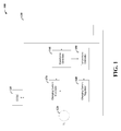
- FIG. 1 shows the block diagram of a battery charging apparatus 100, in accordance with another example embodiment.
- the battery charging apparatus 100 includes a DCDC converter 110 that converts an input DC voltage from a source 120 into a DC current to charge a battery 130.
- An impedance detection circuit 140 detects impedance characteristics of the battery 130, and a temperature estimation circuit 150 estimates the temperature of the battery 130 based on the detected impedance.
- a charging current regulator circuit 160 regulates current based on the estimated temperature (e.g ., to prevent overheating), and a charging current modulator 170 modulates the frequency of the charging current to facilitate the impedance detection.
- the charging current modulator 170 modulates the frequency of the charging current to provide a frequency that corresponds to a zero crossing point of an imaginary part of an impedance curve as detected by the impedance detection circuit 140. This approach further facilitates accurate temperature measurement.
- the charging current regulator 160 varies the charging current according to the type of charging (e.g ., slow or fast), and/or the state of charge of the battery.
- the voltage is kept constant and the current is slowly reduced as the cells approach the full-charge state.
- the output current of the DCDC converter 110 is measured by an ammeter such as a resistor or a Hall device. The output of the ammeter is compared to a reference to control the duty cycle of the DCDC converter, with the reference being a signal to keep the current constant (I charge ).
- V max as its input.
- a minimum detector passes the correct signal to obtain a desired charging characteristic.
- FIG. 2 shows a battery management apparatus 200, in accordance with a more particular embodiment.
- the battery management apparatus 200 includes a charger 210 that drives a desired current into a battery, and a cell supervisor 220 that monitors the cell voltage(s).
- a plurality of cell supervisors such as cell supervisor 220, are implemented for each cell within a battery that is charged by charger 210.
- the charger 210 includes a DCDC converter 211 that provides an output, using voltage supply 219, to an ammeter 212 that in turn provides an output to a comparator 213.
- a low-pass filter 214 also provides an output to a comparator 215, which is also supplied with a present maximum voltage input.
- the comparator 215 provides an output to a minimum detector 216, which is fed a signal Icharge that sets a current according to a particular profile.
- a sine generator 217 generates a reference signal that his added at adder 218 to an output of the minimum detector 216, and provided as another input to the comparator 213, as a reference to control the duty cycle of the DCDC converter 211.
- the reference includes a DC component corresponding to signal I charge and an AC component generated by the sine generator 217 ( e.g., the frequency of which can be varied).
- the low-pass filter 214 ensures that the generated sine is not suppressed when the charger is in a constant-voltage mode. Once the battery voltage reaches a set maximum level, it is kept constant via the control loop that includes signal V max as its input, which is active via the control of the minimum detector 216.
- the cell supervisor 220 includes a low-pass filter 221 that is coupled to receive a signal across an individual cell 230, and provides an output to an analog-to-digital converter (ADC) 222.
- the ADC 222 provides an output to another low-pass filter 223, which provides an output indicative of the battery voltage.
- a sine (or cosine) generator 224 provides a reference signal to a synchronous demodulator 225, which also receives the output of the ADC 222 and which generates outputs indicative of real and imaginary parts of an impedance of the cell 230.
- These aspects may be used, for example, by the charger 210 to set a frequency and/or level of modulated charging current provided via the DCDC converter 211.
- the modulation of the charge current is controlled such that small modulations of the cell voltages are low enough (e.g ., 1mV or less) so as to mitigate reduction in cell lifetime.
- Temperature can be estimated via detection of impedance aspects of the cell, based upon an output of cell supervisor 220, such as described in U.S. Patent Application Serial No. 13/555,923 , which is fully incorporated herein by reference. For instance, the temperature can be ascertained for each individual cell in the system by varying the frequency of the sine and looking for a frequency at which the imaginary part of the cell impedance is zero, at which the voltage across and the current through the cell are in phase, or at an intercept point.
- the charger 210 and cell supervisor 220 can be easily integrated into one integrated circuit (IC).
- the sine generator of the charger 210 and the (co)sine generator of the cell supervisor 220 are the same component.
- functions relating to the charger and supervisor aspects can be distributed in several ICs ( e.g., with the sine generator of the charger synchronized with the (co)sine generator of the supervisor, such as described in U.S. Patent Application Serial No. 14/107,530 which is fully incorporated herein by reference.
- FIG. 3 another battery management apparatus 300 is shown, in accordance with another embodiment.
- the battery management apparatus 300 is similar to apparatus 200 as shown in Figure 2 , with a sample-and-hold (S/H) circuit 314 used in place of the low-pass filter 214 of the constant-voltage loop of the charger 210.
- S/H sample-and-hold
- Other aspects of the battery management apparatus 300 are labeled with reference numbers that are similar to those in Figure 2 (e.g., DCDC converters 211 and 311), and may thus be characterized as described with Figure 2 .
- the S/H circuit 314 takes samples synchronously with the sine wave generated by sine generator 317, and the sine wave can be effectively eliminated at its output.
- Various approaches to estimating temperature via impedance, with related frequencies of charging current are implemented to suit one or more embodiments.
- low- and mid-frequency components of impedance can be used to estimate temperatures.
- An intercept frequency at which cell impedance is real and the phase shift between alternating voltage and current is zero for different temperatures can be used as an indication of temperature.
- Such an approach may be implemented, for example, as consistent with those approaches described in L.H.J. Raijmakers, D.L.Danilov, J.P.M. van Lammeren, M.J.G. Lammers, P.H.L. Notten, "Sensorless battery temperature measurements based on electrochemical impedance spectroscopy," Journal of Power Sources (2013 ), which is fully incorporated herein by reference.
- Various embodiments are directed to detecting temperature based upon a non-zero intercept frequency of such a plot for impedance.
- the frequency at which the measurement is made is taken at a particular positive imaginary impedance value (e.g., in the inductive area of the battery's impedance).
- Observing a non-zero intercept frequency at frequencies higher than a zero intercept frequency can be used to avoid lower frequencies, which allows effects of charge transfer processes to be neglected, and to mitigate interference, as the amplitude of such interference can be smaller at higher frequencies.
- Such a non-zero intercept frequency increases with a higher positive imaginary value of the impedance, which can be used for accurate temperature gauging.
- phase shift between alternating current and voltage at a particular frequency chosen such that the imaginary part of the impedance is positive (e.g., in the inductive area of the battery's impedance).
- the phase shift is also positive, as may be facilitated by measuring in the inductive area of the impedance such that the frequencies are beyond a frequency range in which the main electrochemical storage reactions take place.
- an intercept frequency is measured as follows. A sequence of measurements is taken by first measuring the cell impedance at an arbitrary frequency. If the imaginary part of the impedance is higher than the target value (e.g., zero or non-zero), then a higher frequency is tried next. If the imaginary part of the impedance is lower than such a target value, a lower frequency is tried next. This procedure can be repeated to obtain two (or more) measurements, which can be used via interpolation to estimate temperature. In some implementations, to keep the measurement time as short as possible, two measurement frequencies are injected into the cell simultaneously.
- the target value e.g., zero or non-zero
- Two simultaneously injected frequencies can be handled by a hardware solution, such as by using the sine (or cosine) generator 224 and synchronous demodulator 225 of Figure 2 with a multiplexer, or duplicating these circuits for measuring at two different frequencies.
- a hardware solution such as by using the sine (or cosine) generator 224 and synchronous demodulator 225 of Figure 2 with a multiplexer, or duplicating these circuits for measuring at two different frequencies.
- Such an approach can be carried out by choosing two frequencies such that the intercept point found in a previous measurement is halfway between the frequencies, such as where temperature is measured at a rate higher than the inverse of the cell's thermal time constant.
- temperature estimation for ageing battery cells is calibrated with an external temperature sensor, located somewhere in the battery pack, when the battery pack is in thermal equilibrium.
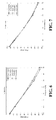
- Figures 4 and 5 show plot of non-zero intercept frequencies f(0.5) and f(1.0), as may be used in estimating temperature in accordance with one or more embodiments. Temperature is shown on the horizontal axis, with corresponding non-zero intercept frequencies on the vertical axis, for various exemplary implementations. Different frequencies can be matched to respective temperatures using such plots, using frequencies at which the imaginary part of impedance is positive, and thereby estimate temperature based on related impedance.
- Figures 6-9 show plots of phase shift at respective frequencies of about 1510 Hz, 1914 Hz, 3888 Hz and 4923 Hz, as used in estimating temperature in accordance with one or more embodiments. Temperature is shown on the horizontal axis, and phase shift between alternating current and voltage is shown on the vertical axis, for respective implementations. The exhibited correlation between phase shift and temperature can be used to estimate temperature for respective impedance, with frequencies at which the imaginary part of the impedance is positive.
- temperature estimation is carried out without using temperature sensors and associated wiring.
- measurement lag due to the thermal mass of the battery cell is reduced or eliminated, such as for fast charging applications in which the temperature of the battery may rise very quickly if something goes wrong inside the cell.
- the phase difference between current and voltage in the cell is measured and can be used alone to provide an estimation of temperature (e.g ., without necessarily knowing or detecting signal amplitude).
- one or more embodiments may be implemented in connection with various aspects such as those described in one or both of: Young-Jin Hong and Chi-Su Kim, "Modeling of the thermal behaviour of a Lithium-Ion battery pack," Advanced Automotive Battery conference 2010 ; and P.H.L. Notten, J.H.G. op het Veld, J.R.G. van Beek, "Boostcharging Li-ion batteries: A challenging new charging concept,” Journal of Power Sources (2005 ), which are fully incorporated herein by reference.
- a “block” (also sometimes “logic circuitry” or “module”) is a circuit that carries out one or more of these or related operations/activities (e.g ., controlling the modulation of frequency of a charging current, estimating impedance, or controlling an amount of charging current).
- one or more modules are discrete logic circuits or programmable logic circuits configured and arranged for implementing these operations/activities, as in the circuit modules shown in Figure 1 .
- such a programmable circuit is one or more computer circuits programmed to execute a set (or sets) of instructions (and/or configuration data).
- the instructions (and/or configuration data) can be in the form of firmware or software stored in and accessible from a memory (circuit).
- first and second modules include a combination of a CPU hardware-based circuit and a set of instructions in the form of firmware, where the first module includes a first CPU hardware circuit with one set of instructions and the second module includes a second CPU hardware circuit with another set of instructions.
- Certain embodiments are directed to a computer program product (e.g ., nonvolatile memory device), which includes a machine or computer-readable medium having stored thereon instructions which may be executed by a computer (or other electronic device) to perform these operations/activities.
- a computer program product e.g ., nonvolatile memory device
Landscapes
- Engineering & Computer Science (AREA)
- Power Engineering (AREA)
- Manufacturing & Machinery (AREA)
- Chemical & Material Sciences (AREA)
- Chemical Kinetics & Catalysis (AREA)
- Electrochemistry (AREA)
- General Chemical & Material Sciences (AREA)
- Secondary Cells (AREA)
- Charge And Discharge Circuits For Batteries Or The Like (AREA)
- Physics & Mathematics (AREA)
- General Physics & Mathematics (AREA)
Applications Claiming Priority (1)
| Application Number | Priority Date | Filing Date | Title |
|---|---|---|---|
| US14/244,610 US9673657B2 (en) | 2014-04-03 | 2014-04-03 | Battery charging apparatus and approach |
Publications (1)
| Publication Number | Publication Date |
|---|---|
| EP2933898A1 true EP2933898A1 (de) | 2015-10-21 |
Family
ID=52697323
Family Applications (1)
| Application Number | Title | Priority Date | Filing Date |
|---|---|---|---|
| EP15160598.7A Withdrawn EP2933898A1 (de) | 2014-04-03 | 2015-03-24 | Batterieladevorrichtung und -ansatz |
Country Status (3)
| Country | Link |
|---|---|
| US (1) | US9673657B2 (de) |
| EP (1) | EP2933898A1 (de) |
| KR (1) | KR101783669B1 (de) |
Cited By (7)
| Publication number | Priority date | Publication date | Assignee | Title |
|---|---|---|---|---|
| CN107425555A (zh) * | 2016-05-24 | 2017-12-01 | 比亚迪股份有限公司 | 充电保护方法、充电保护装置及便携式充电装置 |
| EP3261213A1 (de) * | 2016-06-20 | 2017-12-27 | Ningde Amperex Technology Limited | Verfahren und vorrichtung zum laden einer batterie |
| EP3432439A1 (de) * | 2017-07-20 | 2019-01-23 | Zhejiang Godsend Power Technology Co., Ltd | Systeme und steuerungsvorrichtungen zum laden und entladen einer lithium-ionen-batterie und zugehöriges verfahren |
| WO2021257593A1 (en) | 2020-06-16 | 2021-12-23 | Black & Decker Inc. | Battery charger |
| WO2024114969A1 (en) * | 2022-11-30 | 2024-06-06 | Cirrus Logic International Semiconductor Limited | A system for controlling charging of a battery |
| EP4668537A1 (de) * | 2024-06-17 | 2025-12-24 | Black & Decker, Inc. | System und verfahren zur überwachung eines batteriepacks |
| US12556021B2 (en) | 2020-06-16 | 2026-02-17 | Black & Decker Inc. | System and method for charging a battery pack |
Families Citing this family (20)
| Publication number | Priority date | Publication date | Assignee | Title |
|---|---|---|---|---|
| DE102015225389B4 (de) * | 2015-12-16 | 2018-02-01 | Audi Ag | Temperaturermittlung bei einer Fahrzeugbatterie |
| KR102574083B1 (ko) * | 2016-01-12 | 2023-09-04 | 삼성전자주식회사 | 배터리 관리 장치 및 방법 |
| GB2552777B (en) | 2016-07-21 | 2022-06-08 | Petalite Ltd | A battery charging system and method |
| EP3566259B1 (de) * | 2017-01-09 | 2023-03-08 | Milwaukee Electric Tool Corporation | Batteriepack |
| US10481214B2 (en) * | 2017-01-30 | 2019-11-19 | Infineon Technologies Ag | Battery temperature detection |
| JP6806002B2 (ja) * | 2017-08-24 | 2020-12-23 | トヨタ自動車株式会社 | 温度推定装置 |
| KR102476898B1 (ko) | 2018-01-02 | 2022-12-13 | 엘지전자 주식회사 | 충전 장치 |
| US11196269B2 (en) * | 2018-07-05 | 2021-12-07 | The Johns Hopkins University | Battery cell protection system |
| CN114269591A (zh) * | 2019-08-21 | 2022-04-01 | 沃尔沃卡车集团 | 用于优化车辆的电力推进系统的能量管理的方法 |
| EP4027431B1 (de) * | 2019-09-06 | 2026-03-18 | Nuvoton Technology Corporation Japan | Stromspeichersystem, stromspeichervorrichtung und ladeverfahren |
| DE102019127910A1 (de) * | 2019-10-16 | 2021-04-22 | Bayerische Motoren Werke Aktiengesellschaft | Verfahren und vorrichtung zur überwachung einer elektrochemischen energiespeicherzelle sowie fahrzeug |
| DE102019133921A1 (de) * | 2019-12-11 | 2021-06-17 | Bayerische Motoren Werke Aktiengesellschaft | Verfahren, Vorrichtung, System, Elektrofahrzeug, Computerprogramm und Speichermedium zum Laden oder Entladen einer Zelle eines elektrischen Energiespeichers |
| KR102893180B1 (ko) * | 2021-01-28 | 2025-12-01 | 컨템포러리 엠퍼렉스 테크놀로지 (홍콩) 리미티드 | 충전 방법, 전원 배터리의 배터리 관리 시스템 및 충전 파일 |
| KR102644606B1 (ko) * | 2021-01-28 | 2024-03-08 | 컨템포러리 엠퍼렉스 테크놀로지 씨오., 리미티드 | 충전 방법 및 전력 변환 장치 |
| WO2022261910A1 (zh) * | 2021-06-17 | 2022-12-22 | 宁德时代新能源科技股份有限公司 | 充电控制方法及装置、电池管理系统、可读存储介质 |
| WO2023028789A1 (zh) * | 2021-08-30 | 2023-03-09 | 宁德时代新能源科技股份有限公司 | 温度确定方法与电流阈值确定方法、电池管理系统 |
| JP2024010570A (ja) * | 2022-07-12 | 2024-01-24 | 株式会社デンソー | 2次電池の熱暴走予兆検知装置、及び2次電池の熱暴走予兆検知方法 |
| KR20250049334A (ko) * | 2022-08-09 | 2025-04-11 | 이온트라 인코포레이티드 | 배터리 충전을 위한 최적화된 에너지 신호를 생성하는 모델 예측 제어기 아키텍처 및 방법 |
| KR102893095B1 (ko) * | 2022-10-27 | 2025-12-03 | (주)에이프로 | 배터리 충전특성을 향상시킨 배터리 활성화 장치 |
| CN116499613A (zh) * | 2023-06-02 | 2023-07-28 | 北京索科曼正卓智能电气有限公司 | 测量锂电池内部温度的方法、装置、设备和可读存储介质 |
Citations (4)
| Publication number | Priority date | Publication date | Assignee | Title |
|---|---|---|---|---|
| EP1548453A1 (de) * | 2002-07-12 | 2005-06-29 | Toyota Jidosha Kabushiki Kaisha | SCHüTZER FüR DEN BATTERIELADUNGSZUSTAND |
| JP2008298786A (ja) * | 2001-08-13 | 2008-12-11 | Hitachi Maxell Ltd | 電池容量検出方法 |
| WO2011004249A2 (en) * | 2009-07-08 | 2011-01-13 | Toyota Jidosha Kabushiki Kaisha | Secondary battery temperature-estimating apparatus |
| WO2011122946A2 (en) * | 2010-04-02 | 2011-10-06 | Epyon B.V. | Method and device for charging a battery and battery charger |
Family Cites Families (11)
| Publication number | Priority date | Publication date | Assignee | Title |
|---|---|---|---|---|
| JP2010243481A (ja) | 2009-03-18 | 2010-10-28 | National Institute Of Advanced Industrial Science & Technology | 二次電池の温度に関する状態を判定する方法、判定装置および判定プログラム |
| WO2012054473A1 (en) * | 2010-10-18 | 2012-04-26 | Johns Hopkins University | Battery phase meter to determine internal temperatures of lithium-ion rechargeable cells under charge and discharge |
| EP2447728B1 (de) | 2010-10-28 | 2013-06-19 | Nxp B.V. | Messanordnung für Impedanzspektroskopie in Batteriezellen |
| US9128165B2 (en) | 2011-05-04 | 2015-09-08 | Datang Nxp Semiconductors Co., Ltd. | Battery cell impedance measurement method and apparatus |
| US9252465B2 (en) * | 2011-05-24 | 2016-02-02 | GM Global Technology Operations LLC | Battery recharge estimator using battery impedance response |
| US9575135B2 (en) | 2011-06-01 | 2017-02-21 | Datang Nxp Semiconductors Co., Ltd. | Battery monitoring circuit, apparatus and method |
| KR101609076B1 (ko) | 2011-08-01 | 2016-04-04 | 알프스 그린 디바이스 가부시키가이샤 | 축전 장치 온도 측정 방법 |
| US9322884B2 (en) * | 2012-01-06 | 2016-04-26 | Industrial Technology Research Institute | Impedance analyzing device |
| US8994340B2 (en) * | 2012-05-15 | 2015-03-31 | GM Global Technology Operations LLC | Cell temperature and degradation measurement in lithium ion battery systems using cell voltage and pack current measurement and the relation of cell impedance to temperature based on signal given by the power inverter |
| US9035619B2 (en) | 2012-05-24 | 2015-05-19 | Datang Nxp Semiconductors Co., Ltd. | Battery cell temperature detection |
| US20150102943A1 (en) | 2013-10-10 | 2015-04-16 | Datang Nxp Semiconductors Co., Ltd. | Daisy-chain communication bus and protocol |
-
2014
- 2014-04-03 US US14/244,610 patent/US9673657B2/en not_active Expired - Fee Related
-
2015
- 2015-03-24 EP EP15160598.7A patent/EP2933898A1/de not_active Withdrawn
- 2015-04-03 KR KR1020150047398A patent/KR101783669B1/ko not_active Expired - Fee Related
Patent Citations (4)
| Publication number | Priority date | Publication date | Assignee | Title |
|---|---|---|---|---|
| JP2008298786A (ja) * | 2001-08-13 | 2008-12-11 | Hitachi Maxell Ltd | 電池容量検出方法 |
| EP1548453A1 (de) * | 2002-07-12 | 2005-06-29 | Toyota Jidosha Kabushiki Kaisha | SCHüTZER FüR DEN BATTERIELADUNGSZUSTAND |
| WO2011004249A2 (en) * | 2009-07-08 | 2011-01-13 | Toyota Jidosha Kabushiki Kaisha | Secondary battery temperature-estimating apparatus |
| WO2011122946A2 (en) * | 2010-04-02 | 2011-10-06 | Epyon B.V. | Method and device for charging a battery and battery charger |
Non-Patent Citations (3)
| Title |
|---|
| L.H.J. RAIJMAKERS; D.L.DANILOV; J.P.M. VAN LAMMEREN; M.J.G. LAMMERS; P.H.L. NOTTEN: "Sensorless battery temperature measurements based on electrochemical impedance spectroscopy", JOURNAL OF POWER SOURCES, 2013 |
| P.H.L. NOTTEN; J.H.G. OP HET VELD; J.R.G. VAN BEEK: "Boostcharging Li-ion batteries: A challenging new charging concept", JOURNAL OF POWER SOURCES, 2005 |
| YOUNG-JIN HONG; CHI-SU KIM: "Modeling of the thermal behaviour of a Lithium-Ion battery pack", ADVANCED AUTOMOTIVE BATTERY CONFERENCE, 2010 |
Cited By (12)
| Publication number | Priority date | Publication date | Assignee | Title |
|---|---|---|---|---|
| CN107425555A (zh) * | 2016-05-24 | 2017-12-01 | 比亚迪股份有限公司 | 充电保护方法、充电保护装置及便携式充电装置 |
| EP3261213A1 (de) * | 2016-06-20 | 2017-12-27 | Ningde Amperex Technology Limited | Verfahren und vorrichtung zum laden einer batterie |
| US10135279B2 (en) | 2016-06-20 | 2018-11-20 | Ningde Amperex Technology Limited | Method and apparatus of battery charging |
| EP3432439A1 (de) * | 2017-07-20 | 2019-01-23 | Zhejiang Godsend Power Technology Co., Ltd | Systeme und steuerungsvorrichtungen zum laden und entladen einer lithium-ionen-batterie und zugehöriges verfahren |
| JP2019021608A (ja) * | 2017-07-20 | 2019-02-07 | ゼジャン・ゴッドセンド・パワー・テクノロジー・カンパニー・リミテッド | リチウムイオン電池の充放電システム、制御装置及び関連方法 |
| US10256512B2 (en) | 2017-07-20 | 2019-04-09 | Zhejiang Godsend Power Technology Co., Ltd. | Systems and control devices for charging and discharging lithium-ion battery, and relevant methods |
| WO2021257593A1 (en) | 2020-06-16 | 2021-12-23 | Black & Decker Inc. | Battery charger |
| EP4165421A4 (de) * | 2020-06-16 | 2024-07-24 | Black & Decker Inc. | Batterieladegerät |
| US12556020B2 (en) | 2020-06-16 | 2026-02-17 | Black & Decker Inc. | System and method for charging a battery pack |
| US12556021B2 (en) | 2020-06-16 | 2026-02-17 | Black & Decker Inc. | System and method for charging a battery pack |
| WO2024114969A1 (en) * | 2022-11-30 | 2024-06-06 | Cirrus Logic International Semiconductor Limited | A system for controlling charging of a battery |
| EP4668537A1 (de) * | 2024-06-17 | 2025-12-24 | Black & Decker, Inc. | System und verfahren zur überwachung eines batteriepacks |
Also Published As
| Publication number | Publication date |
|---|---|
| US9673657B2 (en) | 2017-06-06 |
| KR20150115668A (ko) | 2015-10-14 |
| US20150288213A1 (en) | 2015-10-08 |
| KR101783669B1 (ko) | 2017-11-06 |
Similar Documents
| Publication | Publication Date | Title |
|---|---|---|
| US9673657B2 (en) | Battery charging apparatus and approach | |
| EP2667166B1 (de) | Batterietemperaturerkennung | |
| US11929468B2 (en) | Method and apparatus for charging battery | |
| US10459034B2 (en) | Method and apparatus for estimating state of health (SOH) of battery | |
| CN102066964B (zh) | 用于确定蓄电池充电状态的系统和方法 | |
| KR102200550B1 (ko) | 이차 전지의 충전 상태를 추정하기 위한 장치 | |
| US10749220B2 (en) | Battery control apparatus and battery control system | |
| Bockrath et al. | State of charge estimation using recurrent neural networks with long short-term memory for lithium-ion batteries | |
| JP6859585B2 (ja) | バッテリーの電力限界を決定するための方法及びバッテリー管理システム | |
| CN111180813A (zh) | 近似基于电化学电池模型给锂离子电池快充电算法的方法 | |
| JP6101714B2 (ja) | 電池制御装置、電池システム | |
| US20170176544A1 (en) | Method for estimating degradation of rechargeable battery, degradation estimation circuit, electronic apparatus and vehicle including same | |
| US10393814B2 (en) | Secondary battery state detection device and secondary battery state detection method | |
| US11095130B2 (en) | Power storage apparatus for estimating an open-circuit voltage | |
| US10444296B2 (en) | Control device, control method, and recording medium | |
| JP2016508014A5 (de) | ||
| JP2015039279A (ja) | バッテリを制御するためのシステムおよび方法 | |
| CN104656029A (zh) | 一种估算动力电池剩余容量的系统及方法 | |
| Avvari et al. | Experimental set-up and procedures to test and validate battery fuel gauge algorithms | |
| KR20160040887A (ko) | 배터리 셀 내부 저항 측정 장치 및 방법 | |
| WO2014105806A1 (en) | System and method for selective estimation of battery state with reference to persistence of excitation and current magnitude | |
| US20150260796A1 (en) | Battery cell state-of-charge estimation and readjustment method | |
| CN107923951B (zh) | 电池充电状态推断装置 | |
| CN106208173B (zh) | 电池充电装置和方法 | |
| JP2016015840A (ja) | 充電電流制御方法 |
Legal Events
| Date | Code | Title | Description |
|---|---|---|---|
| PUAI | Public reference made under article 153(3) epc to a published international application that has entered the european phase |
Free format text: ORIGINAL CODE: 0009012 |
|
| AK | Designated contracting states |
Kind code of ref document: A1 Designated state(s): AL AT BE BG CH CY CZ DE DK EE ES FI FR GB GR HR HU IE IS IT LI LT LU LV MC MK MT NL NO PL PT RO RS SE SI SK SM TR |
|
| AX | Request for extension of the european patent |
Extension state: BA ME |
|
| 17P | Request for examination filed |
Effective date: 20160421 |
|
| RBV | Designated contracting states (corrected) |
Designated state(s): AL AT BE BG CH CY CZ DE DK EE ES FI FR GB GR HR HU IE IS IT LI LT LU LV MC MK MT NL NO PL PT RO RS SE SI SK SM TR |
|
| 17Q | First examination report despatched |
Effective date: 20160607 |
|
| STAA | Information on the status of an ep patent application or granted ep patent |
Free format text: STATUS: EXAMINATION IS IN PROGRESS |
|
| STAA | Information on the status of an ep patent application or granted ep patent |
Free format text: STATUS: THE APPLICATION IS DEEMED TO BE WITHDRAWN |
|
| 18D | Application deemed to be withdrawn |
Effective date: 20190905 |