EP2933870B1 - Heat sink having two separated flow channels - Google Patents
Heat sink having two separated flow channels Download PDFInfo
- Publication number
- EP2933870B1 EP2933870B1 EP14853248.4A EP14853248A EP2933870B1 EP 2933870 B1 EP2933870 B1 EP 2933870B1 EP 14853248 A EP14853248 A EP 14853248A EP 2933870 B1 EP2933870 B1 EP 2933870B1
- Authority
- EP
- European Patent Office
- Prior art keywords
- heat sink
- cooling
- battery
- secondary battery
- present disclosure
- Prior art date
- Legal status (The legal status is an assumption and is not a legal conclusion. Google has not performed a legal analysis and makes no representation as to the accuracy of the status listed.)
- Active
Links
- 238000001816 cooling Methods 0.000 claims description 71
- 239000003507 refrigerant Substances 0.000 claims description 3
- 239000012528 membrane Substances 0.000 description 12
- PXHVJJICTQNCMI-UHFFFAOYSA-N Nickel Chemical compound [Ni] PXHVJJICTQNCMI-UHFFFAOYSA-N 0.000 description 8
- -1 aluminum-cadmium Chemical compound 0.000 description 7
- OKTJSMMVPCPJKN-UHFFFAOYSA-N Carbon Chemical compound [C] OKTJSMMVPCPJKN-UHFFFAOYSA-N 0.000 description 6
- 229910052799 carbon Inorganic materials 0.000 description 5
- 239000002826 coolant Substances 0.000 description 5
- 239000010954 inorganic particle Substances 0.000 description 5
- RTAQQCXQSZGOHL-UHFFFAOYSA-N Titanium Chemical compound [Ti] RTAQQCXQSZGOHL-UHFFFAOYSA-N 0.000 description 4
- 229910052782 aluminium Inorganic materials 0.000 description 4
- 239000007773 negative electrode material Substances 0.000 description 4
- 229910052759 nickel Inorganic materials 0.000 description 4
- 239000007774 positive electrode material Substances 0.000 description 4
- 239000010935 stainless steel Substances 0.000 description 4
- 229910001220 stainless steel Inorganic materials 0.000 description 4
- 239000010936 titanium Substances 0.000 description 4
- 229910052719 titanium Inorganic materials 0.000 description 4
- XAGFODPZIPBFFR-UHFFFAOYSA-N aluminium Chemical compound [Al] XAGFODPZIPBFFR-UHFFFAOYSA-N 0.000 description 3
- 230000000694 effects Effects 0.000 description 3
- 238000004146 energy storage Methods 0.000 description 3
- 239000000463 material Substances 0.000 description 3
- ODINCKMPIJJUCX-UHFFFAOYSA-N Calcium oxide Chemical compound [Ca]=O ODINCKMPIJJUCX-UHFFFAOYSA-N 0.000 description 2
- RYGMFSIKBFXOCR-UHFFFAOYSA-N Copper Chemical compound [Cu] RYGMFSIKBFXOCR-UHFFFAOYSA-N 0.000 description 2
- CPLXHLVBOLITMK-UHFFFAOYSA-N Magnesium oxide Chemical compound [Mg]=O CPLXHLVBOLITMK-UHFFFAOYSA-N 0.000 description 2
- 229910020294 Pb(Zr,Ti)O3 Inorganic materials 0.000 description 2
- 229910020351 Pb1-xLaxZr1-yTiyO3 Inorganic materials 0.000 description 2
- 229910020345 Pb1−xLaxZr1−yTiyO3 Inorganic materials 0.000 description 2
- BQCADISMDOOEFD-UHFFFAOYSA-N Silver Chemical compound [Ag] BQCADISMDOOEFD-UHFFFAOYSA-N 0.000 description 2
- GWEVSGVZZGPLCZ-UHFFFAOYSA-N Titan oxide Chemical compound O=[Ti]=O GWEVSGVZZGPLCZ-UHFFFAOYSA-N 0.000 description 2
- XLOMVQKBTHCTTD-UHFFFAOYSA-N Zinc monoxide Chemical compound [Zn]=O XLOMVQKBTHCTTD-UHFFFAOYSA-N 0.000 description 2
- MCMNRKCIXSYSNV-UHFFFAOYSA-N Zirconium dioxide Chemical compound O=[Zr]=O MCMNRKCIXSYSNV-UHFFFAOYSA-N 0.000 description 2
- 239000011149 active material Substances 0.000 description 2
- 229920002301 cellulose acetate Polymers 0.000 description 2
- 239000011248 coating agent Substances 0.000 description 2
- 238000000576 coating method Methods 0.000 description 2
- 239000004020 conductor Substances 0.000 description 2
- 229910052802 copper Inorganic materials 0.000 description 2
- 239000010949 copper Substances 0.000 description 2
- 238000010586 diagram Methods 0.000 description 2
- 238000007599 discharging Methods 0.000 description 2
- 238000001035 drying Methods 0.000 description 2
- 238000005304 joining Methods 0.000 description 2
- 229910052744 lithium Inorganic materials 0.000 description 2
- 229910052751 metal Inorganic materials 0.000 description 2
- 239000002184 metal Substances 0.000 description 2
- 238000000034 method Methods 0.000 description 2
- 239000000203 mixture Substances 0.000 description 2
- 238000012986 modification Methods 0.000 description 2
- 230000004048 modification Effects 0.000 description 2
- 230000002093 peripheral effect Effects 0.000 description 2
- 229920000131 polyvinylidene Polymers 0.000 description 2
- 229910052709 silver Inorganic materials 0.000 description 2
- 239000004332 silver Substances 0.000 description 2
- 239000000126 substance Substances 0.000 description 2
- XOLBLPGZBRYERU-UHFFFAOYSA-N tin dioxide Chemical compound O=[Sn]=O XOLBLPGZBRYERU-UHFFFAOYSA-N 0.000 description 2
- 238000003466 welding Methods 0.000 description 2
- KXJGSNRAQWDDJT-UHFFFAOYSA-N 1-acetyl-5-bromo-2h-indol-3-one Chemical compound BrC1=CC=C2N(C(=O)C)CC(=O)C2=C1 KXJGSNRAQWDDJT-UHFFFAOYSA-N 0.000 description 1
- XCKPLVGWGCWOMD-YYEYMFTQSA-N 3-[[(2r,3r,4s,5r,6r)-6-[(2s,3s,4r,5r)-3,4-bis(2-cyanoethoxy)-2,5-bis(2-cyanoethoxymethyl)oxolan-2-yl]oxy-3,4,5-tris(2-cyanoethoxy)oxan-2-yl]methoxy]propanenitrile Chemical compound N#CCCO[C@H]1[C@H](OCCC#N)[C@@H](COCCC#N)O[C@@]1(COCCC#N)O[C@@H]1[C@H](OCCC#N)[C@@H](OCCC#N)[C@H](OCCC#N)[C@@H](COCCC#N)O1 XCKPLVGWGCWOMD-YYEYMFTQSA-N 0.000 description 1
- BMTAFVWTTFSTOG-UHFFFAOYSA-N Butylate Chemical compound CCSC(=O)N(CC(C)C)CC(C)C BMTAFVWTTFSTOG-UHFFFAOYSA-N 0.000 description 1
- 229920000049 Carbon (fiber) Polymers 0.000 description 1
- 229920002134 Carboxymethyl cellulose Polymers 0.000 description 1
- 229910000925 Cd alloy Inorganic materials 0.000 description 1
- 229920008347 Cellulose acetate propionate Polymers 0.000 description 1
- 229910000733 Li alloy Inorganic materials 0.000 description 1
- 229910032387 LiCoO2 Inorganic materials 0.000 description 1
- 229910052493 LiFePO4 Inorganic materials 0.000 description 1
- 229910002993 LiMnO2 Inorganic materials 0.000 description 1
- 229910003005 LiNiO2 Inorganic materials 0.000 description 1
- WHXSMMKQMYFTQS-UHFFFAOYSA-N Lithium Chemical compound [Li] WHXSMMKQMYFTQS-UHFFFAOYSA-N 0.000 description 1
- HBBGRARXTFLTSG-UHFFFAOYSA-N Lithium ion Chemical compound [Li+] HBBGRARXTFLTSG-UHFFFAOYSA-N 0.000 description 1
- 229910002097 Lithium manganese(III,IV) oxide Inorganic materials 0.000 description 1
- 229910015282 Ni1−x−yCoxMy Inorganic materials 0.000 description 1
- 229910020213 PB(Mg3Nb2/3)O3-PbTiO3 Inorganic materials 0.000 description 1
- 229910020210 Pb(Mg3Nb2/3)O3—PbTiO3 Inorganic materials 0.000 description 1
- 229920003171 Poly (ethylene oxide) Polymers 0.000 description 1
- 239000004696 Poly ether ether ketone Substances 0.000 description 1
- 229930182556 Polyacetal Natural products 0.000 description 1
- 239000004952 Polyamide Substances 0.000 description 1
- 239000004695 Polyether sulfone Substances 0.000 description 1
- 239000004642 Polyimide Substances 0.000 description 1
- 229920000265 Polyparaphenylene Polymers 0.000 description 1
- 239000004721 Polyphenylene oxide Substances 0.000 description 1
- 239000004373 Pullulan Substances 0.000 description 1
- 229920001218 Pullulan Polymers 0.000 description 1
- 229910002370 SrTiO3 Inorganic materials 0.000 description 1
- XECAHXYUAAWDEL-UHFFFAOYSA-N acrylonitrile butadiene styrene Chemical compound C=CC=C.C=CC#N.C=CC1=CC=CC=C1 XECAHXYUAAWDEL-UHFFFAOYSA-N 0.000 description 1
- 239000004676 acrylonitrile butadiene styrene Substances 0.000 description 1
- 229920000122 acrylonitrile butadiene styrene Polymers 0.000 description 1
- PNEYBMLMFCGWSK-UHFFFAOYSA-N aluminium oxide Inorganic materials [O-2].[O-2].[O-2].[Al+3].[Al+3] PNEYBMLMFCGWSK-UHFFFAOYSA-N 0.000 description 1
- 229910003481 amorphous carbon Inorganic materials 0.000 description 1
- 230000000712 assembly Effects 0.000 description 1
- 238000000429 assembly Methods 0.000 description 1
- 229910002113 barium titanate Inorganic materials 0.000 description 1
- 239000006227 byproduct Substances 0.000 description 1
- 239000004917 carbon fiber Substances 0.000 description 1
- 239000002388 carbon-based active material Substances 0.000 description 1
- 239000003575 carbonaceous material Substances 0.000 description 1
- CETPSERCERDGAM-UHFFFAOYSA-N ceric oxide Chemical compound O=[Ce]=O CETPSERCERDGAM-UHFFFAOYSA-N 0.000 description 1
- 229910000422 cerium(IV) oxide Inorganic materials 0.000 description 1
- 239000003610 charcoal Substances 0.000 description 1
- 239000000470 constituent Substances 0.000 description 1
- 229910052593 corundum Inorganic materials 0.000 description 1
- 230000006866 deterioration Effects 0.000 description 1
- 238000003487 electrochemical reaction Methods 0.000 description 1
- 239000008151 electrolyte solution Substances 0.000 description 1
- 239000005038 ethylene vinyl acetate Substances 0.000 description 1
- 239000002803 fossil fuel Substances 0.000 description 1
- CJNBYAVZURUTKZ-UHFFFAOYSA-N hafnium(iv) oxide Chemical compound O=[Hf]=O CJNBYAVZURUTKZ-UHFFFAOYSA-N 0.000 description 1
- 235000015110 jellies Nutrition 0.000 description 1
- 239000008274 jelly Substances 0.000 description 1
- 239000001989 lithium alloy Substances 0.000 description 1
- 229910001416 lithium ion Inorganic materials 0.000 description 1
- 229910052748 manganese Inorganic materials 0.000 description 1
- 229910044991 metal oxide Inorganic materials 0.000 description 1
- 150000004706 metal oxides Chemical class 0.000 description 1
- 229920001200 poly(ethylene-vinyl acetate) Polymers 0.000 description 1
- 229920002239 polyacrylonitrile Polymers 0.000 description 1
- 229920002647 polyamide Polymers 0.000 description 1
- 229920001707 polybutylene terephthalate Polymers 0.000 description 1
- 229920000728 polyester Polymers 0.000 description 1
- 229920006393 polyether sulfone Polymers 0.000 description 1
- 229920002530 polyetherether ketone Polymers 0.000 description 1
- 229920000139 polyethylene terephthalate Polymers 0.000 description 1
- 239000005020 polyethylene terephthalate Substances 0.000 description 1
- 229920001721 polyimide Polymers 0.000 description 1
- 229920005597 polymer membrane Polymers 0.000 description 1
- 229920000098 polyolefin Polymers 0.000 description 1
- 229920006324 polyoxymethylene Polymers 0.000 description 1
- 229920006380 polyphenylene oxide Polymers 0.000 description 1
- 229920002689 polyvinyl acetate Polymers 0.000 description 1
- 239000011118 polyvinyl acetate Substances 0.000 description 1
- 229920000036 polyvinylpyrrolidone Polymers 0.000 description 1
- 239000001267 polyvinylpyrrolidone Substances 0.000 description 1
- 235000013855 polyvinylpyrrolidone Nutrition 0.000 description 1
- 239000011148 porous material Substances 0.000 description 1
- 239000000047 product Substances 0.000 description 1
- 235000019423 pullulan Nutrition 0.000 description 1
- 238000005096 rolling process Methods 0.000 description 1
- 239000000243 solution Substances 0.000 description 1
- 229910052712 strontium Inorganic materials 0.000 description 1
- 229910001845 yogo sapphire Inorganic materials 0.000 description 1
- RUDFQVOCFDJEEF-UHFFFAOYSA-N yttrium(III) oxide Inorganic materials [O-2].[O-2].[O-2].[Y+3].[Y+3] RUDFQVOCFDJEEF-UHFFFAOYSA-N 0.000 description 1
Images


Classifications
-
- H—ELECTRICITY
- H01—ELECTRIC ELEMENTS
- H01M—PROCESSES OR MEANS, e.g. BATTERIES, FOR THE DIRECT CONVERSION OF CHEMICAL ENERGY INTO ELECTRICAL ENERGY
- H01M10/00—Secondary cells; Manufacture thereof
- H01M10/60—Heating or cooling; Temperature control
- H01M10/65—Means for temperature control structurally associated with the cells
- H01M10/655—Solid structures for heat exchange or heat conduction
- H01M10/6556—Solid parts with flow channel passages or pipes for heat exchange
-
- H—ELECTRICITY
- H01—ELECTRIC ELEMENTS
- H01M—PROCESSES OR MEANS, e.g. BATTERIES, FOR THE DIRECT CONVERSION OF CHEMICAL ENERGY INTO ELECTRICAL ENERGY
- H01M10/00—Secondary cells; Manufacture thereof
- H01M10/60—Heating or cooling; Temperature control
-
- B—PERFORMING OPERATIONS; TRANSPORTING
- B60—VEHICLES IN GENERAL
- B60L—PROPULSION OF ELECTRICALLY-PROPELLED VEHICLES; SUPPLYING ELECTRIC POWER FOR AUXILIARY EQUIPMENT OF ELECTRICALLY-PROPELLED VEHICLES; ELECTRODYNAMIC BRAKE SYSTEMS FOR VEHICLES IN GENERAL; MAGNETIC SUSPENSION OR LEVITATION FOR VEHICLES; MONITORING OPERATING VARIABLES OF ELECTRICALLY-PROPELLED VEHICLES; ELECTRIC SAFETY DEVICES FOR ELECTRICALLY-PROPELLED VEHICLES
- B60L53/00—Methods of charging batteries, specially adapted for electric vehicles; Charging stations or on-board charging equipment therefor; Exchange of energy storage elements in electric vehicles
-
- B—PERFORMING OPERATIONS; TRANSPORTING
- B60—VEHICLES IN GENERAL
- B60L—PROPULSION OF ELECTRICALLY-PROPELLED VEHICLES; SUPPLYING ELECTRIC POWER FOR AUXILIARY EQUIPMENT OF ELECTRICALLY-PROPELLED VEHICLES; ELECTRODYNAMIC BRAKE SYSTEMS FOR VEHICLES IN GENERAL; MAGNETIC SUSPENSION OR LEVITATION FOR VEHICLES; MONITORING OPERATING VARIABLES OF ELECTRICALLY-PROPELLED VEHICLES; ELECTRIC SAFETY DEVICES FOR ELECTRICALLY-PROPELLED VEHICLES
- B60L58/00—Methods or circuit arrangements for monitoring or controlling batteries or fuel cells, specially adapted for electric vehicles
- B60L58/10—Methods or circuit arrangements for monitoring or controlling batteries or fuel cells, specially adapted for electric vehicles for monitoring or controlling batteries
- B60L58/18—Methods or circuit arrangements for monitoring or controlling batteries or fuel cells, specially adapted for electric vehicles for monitoring or controlling batteries of two or more battery modules
- B60L58/21—Methods or circuit arrangements for monitoring or controlling batteries or fuel cells, specially adapted for electric vehicles for monitoring or controlling batteries of two or more battery modules having the same nominal voltage
-
- H—ELECTRICITY
- H01—ELECTRIC ELEMENTS
- H01M—PROCESSES OR MEANS, e.g. BATTERIES, FOR THE DIRECT CONVERSION OF CHEMICAL ENERGY INTO ELECTRICAL ENERGY
- H01M10/00—Secondary cells; Manufacture thereof
- H01M10/42—Methods or arrangements for servicing or maintenance of secondary cells or secondary half-cells
- H01M10/425—Structural combination with electronic components, e.g. electronic circuits integrated to the outside of the casing
-
- H—ELECTRICITY
- H01—ELECTRIC ELEMENTS
- H01M—PROCESSES OR MEANS, e.g. BATTERIES, FOR THE DIRECT CONVERSION OF CHEMICAL ENERGY INTO ELECTRICAL ENERGY
- H01M10/00—Secondary cells; Manufacture thereof
- H01M10/42—Methods or arrangements for servicing or maintenance of secondary cells or secondary half-cells
- H01M10/44—Methods for charging or discharging
- H01M10/441—Methods for charging or discharging for several batteries or cells simultaneously or sequentially
-
- H—ELECTRICITY
- H01—ELECTRIC ELEMENTS
- H01M—PROCESSES OR MEANS, e.g. BATTERIES, FOR THE DIRECT CONVERSION OF CHEMICAL ENERGY INTO ELECTRICAL ENERGY
- H01M10/00—Secondary cells; Manufacture thereof
- H01M10/60—Heating or cooling; Temperature control
- H01M10/61—Types of temperature control
- H01M10/613—Cooling or keeping cold
-
- H—ELECTRICITY
- H01—ELECTRIC ELEMENTS
- H01M—PROCESSES OR MEANS, e.g. BATTERIES, FOR THE DIRECT CONVERSION OF CHEMICAL ENERGY INTO ELECTRICAL ENERGY
- H01M10/00—Secondary cells; Manufacture thereof
- H01M10/60—Heating or cooling; Temperature control
- H01M10/65—Means for temperature control structurally associated with the cells
- H01M10/655—Solid structures for heat exchange or heat conduction
- H01M10/6551—Surfaces specially adapted for heat dissipation or radiation, e.g. fins or coatings
-
- H—ELECTRICITY
- H01—ELECTRIC ELEMENTS
- H01M—PROCESSES OR MEANS, e.g. BATTERIES, FOR THE DIRECT CONVERSION OF CHEMICAL ENERGY INTO ELECTRICAL ENERGY
- H01M10/00—Secondary cells; Manufacture thereof
- H01M10/60—Heating or cooling; Temperature control
- H01M10/65—Means for temperature control structurally associated with the cells
- H01M10/655—Solid structures for heat exchange or heat conduction
- H01M10/6554—Rods or plates
- H01M10/6555—Rods or plates arranged between the cells
-
- H—ELECTRICITY
- H02—GENERATION; CONVERSION OR DISTRIBUTION OF ELECTRIC POWER
- H02J—CIRCUIT ARRANGEMENTS OR SYSTEMS FOR SUPPLYING OR DISTRIBUTING ELECTRIC POWER; SYSTEMS FOR STORING ELECTRIC ENERGY
- H02J7/00—Circuit arrangements for charging or depolarising batteries or for supplying loads from batteries
- H02J7/0013—Circuit arrangements for charging or depolarising batteries or for supplying loads from batteries acting upon several batteries simultaneously or sequentially
- H02J7/0024—Parallel/serial switching of connection of batteries to charge or load circuit
-
- H—ELECTRICITY
- H01—ELECTRIC ELEMENTS
- H01M—PROCESSES OR MEANS, e.g. BATTERIES, FOR THE DIRECT CONVERSION OF CHEMICAL ENERGY INTO ELECTRICAL ENERGY
- H01M10/00—Secondary cells; Manufacture thereof
- H01M10/42—Methods or arrangements for servicing or maintenance of secondary cells or secondary half-cells
- H01M10/425—Structural combination with electronic components, e.g. electronic circuits integrated to the outside of the casing
- H01M2010/4271—Battery management systems including electronic circuits, e.g. control of current or voltage to keep battery in healthy state, cell balancing
-
- Y—GENERAL TAGGING OF NEW TECHNOLOGICAL DEVELOPMENTS; GENERAL TAGGING OF CROSS-SECTIONAL TECHNOLOGIES SPANNING OVER SEVERAL SECTIONS OF THE IPC; TECHNICAL SUBJECTS COVERED BY FORMER USPC CROSS-REFERENCE ART COLLECTIONS [XRACs] AND DIGESTS
- Y02—TECHNOLOGIES OR APPLICATIONS FOR MITIGATION OR ADAPTATION AGAINST CLIMATE CHANGE
- Y02E—REDUCTION OF GREENHOUSE GAS [GHG] EMISSIONS, RELATED TO ENERGY GENERATION, TRANSMISSION OR DISTRIBUTION
- Y02E60/00—Enabling technologies; Technologies with a potential or indirect contribution to GHG emissions mitigation
- Y02E60/10—Energy storage using batteries
-
- Y—GENERAL TAGGING OF NEW TECHNOLOGICAL DEVELOPMENTS; GENERAL TAGGING OF CROSS-SECTIONAL TECHNOLOGIES SPANNING OVER SEVERAL SECTIONS OF THE IPC; TECHNICAL SUBJECTS COVERED BY FORMER USPC CROSS-REFERENCE ART COLLECTIONS [XRACs] AND DIGESTS
- Y02—TECHNOLOGIES OR APPLICATIONS FOR MITIGATION OR ADAPTATION AGAINST CLIMATE CHANGE
- Y02T—CLIMATE CHANGE MITIGATION TECHNOLOGIES RELATED TO TRANSPORTATION
- Y02T10/00—Road transport of goods or passengers
- Y02T10/60—Other road transportation technologies with climate change mitigation effect
- Y02T10/70—Energy storage systems for electromobility, e.g. batteries
-
- Y—GENERAL TAGGING OF NEW TECHNOLOGICAL DEVELOPMENTS; GENERAL TAGGING OF CROSS-SECTIONAL TECHNOLOGIES SPANNING OVER SEVERAL SECTIONS OF THE IPC; TECHNICAL SUBJECTS COVERED BY FORMER USPC CROSS-REFERENCE ART COLLECTIONS [XRACs] AND DIGESTS
- Y02—TECHNOLOGIES OR APPLICATIONS FOR MITIGATION OR ADAPTATION AGAINST CLIMATE CHANGE
- Y02T—CLIMATE CHANGE MITIGATION TECHNOLOGIES RELATED TO TRANSPORTATION
- Y02T10/00—Road transport of goods or passengers
- Y02T10/60—Other road transportation technologies with climate change mitigation effect
- Y02T10/7072—Electromobility specific charging systems or methods for batteries, ultracapacitors, supercapacitors or double-layer capacitors
-
- Y—GENERAL TAGGING OF NEW TECHNOLOGICAL DEVELOPMENTS; GENERAL TAGGING OF CROSS-SECTIONAL TECHNOLOGIES SPANNING OVER SEVERAL SECTIONS OF THE IPC; TECHNICAL SUBJECTS COVERED BY FORMER USPC CROSS-REFERENCE ART COLLECTIONS [XRACs] AND DIGESTS
- Y02—TECHNOLOGIES OR APPLICATIONS FOR MITIGATION OR ADAPTATION AGAINST CLIMATE CHANGE
- Y02T—CLIMATE CHANGE MITIGATION TECHNOLOGIES RELATED TO TRANSPORTATION
- Y02T90/00—Enabling technologies or technologies with a potential or indirect contribution to GHG emissions mitigation
- Y02T90/10—Technologies relating to charging of electric vehicles
- Y02T90/14—Plug-in electric vehicles
Definitions
- the present disclosure relates to a heat sink, and more particularly, to a heat sink with two separated channels.
- a secondary battery Due to its characteristics of being easily applicable to various products and electrical properties such as a high energy density, a secondary battery is not only commonly applied to a portable device, but universally applied to an electric vehicle (EV) or a hybrid electric vehicle (HEV) and an energy storage system that is propelled by an electric motor.
- EV electric vehicle
- HEV hybrid electric vehicle
- This secondary battery is gaining attention for its primary advantage of remarkably reducing the use of fossil fuels and not generating by-products from the use of energy, making it a new eco-friendly and energy efficient source of energy.
- a battery pack for use in electric vehicles has a structure consisting of a plurality of cell assemblies connected in series, each cell assembly including a plurality of unit cells, to obtain high power.
- the unit cell includes a positive electrode current collector and a negative electrode current collector, a separator, an active material, and an electrolyte solution, and allows repeated charging and discharging by electrochemical reactions between the constituent elements.
- a battery pack of a multi-module structure is designed to have a plurality of secondary batteries arranged with a high density in a narrow space, it is important to easily discharge heat generated from the respective secondary batteries.
- a cooling method using a coolant is disclosed in Korean Patent Application Publication No. 10-2013-0062056 .
- FIG. 1 is a diagram illustrating the design of a cooling channel 10 according to a related art.
- the cooling channel 10 for cooling a secondary battery is illustrated.
- a refrigerant flowing in the cooling channel 10 enters an inlet 11 and exits an outlet 12.
- the secondary battery is more cooled at the inlet 11 side and is less cooled at the outlet 12 side. That is, the farther from the inlet 11 and closer to the outlet 12 the location is, the higher the temperature of the coolant is, so the cooling efficiency reduces.
- the above problem of the related art causes a temperature gradient of the secondary battery, and the temperature gradient of the secondary battery leads to a performance gradient of the secondary battery. Finally, it connects with performance deterioration of a system such as a battery pack including the secondary battery. Therefore, there is a need for the design of a cooling channel to provide a uniform cooling effect.
- the present disclosure is designed to address the above issue of the related art, and therefore, the present disclosure is directed to providing a heat sink with two separated channels.
- a heat sink according to the present disclosure includes the features as defined in claim 1.
- each cooling channel inlet of the separated channels may be formed near other cooling channel inlet on a same side of the heat sink.
- each cooling channel inlet of the separated channels may be formed near other cooling channel outlet on a same side of the heat sink.
- the heat sink according to the present disclosure may be an element of an indirect secondary battery cooling apparatus including the heat sink and a cooling fin which comes into contact with one surface of the secondary battery.
- the indirect secondary battery cooling apparatus may be an element of a battery module including the indirect secondary battery cooling apparatus and at least two secondary batteries.
- the battery module according to the present disclosure may be an element of a battery pack including a plurality of battery modules and a battery management system which controls the charge and discharge of the battery modules.
- the battery pack according to the present disclosure may be an element of a battery operating system including the battery pack and a load which is supplied with power from the battery pack.
- the load may be an electrical drive means or a portable device.
- Two separated cooling channels according to the present disclosure have a shorter movement distance than a related art.
- a rate at which the temperature rises with the increasing distance from an inlet of the cooling channel is relatively low. That is, the problem of the related art, i.e., the cooling efficiency reduces with the increasing distance from the inlet of the cooling channel, may be solved.
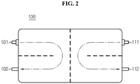
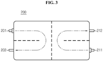
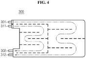
- FIGS. 2 through 5 are cross-sectional views illustrating heat sinks 100, 200, 300, and 400 with cooling channels according to the present disclosure.
- the heat sink according to the present disclosure uses an indirect cooling method to cool a secondary battery.
- heat generated from the secondary battery is transferred to a cooling fin by a contact between the surface of the secondary battery and the cooling fin.
- the cooling fin is connected to a heat sink having a large surface area, and the heat is transferred from the cooling fin to the heat sink.
- the heat sink is cooled by a coolant again.
- the indirect cooling method is a method which cools the secondary battery through the cooling fin and the heat sink, without requiring the coolant to directly pass through the secondary battery.
- the cooling channel formed inside the heat sink should be understood from a cross sectional area of the heat sink.
- the present disclosure features two separated cooling channels.
- the two separated cooling channels have a shorter movement distance than the related art.
- a rate at which the temperature rises with the increasing distance from an inlet of the cooling channel is relatively low. That is, the problem of the related art, i.e., the cooling efficiency reduces with the increasing distance from the inlet of the cooling channel, may be solved.
- inlets 101 and 111 of the two cooling channels are formed at opposing locations with respect to the center of the heat sink 100.
- outlets 102 and 112 of the cooling channels may be also formed at opposing locations with respect to the center of the heat sink 100.
- inlets 201 and 211 of the two cooling channels are formed at diagonal locations with respect to the center of the heat sink 200.
- outlets 202 and 212 of the cooling channels may be also formed at diagonal locations with respect to the center of the heat sink heat sink 200.
- FIGS. 2 and 3 show that a refrigerant flows in the cooling channel only one time for simplification of the drawings, it should be understood that the internal cooling channel may be variously formed.
- the heat sinks 100 and 200 described with reference to FIGS. 2 and 3 are designed such that a heat sink area is divided into halves, a cooling channel is split into halves, and each channel covers half the cooling.
- a channel length is half the channel length of a traditional heat sink, a maximum distance from the inlets 101 and 111 and 201 and 211 of the cooling channels to a point where heat is generated may be reduced by half.
- an inflow of coolant flows in two halves there is an advantage of reducing a loss of pressure in the same system.
- each cooling channel inlet 301 or 311 of the separated channels is formed near the other cooling channel inlet 311 or 301 on the same side of the heat sink 300.
- each cooling channel inlet 401 or 411 of the separated channels is formed near the other cooling channel outlet 412 or 402 on the same side of the heat sink 400.
- FIGS. 2 through 5 present a heat sink with two separated channels as an example, the heat sink according to the present disclosure may have two separated cooling channels as described above. Thus, with the increasing number of separated cooling channels, the number of inlets and outlets of each cooling channel may increase.
- the heat sink according to the present disclosure may be an element of an indirect secondary battery cooling apparatus including the heat sink and a cooling fin in contact with one surface of a secondary battery.
- the indirect secondary battery cooling apparatus may be an element of a battery module including the indirect secondary battery cooling apparatus and at least two secondary batteries.
- the battery module according to the present disclosure may be an element of a battery pack including a plurality of battery modules and a battery management system which controls the charge and discharge of the battery modules.
- the battery pack according to the present disclosure may be an element of a battery operating system including the battery pack and a load which is supplied with power from the battery pack.
- the battery operating system may be, for example, an electric vehicle (EV), a hybrid electric vehicle (HEV), an electric bike, a power tool, an energy storage system, an uninterruptible power supply (UPS), a portable computer, a mobile phone, a portable audio player, or a portable video player, and the load may be a motor that generates a rotational force by power supplied from a battery pack, or a power inverter circuit that inverts power supplied from a battery pack to power required for various circuit components.
- EV electric vehicle
- HEV hybrid electric vehicle
- UPS uninterruptible power supply
- the load may be a motor that generates a rotational force by power supplied from a battery pack, or a power inverter circuit that inverts power supplied from a battery pack to power required for various circuit components.
- the heat sink according to the present disclosure does not limit the scope of the invention by the secondary battery being cooled.
- the secondary battery includes a cell assembly in which at least two unit cells are stacked, each unit cell including a positive electrode plate, a separator, and a negative electrode plate, and a plurality of positive and negative electrode tabs protruding from the positive and negative electrode plates of each unit cell is electrically connected to positive and negative leads, respectively.
- the positive electrode plate is primarily made from aluminum.
- the positive electrode plate may be made from stainless steel, nickel, titanium, baked carbon, or aluminum or stainless steel treated with carbon, nickel, titanium, or silver on the surface.
- the positive electrode plate is not limited to a particular material if it has a high conductivity while not causing a chemical change in the secondary battery.
- the positive electrode tab is provided at a certain area of the positive electrode plate, and may extend from the positive electrode plate.
- the positive electrode tab may be formed by joining a member of a conductive material to a predetermined portion of the positive electrode plate, for example, through welding.
- the positive electrode tab may be formed by coating and drying a positive electrode material on a certain area of a peripheral surface of the positive electrode plate.
- the negative electrode plate corresponding to the positive electrode plate is primarily made from copper.
- the negative electrode plate may be made from stainless steel, aluminum, nickel, titanium, baked carbon, or copper or stainless steel treated with carbon, nickel, titanium, or silver on the surface, and aluminum-cadmium alloys may be also used.
- the negative electrode tab is also provided at a certain area of the negative electrode plate, and similar to the positive electrode tab described above, may extend from the negative electrode plate, and the negative electrode tab may be formed by joining a member of a conductive material to a predetermined portion of the negative electrode plate, for example, through welding, and may be formed by coating and drying a negative electrode material on a certain area of a peripheral surface of the negative electrode plate.
- the positive electrode lead is electrically connected to the positive electrode tab of the positive electrode plate
- the negative electrode lead is electrically connected to the negative electrode tab of the negative electrode plate.
- the positive electrode lead and the negative electrode lead are joined with a plurality of positive electrode tabs and a plurality of negative electrode tabs, respectively.
- the positive electrode plate and the negative electrode plate are coated with a positive electrode active material and a negative electrode active material, respectively.
- the positive electrode active material is a lithium-based active material, and as a typical example, may include metal oxide such as LiCoO 2 , LiNiO 2 , LiMnO 2 , LiMn 2 O 4 , LiFePO 4 , or Li 1+z Ni 1-x-y Co x M y O 2 (0 ⁇ x ⁇ 1, 0 ⁇ y ⁇ 1, 0 ⁇ x+y ⁇ 1, 0 ⁇ z ⁇ 1, M denotes a metal such as Al, Sr, Mg, La, and Mn).
- the negative electrode active material is a carbon-based active material, and may include a carbon material such as crystalline carbon, amorphous carbon, carbon complex, and carbon fibers, lithium metals, and lithium alloys.
- the type and chemical composition of the positive electrode active material and the negative electrode active material may change based on the type of the secondary battery, and it should be understood that the above particular example is just one example.
- the separator is not limited to a particular type, provided it is made from a porous material.
- the separator may be formed of a porous polymer membrane, for example, a porous polyolefin membrane, polyvinylidene fluoride-co-hexafluoropropylene, polyvinylidene fluoride-trichloroethylene, polymethylmetacrylate, polyacrylonitrile, polyvinylpyrrolidone, polyvinylacetate, ethylene vinyl acetate copolymer, polyethyleneoxide, cellulose acetate, cellulose acetate butylate, cellulose acetate propionate, cyanoethylpullulan, cyanoethylpolyvinylalcohol, cyanoethylcellulose, cyanoethylsucrose, pullulan, carboxyl methyl cellulose, acrylonitrile butadiene styrene copolymer, polyimide, polyethylene terephthalate, poly
- the inorganic particles are preferably inorganic particles having a high dielectric constant greater than or equal to 5, and more preferably, inorganic particles having a high dielectric constant greater than or equal to 10 and a low density. This facilitates the transfer of lithium ions moving in the battery.
- Non-limiting examples of inorganic particles having a high dielectric constant greater than or equal to 5 include Pb(Zr,Ti)O 3 (PZT), Pb 1-x La x Zr 1-y Ti y O 3 (PLZT), Pb(Mg 3 Nb 2/3 )O 3 -PbTiO 3 (PMN-PT), BaTiO 3 , hafnia (HfO 2 ), SrTiO 3 , TiO 2 , Al 2 O 3 , ZrO 2 , SnO 2 , CeO 2 , MgO, CaO, ZnO, Y 2 O 3 , or mixtures thereof.
- PZT Pb 1-x La x Zr 1-y Ti y O 3
- PMN-PT Pb(Mg 3 Nb 2/3 )O 3 -PbTiO 3
- BaTiO 3 hafnia
- HfO 2 hafnia
- SrTiO 3 TiO 2 , Al 2 O
- the cell assembly may have a simple stack structure of a plurality of unit cells with an insulating membrane interposed between the unit cells.
- the cell assembly may have a stack folding structure in which unit cells are arranged at an optimum interval on an upper surface and/or a lower surface of an insulating membrane and the insulating membrane is folded in one direction together with the unit cells, so the unit cells are inserted between the folded insulating membrane.
- the cell assembly may have a jelly roll structure formed by mounting, on an insulating membrane, a unit cell extending in the shape of a strand and continuously rolling up the unit cell and the insulating membrane together in one direction.
- the insulating membrane may be made from a material that may be employed as the separator. According to circumstances, the insulating membrane may be made from the same material membrane and/or with the same structure as the separator.
Landscapes
- Engineering & Computer Science (AREA)
- General Chemical & Material Sciences (AREA)
- Manufacturing & Machinery (AREA)
- Chemical & Material Sciences (AREA)
- Chemical Kinetics & Catalysis (AREA)
- Electrochemistry (AREA)
- Power Engineering (AREA)
- Transportation (AREA)
- Mechanical Engineering (AREA)
- Life Sciences & Earth Sciences (AREA)
- Sustainable Development (AREA)
- Sustainable Energy (AREA)
- Microelectronics & Electronic Packaging (AREA)
- Battery Mounting, Suspending (AREA)
- Secondary Cells (AREA)
Description
- The present disclosure relates to a heat sink, and more particularly, to a heat sink with two separated channels.
- The present application claims priority to Korean Patent Application No.
10-2013-0123912 - Due to its characteristics of being easily applicable to various products and electrical properties such as a high energy density, a secondary battery is not only commonly applied to a portable device, but universally applied to an electric vehicle (EV) or a hybrid electric vehicle (HEV) and an energy storage system that is propelled by an electric motor. This secondary battery is gaining attention for its primary advantage of remarkably reducing the use of fossil fuels and not generating by-products from the use of energy, making it a new eco-friendly and energy efficient source of energy.
- A battery pack for use in electric vehicles has a structure consisting of a plurality of cell assemblies connected in series, each cell assembly including a plurality of unit cells, to obtain high power. Also, the unit cell includes a positive electrode current collector and a negative electrode current collector, a separator, an active material, and an electrolyte solution, and allows repeated charging and discharging by electrochemical reactions between the constituent elements.
- Recently, with the growing need for a high-capacity structure as well as utilization as an energy storage source, there is an increase in demand for a battery pack of a multi-module structure in which a plurality of battery modules including a plurality of secondary batteries connected in series and/or in parallel are assembled.
- Because a battery pack of a multi-module structure is designed to have a plurality of secondary batteries arranged with a high density in a narrow space, it is important to easily discharge heat generated from the respective secondary batteries. One of the various methods of discharging heat generated from a secondary battery, a cooling method using a coolant is disclosed in Korean Patent Application Publication No.
10-2013-0062056 -
FIG. 1 is a diagram illustrating the design of acooling channel 10 according to a related art. - Referring to
FIG. 1 , thecooling channel 10 for cooling a secondary battery is illustrated. A refrigerant flowing in thecooling channel 10 enters aninlet 11 and exits anoutlet 12. In thecooling channel 10 of the above structure, the secondary battery is more cooled at theinlet 11 side and is less cooled at theoutlet 12 side. That is, the farther from theinlet 11 and closer to theoutlet 12 the location is, the higher the temperature of the coolant is, so the cooling efficiency reduces. - The above problem of the related art causes a temperature gradient of the secondary battery, and the temperature gradient of the secondary battery leads to a performance gradient of the secondary battery. Finally, it connects with performance deterioration of a system such as a battery pack including the secondary battery. Therefore, there is a need for the design of a cooling channel to provide a uniform cooling effect.
- The present disclosure is designed to address the above issue of the related art, and therefore, the present disclosure is directed to providing a heat sink with two separated channels.
- To achieve the above object, a heat sink according to the present disclosure includes the features as defined in claim 1.
- According to still another embodiment of the present disclosure, each cooling channel inlet of the separated channels may be formed near other cooling channel inlet on a same side of the heat sink.
- According to still another embodiment of the present disclosure, each cooling channel inlet of the separated channels may be formed near other cooling channel outlet on a same side of the heat sink.
- The heat sink according to the present disclosure may be an element of an indirect secondary battery cooling apparatus including the heat sink and a cooling fin which comes into contact with one surface of the secondary battery.
- The indirect secondary battery cooling apparatus according to the present disclosure may be an element of a battery module including the indirect secondary battery cooling apparatus and at least two secondary batteries.
- The battery module according to the present disclosure may be an element of a battery pack including a plurality of battery modules and a battery management system which controls the charge and discharge of the battery modules.
- The battery pack according to the present disclosure may be an element of a battery operating system including the battery pack and a load which is supplied with power from the battery pack. In this instance, the load may be an electrical drive means or a portable device.
- Two separated cooling channels according to the present disclosure have a shorter movement distance than a related art. Thus, as compared to the related art, a rate at which the temperature rises with the increasing distance from an inlet of the cooling channel is relatively low. That is, the problem of the related art, i.e., the cooling efficiency reduces with the increasing distance from the inlet of the cooling channel, may be solved.
- Therefore, provision of a heat sink having a uniform cooling effect is enabled.
- The accompanying drawings illustrate a preferred embodiment of the present disclosure and together with the foregoing disclosure, serve to provide further understanding of the technical spirit of the present disclosure, and thus, the present disclosure is not construed as being limited to the drawings.
-
FIG. 1 is a diagram illustrating the design of a cooling channel according to a related art. -
FIGS. 2 through 5 are cross-sectional views illustrating a heat sink with a cooling channel according to the present disclosure. - Hereinafter, preferred embodiments of the present disclosure will be described in detail with reference to the accompanying drawings. Prior to the description, it should be understood that the terms used in the specification and the appended claims should not be construed as limited to general and dictionary meanings, but interpreted based on the meanings and concepts corresponding to technical aspects of the present disclosure on the basis of the principle that the inventor is allowed to define terms appropriately for the best explanation. Therefore, the description proposed herein is just a preferable example for the purpose of illustrations only, not intended to limit the scope of the disclosure, so it should be understood that other equivalents and modifications could be made thereto without departing from the spirit and scope of the disclosure.
-
FIGS. 2 through 5 are cross-sectional views illustratingheat sinks - The heat sink according to the present disclosure uses an indirect cooling method to cool a secondary battery. According to the indirect cooling method, heat generated from the secondary battery is transferred to a cooling fin by a contact between the surface of the secondary battery and the cooling fin. To dissipate the heat, the cooling fin is connected to a heat sink having a large surface area, and the heat is transferred from the cooling fin to the heat sink. Also, the heat sink is cooled by a coolant again. Thus, the indirect cooling method is a method which cools the secondary battery through the cooling fin and the heat sink, without requiring the coolant to directly pass through the secondary battery. In
FIGS. 2 through 5 , the cooling channel formed inside the heat sink should be understood from a cross sectional area of the heat sink. - Contrary to a related art, the present disclosure features two separated cooling channels. The two separated cooling channels have a shorter movement distance than the related art. Thus, as compared to the related art, a rate at which the temperature rises with the increasing distance from an inlet of the cooling channel is relatively low. That is, the problem of the related art, i.e., the cooling efficiency reduces with the increasing distance from the inlet of the cooling channel, may be solved.
- According to one embodiment of the present disclosure, as shown in
FIG. 2 ,inlets heat sink 100. In this instance,outlets heat sink 100. - According to another embodiment of the present disclosure, as shown in
FIG. 3 ,inlets heat sink 200. In this instance,outlets sink heat sink 200. - Although
FIGS. 2 and3 show that a refrigerant flows in the cooling channel only one time for simplification of the drawings, it should be understood that the internal cooling channel may be variously formed. - The heat sinks 100 and 200 described with reference to
FIGS. 2 and3 are designed such that a heat sink area is divided into halves, a cooling channel is split into halves, and each channel covers half the cooling. As a channel length is half the channel length of a traditional heat sink, a maximum distance from theinlets - According to still another embodiment of the present disclosure, as shown in
FIG. 4 , eachcooling channel inlet 301 or 311 of the separated channels is formed near the othercooling channel inlet 311 or 301 on the same side of theheat sink 300. - According to still another embodiment of the present disclosure, as shown in
FIG. 5 , eachcooling channel inlet cooling channel outlet 412 or 402 on the same side of theheat sink 400. - Although
FIGS. 2 through 5 present a heat sink with two separated channels as an example, the heat sink according to the present disclosure may have two separated cooling channels as described above. Thus, with the increasing number of separated cooling channels, the number of inlets and outlets of each cooling channel may increase. - The heat sink according to the present disclosure may be an element of an indirect secondary battery cooling apparatus including the heat sink and a cooling fin in contact with one surface of a secondary battery.
- The indirect secondary battery cooling apparatus according to the present disclosure may be an element of a battery module including the indirect secondary battery cooling apparatus and at least two secondary batteries.
- The battery module according to the present disclosure may be an element of a battery pack including a plurality of battery modules and a battery management system which controls the charge and discharge of the battery modules.
- The battery pack according to the present disclosure may be an element of a battery operating system including the battery pack and a load which is supplied with power from the battery pack.
- The battery operating system may be, for example, an electric vehicle (EV), a hybrid electric vehicle (HEV), an electric bike, a power tool, an energy storage system, an uninterruptible power supply (UPS), a portable computer, a mobile phone, a portable audio player, or a portable video player, and the load may be a motor that generates a rotational force by power supplied from a battery pack, or a power inverter circuit that inverts power supplied from a battery pack to power required for various circuit components.
- The heat sink according to the present disclosure does not limit the scope of the invention by the secondary battery being cooled. The secondary battery includes a cell assembly in which at least two unit cells are stacked, each unit cell including a positive electrode plate, a separator, and a negative electrode plate, and a plurality of positive and negative electrode tabs protruding from the positive and negative electrode plates of each unit cell is electrically connected to positive and negative leads, respectively.
- The positive electrode plate is primarily made from aluminum. Alternatively, the positive electrode plate may be made from stainless steel, nickel, titanium, baked carbon, or aluminum or stainless steel treated with carbon, nickel, titanium, or silver on the surface. Further, the positive electrode plate is not limited to a particular material if it has a high conductivity while not causing a chemical change in the secondary battery.
- The positive electrode tab is provided at a certain area of the positive electrode plate, and may extend from the positive electrode plate. Alternatively, the positive electrode tab may be formed by joining a member of a conductive material to a predetermined portion of the positive electrode plate, for example, through welding. Also, the positive electrode tab may be formed by coating and drying a positive electrode material on a certain area of a peripheral surface of the positive electrode plate.
- The negative electrode plate corresponding to the positive electrode plate is primarily made from copper. Alternatively, the negative electrode plate may be made from stainless steel, aluminum, nickel, titanium, baked carbon, or copper or stainless steel treated with carbon, nickel, titanium, or silver on the surface, and aluminum-cadmium alloys may be also used.
- The negative electrode tab is also provided at a certain area of the negative electrode plate, and similar to the positive electrode tab described above, may extend from the negative electrode plate, and the negative electrode tab may be formed by joining a member of a conductive material to a predetermined portion of the negative electrode plate, for example, through welding, and may be formed by coating and drying a negative electrode material on a certain area of a peripheral surface of the negative electrode plate.
- The positive electrode lead is electrically connected to the positive electrode tab of the positive electrode plate, and the negative electrode lead is electrically connected to the negative electrode tab of the negative electrode plate. Preferably, the positive electrode lead and the negative electrode lead are joined with a plurality of positive electrode tabs and a plurality of negative electrode tabs, respectively.
- The positive electrode plate and the negative electrode plate are coated with a positive electrode active material and a negative electrode active material, respectively. As an example, the positive electrode active material is a lithium-based active material, and as a typical example, may include metal oxide such as LiCoO2, LiNiO2, LiMnO2, LiMn2O4, LiFePO4, or Li1+zNi1-x-yCoxMyO2 (0≤x≤ 1, 0≤y≤ 1, 0≤x+y≤ 1, 0≤z≤ 1, M denotes a metal such as Al, Sr, Mg, La, and Mn). The negative electrode active material is a carbon-based active material, and may include a carbon material such as crystalline carbon, amorphous carbon, carbon complex, and carbon fibers, lithium metals, and lithium alloys. The type and chemical composition of the positive electrode active material and the negative electrode active material may change based on the type of the secondary battery, and it should be understood that the above particular example is just one example.
- The separator is not limited to a particular type, provided it is made from a porous material. The separator may be formed of a porous polymer membrane, for example, a porous polyolefin membrane, polyvinylidene fluoride-co-hexafluoropropylene, polyvinylidene fluoride-trichloroethylene, polymethylmetacrylate, polyacrylonitrile, polyvinylpyrrolidone, polyvinylacetate, ethylene vinyl acetate copolymer, polyethyleneoxide, cellulose acetate, cellulose acetate butylate, cellulose acetate propionate, cyanoethylpullulan, cyanoethylpolyvinylalcohol, cyanoethylcellulose, cyanoethylsucrose, pullulan, carboxyl methyl cellulose, acrylonitrile butadiene styrene copolymer, polyimide, polyethylene terephthalate, polybutylene terephthalate, polyester, polyacetal, polyamide, polyetheretherketone, polyethersulfone, polyphenylene oxide, polyphenylene sulfidro, polyethylene naphthalene, a non-woven membrane, a membrane having a porous web structure, or combinations thereof. Inorganic particles may be bound to one surface or both surfaces of the separator.
- The inorganic particles are preferably inorganic particles having a high dielectric constant greater than or equal to 5, and more preferably, inorganic particles having a high dielectric constant greater than or equal to 10 and a low density. This facilitates the transfer of lithium ions moving in the battery. Non-limiting examples of inorganic particles having a high dielectric constant greater than or equal to 5 include Pb(Zr,Ti)O3 (PZT), Pb1-xLaxZr1-yTiyO3 (PLZT), Pb(Mg3Nb2/3)O3-PbTiO3(PMN-PT), BaTiO3, hafnia (HfO2), SrTiO3, TiO2, Al2O3, ZrO2, SnO2, CeO2, MgO, CaO, ZnO, Y2O3, or mixtures thereof.
- The cell assembly may have a simple stack structure of a plurality of unit cells with an insulating membrane interposed between the unit cells. As another example, the cell assembly may have a stack folding structure in which unit cells are arranged at an optimum interval on an upper surface and/or a lower surface of an insulating membrane and the insulating membrane is folded in one direction together with the unit cells, so the unit cells are inserted between the folded insulating membrane. As another example, the cell assembly may have a jelly roll structure formed by mounting, on an insulating membrane, a unit cell extending in the shape of a strand and continuously rolling up the unit cell and the insulating membrane together in one direction. The insulating membrane may be made from a material that may be employed as the separator. According to circumstances, the insulating membrane may be made from the same material membrane and/or with the same structure as the separator.
- Hereinabove, the present disclosure has been described by limited embodiments and drawings, but the present disclosure is not limited thereto and it should be understood that various changes and modifications may be made by an ordinary person skilled in the art within the scope of the disclosure and the appended claims and their equivalents.
Claims (6)
- A heat sink (100, 200) comprising:two cooling channels through which a refrigerant suitable for cooling a secondary battery by an indirect cooling method can pass,wherein inlets (101, 111) of the two cooling channels face each other and are formed at opposing sides with respect to the center of the heat sink (100), and outlets (102, 112) of the two cooling channels face each other and are formed at opposing sides with respect to the center of the heat sink (100), orwherein inlets (101, 111) of the two cooling channels are formed at diagonal locations with respect to the center of the heat sink (200), and outlets (102, 112) of the two cooling channels are formed at diagonal locations with respect to the center of the heat sink (200)characterized in thatan area of the heat sink (100, 200) is divided into halves and each of the two cooling channels covers half the cooling.
- An indirect secondary battery cooling apparatus comprising:a heat sink (100, 200) according to claim 1; anda cooling fin suitable for coming into contact with one surface of the secondary battery.
- A battery module comprising:an indirect secondary battery cooling apparatus according to claim 1; andat least two secondary batteries.
- A battery pack comprising:a plurality of battery modules according to claim 3; anda battery management system which controls the charge and discharge of the battery modules.
- A battery operating system comprising:a battery pack according to claim 4; anda load which is supplied with power from the battery pack.
- The battery operating system according to claim 5, wherein the load is an electrical drive means or a portable device.
Priority Applications (1)
| Application Number | Priority Date | Filing Date | Title |
|---|---|---|---|
| PL14853248T PL2933870T3 (en) | 2013-10-17 | 2014-10-07 | Heat sink having two separated flow channels |
Applications Claiming Priority (2)
| Application Number | Priority Date | Filing Date | Title |
|---|---|---|---|
| KR1020130123912A KR101601149B1 (en) | 2013-10-17 | 2013-10-17 | Heat sink having 2 or more separated cooling way |
| PCT/KR2014/009441 WO2015056921A1 (en) | 2013-10-17 | 2014-10-07 | Heat sink having two or more separated flow paths |
Publications (3)
| Publication Number | Publication Date |
|---|---|
| EP2933870A1 EP2933870A1 (en) | 2015-10-21 |
| EP2933870A4 EP2933870A4 (en) | 2016-07-13 |
| EP2933870B1 true EP2933870B1 (en) | 2018-12-05 |
Family
ID=52828311
Family Applications (1)
| Application Number | Title | Priority Date | Filing Date |
|---|---|---|---|
| EP14853248.4A Active EP2933870B1 (en) | 2013-10-17 | 2014-10-07 | Heat sink having two separated flow channels |
Country Status (6)
| Country | Link |
|---|---|
| US (1) | US10637113B2 (en) |
| EP (1) | EP2933870B1 (en) |
| KR (1) | KR101601149B1 (en) |
| CN (1) | CN104919645A (en) |
| PL (1) | PL2933870T3 (en) |
| WO (1) | WO2015056921A1 (en) |
Families Citing this family (7)
| Publication number | Priority date | Publication date | Assignee | Title |
|---|---|---|---|---|
| KR101601142B1 (en) * | 2013-10-18 | 2016-03-08 | 주식회사 엘지화학 | Heat sink having 2 or more separated cooling way with insulation material |
| EP3309858B1 (en) * | 2016-10-13 | 2019-07-10 | Samsung SDI Co., Ltd. | Battery module carrier, battery system and use of a modified h-beam as battery module carrier |
| GB2570300B (en) * | 2018-01-17 | 2020-11-25 | Siemens Ag | Energy storage system |
| KR102204302B1 (en) | 2018-09-13 | 2021-01-15 | 주식회사 엘지화학 | Battery module, battery pack comprising the battery module and vehicle comprising the battery pack |
| US10967756B2 (en) * | 2018-12-20 | 2021-04-06 | National Chung-Shan Institute Of Science And Technology | Liquid cooling module |
| US11799150B2 (en) | 2020-07-17 | 2023-10-24 | Toyota Motor Engineering & Manufacturing North America, Inc. | Cooling structure for hybrid-electric vehicle battery cell assemblies |
| EP4266456A1 (en) * | 2021-02-23 | 2023-10-25 | LG Energy Solution, Ltd. | Battery module and battery pack including same |
Citations (1)
| Publication number | Priority date | Publication date | Assignee | Title |
|---|---|---|---|---|
| US20130189557A1 (en) * | 2010-07-30 | 2013-07-25 | Valeo Klimasysteme Gmbh | Cooling Device For A Vehicle Battery And A Vehicle Battery With Such A Cooling Device |
Family Cites Families (17)
| Publication number | Priority date | Publication date | Assignee | Title |
|---|---|---|---|---|
| JP5147373B2 (en) * | 2007-11-29 | 2013-02-20 | 三洋電機株式会社 | Battery system |
| DE102008027293A1 (en) * | 2008-06-06 | 2009-12-10 | Behr Gmbh & Co. Kg | Device for cooling a vehicle battery |
| DE102008034885A1 (en) * | 2008-07-26 | 2010-01-28 | Daimler Ag | Cooling device for battery for e.g. motor vehicle, has cooling channels formed such that temperature of surface of cooling plate is spatially constant under operating conditions provided for cooling plate |
| US20110244297A1 (en) * | 2009-11-03 | 2011-10-06 | Delphi Technologies, Inc. | Prismatic-cell battery pack with integral coolant channels |
| KR20110090491A (en) | 2010-02-04 | 2011-08-10 | 충북대학교 산학협력단 | Cooling and heating system of large battery for electric vehicle using oscillating heat pipe |
| US8383260B2 (en) * | 2010-02-26 | 2013-02-26 | GM Global Technology Operations LLC | U-formed cooling plate with solid fins for lithium pouch cells |
| DE102010056204A1 (en) * | 2010-03-26 | 2011-09-29 | Daimler Ag | Temperature control element for a battery |
| KR101205181B1 (en) | 2010-05-18 | 2012-11-27 | 주식회사 엘지화학 | Cooling Member of Novel Structure and Battery Module Employed with the Same |
| CH703973A1 (en) | 2010-10-29 | 2012-04-30 | Obrist Engineering Gmbh | Temperature-controlled battery. |
| KR101177887B1 (en) * | 2010-11-22 | 2012-08-29 | 주식회사 한국쿨러 | Battery cell module for electric vehicle using heat sink |
| KR101293971B1 (en) * | 2011-01-26 | 2013-08-07 | 주식회사 엘지화학 | Cooling Member of Improved Cooling Efficiency and Battery Module Employed with the Same |
| JP2012164456A (en) | 2011-02-04 | 2012-08-30 | Kawasaki Heavy Ind Ltd | Heat dissipation plate for secondary battery and method of manufacturing the same, and secondary battery module with heat dissipation plate |
| US8835039B2 (en) * | 2011-10-21 | 2014-09-16 | Avl Powertrain Engineering, Inc. | Battery cooling plate and cooling system |
| DE102011086246A1 (en) * | 2011-11-14 | 2013-05-16 | Sb Limotive Company Ltd. | Battery system and motor vehicle |
| KR101750066B1 (en) | 2011-12-02 | 2017-06-23 | 에스케이이노베이션 주식회사 | Water-cooled type secondary battery |
| KR20130104660A (en) | 2012-03-15 | 2013-09-25 | 에스케이이노베이션 주식회사 | Battery module |
| CN102623771B (en) * | 2012-04-26 | 2017-10-10 | 重庆长安汽车股份有限公司 | A kind of battery cooling plate structure |
-
2013
- 2013-10-17 KR KR1020130123912A patent/KR101601149B1/en active IP Right Grant
-
2014
- 2014-10-07 EP EP14853248.4A patent/EP2933870B1/en active Active
- 2014-10-07 PL PL14853248T patent/PL2933870T3/en unknown
- 2014-10-07 US US14/650,031 patent/US10637113B2/en active Active
- 2014-10-07 CN CN201480005249.XA patent/CN104919645A/en active Pending
- 2014-10-07 WO PCT/KR2014/009441 patent/WO2015056921A1/en active Application Filing
Patent Citations (1)
| Publication number | Priority date | Publication date | Assignee | Title |
|---|---|---|---|---|
| US20130189557A1 (en) * | 2010-07-30 | 2013-07-25 | Valeo Klimasysteme Gmbh | Cooling Device For A Vehicle Battery And A Vehicle Battery With Such A Cooling Device |
Also Published As
| Publication number | Publication date |
|---|---|
| PL2933870T3 (en) | 2019-05-31 |
| US20150318587A1 (en) | 2015-11-05 |
| KR101601149B1 (en) | 2016-03-08 |
| EP2933870A4 (en) | 2016-07-13 |
| CN104919645A (en) | 2015-09-16 |
| KR20150044631A (en) | 2015-04-27 |
| WO2015056921A1 (en) | 2015-04-23 |
| US10637113B2 (en) | 2020-04-28 |
| EP2933870A1 (en) | 2015-10-21 |
Similar Documents
| Publication | Publication Date | Title |
|---|---|---|
| EP2933871B1 (en) | Heat sink having two or more separated channels arranged vertically with common inlet and common outlet | |
| EP2930781B1 (en) | Heat sink with two or more separated channels including insulation material | |
| EP2933870B1 (en) | Heat sink having two separated flow channels | |
| KR101650417B1 (en) | Secondary battery having jelly roll type electrode assembly with intermittent non-coated positive electrode active material | |
| US9692027B2 (en) | Electrode assembly and lithium secondary battery including the same | |
| TW201304248A (en) | Assembled cell | |
| JP2006079987A (en) | Hybrid battery system | |
| US10957955B2 (en) | Battery module and battery pack including the same | |
| US9356294B2 (en) | Secondary battery including collectors with pores and manufacturing method thereof | |
| KR20140111623A (en) | Secondary battery and manufacturing method thereof | |
| KR101760865B1 (en) | Self-cooling method and system using thermoelectric devices for a battery pack | |
| KR20160061122A (en) | Battery pack of improved reaction capability to cell temperature rise and fabricating method for the same | |
| KR20150072107A (en) | Secondary battery peripheral site of the pouch type case is folded through the un-thermal fusion bonding line | |
| KR20150045245A (en) | Heat sink having 2 or more separated cooling way with common gateway | |
| KR101668356B1 (en) | Stack-folding typed electrode assembly and manufacturing methods thereof | |
| US9437898B2 (en) | Secondary battery including plurality of electrode assemblies | |
| EP3353842B1 (en) | Secondary battery |
Legal Events
| Date | Code | Title | Description |
|---|---|---|---|
| PUAI | Public reference made under article 153(3) epc to a published international application that has entered the european phase |
Free format text: ORIGINAL CODE: 0009012 |
|
| 17P | Request for examination filed |
Effective date: 20150715 |
|
| AK | Designated contracting states |
Kind code of ref document: A1 Designated state(s): AL AT BE BG CH CY CZ DE DK EE ES FI FR GB GR HR HU IE IS IT LI LT LU LV MC MK MT NL NO PL PT RO RS SE SI SK SM TR |
|
| AX | Request for extension of the european patent |
Extension state: BA ME |
|
| A4 | Supplementary search report drawn up and despatched |
Effective date: 20160609 |
|
| RIC1 | Information provided on ipc code assigned before grant |
Ipc: H01M 10/65 20140101ALI20160603BHEP Ipc: H01M 2/10 20060101ALI20160603BHEP Ipc: H01M 10/6554 20140101ALI20160603BHEP Ipc: H01M 10/6556 20140101ALI20160603BHEP Ipc: H01M 10/60 20140101AFI20160603BHEP |
|
| DAX | Request for extension of the european patent (deleted) | ||
| STAA | Information on the status of an ep patent application or granted ep patent |
Free format text: STATUS: EXAMINATION IS IN PROGRESS |
|
| 17Q | First examination report despatched |
Effective date: 20170719 |
|
| GRAP | Despatch of communication of intention to grant a patent |
Free format text: ORIGINAL CODE: EPIDOSNIGR1 |
|
| STAA | Information on the status of an ep patent application or granted ep patent |
Free format text: STATUS: GRANT OF PATENT IS INTENDED |
|
| INTG | Intention to grant announced |
Effective date: 20180807 |
|
| GRAS | Grant fee paid |
Free format text: ORIGINAL CODE: EPIDOSNIGR3 |
|
| GRAA | (expected) grant |
Free format text: ORIGINAL CODE: 0009210 |
|
| STAA | Information on the status of an ep patent application or granted ep patent |
Free format text: STATUS: THE PATENT HAS BEEN GRANTED |
|
| AK | Designated contracting states |
Kind code of ref document: B1 Designated state(s): AL AT BE BG CH CY CZ DE DK EE ES FI FR GB GR HR HU IE IS IT LI LT LU LV MC MK MT NL NO PL PT RO RS SE SI SK SM TR |
|
| REG | Reference to a national code |
Ref country code: GB Ref legal event code: FG4D |
|
| REG | Reference to a national code |
Ref country code: CH Ref legal event code: EP |
|
| REG | Reference to a national code |
Ref country code: AT Ref legal event code: REF Ref document number: 1074205 Country of ref document: AT Kind code of ref document: T Effective date: 20181215 |
|
| REG | Reference to a national code |
Ref country code: IE Ref legal event code: FG4D |
|
| REG | Reference to a national code |
Ref country code: DE Ref legal event code: R096 Ref document number: 602014037601 Country of ref document: DE |
|
| REG | Reference to a national code |
Ref country code: NL Ref legal event code: MP Effective date: 20181205 |
|
| REG | Reference to a national code |
Ref country code: AT Ref legal event code: MK05 Ref document number: 1074205 Country of ref document: AT Kind code of ref document: T Effective date: 20181205 |
|
| REG | Reference to a national code |
Ref country code: LT Ref legal event code: MG4D |
|
| PG25 | Lapsed in a contracting state [announced via postgrant information from national office to epo] |
Ref country code: FI Free format text: LAPSE BECAUSE OF FAILURE TO SUBMIT A TRANSLATION OF THE DESCRIPTION OR TO PAY THE FEE WITHIN THE PRESCRIBED TIME-LIMIT Effective date: 20181205 Ref country code: NO Free format text: LAPSE BECAUSE OF FAILURE TO SUBMIT A TRANSLATION OF THE DESCRIPTION OR TO PAY THE FEE WITHIN THE PRESCRIBED TIME-LIMIT Effective date: 20190305 Ref country code: HR Free format text: LAPSE BECAUSE OF FAILURE TO SUBMIT A TRANSLATION OF THE DESCRIPTION OR TO PAY THE FEE WITHIN THE PRESCRIBED TIME-LIMIT Effective date: 20181205 Ref country code: LT Free format text: LAPSE BECAUSE OF FAILURE TO SUBMIT A TRANSLATION OF THE DESCRIPTION OR TO PAY THE FEE WITHIN THE PRESCRIBED TIME-LIMIT Effective date: 20181205 Ref country code: BG Free format text: LAPSE BECAUSE OF FAILURE TO SUBMIT A TRANSLATION OF THE DESCRIPTION OR TO PAY THE FEE WITHIN THE PRESCRIBED TIME-LIMIT Effective date: 20190305 Ref country code: ES Free format text: LAPSE BECAUSE OF FAILURE TO SUBMIT A TRANSLATION OF THE DESCRIPTION OR TO PAY THE FEE WITHIN THE PRESCRIBED TIME-LIMIT Effective date: 20181205 Ref country code: LV Free format text: LAPSE BECAUSE OF FAILURE TO SUBMIT A TRANSLATION OF THE DESCRIPTION OR TO PAY THE FEE WITHIN THE PRESCRIBED TIME-LIMIT Effective date: 20181205 Ref country code: AT Free format text: LAPSE BECAUSE OF FAILURE TO SUBMIT A TRANSLATION OF THE DESCRIPTION OR TO PAY THE FEE WITHIN THE PRESCRIBED TIME-LIMIT Effective date: 20181205 |
|
| PG25 | Lapsed in a contracting state [announced via postgrant information from national office to epo] |
Ref country code: AL Free format text: LAPSE BECAUSE OF FAILURE TO SUBMIT A TRANSLATION OF THE DESCRIPTION OR TO PAY THE FEE WITHIN THE PRESCRIBED TIME-LIMIT Effective date: 20181205 Ref country code: RS Free format text: LAPSE BECAUSE OF FAILURE TO SUBMIT A TRANSLATION OF THE DESCRIPTION OR TO PAY THE FEE WITHIN THE PRESCRIBED TIME-LIMIT Effective date: 20181205 Ref country code: GR Free format text: LAPSE BECAUSE OF FAILURE TO SUBMIT A TRANSLATION OF THE DESCRIPTION OR TO PAY THE FEE WITHIN THE PRESCRIBED TIME-LIMIT Effective date: 20190306 Ref country code: SE Free format text: LAPSE BECAUSE OF FAILURE TO SUBMIT A TRANSLATION OF THE DESCRIPTION OR TO PAY THE FEE WITHIN THE PRESCRIBED TIME-LIMIT Effective date: 20181205 |
|
| PG25 | Lapsed in a contracting state [announced via postgrant information from national office to epo] |
Ref country code: NL Free format text: LAPSE BECAUSE OF FAILURE TO SUBMIT A TRANSLATION OF THE DESCRIPTION OR TO PAY THE FEE WITHIN THE PRESCRIBED TIME-LIMIT Effective date: 20181205 |
|
| PG25 | Lapsed in a contracting state [announced via postgrant information from national office to epo] |
Ref country code: CZ Free format text: LAPSE BECAUSE OF FAILURE TO SUBMIT A TRANSLATION OF THE DESCRIPTION OR TO PAY THE FEE WITHIN THE PRESCRIBED TIME-LIMIT Effective date: 20181205 Ref country code: IT Free format text: LAPSE BECAUSE OF FAILURE TO SUBMIT A TRANSLATION OF THE DESCRIPTION OR TO PAY THE FEE WITHIN THE PRESCRIBED TIME-LIMIT Effective date: 20181205 Ref country code: PT Free format text: LAPSE BECAUSE OF FAILURE TO SUBMIT A TRANSLATION OF THE DESCRIPTION OR TO PAY THE FEE WITHIN THE PRESCRIBED TIME-LIMIT Effective date: 20190405 |
|
| PG25 | Lapsed in a contracting state [announced via postgrant information from national office to epo] |
Ref country code: RO Free format text: LAPSE BECAUSE OF FAILURE TO SUBMIT A TRANSLATION OF THE DESCRIPTION OR TO PAY THE FEE WITHIN THE PRESCRIBED TIME-LIMIT Effective date: 20181205 Ref country code: SK Free format text: LAPSE BECAUSE OF FAILURE TO SUBMIT A TRANSLATION OF THE DESCRIPTION OR TO PAY THE FEE WITHIN THE PRESCRIBED TIME-LIMIT Effective date: 20181205 Ref country code: IS Free format text: LAPSE BECAUSE OF FAILURE TO SUBMIT A TRANSLATION OF THE DESCRIPTION OR TO PAY THE FEE WITHIN THE PRESCRIBED TIME-LIMIT Effective date: 20190405 Ref country code: SM Free format text: LAPSE BECAUSE OF FAILURE TO SUBMIT A TRANSLATION OF THE DESCRIPTION OR TO PAY THE FEE WITHIN THE PRESCRIBED TIME-LIMIT Effective date: 20181205 Ref country code: EE Free format text: LAPSE BECAUSE OF FAILURE TO SUBMIT A TRANSLATION OF THE DESCRIPTION OR TO PAY THE FEE WITHIN THE PRESCRIBED TIME-LIMIT Effective date: 20181205 |
|
| REG | Reference to a national code |
Ref country code: DE Ref legal event code: R097 Ref document number: 602014037601 Country of ref document: DE |
|
| PLBE | No opposition filed within time limit |
Free format text: ORIGINAL CODE: 0009261 |
|
| STAA | Information on the status of an ep patent application or granted ep patent |
Free format text: STATUS: NO OPPOSITION FILED WITHIN TIME LIMIT |
|
| PG25 | Lapsed in a contracting state [announced via postgrant information from national office to epo] |
Ref country code: DK Free format text: LAPSE BECAUSE OF FAILURE TO SUBMIT A TRANSLATION OF THE DESCRIPTION OR TO PAY THE FEE WITHIN THE PRESCRIBED TIME-LIMIT Effective date: 20181205 Ref country code: SI Free format text: LAPSE BECAUSE OF FAILURE TO SUBMIT A TRANSLATION OF THE DESCRIPTION OR TO PAY THE FEE WITHIN THE PRESCRIBED TIME-LIMIT Effective date: 20181205 |
|
| 26N | No opposition filed |
Effective date: 20190906 |
|
| PG25 | Lapsed in a contracting state [announced via postgrant information from national office to epo] |
Ref country code: TR Free format text: LAPSE BECAUSE OF FAILURE TO SUBMIT A TRANSLATION OF THE DESCRIPTION OR TO PAY THE FEE WITHIN THE PRESCRIBED TIME-LIMIT Effective date: 20181205 |
|
| PG25 | Lapsed in a contracting state [announced via postgrant information from national office to epo] |
Ref country code: MC Free format text: LAPSE BECAUSE OF FAILURE TO SUBMIT A TRANSLATION OF THE DESCRIPTION OR TO PAY THE FEE WITHIN THE PRESCRIBED TIME-LIMIT Effective date: 20181205 |
|
| REG | Reference to a national code |
Ref country code: CH Ref legal event code: PL |
|
| PG25 | Lapsed in a contracting state [announced via postgrant information from national office to epo] |
Ref country code: CH Free format text: LAPSE BECAUSE OF NON-PAYMENT OF DUE FEES Effective date: 20191031 Ref country code: LI Free format text: LAPSE BECAUSE OF NON-PAYMENT OF DUE FEES Effective date: 20191031 Ref country code: LU Free format text: LAPSE BECAUSE OF NON-PAYMENT OF DUE FEES Effective date: 20191007 |
|
| REG | Reference to a national code |
Ref country code: BE Ref legal event code: MM Effective date: 20191031 |
|
| PG25 | Lapsed in a contracting state [announced via postgrant information from national office to epo] |
Ref country code: BE Free format text: LAPSE BECAUSE OF NON-PAYMENT OF DUE FEES Effective date: 20191031 |
|
| PG25 | Lapsed in a contracting state [announced via postgrant information from national office to epo] |
Ref country code: IE Free format text: LAPSE BECAUSE OF NON-PAYMENT OF DUE FEES Effective date: 20191007 |
|
| PG25 | Lapsed in a contracting state [announced via postgrant information from national office to epo] |
Ref country code: CY Free format text: LAPSE BECAUSE OF FAILURE TO SUBMIT A TRANSLATION OF THE DESCRIPTION OR TO PAY THE FEE WITHIN THE PRESCRIBED TIME-LIMIT Effective date: 20181205 |
|
| PG25 | Lapsed in a contracting state [announced via postgrant information from national office to epo] |
Ref country code: HU Free format text: LAPSE BECAUSE OF FAILURE TO SUBMIT A TRANSLATION OF THE DESCRIPTION OR TO PAY THE FEE WITHIN THE PRESCRIBED TIME-LIMIT; INVALID AB INITIO Effective date: 20141007 Ref country code: MT Free format text: LAPSE BECAUSE OF FAILURE TO SUBMIT A TRANSLATION OF THE DESCRIPTION OR TO PAY THE FEE WITHIN THE PRESCRIBED TIME-LIMIT Effective date: 20181205 |
|
| PG25 | Lapsed in a contracting state [announced via postgrant information from national office to epo] |
Ref country code: MK Free format text: LAPSE BECAUSE OF FAILURE TO SUBMIT A TRANSLATION OF THE DESCRIPTION OR TO PAY THE FEE WITHIN THE PRESCRIBED TIME-LIMIT Effective date: 20181205 |
|
| P01 | Opt-out of the competence of the unified patent court (upc) registered |
Effective date: 20230512 |
|
| REG | Reference to a national code |
Ref country code: DE Ref legal event code: R081 Ref document number: 602014037601 Country of ref document: DE Owner name: LG ENERGY SOLUTION, LTD., KR Free format text: FORMER OWNER: LG CHEM, LTD., SEOUL, KR |
|
| REG | Reference to a national code |
Ref country code: GB Ref legal event code: 732E Free format text: REGISTERED BETWEEN 20230824 AND 20230831 |
|
| PGFP | Annual fee paid to national office [announced via postgrant information from national office to epo] |
Ref country code: GB Payment date: 20230920 Year of fee payment: 10 |
|
| PGFP | Annual fee paid to national office [announced via postgrant information from national office to epo] |
Ref country code: PL Payment date: 20230921 Year of fee payment: 10 Ref country code: FR Payment date: 20230922 Year of fee payment: 10 |
|
| PGFP | Annual fee paid to national office [announced via postgrant information from national office to epo] |
Ref country code: DE Payment date: 20230920 Year of fee payment: 10 |