JP2012164456A - Heat dissipation plate for secondary battery and method of manufacturing the same, and secondary battery module with heat dissipation plate - Google Patents
Heat dissipation plate for secondary battery and method of manufacturing the same, and secondary battery module with heat dissipation plate Download PDFInfo
- Publication number
- JP2012164456A JP2012164456A JP2011022488A JP2011022488A JP2012164456A JP 2012164456 A JP2012164456 A JP 2012164456A JP 2011022488 A JP2011022488 A JP 2011022488A JP 2011022488 A JP2011022488 A JP 2011022488A JP 2012164456 A JP2012164456 A JP 2012164456A
- Authority
- JP
- Japan
- Prior art keywords
- secondary battery
- flow path
- heat sink
- protrusion
- heat dissipation
- Prior art date
- Legal status (The legal status is an assumption and is not a legal conclusion. Google has not performed a legal analysis and makes no representation as to the accuracy of the status listed.)
- Withdrawn
Links
Images


Classifications
-
- Y—GENERAL TAGGING OF NEW TECHNOLOGICAL DEVELOPMENTS; GENERAL TAGGING OF CROSS-SECTIONAL TECHNOLOGIES SPANNING OVER SEVERAL SECTIONS OF THE IPC; TECHNICAL SUBJECTS COVERED BY FORMER USPC CROSS-REFERENCE ART COLLECTIONS [XRACs] AND DIGESTS
- Y02—TECHNOLOGIES OR APPLICATIONS FOR MITIGATION OR ADAPTATION AGAINST CLIMATE CHANGE
- Y02E—REDUCTION OF GREENHOUSE GAS [GHG] EMISSIONS, RELATED TO ENERGY GENERATION, TRANSMISSION OR DISTRIBUTION
- Y02E60/00—Enabling technologies; Technologies with a potential or indirect contribution to GHG emissions mitigation
- Y02E60/10—Energy storage using batteries
Abstract
Description
本発明は、二次電池用の放熱板およびその製造方法、ならびに放熱板を用いた二次電池モジュールに関し、特に単位電池を複数積層してなる二次電池モジュールに用いる放熱板およびその製造方法に関する。 The present invention relates to a heat radiating plate for a secondary battery, a method for manufacturing the same, and a secondary battery module using the heat radiating plate, and more particularly to a heat radiating plate used for a secondary battery module in which a plurality of unit cells are stacked and a method for manufacturing the same. .
単位電池を複数積層してなる二次電池モジュールは、従来、種々提案されている。この種の二次電池モジュールは、電気製品からハイブリッド車,鉄道車両,マイクログリッドシステムに至るまで様々に用いられている。特に、ハイブリッド車や鉄道車両,マイクログリッドシステムにおいては、二次電池モジュールに高出力,大容量のものが要求される。そのため、このような二次電池モジュールには、エネルギー密度の高いニッケル水素電池やリチウムイオン電池などが用いられている。 Various secondary battery modules in which a plurality of unit batteries are stacked have been proposed. This type of secondary battery module is used in various applications ranging from electrical products to hybrid vehicles, railway vehicles, and microgrid systems. In particular, in a hybrid vehicle, a railway vehicle, and a microgrid system, a high output and large capacity secondary battery module is required. For this reason, nickel hydride batteries and lithium ion batteries with high energy density are used for such secondary battery modules.
一方、これらニッケル水素電池やリチウムイオン電池は大電流を流すため、電池が発熱し高温となる場合がある。電池が高温となると、充放電効率が下がったり、電池寿命が短くなることがある。特に、鉄道車両やマイクログリッドシステムなどに用いる場合、電池が大型となるため、このような大型の二次電池モジュールには、電池を冷却するための冷却構造を採用したものが提案されている。 On the other hand, since these nickel hydride batteries and lithium ion batteries pass a large current, the batteries may generate heat and become high temperature. When the battery becomes high temperature, the charge / discharge efficiency may decrease or the battery life may be shortened. In particular, when used in a railway vehicle, a microgrid system, or the like, since the battery becomes large, such a large secondary battery module has been proposed that employs a cooling structure for cooling the battery.
この種の先行技術として、上下方向に貫通する通風孔(流通経路)を複数設け、導電材として、表面をニッケルメッキした電池の放熱用仕切り板(放熱板)を用いた冷却構造が提案されている(例えば、特許文献1参照)。 As this type of prior art, a cooling structure using a plurality of ventilation holes (distribution paths) penetrating in the vertical direction and using a heat dissipation partition plate (heat dissipation plate) of a battery whose surface is nickel-plated as a conductive material has been proposed. (For example, refer to Patent Document 1).
また、その他の先行技術として、二次電池とは異なる燃料電池の分野において、燃料電池の電池スタックに配置する冷却板であって、その内部に冷却ガスを流通する冷却通路を設け、該冷却通路に通路長に亘る小突起を所定間隔に配列した燃料電池用の冷却板が提案されている(例えば、特許文献2参照)。 As another prior art, in the field of a fuel cell different from a secondary battery, a cooling plate disposed in a cell stack of the fuel cell, in which a cooling passage for circulating a cooling gas is provided, and the cooling passage A cooling plate for a fuel cell has been proposed in which small protrusions extending along the passage length are arranged at predetermined intervals (see, for example, Patent Document 2).
特許文献1に記載の放熱用仕切り板は、その内部に設けた通風孔内に空気を通過させ熱交換により電池を冷却するものである。しかしながら、この放熱用仕切り板においては、通風孔の入口から流入した空気のうち内壁付近の空気は、通風孔内を進むにつれて熱交換され温度が高くなる一方、中心付近の空気は比較的温度が低いままである。つまり、通風孔内の中心付近を通過する空気は、放熱板との熱交換があまり行われないままに通風孔内を通過することとなるため、冷却媒体としての空気が十分に利用されていないという課題があった。
The heat radiating partition plate described in
特許文献2に記載の燃料電池用の冷却板は、冷却ガスが冷却通路内に設けられた小突起に衝突することにより小渦流を発生させ、冷却ガスが通路内壁面と繰り返し衝突することによって熱伝達率を増大し、冷却効果を向上させるものである。しかしながら、燃料電池における通路の高さは一般に数百μmと非常に小さいため、小突起による擾乱効果はほとんど期待できないという課題があった。
The cooling plate for a fuel cell described in
以上のように、電池冷却が十分でないと二次電池が高温となり、二次電池の充放電効率の低下や、電池寿命の低下を招く。また一方で、二次電池を強制的に冷却するために冷却ファンを大容量化する方法も用いられるが、電力消費量が大きくなり電池の効率の低下を招く。 As described above, if the battery is not sufficiently cooled, the secondary battery becomes high temperature, leading to a decrease in charge / discharge efficiency of the secondary battery and a decrease in battery life. On the other hand, in order to forcibly cool the secondary battery, a method of increasing the capacity of the cooling fan is also used, but the power consumption increases and the efficiency of the battery is reduced.
本発明は、かかる従来の問題点に鑑みてなされたものであって、簡単な構造で電池の効率が良く、かつ、冷却効率の高い二次電池用の放熱板およびその製造方法、ならびに該放熱板を備えた二次電池モジュールを提供するものである。 The present invention has been made in view of the above-described conventional problems, and has a simple structure, good battery efficiency, and high cooling efficiency for a secondary battery, its manufacturing method, and the heat dissipation. A secondary battery module provided with a plate is provided.
上記の課題を解決するために本発明にかかる二次電池用の放熱板は、単位電池を複数積層してなる二次電池モジュールの、前記単位電池の間に配する放熱板であって、
前記単位電池の積層方向に直交し、冷却媒体が流通する冷却媒体流路を備え、前記冷却媒体流路内に突起が設けられている。
In order to solve the above problems, a heat sink for a secondary battery according to the present invention is a heat sink disposed between the unit batteries of a secondary battery module in which a plurality of unit batteries are stacked,
A cooling medium flow path that is orthogonal to the stacking direction of the unit cells and through which the cooling medium flows is provided, and a protrusion is provided in the cooling medium flow path.
この構成によれば、流路内に流入した冷却媒体が突起に衝突することによって、流路内壁面付近の高温の冷却媒体と流路中心付近の低温の冷却媒体との温度境界層が引きはがされ、これらが混ざり合うことにより、冷却媒体の温度を略均一にできる。つまり、流路中心付近の低温の冷却媒体を有効に活用して、流路内壁面付近の冷却媒体の温度を低下させられる。 According to this configuration, the cooling medium that has flowed into the flow path collides with the protrusions, so that the temperature boundary layer between the high temperature cooling medium near the flow path inner wall surface and the low temperature cooling medium near the flow path center is pulled. By mixing these, the temperature of the cooling medium can be made substantially uniform. That is, the temperature of the cooling medium near the inner wall surface of the flow path can be lowered by effectively using the low-temperature cooling medium near the center of the flow path.
ここで、突起の形状は、冷却媒体の進行方向に直交する形状や傾斜した形状、逆方向に傾斜した形状など種々の形状が考えられるが、好ましくは進行方向に傾斜した形状である。このようにすれば、流路抵抗を小さくでき、冷却媒体の流速低下を抑え、冷却効率の低下を抑制できる。 Here, the shape of the protrusion may be various shapes such as a shape orthogonal to the traveling direction of the cooling medium, an inclined shape, or a shape inclined in the opposite direction, but is preferably a shape inclined in the traveling direction. In this way, the flow resistance can be reduced, a decrease in the flow rate of the cooling medium can be suppressed, and a decrease in cooling efficiency can be suppressed.
突起の高さは、たとえば流路高さの1/4〜3/4といったように、ある程度の高さがあることが好ましい。このようにすれば、流路内壁付近の冷却媒体と流路中心付近の冷却媒体とがよく混合され、冷却媒体の温度の均一化に都合がよい。 It is preferable that the height of the protrusion has a certain height, for example, ¼ to ¾ of the channel height. In this way, the cooling medium near the inner wall of the flow path and the cooling medium near the center of the flow path are well mixed, which is convenient for making the temperature of the cooling medium uniform.
さらに、突起の高さを流路高さの1/3〜2/3、より好適には突起の形状によるが、略1/2とすれば、冷却媒体の温度の均一化と流路抵抗の抑制とをバランスよく達成しうる。 Furthermore, if the height of the protrusion is 1/3 to 2/3 of the height of the flow path, and more preferably depends on the shape of the protrusion, if the height is approximately 1/2, the temperature of the cooling medium is made uniform and the flow resistance is reduced. Suppression can be achieved in a balanced manner.
なお、冷却媒体には、例えば空気などの気体や、シリコン油、電気絶縁油、PCB油などの液体を用いる。 As the cooling medium, for example, a gas such as air or a liquid such as silicon oil, electrical insulating oil, or PCB oil is used.
また、積層する単位電池が、積層方向における単位電池の前後面がそれぞれ正極板・負極板で構成されている場合、この放熱板を導電性とすることで各単位電池を電気的に接続することが容易にできる。つまり、この放熱板が、隣り合う単位電池の対向する正極板と負極板とに当接することにより、これら単位電池を電気的に接続可能となる。 In addition, when the unit cells to be stacked are configured so that the front and rear surfaces of the unit cells in the stacking direction are each made of a positive electrode plate and a negative electrode plate, each unit cell is electrically connected by making the heat dissipation plate conductive. Can be easily done. In other words, the unit batteries can be electrically connected by contacting the positive and negative electrode plates of the adjacent unit batteries facing each other.
請求項2にかかる二次電池用の放熱板は、前記突起が前記放熱板の外面からの切り起こしにより形成されている。
In the heat dissipation plate for a secondary battery according to
この構成によれば、放熱板の流路に容易に突起を設けることができる。ここで、切り起こしとは、例えば二辺の刃を持つ三角刃を放熱板の外面からプレスすることで、一片を残し他の二辺を切断しつつ内側に折り込み、三角形状の突起を流路側に立ち上げることをいう。なお、突起の形状は刃の形状を変えることで、矩形状や台形状、円形状、楕円形状など種々の変更が可能である。また、十字の切込みを作り、流路側に起こしてもよい。さらには、流路に突起のない既存の放熱板に、後加工による切り起こしによって突起を設けることも可能である。 According to this configuration, the protrusion can be easily provided in the flow path of the heat sink. Here, cutting and raising means, for example, pressing a triangular blade having two-sided blades from the outer surface of the heat sink, folding the other two sides inward while leaving one piece, and forming triangular projections on the channel side To start up. The shape of the protrusion can be variously changed by changing the shape of the blade, such as a rectangular shape, a trapezoidal shape, a circular shape, or an elliptical shape. Also, a cross cut may be made and raised on the channel side. Furthermore, it is also possible to provide protrusions by cutting and raising by post-processing on an existing heat sink having no protrusions in the flow path.
なお、切り起こし以外に、放熱板を外部から凹ませて流路内に突起を作ることもできる。この方法においても、既存の放熱板に突起を設けることが可能である。 In addition to cutting and raising, the heat sink can be recessed from the outside to make a protrusion in the flow path. Also in this method, it is possible to provide a protrusion on an existing heat sink.
請求項3にかかる二次電池用の放熱板は、前記流路の入口部から前記突起までの距離が、前記流路における等価水力直径の10倍以上である。 In the heat radiating plate for a secondary battery according to a third aspect, the distance from the inlet of the flow path to the protrusion is 10 times or more the equivalent hydraulic diameter in the flow path.
この構成によれば、冷却媒体は、一般的に流路入口部に乱流の状態で流入するため、入口付近では既に流れが乱れているので突起によって、温度を均一化するという効果があまり期待できない。冷却媒体が流路内をある程度進行した段階、つまり流路内で冷却媒体の流れの乱れが減少し、流路内壁付近と流路中心付近との冷却媒体の温度差があらわれる位置以降に突起を設けることが望ましい。ここで、等価水力直径とは、流路断面と等価な円管の直径をいい、4*流路断面積/断面長により求められる代表長さである。この等価水力直径の略10倍以上においては、流路内の冷却媒体の流れに乱れがなく、熱伝達率はほぼ一定となる(図12参照)。 According to this configuration, since the cooling medium generally flows into the flow path inlet in a turbulent state, the flow is already turbulent near the inlet, so the effect of equalizing the temperature by the protrusions is not much expected. Can not. Projections are made after the stage where the cooling medium has progressed to some extent in the flow path, that is, where the turbulence of the flow of the cooling medium in the flow path is reduced and the temperature difference between the cooling medium temperature near the flow path inner wall and the flow path center appears. It is desirable to provide it. Here, the equivalent hydraulic diameter means a diameter of a circular pipe equivalent to the cross section of the flow path, and is a representative length obtained by 4 * flow path cross sectional area / cross section length. When the equivalent hydraulic diameter is approximately 10 times or more, the flow of the cooling medium in the flow path is not disturbed, and the heat transfer coefficient is substantially constant (see FIG. 12).
請求項4にかかる二次電池用の放熱板は、前記放熱板に複数の前記流路が平行に配され、前記各流路内に前記突起を複数設け、前記各流路内における各突起間のスパンが、等価水力直径の10倍以上である。
The heat sink for a secondary battery according to
この構成によれば、放熱板に複数の流路を配することで電池全体を略均一に冷却することができる。また、各流路内に複数の突起を設けることで、より効果的に電池を冷却することができる。 According to this structure, the whole battery can be cooled substantially uniformly by arranging a plurality of flow paths in the heat sink. Further, by providing a plurality of protrusions in each flow path, the battery can be cooled more effectively.
請求項5にかかる二次電池用の放熱板は、前記流路の断面が、一方が開口した溝型形状である。
The heat sink for a secondary battery according to
この構成によれば、放熱板を単位電池に配すると、流路が単位電池と放熱板により形成されることとなり、冷却媒体が直接単位電池に接触するため、冷却効率が高い。 According to this configuration, when the heat radiating plate is arranged in the unit battery, the flow path is formed by the unit battery and the heat radiating plate, and the cooling medium directly contacts the unit battery, so that the cooling efficiency is high.
請求項6にかかる二次電池モジュールは、単位電池を複数積層し、前記単位電池の間に放熱板を配した電池モジュールであって、前記放熱板が、請求項1〜6のいずれか1項に記載の放熱板である。 The secondary battery module according to claim 6 is a battery module in which a plurality of unit cells are stacked and a heat dissipation plate is arranged between the unit cells, and the heat dissipation plate is any one of claims 1-6. It is a heat sink as described in.
この構成によれば、前記した各種放熱板を単位電池間に配することで、冷却性能の高い二次電池モジュールを提供することができる。 According to this structure, a secondary battery module with high cooling performance can be provided by arranging the various heat sinks described above between unit cells.
請求項7にかかる二次電池モジュールは、前記単位電池がニッケル水素二次電池である。 In the secondary battery module according to claim 7, the unit battery is a nickel-hydrogen secondary battery.
この構成によれば、単位電池毎のエネルギー密度が高く、高出力の二次電池モジュールを提供することができる。 According to this configuration, it is possible to provide a secondary battery module having a high energy density for each unit battery and a high output.
請求項8にかかる放熱板の製造方法は、単位電池を複数積層してなる二次電池モジュールの、前記単位電池の間に配する放熱板の製造方法であって、
前記単位電池の積層方向に直交し、冷却媒体が流通する流路を備えた前記放熱板を押出成形により形成する第1の工程と、前記放熱板の外面からプレス加工によって、前記流路内に切り起こしによる突起を形成する第2の工程と、前記放熱板にメッキ加工を施す第3の工程とを備える。
The manufacturing method of the heat sink concerning Claim 8 is a manufacturing method of the heat sink arranged between the unit batteries of the secondary battery module formed by laminating a plurality of unit batteries,
A first step of forming the heat radiating plate, which is orthogonal to the stacking direction of the unit cells, and provided with a flow path through which a cooling medium flows, by extrusion molding, and pressing the outer surface of the heat radiating plate into the flow path. A second step of forming protrusions by cutting and raising, and a third step of plating the heat radiating plate.
この構成によれば、放熱板を押出成形し、切り起こしによる突起を形成した後にメッキ加工を施すことで、メッキ後に加工した場合のメッキの剥がれを予防できる。また、メッキ後にプレス加工する場合に比べメッキ前にプレス加工すると、素材が柔らかくプレスが容易でプレス型も長持ちする。 According to this configuration, by extruding the heat radiating plate and forming the protrusions by cutting and raising, the plating process is performed, so that peeling of the plating when processed after the plating can be prevented. In addition, when pressing before plating, the material is soft and easy to press, and the press die lasts longer than when pressing after plating.
さらに、流路内に突起のない既存の放熱板に、後加工による切り起こしによって突起を設けることも可能である。 Furthermore, it is also possible to provide a protrusion by cutting and raising by post-processing on an existing heat sink having no protrusion in the flow path.
以上のように、本発明にかかる二次電池用の放熱板は、簡単な構造で、二次電池を効率よく冷却できる。また、本発明にかかる二次電池用の放熱板の製造方法は、冷却効率を向上した放熱板を容易に製造でき作業性がよい。さらに、本発明にかかる二次電池モジュールは、従来のものと寸法を変えずに、冷却性能を向上できる。 As described above, the heat sink for a secondary battery according to the present invention has a simple structure and can efficiently cool the secondary battery. Moreover, the manufacturing method of the heat sink for secondary batteries concerning this invention can manufacture the heat sink which improved cooling efficiency easily, and its workability | operativity is good. Furthermore, the secondary battery module according to the present invention can improve the cooling performance without changing the size from the conventional one.
以下、本発明の実施形態にかかる二次電池用の放熱板およびその製造方法、該放熱板を配した二次電池モジュールについて、図面に基づき説明するが、本発明は下記実施形態に限定されるものではない。なお、図1〜図9中の矢印は空気の流れる方向を示し、図10中の矢印は熱の伝達する方向を示す。 Hereinafter, although the heat sink for secondary batteries concerning the embodiment of the present invention, its manufacturing method, and the secondary battery module which arranged this heat sink are explained based on a drawing, the present invention is limited to the following embodiment. It is not a thing. 1 to 9 indicate the direction of air flow, and the arrow in FIG. 10 indicates the direction of heat transfer.
1.[放熱板1の構成]
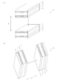
図1,図2に示すように、本実施形態にかかる放熱板1は、外形が矩形板状であって、その内部に長手方向に沿って伸びる複数の中空部11と、三角形板状の突起12とを備える。中空部11は、冷却媒体としての空気が流通する流路として用いる。なお、放熱板1は、たとえば、アルミニウム材,ニッケルメッキを施したアルミニウム材,ニッケル材など,導電性を有する材料からなる。また、中空部11は本実施形態において放熱板1の長手方向(図1のY方向)に設けているが、中空部の配置は長手方向に限定されるものではなく、たとえば長手方向に直交する方向(図1のX方向)に設けてもよい。
1. [Configuration of heat sink 1]
As shown in FIGS. 1 and 2, the
突起12は、各中空部11(以下、流路11という)の長手方向中央部に1つずつ配する。図2(c)のように、突起12をすべて各流路11の中央部に設けてもよいし、図2(d)のように、突起12を流路11毎にそれぞれ別の位置に設けてもよい。突起12は、放熱板1の上面から三角刃をプレスして形成する。具体的には、図3(a),(b)に示すように、三角刃によって2辺を切断し、残りの1辺を中心に流路11側に折り曲げて切り起こす。なお、図3(c)のように、放熱板1の上面から流路11側に凹ませて突起12’を形成してもよい。
One
また、突起12は、空気の流通方向(図1,図2の矢印方向)に傾斜させ、三角形の頂点部分が流路11の高さの略1/2、つまり突起12の高さが流路11の高さの略1/2となるように切り起こす。これにより、流路内の空気を十分に混合できると同時に、突起を垂直に立てた場合に比べ流路抵抗を抑え圧力損失を抑制できる。
The
空気が流路11に流入すると、流路11を進むにつれて、流路内壁付近の空気は電池との熱交換により温度が上昇する。そして、空気が突起12に達した時に、流路内壁付近の高温の空気と流路中心付近の低温の空気とが混合され、空気の温度は均一化し流路内壁付近の温度よりも低くなる。その均一化し低温となった空気が流路11を通過するため、従来よりも効率よく単位電池2を冷却できる。
When air flows into the flow path 11, the temperature of the air near the inner wall of the flow path rises due to heat exchange with the battery as it travels through the flow path 11. When the air reaches the
次に、放熱板1の変形例について説明する。
(変形例1)
上記実施形態の放熱板は、各流路11の長手方向中央部に1つの突起12を設けたものであるが、突起12は各流路11に複数あってもよい。図4に示すように、(a)は各流路11に3個の突起12を均等に配したものである。(b)は2個の突起12を均等に配し、(c)は2個の突起12を入口部寄りに、(d)は2個の突起12を出口部寄りに配したものである。突起12を複数設けることで、最初の突起12で混合された空気が、再び流路内壁付近で電池との熱交換により温度が上昇した後、次の突起12で再度空気を混合し温度を均一化できる。これにより、電池の冷却効率をさらに向上できる。
Next, a modified example of the
(Modification 1)
Although the heat sink of the said embodiment provided the one
(変形例2)
また、図5に示すように、突起12の配置は、一方向(例えば、流路11上面側や流路11下面側)の配置に限定されず、3個の突起12を流路11の上面側、下面側、上面側と順に配置してもよい。さらに、図5(d)に示すように、隣の流路と交互に上面側、下面側と配置してもよい。
(Modification 2)
Further, as shown in FIG. 5, the arrangement of the
(変形例3)
また、突起12の形状は三角形状に限定されるものではない。例えば、図6に示すように、矩形状や台形状、円形状、半円形状、楕円形状等でもよく、十字の切込みを入れ流路側に起こして形成してもよい。要は、流路内11の空気を効率よく混合でき、流路抵抗が小さく圧力損失を抑えたものであればよい。
(Modification 3)
Further, the shape of the
(変形例4)
また、図7(a),(b)に示すように、放熱板1の形状を変更して各流路11の断面形状を同一方向(上面側)に開口した溝型の形状としてもよいし、交互(上面側と下面側)に開口した形状としてもよい。このようにすれば、図7(c),(d)にしめすように、放熱板1を単位電池2の間に配した時に、流路11が単位電池2と放熱板1とにより形成されることとなる。そのため、空気が流路11を通過する際、空気が直接単位電池2に接触するため、冷却効率がより高くなる。
(Modification 4)
Further, as shown in FIGS. 7A and 7B, the shape of the
2.[放熱板1の製造方法]
放熱板1の製造方法は、まずアルミの押出成形により、放熱板1の外形を形成する。次に、放熱板1の上面側から各流路11の中央部付近で三角刃をプレス加工して、切り起こしにより突起12を形成する。最後に、突起12が形成された放熱板1をニッケルメッキする。
2. [Method of manufacturing heat sink 1]
The manufacturing method of the
上記工程のように、放熱板1を押出成形した後に突起12をプレス加工することで、突起12を容易に成形することができる。また、最後にニッケルメッキを行うことで、メッキ後にプレス加工する場合に比べ、メッキ前にプレス加工すると素材が柔らかく、プレスが容易でプレス型も長持ちする。さらに、メッキ後に突起12を加工した場合のメッキの剥がれも予防できる。
Like the said process, the
3.[二次電池モジュールの構成]
本発明の二次電池モジュールは、単位電池2と放熱板1とを交互に積層し、両端に集電体を配置してなる。また、図8に示すように、積層方向は上下方向Xに積層してもよいし(図8(a))、前後方向Yに積層してもよい(図8(b))。なお、本実施形態では、30個の単位電池2を放熱板1と交互に積層したものであるが、放熱板1を単位電池2の2つおきに配置するなど種々の変更が可能である。
3. [Configuration of secondary battery module]
The secondary battery module of the present invention is formed by alternately stacking
単位電池2は、密閉型のニッケル水素電池である。図10に示すように単位電池2は、積層方向Xの上下に、導電性の良い金属からなる正極集電体21と負極集電体23とが対向して設けられている。これら正極集電体21と負極集電体23との間には、イオンは透過するが電子を透過しない蛇腹状のセパレータ25が交互に両集電体に近接するように配置され、これにより正極部と負極部とに区画されている。そして、セパレータ25と正極集電体21とで形成される各空間には電解質溶液とともに正極活物質を含有する正極シート22が配置され、セパレータ25と負極集電体23とで形成される区画される空間には電解質溶液とともに負極活物質を含有する負極シート24が配置され、正極シート22と負極シート24とがセパレータ25を挟んで交互に組み込まれている。なお、正極集電体21と負極集電体23は、それぞれ正極シート22及び負極シート24と接触し、それぞれ正極,負極を構成する。したがって、各単位電池2を、正極集電体21と負極集電体23とが対向するように積層することで、各単位電池2を電気的に接続することができるし、各単位電池2間に導電性の放熱板1を介してもよい。
The
なお、本実施形態において、正極シート22は、例えば、正極活物質と導電性フィラー(導電材)と樹脂とに溶剤を加えてペースト状にしたものを基板上に塗布して板状に成形し、硬化させたものである。負極シート24は、例えば、負極活物質と導電性フィラーと樹脂とに溶剤を加えてペースト状にしたものを基板上に塗布して板状に成形し、硬化させたものである。
In this embodiment, for example, the positive electrode sheet 22 is formed into a plate by applying a paste to a positive electrode active material, a conductive filler (conductive material), and a resin by adding a solvent. , Cured. The
正極活物質および負極活物質としては、すべての公知の活物質材料を用いることができる。導電性フィラーとしては、炭素繊維、炭素繊維にニッケルメッキしたもの、炭素粒子、炭素粒子にニッケルメッキしたもの、有機繊維にニッケルメッキしたもの、繊維状ニッケル、ニッケル粒子、ニッケル箔などを単独または組み合わせて用いることができる。樹脂としては、軟化温度120℃までの熱可塑性樹脂、硬化温度が常温から120℃までの熱硬化性樹脂、蒸発温度120℃以下の溶剤に溶解する樹脂、水に可溶な溶剤に溶解する樹脂、アルコールに可溶な溶剤に溶解する樹脂などを用いることができる。基板としては、アルミ板、ニッケルメッキを施したアルミ板、ニッケル板などの導電性のある金属板などを用いることができる。 As the positive electrode active material and the negative electrode active material, all known active material materials can be used. As the conductive filler, carbon fiber, carbon fiber nickel-plated, carbon particles, carbon particle nickel-plated, organic fiber nickel-plated, fibrous nickel, nickel particles, nickel foil, etc. alone or in combination Can be used. Examples of the resin include a thermoplastic resin having a softening temperature of 120 ° C., a thermosetting resin having a curing temperature from room temperature to 120 ° C., a resin that dissolves in a solvent having an evaporation temperature of 120 ° C. or less, and a resin that dissolves in a water-soluble solvent. Resins that are soluble in alcohol-soluble solvents can be used. As the substrate, a conductive metal plate such as an aluminum plate, a nickel-plated aluminum plate, or a nickel plate can be used.
(1)冷却構造
次に、本実施形態1に係る冷却構造について説明する。図9に示すように、冷却媒体としての空気が、流路11を図9中の矢印の方向へ流通し、単位電池2を冷却する。この時、空気が放熱板1を冷却して、冷却された放熱板1が当接する単位電池2を表面から冷却する。なお、単位電位2は図10に示す構成をとるため、電池反応の結果、単位電池2の正極シート24又は負極シート22に発生した熱は、図10に示す矢印の方向に伝達されて、正極集電体21や負極集電体23で冷媒たる空気に触れ、外部に放出されるので、効率的に単位電池2を冷却することができる。このように単位電池2を冷却することで、単位電池2の温度を、電池反応がスムーズに実行できる適正な範囲に維持することができる。
(1) Cooling Structure Next, the cooling structure according to the first embodiment will be described. As shown in FIG. 9, air as a cooling medium flows through the flow path 11 in the direction of the arrow in FIG. 9 to cool the
(2)吸気ファンを備えた二次電池
更に冷却効率を向上させるための構造例を図11に示す。図11は、強制冷却を行う吸気ファン4と風洞(空気流通空間)51,52とを備えた冷却ユニット5の構成を示した斜視図である。冷却ユニット5の内部に二次電池モジュールを配置することで、吸気ファン4によって下部空気流通空間51に吸い込まれた空気が、放熱板1の流路11を通過し、上部空気流通空間52を経て外部に放出される。なお、図11において、矢印は空気の流れる方向を示す。強制冷却することで、冷却効率を高めることができる。
(2) Secondary Battery with Intake Fan FIG. 11 shows a structural example for further improving the cooling efficiency. FIG. 11 is a perspective view showing the configuration of the
以上のとおり、図面を参照しながら本発明の好適な実施形態を説明したが、本発明の趣旨を逸脱しない範囲内で、種々の追加、変更または削除が可能である。特に、突起12の個数や配置、形状などを変更してもよく、また、流路11の断面形状も矩形状以外に円形状や楕円形状としてもよい。したがって、そのようなものも本発明の範囲内に含まれる。
As described above, the preferred embodiments of the present invention have been described with reference to the drawings, but various additions, modifications, or deletions can be made without departing from the spirit of the present invention. In particular, the number, arrangement, and shape of the
1 放熱板
11 流路(中空部)
12,12’ 突起
2 単位電池
21 正極集電体
22 正極シート
23 負極集電体
24 負極シート
25 セパレータ
3 集電板
4 吸気ファン
5 冷却ユニット
51 上部空気流通空間
52 下部空気流通空間
A,B 二次電池モジュール
1 Heat sink 11 Channel (hollow part)
12, 12 '
Claims (8)
前記単位電池の積層方向に直交し、冷却媒体が流通する流路を備え、
前記流路内に突起が設けられている二次電池用の放熱板。 A secondary battery module formed by laminating a plurality of unit batteries, a secondary battery heat sink disposed between the unit batteries,
A flow path perpendicular to the stacking direction of the unit cells and through which a cooling medium flows,
A heat dissipation plate for a secondary battery, wherein a protrusion is provided in the flow path.
前記各流路内に前記突起を複数設け、
前記各流路内における各突起間のスパンが、等価水力直径の10倍以上である二次電池用の放熱板。 In any one of Claims 1-3, the said several flow path is arrange | positioned in parallel by the said heat sink,
A plurality of the protrusions are provided in each flow path,
A heat dissipation plate for a secondary battery, wherein a span between the protrusions in each flow path is 10 times or more the equivalent hydraulic diameter.
前記放熱板が、請求項1〜5のいずれか1項に記載の放熱板である二次電池モジュール。 A battery module in which a plurality of unit cells are stacked and a heat sink is disposed between the unit cells,
The secondary battery module whose said heat sink is a heat sink of any one of Claims 1-5.
前記単位電池の積層方向に直交し、冷却媒体が流通する流路を備えた前記放熱板を押出成形により形成する第1の工程と、
前記放熱板の外面からプレス加工によって、前記流路内に切り起こしによる突起を形成する第2の工程と、
前記放熱板にメッキ加工を施す第3の工程とを備える二次電池用の放熱板の製造方法。 A method of manufacturing a heat sink for a secondary battery disposed between the unit batteries of a secondary battery module formed by laminating a plurality of unit batteries,
A first step of forming the heat radiating plate orthogonal to the stacking direction of the unit cells and having a flow path through which a cooling medium flows by extrusion;
A second step of forming protrusions by cutting and raising in the flow path by pressing from the outer surface of the heat sink;
A method for manufacturing a heat sink for a secondary battery, comprising: a third step of plating the heat sink.
Priority Applications (1)
| Application Number | Priority Date | Filing Date | Title |
|---|---|---|---|
| JP2011022488A JP2012164456A (en) | 2011-02-04 | 2011-02-04 | Heat dissipation plate for secondary battery and method of manufacturing the same, and secondary battery module with heat dissipation plate |
Applications Claiming Priority (1)
| Application Number | Priority Date | Filing Date | Title |
|---|---|---|---|
| JP2011022488A JP2012164456A (en) | 2011-02-04 | 2011-02-04 | Heat dissipation plate for secondary battery and method of manufacturing the same, and secondary battery module with heat dissipation plate |
Publications (1)
| Publication Number | Publication Date |
|---|---|
| JP2012164456A true JP2012164456A (en) | 2012-08-30 |
Family
ID=46843677
Family Applications (1)
| Application Number | Title | Priority Date | Filing Date |
|---|---|---|---|
| JP2011022488A Withdrawn JP2012164456A (en) | 2011-02-04 | 2011-02-04 | Heat dissipation plate for secondary battery and method of manufacturing the same, and secondary battery module with heat dissipation plate |
Country Status (1)
| Country | Link |
|---|---|
| JP (1) | JP2012164456A (en) |
Cited By (14)
| Publication number | Priority date | Publication date | Assignee | Title |
|---|---|---|---|---|
| WO2014162980A1 (en) * | 2013-04-02 | 2014-10-09 | カルソニックカンセイ株式会社 | Temperature adjustment device for storage battery |
| JP2015118799A (en) * | 2013-12-18 | 2015-06-25 | 古河電池株式会社 | Storage battery housing box |
| CN104835991A (en) * | 2014-02-12 | 2015-08-12 | 马勒贝洱有限两合公司 | Cooling device, in particular for battery of motor vehicle |
| CN108063049A (en) * | 2018-01-12 | 2018-05-22 | 无锡巨日电子科技有限公司 | The high efficiency and heat radiation of center heat transfer and the energy type super capacitor of heating |
| WO2018101751A1 (en) * | 2016-11-29 | 2018-06-07 | 주식회사 엘지화학 | Air-cooling type battery module |
| WO2018155755A1 (en) * | 2017-02-24 | 2018-08-30 | 엠에이치기술개발(주) | Battery cooling apparatus and manufacturing method therefor |
| CN109454849A (en) * | 2018-12-20 | 2019-03-12 | 武汉励志机电设备有限公司 | A kind of hollow grid plate water cooling mold plate |
| CN109860952A (en) * | 2019-03-13 | 2019-06-07 | 郑州工业应用技术学院 | A kind of adjustable radiator structure of new energy car battery |
| WO2019163689A1 (en) * | 2018-02-22 | 2019-08-29 | パナソニックIpマネジメント株式会社 | Cooling device for secondary battery, and vehicle |
| JP2019530191A (en) * | 2016-08-30 | 2019-10-17 | ビーワイディー カンパニー リミテッド | Battery module, battery pack for traveling, and automobile |
| US10637113B2 (en) | 2013-10-17 | 2020-04-28 | Lg Chem, Ltd. | Heat sink with two or more separated channels |
| CN112531260A (en) * | 2019-09-03 | 2021-03-19 | 本田技研工业株式会社 | Accumulator battery |
| CN116207363A (en) * | 2023-04-28 | 2023-06-02 | 南昌航空大学 | Preparation method and structure of battery cell |
| WO2023098322A1 (en) * | 2021-11-30 | 2023-06-08 | 宁德时代新能源科技股份有限公司 | Thermal management component, battery and electric device |
-
2011
- 2011-02-04 JP JP2011022488A patent/JP2012164456A/en not_active Withdrawn
Cited By (20)
| Publication number | Priority date | Publication date | Assignee | Title |
|---|---|---|---|---|
| JP2014203563A (en) * | 2013-04-02 | 2014-10-27 | カルソニックカンセイ株式会社 | Temperature adjustment device for storage battery |
| WO2014162980A1 (en) * | 2013-04-02 | 2014-10-09 | カルソニックカンセイ株式会社 | Temperature adjustment device for storage battery |
| US10637113B2 (en) | 2013-10-17 | 2020-04-28 | Lg Chem, Ltd. | Heat sink with two or more separated channels |
| JP2015118799A (en) * | 2013-12-18 | 2015-06-25 | 古河電池株式会社 | Storage battery housing box |
| CN104835991A (en) * | 2014-02-12 | 2015-08-12 | 马勒贝洱有限两合公司 | Cooling device, in particular for battery of motor vehicle |
| CN104835991B (en) * | 2014-02-12 | 2019-04-19 | 马勒贝洱有限两合公司 | Particularly for the cooling equipment of the battery group of motor vehicles |
| JP2019530191A (en) * | 2016-08-30 | 2019-10-17 | ビーワイディー カンパニー リミテッド | Battery module, battery pack for traveling, and automobile |
| WO2018101751A1 (en) * | 2016-11-29 | 2018-06-07 | 주식회사 엘지화학 | Air-cooling type battery module |
| US10892529B2 (en) | 2016-11-29 | 2021-01-12 | Lg Chem, Ltd. | Air-cooling battery module |
| WO2018155755A1 (en) * | 2017-02-24 | 2018-08-30 | 엠에이치기술개발(주) | Battery cooling apparatus and manufacturing method therefor |
| CN108063049A (en) * | 2018-01-12 | 2018-05-22 | 无锡巨日电子科技有限公司 | The high efficiency and heat radiation of center heat transfer and the energy type super capacitor of heating |
| CN108063049B (en) * | 2018-01-12 | 2023-07-21 | 无锡巨日电子科技有限公司 | Energy-type super capacitor with efficient heat dissipation and heating of central heat transfer |
| WO2019163689A1 (en) * | 2018-02-22 | 2019-08-29 | パナソニックIpマネジメント株式会社 | Cooling device for secondary battery, and vehicle |
| CN109454849A (en) * | 2018-12-20 | 2019-03-12 | 武汉励志机电设备有限公司 | A kind of hollow grid plate water cooling mold plate |
| CN109454849B (en) * | 2018-12-20 | 2024-03-15 | 武汉励志机电设备有限公司 | Novel water-cooling shaping plate of cavity grid plate |
| CN109860952A (en) * | 2019-03-13 | 2019-06-07 | 郑州工业应用技术学院 | A kind of adjustable radiator structure of new energy car battery |
| CN109860952B (en) * | 2019-03-13 | 2021-04-16 | 郑州工业应用技术学院 | Adjustable heat radiation structure for new energy automobile battery |
| CN112531260A (en) * | 2019-09-03 | 2021-03-19 | 本田技研工业株式会社 | Accumulator battery |
| WO2023098322A1 (en) * | 2021-11-30 | 2023-06-08 | 宁德时代新能源科技股份有限公司 | Thermal management component, battery and electric device |
| CN116207363A (en) * | 2023-04-28 | 2023-06-02 | 南昌航空大学 | Preparation method and structure of battery cell |
Similar Documents
| Publication | Publication Date | Title |
|---|---|---|
| JP2012164456A (en) | Heat dissipation plate for secondary battery and method of manufacturing the same, and secondary battery module with heat dissipation plate | |
| US9159973B2 (en) | Battery module and power supply apparatus | |
| US9520624B2 (en) | Battery module with compact structure and excellent heat radiation characteristics and middle or large-sized battery pack employed with the same | |
| JP6255016B2 (en) | Energy storage device and method of making energy storage device | |
| KR101233318B1 (en) | Battery module | |
| EP2523249B1 (en) | Mid- or large-sized battery pack having improved cooling efficiency | |
| US8298699B2 (en) | Power storage device | |
| US8435668B2 (en) | Prismatic battery cell with integrated cooling passages and assembly frame | |
| JP5535520B2 (en) | Battery system for vehicle | |
| JP2013526766A (en) | Cooling member having compact structure and excellent stability, and battery module having the same | |
| TW201737549A (en) | Heat sink and battery module including the same | |
| WO2019001466A1 (en) | Cylindrical lithium ion battery | |
| JP2012104225A (en) | Battery module, method of manufacturing battery module and spacer for battery | |
| CN200969366Y (en) | Accumulator battery for mixed motor vehicle of wind cooling forced radiating structure | |
| EP3764454B1 (en) | Battery module | |
| JP2011253734A (en) | Battery pack and vehicle | |
| JP2019114444A (en) | Assembled battery spacer and assembled battery | |
| CN210110999U (en) | Power battery heat radiation structure | |
| EP3648238A1 (en) | Lithium ion power battery | |
| CN106340697B (en) | Binary channels group battery air cooling structure | |
| EP3648241A1 (en) | Thermally conductive lithium ion battery | |
| KR101074493B1 (en) | PEMFC having a pin type flow channel | |
| KR20200067588A (en) | Battery module and method of manufacturing the same | |
| CN220358139U (en) | Air-cooled fuel cell stack and bipolar plate thereof | |
| CN218827457U (en) | Battery liquid cooling device |
Legal Events
| Date | Code | Title | Description |
|---|---|---|---|
| A300 | Withdrawal of application because of no request for examination |
Free format text: JAPANESE INTERMEDIATE CODE: A300 Effective date: 20140513 |