EP2933864A1 - Stapelstruktur für eine brennstoffzelle - Google Patents
Stapelstruktur für eine brennstoffzelle Download PDFInfo
- Publication number
- EP2933864A1 EP2933864A1 EP13862876.3A EP13862876A EP2933864A1 EP 2933864 A1 EP2933864 A1 EP 2933864A1 EP 13862876 A EP13862876 A EP 13862876A EP 2933864 A1 EP2933864 A1 EP 2933864A1
- Authority
- EP
- European Patent Office
- Prior art keywords
- fuel
- fuel cell
- stack structure
- convex
- cell stack
- Prior art date
- Legal status (The legal status is an assumption and is not a legal conclusion. Google has not performed a legal analysis and makes no representation as to the accuracy of the status listed.)
- Granted
Links
Images

Classifications
-
- H—ELECTRICITY
- H01—ELECTRIC ELEMENTS
- H01M—PROCESSES OR MEANS, e.g. BATTERIES, FOR THE DIRECT CONVERSION OF CHEMICAL ENERGY INTO ELECTRICAL ENERGY
- H01M8/00—Fuel cells; Manufacture thereof
- H01M8/02—Details
- H01M8/0202—Collectors; Separators, e.g. bipolar separators; Interconnectors
- H01M8/0247—Collectors; Separators, e.g. bipolar separators; Interconnectors characterised by the form
- H01M8/0254—Collectors; Separators, e.g. bipolar separators; Interconnectors characterised by the form corrugated or undulated
-
- H—ELECTRICITY
- H01—ELECTRIC ELEMENTS
- H01M—PROCESSES OR MEANS, e.g. BATTERIES, FOR THE DIRECT CONVERSION OF CHEMICAL ENERGY INTO ELECTRICAL ENERGY
- H01M8/00—Fuel cells; Manufacture thereof
- H01M8/04—Auxiliary arrangements, e.g. for control of pressure or for circulation of fluids
-
- H—ELECTRICITY
- H01—ELECTRIC ELEMENTS
- H01M—PROCESSES OR MEANS, e.g. BATTERIES, FOR THE DIRECT CONVERSION OF CHEMICAL ENERGY INTO ELECTRICAL ENERGY
- H01M8/00—Fuel cells; Manufacture thereof
- H01M8/02—Details
- H01M8/0271—Sealing or supporting means around electrodes, matrices or membranes
-
- H—ELECTRICITY
- H01—ELECTRIC ELEMENTS
- H01M—PROCESSES OR MEANS, e.g. BATTERIES, FOR THE DIRECT CONVERSION OF CHEMICAL ENERGY INTO ELECTRICAL ENERGY
- H01M8/00—Fuel cells; Manufacture thereof
- H01M8/04—Auxiliary arrangements, e.g. for control of pressure or for circulation of fluids
- H01M8/04082—Arrangements for control of reactant parameters, e.g. pressure or concentration
- H01M8/04089—Arrangements for control of reactant parameters, e.g. pressure or concentration of gaseous reactants
-
- H—ELECTRICITY
- H01—ELECTRIC ELEMENTS
- H01M—PROCESSES OR MEANS, e.g. BATTERIES, FOR THE DIRECT CONVERSION OF CHEMICAL ENERGY INTO ELECTRICAL ENERGY
- H01M8/00—Fuel cells; Manufacture thereof
- H01M8/24—Grouping of fuel cells, e.g. stacking of fuel cells
-
- H—ELECTRICITY
- H01—ELECTRIC ELEMENTS
- H01M—PROCESSES OR MEANS, e.g. BATTERIES, FOR THE DIRECT CONVERSION OF CHEMICAL ENERGY INTO ELECTRICAL ENERGY
- H01M8/00—Fuel cells; Manufacture thereof
- H01M8/24—Grouping of fuel cells, e.g. stacking of fuel cells
- H01M8/241—Grouping of fuel cells, e.g. stacking of fuel cells with solid or matrix-supported electrolytes
- H01M8/2425—High-temperature cells with solid electrolytes
- H01M8/2432—Grouping of unit cells of planar configuration
-
- H—ELECTRICITY
- H01—ELECTRIC ELEMENTS
- H01M—PROCESSES OR MEANS, e.g. BATTERIES, FOR THE DIRECT CONVERSION OF CHEMICAL ENERGY INTO ELECTRICAL ENERGY
- H01M8/00—Fuel cells; Manufacture thereof
- H01M8/24—Grouping of fuel cells, e.g. stacking of fuel cells
- H01M8/2457—Grouping of fuel cells, e.g. stacking of fuel cells with both reactants being gaseous or vaporised
-
- H—ELECTRICITY
- H01—ELECTRIC ELEMENTS
- H01M—PROCESSES OR MEANS, e.g. BATTERIES, FOR THE DIRECT CONVERSION OF CHEMICAL ENERGY INTO ELECTRICAL ENERGY
- H01M8/00—Fuel cells; Manufacture thereof
- H01M8/24—Grouping of fuel cells, e.g. stacking of fuel cells
- H01M8/2465—Details of groupings of fuel cells
- H01M8/2483—Details of groupings of fuel cells characterised by internal manifolds
-
- H—ELECTRICITY
- H01—ELECTRIC ELEMENTS
- H01M—PROCESSES OR MEANS, e.g. BATTERIES, FOR THE DIRECT CONVERSION OF CHEMICAL ENERGY INTO ELECTRICAL ENERGY
- H01M8/00—Fuel cells; Manufacture thereof
- H01M8/24—Grouping of fuel cells, e.g. stacking of fuel cells
- H01M8/249—Grouping of fuel cells, e.g. stacking of fuel cells comprising two or more groupings of fuel cells, e.g. modular assemblies
-
- H—ELECTRICITY
- H01—ELECTRIC ELEMENTS
- H01M—PROCESSES OR MEANS, e.g. BATTERIES, FOR THE DIRECT CONVERSION OF CHEMICAL ENERGY INTO ELECTRICAL ENERGY
- H01M2300/00—Electrolytes
- H01M2300/0017—Non-aqueous electrolytes
- H01M2300/0065—Solid electrolytes
- H01M2300/0068—Solid electrolytes inorganic
- H01M2300/0071—Oxides
- H01M2300/0074—Ion conductive at high temperature
-
- Y—GENERAL TAGGING OF NEW TECHNOLOGICAL DEVELOPMENTS; GENERAL TAGGING OF CROSS-SECTIONAL TECHNOLOGIES SPANNING OVER SEVERAL SECTIONS OF THE IPC; TECHNICAL SUBJECTS COVERED BY FORMER USPC CROSS-REFERENCE ART COLLECTIONS [XRACs] AND DIGESTS
- Y02—TECHNOLOGIES OR APPLICATIONS FOR MITIGATION OR ADAPTATION AGAINST CLIMATE CHANGE
- Y02E—REDUCTION OF GREENHOUSE GAS [GHG] EMISSIONS, RELATED TO ENERGY GENERATION, TRANSMISSION OR DISTRIBUTION
- Y02E60/00—Enabling technologies; Technologies with a potential or indirect contribution to GHG emissions mitigation
- Y02E60/30—Hydrogen technology
- Y02E60/50—Fuel cells
Definitions
- the present invention relates to a fuel cell stack structure, and more particularly, to a fuel cell stack structure in which at least one defective fuel cell among a plurality of stacked fuel cells to increase the amount of electric power is capable of being easily replaced.
- a fuel cell is a generator which includes a cathode layer and an anode layer on respective surfaces of an electrolyte layer, and generates electricity by an electrochemical reaction between hydrogen and oxygen through ion conduction occurring at the electrolyte layer when an air including oxygen and a fuel gas including hydrogen are supplied to the cathode layer and the anode layer, respectively.
- Such a fuel cell is a highly efficient and pollution-free generator having a simple energy conversion process and, in principle, generates energy through oxidation of hydrogen. Because of such an environmentally friendly characteristic, recently, studies of fuel cells have been actively progressing.
- a solid oxide fuel cell is a fuel cell operated at a high temperature of approximately 600 to 1000 °C using a ceramic as an electrolyte, and has various advantages such as the highest efficiency among the various types of fuel cells including a molten carbonate fuel cell (MCFC), a phosphoric acid fuel cell (PAFC), a polymer electrolyte fuel cell (PEFC), etc., less pollution, and enabling combined cycle power generation without a fuel processor.
- MCFC molten carbonate fuel cell
- PAFC phosphoric acid fuel cell
- PEFC polymer electrolyte fuel cell
- a fuel cell having a structure of an electrolyte layer, a cathode layer and an anode layer is usually called a single cell. Since electricity generated by the single cell is approximately less than 1 V, which is ineffective, a technique of increasing a generated voltage by stacking a plurality of single cells in the form of a stack structure has received attention.
- first and second separation plates electrically connected to each other are disposed between the single cells to only change a single defective cell when defects are found in the single cells.
- an air hole and a fuel hole are disposed to provide an air and a fuel gas to the cathode layer and the anode layer, and a sealing member is disposed to seal the holes.
- the first and second separation plates have an unstable electrical contact due to a height of the sealing member, or fine unevenness by a processing error, which is caused by a difficulty in processing the plates to a perfect plane, and have an oxidized contact surface in a space formed by the unstable contact, thereby increasing an electrical resistance between the first and second separation plates.
- SOFCs solid oxide fuel cells
- their operating temperature are very high, for example, approximately 600 to 1000 °C, and thus the contact surface may be more easily formed, thereby further increasing the electrical resistance.
- the electrical resistance is increased as described above, collection efficiency of electricity generated from the single cells may be degraded.
- the present invention is directed to providing a fuel cell stack structure, which has a stable electrical contact between first and second separation plates disposed to separate fuel cells into one or more in number.
- the present invention provides a fuel cell stack structure, which includes first and second cell modules and first and second separation plates.
- each of the first and second cell modules at least one fuel cell which includes an electrolyte layer, and a cathode layer and an anode layer formed on both surfaces of the electrolyte layer, and generates electricity, is stacked.
- the first and second separation plates are electrically connected to each other at a part in which the first and second cell modules face each other, and at least one separation plate has a protruded convex to improve an electrical contact with the other.
- Each of the first and second separation plates according to the exemplary embodiment has an air hole and a fuel hole in edges to provide an air including oxygen and a fuel gas including hydrogen to the cathode layer and the anode layer, and at least one separation plate has a sealing unit for sealing the air hole and the fuel hole.
- the convex may have a protruded structure on a different part from the sealing unit.
- the sealing unit according to the exemplary embodiment may have a partially-open structure to provide the fuel gas provided from the fuel hole to the convex.
- a fluid space may be formed between the convex according to the exemplary embodiment and the sealing unit to flow the fuel gas provided from the fuel hole.
- a channel through the fuel gas provided from the fuel hole may be formed in the convex or a part of the first and second separation plates facing the convex.
- a height of the convex according to an exemplary embodiment may be the same as or smaller than that of the sealing unit.
- the sealing unit according to an exemplary embodiment may include a ceramic material.
- a conductive film coated with a contact paste having a conductive material may be formed on the convex according to an exemplary embodiment.
- the conductive material may include a non-precious metal material.
- At least one of the first and second separation plates may include a first flat plate and a second flat plate in contact with the first flat plate and forming the convex structure.
- a conductive film coated with a contact paste having a conductive material may be formed on at least one surface of the second flat plate according to an exemplary embodiment.
- the second flat plate may have a structure joined to the first flat plate by welding.
- first and second may be used to explain various components, but the components should not be limited to the terms. The terms are only used to discriminate one component from another component. For example, without departing from the scope of the present invention, a first component may be referred to as a second component, and similarly, a second component may also be referred to as a first component.
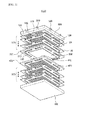
- FIG. 1 is an exploded perspective view of a fuel cell stack structure according to an exemplary embodiment of the present invention
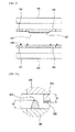
- FIG. 2 is a cross-sectional view of first and second separation plates of the fuel cell stack structure shown in FIG. 1 .
- a fuel cell stack structure 1000 includes first and second cell modules 100 and 200 and first and second separation plates 300 and 400.
- the first and second cell modules 100 and 200 include one or more stacked fuel cells 110, respectively, and are disposed to face each other.
- the fuel cell 110 includes an electrolyte layer (not shown), and a cathode layer (not shown) and an anode layer (not shown) respectively disposed on both surfaces of the electrolyte layer, and generates electricity.
- the fuel cell 110 generates electricity by an electrochemical reaction between hydrogen and oxygen through ion conduction in the electrolyte layer when an air including oxygen and a fuel gas including hydrogen flow to the cathode layer and the anode layer, respectively.
- the electrolyte layer may be formed of a ceramic material having high ion conductivity, excellent stability in an excellent redox atmosphere and an excellent mechanical property.
- the electrolyte layer may be formed of yttriastabilized zirconia (YSZ), (La, Sr)(Ga, Mg)O 3 , Ba(Zr,Y)O 3 , Gd doped CeO 2 (GDC), Y 2 O 3 doped CeO 2 (YDC), etc.
- the fuel cell 110 including such an electrolyte layer is usually referred to as a solid oxide fuel cell (SOFC), and operated at a high temperature of approximately 600 to 1000 °C.
- the cathode layer may be formed in a porous structure using lanthanum strontium manganite (LSM) or lanthanum strontium cobalt ferrite (LSCF) for oxygen migration.
- LSM lanthanum strontium manganite
- LSCF lanthanum strontium cobalt ferrite
- the lanthanum strontium manganite is a composite of lanthanum (La), strontium (Sr) and manganese (Mn)
- lanthanum strontium cobalt ferrite is a composite of lanthanum (La), strontium (Sr), cobalt (Co) and iron (Fe).
- the anode layer may be formed in a porous structure using a mixture of yttriastabilized zirconia (YSZ) and nickel (Ni) for hydrogen migration.
- each of the first and second cell modules 100 and 200 includes an interconnector 120 disposed between adjacent ones of the stacked fuel cells 110 to electrically connect the fuel cells in series to obtain a high voltage therefrom.
- the interconnector 120 is electrically connected with the cathode layer of one of the adjacent fuel cells 110 and the anode layer of the other of the adjacent fuel cell 110.
- the interconnector 120 may be in contact with the cathode layer of one of the adjacent fuel cells 110 and the anode layer of the other of the adjacent fuel cell 110.
- the interconnector 120 may have channel forming units 124 serving as partitions to form a plurality of channels 122 through which the air or fuel gas uniformly flows.
- the channel forming units 124 may be formed on both of the top and bottom surfaces of the interconnector 120.
- first air holes 126 through which the air is provided and exhausted are formed in first and second sides of the interconnector 120, respectively, which are disposed opposite to each other, and first fuel holes 128 through which the fuel gas is provided and exhausted are formed in third and fourth sides of the interconnector 120, respectively, which are disposed opposite to each other.
- first and second sides may be disposed along a first direction and the third and fourth sides may be disposed along a second direction substantially perpendicular to the first direction.
- the first and second separation plates 300 and 400 are disposed between the first and second cell modules 100 and 200 facing each other.
- the first and second cell modules 100 and 200 may be electrically connected by the first and second separation plates 300 and 400, and may be separably combined to each other by the first and second separation plates 300 and 400.
- the first and second separation plates 300 and 400 may be separated from each other. Therefore, when the fuel cell 100 included in any one of the first and second cell modules 100 and 200 has a defect, the module having the defective fuel cell may be separated and changed.
- electricity generated from the first and second cell modules 100 and 200 may be collected together.
- the first separation plate 300 is disposed between the first cell module 100 and the second cell module 200 to face the bottom of the first cell module 100. Therefore, the first separation plate 300 has a structure in which a top surface is electrically connected with the fuel cell 110, and the bottom surface is exposed to an external environment.
- the top surface of the first separation plate 300 may have the same structure as the top or bottom surface of the interconnector 120 to flow the air or fuel gas to the cathode layer or anode layer of the fuel cell 110.
- the interconnector 120 may be further disposed between the top surface of the first separation plate 300 and the fuel cell 110 to electrically connect the top surface of the first separation plate 300 with the fuel cell 110.
- the first separation plate 300 may be formed of an stainless steel material such as SUS material to have a heat resistance to the fuel cell 110 operated at a high temperature of approximately 600 to 1000 °C and have electrical conductivity.
- a coating film (not shown) may be formed on the first separation plate 300.
- the coating film may be formed of lanthanum strontium manganite (LSM) or lanthanum strontium cobalt ferrite (LSCF).
- the coating film may be formed of a mixed material including at least one selected from manganese (Mn), cobalt (Co), copper (Cu), iron (Fe), nickel (Ni), zinc (Zn), tin (Sn) and titanium (Ti).
- Mn manganese
- Co cobalt
- Cu copper
- Fe iron
- Ni nickel
- Zn zinc
- Ti titanium
- the interconnector 120 since the interconnector 120 may also be in the same environment as the first separation plate 300, it may be formed of the same material as the first separation plate 300.
- first separation plate 300 may include second air holes 310 and second fuel holes 320 communicating with the first air holes 126 and the first fuel holes 128, respectively, to provide the air and the fuel gas to the cathode layer and the anode layer of the fuel cell 110 included in the first cell module 100.
- the second separation plate 400 is disposed between the first separation plate 300 and the second cell module 200 to face the top of the second cell module 200. Accordingly, a top surface of the second separation plate 400 is connected with the exposed bottom surface of the first separation plate 300, and a bottom surface of the second separation plate 400 is electrically connected with the fuel cell 110.
- a structure of the second separation plate 400 may be the same as that of the first separation plate 300, but reversed.
- the second separation plate 400 is electrically connected in series through area contact with the first separation plate 300 for collecting electricity generated from the first and second cell modules 100 and 200.
- the second separation plate 400 may also be formed of the same material as the first separation plate 300 to have a resistance to a high temperature and have electrical conductivity.
- the second separation plate 400 may include third air holes 410 and third fuel holes 420 communicating with the second air holes 310 and the second fuel holes 320, respectively, to provide the air and the fuel gas to the cathode layer and anode layer of the fuel cell 110 included in the second cell module 200.
- sealing units 430 may be disposed on the second separation plate 400, when in area contact with the first separation plate 300, to seal around the second and third air holes 310 and 410 and the second and third fuel holes 320 and 420.
- the sealing units 430 may be formed on edges of the first and second separation plates 300 and 400 due to locations at which the second and third air holes 310 and 410 and the second and third fuel holes 320 and 420 communicate with the first air holes 126 and the first fuel holes 128.
- the first separation plate 300 includes a convex 330 protruded to the second separation plate 400.
- the convex 330 may prevent break of the surface contact of the first separation plate 300 and the second separation plate 400 caused by the sealing unit 430 disposed therebetween.
- the convex 330 may be formed at a center portion of the first separation plate 300.
- sealing unit 430 is disposed between the first separation plate 300 and the second separation plate 400, a structure in which the first and second separation plates 300 and 400 are in surface contact with each other due to the convex 330 of the first separation plate 300 will also be described in further detail with additional reference to FIGS. 3A and 3B .
- FIGS. 3A and 3B are views specifically illustrating a state in which the first and second separation plates shown in FIG. 2 are connected to each other.
- a height H1 of the convex 330 of the first separation plate 300 may be substantially the same as or smaller by a predetermined value than that of the sealing unit 430 of the second separation plate 400.
- the centers of the first and second separation plates 300 and 400 may have an electrical and stable area contact with each other due to the convex 330 even when the sealing unit 430 having a predetermined height H2 is disposed between edge portions of the separation plates 300 and 400, or fine unevenness or a processing error during processing is generated. Accordingly, since the convex 330 may reduce an electrical contact resistance between the separation plates 300 and 400 by the convex 330, electricity generated from the first and second cell modules 100 and 200 may be more efficiently collected.
- the amount of electric power collected from the first and second cell modules 100 and 200 is approximately 900 W, but when the convex 330 is formed on the first separation plate 300 as described in the present invention, an amount of collected electric power is approximately 950 W, and it is confirmed that the collection efficiency is improved by approximately 5.3%.
- the sealing unit 430 of the second separation plate 400 may be formed of a ceramic material having a slightly lower elasticity but excellent heat resistance to be stably resistant to a high temperature of approximately 600 to 1000 °C at which the fuel cell 110 is operated.
- the sealing unit 430 may be formed of a mica material or felt.
- a glass sealer having excellent sealability may be used, and in this case, due to the property of the glass, the glass may flow. To suppress this, the flowability may be controlled by adding a fiber.
- the sealing unit 430 may be formed of any material which can be resistant to a high temperature at which the fuel cell 110 is operated, even though having lower or no elasticity, due to the convex 330 of the first separation plate 300.
- a conductive film 332 coated with a contact paste having a conductive material on a surface facing the second separation plate 400 may be formed on the convex 330 of the first separation plate 300. Therefore, even though the surface of the convex 330 is partially uneven, the conductive film 332 may be evenly formed due to predetermined flowability of the contact paste material, thereby providing a more stable electrical contact between the first and second separation plates 300 and 400.
- the convex 330 is formed on the first separation plate 300, and the sealing unit 430 is disposed on the second separation plate 400.
- the convex 330 may be formed on the second separation plate 400
- the sealing unit 430 may be disposed on the first separation plate 300, or both of the convex 330 and the sealing unit 430 may be formed or disposed on any one of the first and second separation plates 300 and 400.
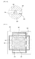
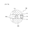
- FIG. 4 illustrates a state in which a fuel gas flows between the first and second separation plates shown in FIG. 2 according to an exemplary embodiment.
- the sealing unit 430 disposed on the second separation plate 400 may have openings 432 to provide the fuel gas including hydrogen provided from at least one of the third fuel holes 420 to the convex 330 formed on the first separation plate 300.
- the oxidation of the conductive film 332 of FIG. 3A coated on the convex 330 and the second separation plate 400 in electrical contact therewith may be fundamentally prevented. Accordingly, since the oxidized film capable of increasing an electrical resistance is not formed on the conductive film 332 in FIG. 3A and the second separation plate 400 in contact therewith, a more stable electrical contact between the first and second separation plates 300 and 400 may be provided.
- the conductive material included in the contact paste to form the conductive film 332 of FIG. 3A may include all metal materials, regardless of a precious metal material or a non-precious metal material, due to the reducing atmosphere.
- the conductive material may include at least one of precious metal materials such as gold (Au), silver (Ag) and palladium (Pd) and non-precious metal materials such as manganese (Mn), cobalt (Co), copper (Cu), iron (Fe), nickel (Ni), zinc (Zn), tin (Sn) and titanium (Ti).
- a fluid space 334 may be formed to flow the hydrogen between the convex 330 and the sealing units 430.
- the convex 330 may be spaced a predetermined distance apart from the sealing unit 430 by the fluid space 334.
- the fluid space 334 may be entirely formed around the convex 330 to totally disperse the hydrogen on the conductive film 332 of FIG. 3A and the second separation plate 400 in contact therewith.
- the opening 432 of the sealing unit 430 may be formed on all of the third and fourth sides at which the third fuel holes 420 are formed, but as long as the opening 432 is formed in any one of the third and fourth sides, it is safely expected to obtain the above-described effect.
- the fuel gas is provided through the opening 432 of the sealing unit 430 from the third fuel hole 420 of the second separation plate 400, but since the third fuel holes 420 are substantially communicating with the second fuel hole 320 of FIG. 2 of the first separation plate 300, the fuel gas is provided from the second fuel hole 320 of FIG. 2 is considered to have substantially the same meaning as the fuel gas is provided from the third fuel hole 420.
- FIG. 4 illustrates that the opening 432 is formed in all portions of the sealing units 430 corresponding to the third fuel holes 420.
- the above-described effect may be expected as long as the opening 432 is only formed in the sealing unit 430 corresponding to any one of the third fuel holes 420 providing the fuel gas.
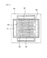
- FIG. 5 illustrates a state in which a fuel gas flows between the first and second separation plates shown in FIG. 2 according to another exemplary embodiment.
- the structure is substantially the same as shown in FIG. 4 , except the structure of the convex for dispersing a fuel gas on all of the conductive film and the second separation plate in contact therewith, and thus like reference numeral denote like structures, and the duplicated detail descriptions will be omitted.
- At least one second channel 384 may be formed in the convex 380 of the first separation plate 350 to flow the fuel gas provided from the openings 482 of the sealing unit 480.
- the second channel 384 may be formed along a perpendicular direction to the second and third sides at which the third fuel holes 470 are formed to flow the fuel gas.
- a plurality of the second channels 384 may be formed at regular intervals in the perpendicular direction.
- the second channels 384 may be formed by partially applying the contact paste on the convex 380 when the conductive film 332 of FIG. 3A is formed.
- the second channels 384 may be formed in a part, facing and contacting the conductive film 332 of FIG. 3A , of the second separation plate 400, not in the convex 330.
- a reducing atmosphere is formed in the convex 380 by the hydrogen included in the fuel gas provided to the second channel 384 from the opening 482, and thus the oxidation of the conductive film 332 of FIG. 3A coating the convex 380 and the second separation plate 450 in electrical contact therewith may be fundamentally prevented.
- the conductive film 332 of FIG. 3A of the convex 380 is not in electrical contact with the second separation plate 450, it is preferable to minimize the number and width of the second channels.
- the width and number of the second channels 384 may be relatively decreased, and as the second channel 384 apart from the opening 482, the width and number may be relatively increased. This is because a pressure of the fuel gas provided from the third fuel holes 470 at the location adjacent to the opening 482 of the sealing unit 480 is higher than at other locations.
- the stack structure may further include manifold-type upper and lower cases 500 and 600, which are respectively disposed on the uppermost and the lowermost thereof, between which the first and second cell modules 100 and 200 are stacked, to protect the first and second cell modules 100 and 200 and the first and second separation plates 300 and 400 from an external environment and provide a total strength.
- First and second connection sockets 510 and 520 connected to an external air provider (not shown) and a fuel gas provider (not shown) may be formed in the upper case 500 to provide the air and the fuel gas to the cathode layer and the anode layer of the fuel cell 110 through the first, second and third air holes 126, 310 and 410 and the first, second and third fuel holes 128, 320 and 420, respectively.
- Such first and second connection sockets 510 and 520 may be respectively formed at sides of the upper case 500 perpendicular to each other to independently provide an air or fuel gas to the cathode layer and the anode layer of the fuel cell 110.
- first and second connection sockets 510 and 520 are formed in the upper case 500, but the above-described function may be sufficiently performed by forming the first and second connection sockets 510 and 520 at the same locations of the lower case 600.
- FIG. 6 is a cross-sectional view illustrating first and second separation plates of a fuel cell stack structure according to another exemplary embodiment of the present invention
- FIGS. 7A and 7B are cross-sectional views specifically illustrating that the first and second separation plates shown in FIG. 6 are connected to each other.
- the structure is substantially the same as those illustrated in FIGS. 2, 3A and 3B , except a structure in which a convex is formed between the first and second separation plates, and since like reference numerals denote like components, duplicated detail descriptions will be omitted.
- a first separation plate 700 of a stack structure 2000 for fuel cells may include a first flat plate 710 having conductivity in which the second air holes 310 of FIG. 1 and second fuel holes 712 are formed, and a second flat plate 720 in contact with a center of the first flat plate 710 to perform the function of the convex 330 of FIG. 2 .
- a second separation plate 800 on which a sealing unit 810 is disposed at an edge and the first flat plate 710 of the first separation plate 700 may have a stable area contact with each other due to the second flat plate 720, an electrical resistance between them may be reduced, and thus electricity generated from the first and second cell modules 100 and 200 may be efficiently collected.
- the first and second flat plates 710 and 720 are manufactured in a simple flat structure in the exemplary embodiment, an additional advantage of easy manufacturing of the stack structure 2000 may be expected.
- first and second conductive films 722 and 724 coated with a contact paste having a conductive material may be formed on both surfaces of the second flat plate 720 facing the first flat plate 710 and the second separation plate 800, respectively. Therefore, even though a surface of the first flat plate 710 is partially uneven, the first and second conductive films 722 and 724 may be evenly formed by predetermined flowability of the contact paste material, and thus the second flat plate 720 may have a more stable electrical contact with the second separation plate 800 while in stable contact with the first flat plate 710.
- the first and second conductive films 722 and 724 may have substantially the same structure as the conductive film 332 shown in FIG. 3A .
- the increase in electrical resistance which may be generated by partial spacing between the first and second flat plates 720 and 710 may be prevented by stably joining the second flat plate 720 to the first flat plate 710 by welding.
- the second flat plate 720 is very stably joined to the first flat plate 710 by welding, even though there is no first conductive film 722 of the second flat plate 720, facing the first flat plate 710, the increase in electrical resistance between them may be prevented.
- the first separation plate 700 includes the first and second flat plates 710 and 720
- the second separation plate 800 includes the first and second flat plates 710 and 720, the same effect may be expected.
- stack structure of the present invention is applied to a solid oxide fuel cell (SOFC) using a ceramic as an electrolyte
- SOFC solid oxide fuel cell
- MCFC molten carbonate fuel cell
- PAFC phosphoric acid fuel cell
- PEFC solid-type fuel cell
- the first and second separation plates which are disposed between the first and second cell modules in which at least one fuel cell is stacked to separate and electrically connecting them, has a convex protruded toward the other separation plate, a stable and even electrical contact between the first and second separation plates can be provided.
- a sealing unit for sealing an air hole and a fuel hole that provide an air including oxygen and a fuel gas including hydrogen to the fuel cell is disposed between the first and second separation plates, a stable electrical contact between the separation plates may be provided by the convex.
- collection efficiency of the fuel cell stack structure in which the first and second cell modules are stacked can be improved by reducing an electrical resistance between the first and second separation plates.
Landscapes
- Life Sciences & Earth Sciences (AREA)
- Engineering & Computer Science (AREA)
- Manufacturing & Machinery (AREA)
- Sustainable Development (AREA)
- Sustainable Energy (AREA)
- Chemical & Material Sciences (AREA)
- Chemical Kinetics & Catalysis (AREA)
- Electrochemistry (AREA)
- General Chemical & Material Sciences (AREA)
- Fuel Cell (AREA)
Applications Claiming Priority (2)
| Application Number | Priority Date | Filing Date | Title |
|---|---|---|---|
| KR1020120146062A KR102055950B1 (ko) | 2012-12-14 | 2012-12-14 | 연료 전지용 스택 구조물 |
| PCT/KR2013/010647 WO2014092357A1 (ko) | 2012-12-14 | 2013-11-21 | 연료 전지용 스택 구조물 |
Publications (3)
| Publication Number | Publication Date |
|---|---|
| EP2933864A1 true EP2933864A1 (de) | 2015-10-21 |
| EP2933864A4 EP2933864A4 (de) | 2016-07-27 |
| EP2933864B1 EP2933864B1 (de) | 2018-10-17 |
Family
ID=50934595
Family Applications (1)
| Application Number | Title | Priority Date | Filing Date |
|---|---|---|---|
| EP13862876.3A Active EP2933864B1 (de) | 2012-12-14 | 2013-11-21 | Stapelstruktur für eine brennstoffzelle |
Country Status (5)
| Country | Link |
|---|---|
| US (1) | US10403908B2 (de) |
| EP (1) | EP2933864B1 (de) |
| KR (1) | KR102055950B1 (de) |
| CN (1) | CN104969397B (de) |
| WO (1) | WO2014092357A1 (de) |
Cited By (1)
| Publication number | Priority date | Publication date | Assignee | Title |
|---|---|---|---|---|
| EP3022793B1 (de) * | 2013-07-16 | 2020-02-26 | Volterion Besitz GmbH & Co. KG | Zelle und zellstack einer redox-flow-batterie |
Families Citing this family (2)
| Publication number | Priority date | Publication date | Assignee | Title |
|---|---|---|---|---|
| KR102140468B1 (ko) * | 2018-12-26 | 2020-08-03 | 한국과학기술연구원 | 스택 내부의 열분포가 개선된 연료전지 |
| CN120727908B (zh) * | 2025-08-21 | 2025-11-14 | 协氢(上海)新能源科技有限公司 | 一种模块化装配式氢燃料电池 |
Family Cites Families (27)
| Publication number | Priority date | Publication date | Assignee | Title |
|---|---|---|---|---|
| US6559352B2 (en) * | 1995-02-21 | 2003-05-06 | Filiberto Zadini | Intravaginal inflatable member for blood leakage prevention |
| DE19713250C2 (de) * | 1997-03-29 | 2002-04-18 | Ballard Power Systems | Elektrochemischer Energiewandler mit Polymerelektrolytmembran |
| JP3456378B2 (ja) * | 1997-08-21 | 2003-10-14 | 株式会社村田製作所 | 固体電解質型燃料電池 |
| US6472094B1 (en) | 1998-07-10 | 2002-10-29 | Kabushiki Kaisha Toyota Chuo Kenkyusho | Separator for fuel cell and manufacture thereof |
| TW504669B (en) * | 1998-09-07 | 2002-10-01 | Ind Tech Res Inst | Vibration suppression device of compact disk drive |
| DE19908555A1 (de) * | 1999-02-27 | 2000-09-28 | Freudenberg Carl Fa | Dichtungsanordnung für großflächige dünne Teile |
| JP4366872B2 (ja) * | 2000-03-13 | 2009-11-18 | トヨタ自動車株式会社 | 燃料電池用ガスセパレータおよび該燃料電池用セパレータの製造方法並びに燃料電池 |
| JP4023669B2 (ja) * | 2001-10-23 | 2007-12-19 | 日本碍子株式会社 | 電気化学装置 |
| US7122266B2 (en) | 2001-09-13 | 2006-10-17 | Ngk Insulators, Ltd. | Holding member for holding an electrochemical cell, a holding substrate for the same, an electrochemical system and a connecting member for electrochemical cells |
| US7125625B2 (en) * | 2002-05-31 | 2006-10-24 | Lynnetech, Inc. | Electrochemical cell and bipolar assembly for an electrochemical cell |
| US7001684B2 (en) * | 2003-01-24 | 2006-02-21 | General Electric Company | Systems for planar fuel cell interconnect units |
| JP2005108616A (ja) | 2003-09-30 | 2005-04-21 | Nichias Corp | 燃料電池用セパレータおよびその製造方法 |
| KR100599776B1 (ko) * | 2004-05-25 | 2006-07-13 | 삼성에스디아이 주식회사 | 연료 전지 시스템 및 그 스택 |
| KR101065380B1 (ko) * | 2004-06-24 | 2011-09-16 | 삼성에스디아이 주식회사 | 연료 전지 시스템 및 이에 사용되는 스택 |
| JP2006127948A (ja) | 2004-10-29 | 2006-05-18 | Nissan Motor Co Ltd | 燃料電池スタック |
| US7763393B2 (en) * | 2005-05-13 | 2010-07-27 | Hitachi Cable, Ltd. | Fuel cell having electrode channel member with comb-teeth shape |
| JP4851761B2 (ja) * | 2005-09-20 | 2012-01-11 | トヨタ自動車株式会社 | 燃料電池 |
| JP4611194B2 (ja) | 2005-12-28 | 2011-01-12 | 本田技研工業株式会社 | 燃料電池及び燃料電池スタック |
| JP5016228B2 (ja) * | 2006-02-01 | 2012-09-05 | 本田技研工業株式会社 | 燃料電池 |
| JP2007328969A (ja) * | 2006-06-07 | 2007-12-20 | Toyota Motor Corp | 燃料電池 |
| JP4936801B2 (ja) | 2006-06-22 | 2012-05-23 | ヤンマー株式会社 | 平板固体酸化物型燃料電池 |
| JP4416038B2 (ja) * | 2008-02-21 | 2010-02-17 | トヨタ自動車株式会社 | 燃料電池 |
| WO2010087298A1 (ja) * | 2009-01-28 | 2010-08-05 | 京セラ株式会社 | 耐熱性合金、燃料電池用合金部材、燃料電池セルスタック装置、燃料電池モジュールおよび燃料電池装置 |
| JP4897928B2 (ja) * | 2009-03-24 | 2012-03-14 | パナソニック株式会社 | 固体高分子形燃料電池および固体高分子形燃料電池用セパレータ |
| KR101071228B1 (ko) * | 2010-10-19 | 2011-10-10 | 김영정 | 고체산화물 연료전지 |
| WO2012133175A1 (ja) * | 2011-03-25 | 2012-10-04 | 株式会社村田製作所 | 燃料電池 |
| CN103460473B (zh) * | 2011-03-30 | 2014-10-15 | 株式会社村田制作所 | 燃料电池 |
-
2012
- 2012-12-14 KR KR1020120146062A patent/KR102055950B1/ko active Active
-
2013
- 2013-11-21 WO PCT/KR2013/010647 patent/WO2014092357A1/ko not_active Ceased
- 2013-11-21 US US14/652,325 patent/US10403908B2/en active Active
- 2013-11-21 EP EP13862876.3A patent/EP2933864B1/de active Active
- 2013-11-21 CN CN201380065489.4A patent/CN104969397B/zh active Active
Cited By (1)
| Publication number | Priority date | Publication date | Assignee | Title |
|---|---|---|---|---|
| EP3022793B1 (de) * | 2013-07-16 | 2020-02-26 | Volterion Besitz GmbH & Co. KG | Zelle und zellstack einer redox-flow-batterie |
Also Published As
| Publication number | Publication date |
|---|---|
| EP2933864A4 (de) | 2016-07-27 |
| US10403908B2 (en) | 2019-09-03 |
| CN104969397A (zh) | 2015-10-07 |
| CN104969397B (zh) | 2018-08-03 |
| KR102055950B1 (ko) | 2019-12-13 |
| WO2014092357A1 (ko) | 2014-06-19 |
| US20150372320A1 (en) | 2015-12-24 |
| EP2933864B1 (de) | 2018-10-17 |
| KR20140077358A (ko) | 2014-06-24 |
Similar Documents
| Publication | Publication Date | Title |
|---|---|---|
| CN101335358B (zh) | 燃料电池 | |
| JP6445182B2 (ja) | インターコネクタ−電気化学反応単セル複合体、電気化学反応セルスタックおよびインターコネクタ−電気化学反応単セル複合体の製造方法 | |
| CN104521052B (zh) | 燃料电池用集电板及包含其的堆结构物 | |
| JP2004087311A (ja) | 燃料電池スタックおよび燃料電池スタック用金属製セパレータ | |
| EP2860806B1 (de) | Stapelstruktur einer brennstoffzelle | |
| EP2933864B1 (de) | Stapelstruktur für eine brennstoffzelle | |
| JP7236966B2 (ja) | 電気化学反応セルスタック | |
| JP2018041569A (ja) | 電気化学反応単位および電気化学反応セルスタック | |
| KR101301824B1 (ko) | 연료 전지용 분리판 | |
| JP6773600B2 (ja) | 電気化学反応単位および電気化学反応セルスタック | |
| US11233250B2 (en) | Electrochemical reaction unit including cathode-side frame configured to improve spreading of oxidant gas and electrochemical reaction cell stack | |
| KR101180157B1 (ko) | 고체 산화물 연료전지의 불량 단위전지 처리장치 및 이의 설치 방법 | |
| JP2013179087A (ja) | 燃料電池 | |
| JP4228895B2 (ja) | 固体酸化物型燃料電池 | |
| JP2018206586A (ja) | 電気化学反応単位、電気化学反応セルスタック、および、電気化学反応単位の製造方法 | |
| JP6368389B1 (ja) | 電気化学反応単位および電気化学反応セルスタック | |
| KR20220104863A (ko) | 요철 패턴을 갖는 고체산화물 연료전지용 분리판 모듈 및 이를 포함하는 연료전지용 스택 | |
| JP2018041570A (ja) | 電気化学反応単位および電気化学反応セルスタック |
Legal Events
| Date | Code | Title | Description |
|---|---|---|---|
| PUAI | Public reference made under article 153(3) epc to a published international application that has entered the european phase |
Free format text: ORIGINAL CODE: 0009012 |
|
| 17P | Request for examination filed |
Effective date: 20150710 |
|
| AK | Designated contracting states |
Kind code of ref document: A1 Designated state(s): AL AT BE BG CH CY CZ DE DK EE ES FI FR GB GR HR HU IE IS IT LI LT LU LV MC MK MT NL NO PL PT RO RS SE SI SK SM TR |
|
| AX | Request for extension of the european patent |
Extension state: BA ME |
|
| RIN1 | Information on inventor provided before grant (corrected) |
Inventor name: CHOI, SUNG JIN Inventor name: CHOI, SONG HO Inventor name: LIM, CHONG SIK Inventor name: HAN, KI MOON |
|
| DAX | Request for extension of the european patent (deleted) | ||
| A4 | Supplementary search report drawn up and despatched |
Effective date: 20160627 |
|
| RIC1 | Information provided on ipc code assigned before grant |
Ipc: H01M 8/0271 20160101ALI20160621BHEP Ipc: H01M 8/0258 20160101ALI20160621BHEP Ipc: H01M 8/2425 20160101ALI20160621BHEP Ipc: H01M 8/24 20060101AFI20160621BHEP Ipc: H01M 8/04 20060101ALI20160621BHEP Ipc: H01M 8/2485 20160101ALI20160621BHEP Ipc: H01M 8/04089 20160101ALI20160621BHEP Ipc: H01M 8/0254 20160101ALI20160621BHEP Ipc: H01M 8/249 20160101ALI20160621BHEP |
|
| RIC1 | Information provided on ipc code assigned before grant |
Ipc: H01M 8/2457 20160101ALI20180306BHEP Ipc: H01M 8/2485 20160101ALI20180306BHEP Ipc: H01M 8/0254 20160101ALI20180306BHEP Ipc: H01M 8/0271 20160101ALI20180306BHEP Ipc: H01M 8/0258 20160101ALI20180306BHEP Ipc: H01M 8/2483 20160101ALI20180306BHEP Ipc: H01M 8/04 20060101ALI20180306BHEP Ipc: H01M 8/2425 20160101ALI20180306BHEP Ipc: H01M 8/04089 20160101ALI20180306BHEP Ipc: H01M 8/249 20160101ALI20180306BHEP Ipc: H01M 8/241 20160101ALI20180306BHEP Ipc: H01M 8/24 20060101AFI20180306BHEP |
|
| GRAP | Despatch of communication of intention to grant a patent |
Free format text: ORIGINAL CODE: EPIDOSNIGR1 |
|
| INTG | Intention to grant announced |
Effective date: 20180426 |
|
| GRAS | Grant fee paid |
Free format text: ORIGINAL CODE: EPIDOSNIGR3 |
|
| GRAA | (expected) grant |
Free format text: ORIGINAL CODE: 0009210 |
|
| AK | Designated contracting states |
Kind code of ref document: B1 Designated state(s): AL AT BE BG CH CY CZ DE DK EE ES FI FR GB GR HR HU IE IS IT LI LT LU LV MC MK MT NL NO PL PT RO RS SE SI SK SM TR |
|
| REG | Reference to a national code |
Ref country code: GB Ref legal event code: FG4D |
|
| REG | Reference to a national code |
Ref country code: CH Ref legal event code: EP |
|
| REG | Reference to a national code |
Ref country code: IE Ref legal event code: FG4D |
|
| REG | Reference to a national code |
Ref country code: DE Ref legal event code: R096 Ref document number: 602013045375 Country of ref document: DE Ref country code: AT Ref legal event code: REF Ref document number: 1055053 Country of ref document: AT Kind code of ref document: T Effective date: 20181115 |
|
| REG | Reference to a national code |
Ref country code: NL Ref legal event code: MP Effective date: 20181017 |
|
| REG | Reference to a national code |
Ref country code: LT Ref legal event code: MG4D |
|
| REG | Reference to a national code |
Ref country code: AT Ref legal event code: MK05 Ref document number: 1055053 Country of ref document: AT Kind code of ref document: T Effective date: 20181017 |
|
| PG25 | Lapsed in a contracting state [announced via postgrant information from national office to epo] |
Ref country code: NL Free format text: LAPSE BECAUSE OF FAILURE TO SUBMIT A TRANSLATION OF THE DESCRIPTION OR TO PAY THE FEE WITHIN THE PRESCRIBED TIME-LIMIT Effective date: 20181017 |
|
| PG25 | Lapsed in a contracting state [announced via postgrant information from national office to epo] |
Ref country code: FI Free format text: LAPSE BECAUSE OF FAILURE TO SUBMIT A TRANSLATION OF THE DESCRIPTION OR TO PAY THE FEE WITHIN THE PRESCRIBED TIME-LIMIT Effective date: 20181017 Ref country code: PL Free format text: LAPSE BECAUSE OF FAILURE TO SUBMIT A TRANSLATION OF THE DESCRIPTION OR TO PAY THE FEE WITHIN THE PRESCRIBED TIME-LIMIT Effective date: 20181017 Ref country code: HR Free format text: LAPSE BECAUSE OF FAILURE TO SUBMIT A TRANSLATION OF THE DESCRIPTION OR TO PAY THE FEE WITHIN THE PRESCRIBED TIME-LIMIT Effective date: 20181017 Ref country code: BG Free format text: LAPSE BECAUSE OF FAILURE TO SUBMIT A TRANSLATION OF THE DESCRIPTION OR TO PAY THE FEE WITHIN THE PRESCRIBED TIME-LIMIT Effective date: 20190117 Ref country code: LV Free format text: LAPSE BECAUSE OF FAILURE TO SUBMIT A TRANSLATION OF THE DESCRIPTION OR TO PAY THE FEE WITHIN THE PRESCRIBED TIME-LIMIT Effective date: 20181017 Ref country code: ES Free format text: LAPSE BECAUSE OF FAILURE TO SUBMIT A TRANSLATION OF THE DESCRIPTION OR TO PAY THE FEE WITHIN THE PRESCRIBED TIME-LIMIT Effective date: 20181017 Ref country code: AT Free format text: LAPSE BECAUSE OF FAILURE TO SUBMIT A TRANSLATION OF THE DESCRIPTION OR TO PAY THE FEE WITHIN THE PRESCRIBED TIME-LIMIT Effective date: 20181017 Ref country code: LT Free format text: LAPSE BECAUSE OF FAILURE TO SUBMIT A TRANSLATION OF THE DESCRIPTION OR TO PAY THE FEE WITHIN THE PRESCRIBED TIME-LIMIT Effective date: 20181017 Ref country code: NO Free format text: LAPSE BECAUSE OF FAILURE TO SUBMIT A TRANSLATION OF THE DESCRIPTION OR TO PAY THE FEE WITHIN THE PRESCRIBED TIME-LIMIT Effective date: 20190117 Ref country code: IS Free format text: LAPSE BECAUSE OF FAILURE TO SUBMIT A TRANSLATION OF THE DESCRIPTION OR TO PAY THE FEE WITHIN THE PRESCRIBED TIME-LIMIT Effective date: 20190217 |
|
| PG25 | Lapsed in a contracting state [announced via postgrant information from national office to epo] |
Ref country code: GR Free format text: LAPSE BECAUSE OF FAILURE TO SUBMIT A TRANSLATION OF THE DESCRIPTION OR TO PAY THE FEE WITHIN THE PRESCRIBED TIME-LIMIT Effective date: 20190118 Ref country code: PT Free format text: LAPSE BECAUSE OF FAILURE TO SUBMIT A TRANSLATION OF THE DESCRIPTION OR TO PAY THE FEE WITHIN THE PRESCRIBED TIME-LIMIT Effective date: 20190217 Ref country code: RS Free format text: LAPSE BECAUSE OF FAILURE TO SUBMIT A TRANSLATION OF THE DESCRIPTION OR TO PAY THE FEE WITHIN THE PRESCRIBED TIME-LIMIT Effective date: 20181017 Ref country code: AL Free format text: LAPSE BECAUSE OF FAILURE TO SUBMIT A TRANSLATION OF THE DESCRIPTION OR TO PAY THE FEE WITHIN THE PRESCRIBED TIME-LIMIT Effective date: 20181017 Ref country code: SE Free format text: LAPSE BECAUSE OF FAILURE TO SUBMIT A TRANSLATION OF THE DESCRIPTION OR TO PAY THE FEE WITHIN THE PRESCRIBED TIME-LIMIT Effective date: 20181017 |
|
| REG | Reference to a national code |
Ref country code: DE Ref legal event code: R097 Ref document number: 602013045375 Country of ref document: DE |
|
| PG25 | Lapsed in a contracting state [announced via postgrant information from national office to epo] |
Ref country code: LU Free format text: LAPSE BECAUSE OF NON-PAYMENT OF DUE FEES Effective date: 20181121 Ref country code: IT Free format text: LAPSE BECAUSE OF FAILURE TO SUBMIT A TRANSLATION OF THE DESCRIPTION OR TO PAY THE FEE WITHIN THE PRESCRIBED TIME-LIMIT Effective date: 20181017 Ref country code: CZ Free format text: LAPSE BECAUSE OF FAILURE TO SUBMIT A TRANSLATION OF THE DESCRIPTION OR TO PAY THE FEE WITHIN THE PRESCRIBED TIME-LIMIT Effective date: 20181017 Ref country code: DK Free format text: LAPSE BECAUSE OF FAILURE TO SUBMIT A TRANSLATION OF THE DESCRIPTION OR TO PAY THE FEE WITHIN THE PRESCRIBED TIME-LIMIT Effective date: 20181017 |
|
| REG | Reference to a national code |
Ref country code: IE Ref legal event code: MM4A |
|
| PLBE | No opposition filed within time limit |
Free format text: ORIGINAL CODE: 0009261 |
|
| STAA | Information on the status of an ep patent application or granted ep patent |
Free format text: STATUS: NO OPPOSITION FILED WITHIN TIME LIMIT |
|
| PG25 | Lapsed in a contracting state [announced via postgrant information from national office to epo] |
Ref country code: MC Free format text: LAPSE BECAUSE OF FAILURE TO SUBMIT A TRANSLATION OF THE DESCRIPTION OR TO PAY THE FEE WITHIN THE PRESCRIBED TIME-LIMIT Effective date: 20181017 Ref country code: SK Free format text: LAPSE BECAUSE OF FAILURE TO SUBMIT A TRANSLATION OF THE DESCRIPTION OR TO PAY THE FEE WITHIN THE PRESCRIBED TIME-LIMIT Effective date: 20181017 Ref country code: EE Free format text: LAPSE BECAUSE OF FAILURE TO SUBMIT A TRANSLATION OF THE DESCRIPTION OR TO PAY THE FEE WITHIN THE PRESCRIBED TIME-LIMIT Effective date: 20181017 Ref country code: SM Free format text: LAPSE BECAUSE OF FAILURE TO SUBMIT A TRANSLATION OF THE DESCRIPTION OR TO PAY THE FEE WITHIN THE PRESCRIBED TIME-LIMIT Effective date: 20181017 Ref country code: RO Free format text: LAPSE BECAUSE OF FAILURE TO SUBMIT A TRANSLATION OF THE DESCRIPTION OR TO PAY THE FEE WITHIN THE PRESCRIBED TIME-LIMIT Effective date: 20181017 |
|
| 26N | No opposition filed |
Effective date: 20190718 |
|
| PG25 | Lapsed in a contracting state [announced via postgrant information from national office to epo] |
Ref country code: IE Free format text: LAPSE BECAUSE OF NON-PAYMENT OF DUE FEES Effective date: 20181121 Ref country code: SI Free format text: LAPSE BECAUSE OF FAILURE TO SUBMIT A TRANSLATION OF THE DESCRIPTION OR TO PAY THE FEE WITHIN THE PRESCRIBED TIME-LIMIT Effective date: 20181017 |
|
| PG25 | Lapsed in a contracting state [announced via postgrant information from national office to epo] |
Ref country code: MT Free format text: LAPSE BECAUSE OF NON-PAYMENT OF DUE FEES Effective date: 20181121 |
|
| PG25 | Lapsed in a contracting state [announced via postgrant information from national office to epo] |
Ref country code: TR Free format text: LAPSE BECAUSE OF FAILURE TO SUBMIT A TRANSLATION OF THE DESCRIPTION OR TO PAY THE FEE WITHIN THE PRESCRIBED TIME-LIMIT Effective date: 20181017 |
|
| PG25 | Lapsed in a contracting state [announced via postgrant information from national office to epo] |
Ref country code: CY Free format text: LAPSE BECAUSE OF FAILURE TO SUBMIT A TRANSLATION OF THE DESCRIPTION OR TO PAY THE FEE WITHIN THE PRESCRIBED TIME-LIMIT Effective date: 20181017 Ref country code: HU Free format text: LAPSE BECAUSE OF FAILURE TO SUBMIT A TRANSLATION OF THE DESCRIPTION OR TO PAY THE FEE WITHIN THE PRESCRIBED TIME-LIMIT; INVALID AB INITIO Effective date: 20131121 Ref country code: MK Free format text: LAPSE BECAUSE OF NON-PAYMENT OF DUE FEES Effective date: 20181017 |
|
| REG | Reference to a national code |
Ref country code: DE Ref legal event code: R082 Ref document number: 602013045375 Country of ref document: DE Representative=s name: CABINET CHAILLOT, FR Ref country code: DE Ref legal event code: R081 Ref document number: 602013045375 Country of ref document: DE Owner name: MICO POWER LTD, ANSEONG-SI, KR Free format text: FORMER OWNER: MICO CO. LTD., ANSEONG-SI, GYEONGGI-DO, KR |
|
| REG | Reference to a national code |
Ref country code: CH Ref legal event code: NV Representative=s name: BRAUNPAT BRAUN EDER AG, CH Ref country code: CH Ref legal event code: PUE Owner name: MICO POWER LTD, KR Free format text: FORMER OWNER: MICO CO. LTD., KR |
|
| REG | Reference to a national code |
Ref country code: BE Ref legal event code: PD Owner name: MICO POWER LTD; KR Free format text: DETAILS ASSIGNMENT: CHANGE OF OWNER(S), ASSIGNMENT; FORMER OWNER NAME: MICO CO. LTD. Effective date: 20210413 |
|
| REG | Reference to a national code |
Ref country code: GB Ref legal event code: 732E Free format text: REGISTERED BETWEEN 20210617 AND 20210623 |
|
| PGFP | Annual fee paid to national office [announced via postgrant information from national office to epo] |
Ref country code: FR Payment date: 20250930 Year of fee payment: 13 |
|
| REG | Reference to a national code |
Ref country code: CH Ref legal event code: U11 Free format text: ST27 STATUS EVENT CODE: U-0-0-U10-U11 (AS PROVIDED BY THE NATIONAL OFFICE) Effective date: 20251201 |
|
| PGFP | Annual fee paid to national office [announced via postgrant information from national office to epo] |
Ref country code: DE Payment date: 20250930 Year of fee payment: 13 |
|
| PGFP | Annual fee paid to national office [announced via postgrant information from national office to epo] |
Ref country code: GB Payment date: 20251001 Year of fee payment: 13 |
|
| PGFP | Annual fee paid to national office [announced via postgrant information from national office to epo] |
Ref country code: BE Payment date: 20251003 Year of fee payment: 13 |
|
| PGFP | Annual fee paid to national office [announced via postgrant information from national office to epo] |
Ref country code: CH Payment date: 20251201 Year of fee payment: 13 |