EP2932984A1 - Procede et systeme de transfert d'energie dans un espace de rinçage d'un automate de nettoyage - Google Patents
Procede et systeme de transfert d'energie dans un espace de rinçage d'un automate de nettoyage Download PDFInfo
- Publication number
- EP2932984A1 EP2932984A1 EP15162217.2A EP15162217A EP2932984A1 EP 2932984 A1 EP2932984 A1 EP 2932984A1 EP 15162217 A EP15162217 A EP 15162217A EP 2932984 A1 EP2932984 A1 EP 2932984A1
- Authority
- EP
- European Patent Office
- Prior art keywords
- washing compartment
- primary coil
- coil
- secondary coil
- ultrasonic
- Prior art date
- Legal status (The legal status is an assumption and is not a legal conclusion. Google has not performed a legal analysis and makes no representation as to the accuracy of the status listed.)
- Granted
Links
Images

Classifications
-
- A—HUMAN NECESSITIES
- A61—MEDICAL OR VETERINARY SCIENCE; HYGIENE
- A61L—METHODS OR APPARATUS FOR STERILISING MATERIALS OR OBJECTS IN GENERAL; DISINFECTION, STERILISATION OR DEODORISATION OF AIR; CHEMICAL ASPECTS OF BANDAGES, DRESSINGS, ABSORBENT PADS OR SURGICAL ARTICLES; MATERIALS FOR BANDAGES, DRESSINGS, ABSORBENT PADS OR SURGICAL ARTICLES
- A61L2/00—Disinfection or sterilisation of materials or objects, in general; Accessories therefor
- A61L2/02—Disinfection or sterilisation of materials or objects, in general; Accessories therefor using physical processes
- A61L2/025—Ultrasonic waves
-
- H—ELECTRICITY
- H02—GENERATION; CONVERSION OR DISTRIBUTION OF ELECTRIC POWER
- H02J—ELECTRIC POWER NETWORKS; CIRCUIT ARRANGEMENTS OR SYSTEMS FOR SUPPLYING OR DISTRIBUTING ELECTRIC POWER; SYSTEMS FOR STORING ELECTRIC ENERGY
- H02J50/00—Circuit arrangements or systems for wireless supply or distribution of electric power
- H02J50/10—Circuit arrangements or systems for wireless supply or distribution of electric power using inductive coupling
-
- H—ELECTRICITY
- H02—GENERATION; CONVERSION OR DISTRIBUTION OF ELECTRIC POWER
- H02J—ELECTRIC POWER NETWORKS; CIRCUIT ARRANGEMENTS OR SYSTEMS FOR SUPPLYING OR DISTRIBUTING ELECTRIC POWER; SYSTEMS FOR STORING ELECTRIC ENERGY
- H02J50/00—Circuit arrangements or systems for wireless supply or distribution of electric power
- H02J50/70—Circuit arrangements or systems for wireless supply or distribution of electric power involving the reduction of electric, magnetic or electromagnetic leakage fields
Definitions
- the invention relates to a method and an arrangement for the transmission of electrical energy in a washing compartment of a cleaning machine, in particular a cleaning machine for medical instruments.
- the treatment here includes a cleaning, disinfection, drying and possibly a subsequent sterilization.
- the steps of cleaning, disinfecting and drying are usually performed in a washer-disinfector, also referred to as a cleaning machine.
- a cleaning machine also referred to as a cleaning machine.
- automatic dishwashers working with dishwashers having at least one spray arm, via which a cleaning liquid is sprayed in the washing compartment, have become established.
- the cleaning machines are often built in the form of locks, so that instruments are transferred from a non-disinfected area by the cleaning machine as a lock in a disinfected area.
- a method for the transmission of electrical energy into a washing compartment of a cleaning machine is characterized in that a secondary coil coupled to a power consumer arranged in the washing compartment is brought into an effective region of a primary coil fixedly attached to a wall of the washing compartment and energy is inductively applied from the primary coil to the primary coil Secondary coil is transmitted.
- the inductive energy transfer is contactless. Compared to an energy transfer with contacts protection against the ingress of water or penetrating cleaning liquid can be implemented structurally simple in a contactless energy transfer within the washing compartment. In addition, there is no risk of contact corrosion in the contactless energy transfer, which would preclude a safe and reliable energy transfer and would otherwise be difficult to prevent just in the humid and warm atmosphere in the sink otherwise.
- the primary coil is subjected to an alternating voltage in a frequency range between 20 kHz and 200 kHz, in particular between 20 kHz and 40 kHz. In this frequency range, an effective energy transfer can take place with relatively small coils.
- an alternating voltage induced in the secondary coil is fed directly to the current consumer.
- the alternating voltage induced in the secondary coil is supplied to at least one ultrasonic transducer as a current consumer.
- the energy transfer method described is particularly suitable for the power supply of ultrasonic transducers, which are arranged within the washing compartment, as they can be readily operated directly with the induced in the secondary coil AC voltage when the primary coil is applied accordingly with AC voltage of a frequency in the ultrasonic range.
- An arrangement according to the invention for the transmission of electrical energy into a washing compartment of a cleaning machine has a primary coil which is stationary in the washing compartment and a secondary coil which can be introduced into the effective region of the primary coil.
- the secondary coil is directly connected to a power consumer in the washing compartment.
- the primary coil and the secondary coil are preferably designed for transmitting an alternating voltage in a frequency range between 20 kHz and 200 kHz, in particular between 20 kHz and 40 kHz.
- the arrangement is designed for at least one ultrasonic transducer as a power consumer, for example by the secondary coil and / or the primary coil is tuned to the at least one ultrasonic transducer with regard to their impedance, their number of turns and Windungsiere tone.
- the primary coil and / or the secondary coil designed as a spiral coil. It is thus achieved a particularly flat construction, which can be well arranged in the region of a side wall of the washing compartment.
- the primary coil is arranged in a one-piece housing which can be fixed by means of a threaded piece and a union nut in a mounting opening of a wall of the washing compartment. It is thus created in a simple way a sprühwasser Why attachment for the primary coil.
- a ferrite shield is preferably arranged in the housing on one side of the primary coil. The ferrite shield, for example in the form of flat ferrite segments, prevents the induction of energy-consuming eddy currents in the wall of the washing compartment.
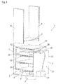
- FIG. 1 shows in a perspective partially sectioned view of a cleaning machine 1 for cleaning medical instruments.
- the cleaning machine 1 has a washing compartment 2, which is bounded by side walls 3, a bottom 4 and a ceiling 5.
- Forward and rear doors 6 are provided, designed in this embodiment as vertically movable doors. The arrangement of two themselves opposite doors 6 makes it possible to install the cleaning machine 1 in the manner of a lock between a non-disinfected area and a disinfected area of a doctor's office or an operating area.
- a purging pot 7 is arranged, in which in the cleaning machine 1 circulating cleaning liquid, also called rinsing, collects.
- the cleaning liquid is sprayed from the flushing pot 7 after filtering and possibly further cleaning by a pump via a spray arm 8 in the washing compartment 2 for cleaning introduced items to be washed.
- a spray arm 8 in the washing compartment 2 for cleaning introduced items to be washed.
- a Spülgutwagen 10 is provided, can be granted in the dishes on several levels 11. Within the Spülgutwagens 10 further spray arms 12 are arranged in the individual levels 11, is also pumped into the cleaning liquid from the rinse liquor of the cleaning machine 1. For clarity, the levels 11 are shown closed. In an implementation of the cleaning machine 1, the levels 11 are made of a wire mesh material, for example, so that cleaning liquid can reach the items to be washed from all sides.
- a hydraulic clutch not shown here, is provided.
- the cleaning machine 1 is prepared for receiving an ultrasonic module 20, which can be used in the washing compartment 2 and with the particularly stubbornly soiled instruments can be cleaned extra and particularly intense.
- the ultrasonic module 20 can be used in one or more of the levels 11 of the Spülgutwagens 10.
- the cleaning effect is achieved by irradiation of ultrasonic waves on the instruments, for which electrical energy is required, which is transmitted from an application according to the arrangement for the transmission of electrical energy in the washing compartment 2. This is below in connection with the FIGS. 2 to 4 shown in more detail.
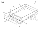
- the ultrasound module 20 is in the FIG. 2 shown in more detail in a likewise perspective and partially sectional view.
- the ultrasonic module 20 comprises an ultrasonic tub 21, which is open at the top and has a storage surface 22 for the items to be washed down.
- the storage surface 22 may be structured to give a lateral support to applied instruments to be cleaned. It can also be provided that the instruments to be cleaned are used in holders, not shown here, in order not to touch the support surface 22 itself or the edges of the ultrasonic tub 21. For more sensitive items this serves to protect against mechanical damage.
- the ultrasonic tub 21 has a drain 23, which consists of one or more lateral bores in the example shown.
- a drain 23 which consists of one or more lateral bores in the example shown.
- cleaning liquid is distributed via the spray arms or the further spray arms 12 in the washing compartment 2 and passes from above into the ultrasonic tub 21.
- the diameter of the drain 23 is dimensioned so that only at a higher level of the cleaning liquid in the ultrasonic tub 21 is a balance between the incoming amount of cleaning liquid and the running through the bore 23 amount of cleaning liquid. In this way it is achieved that during operation of the cleaning machine 1, at least in certain rinsing phases of the cleaning machine 1, the ware inserted into the ultrasonic trough 21 is at least partially and preferably completely surrounded by cleaning liquid. In such an operating state of the cleaning machine 1, an ultrasonic cleaning of the items to be washed in the ultrasonic tub 21 can take place.
- the outlet 23 may be provided with an electrically controllable valve.
- the filling of the ultrasonic tub 21 with the cleaning liquid or the draining off of the cleaning liquid can be controlled in a targeted manner. It is also possible to use a thermally controlled valve which, due to the different temperatures during the cleaning process, suitably opens or closes the drain 23.
- the ultrasound module 20 has ultrasound transducers 26, which are arranged in a closed enclosure 25 adjacent to the ultrasound pan 21.
- the ultrasonic transducers 26 act directly on a dividing wall 24 which is a side wall of the ultrasonic trough 21 and separates the ultrasonic trough 21 from the housing 25 of the ultrasonic transducers 26.
- four juxtaposed ultrasonic transducers 26 are provided.
- These ultrasonic transducers 26 are, for example, piezoelectrically operating transducers, the oscillations in the ultrasonic range, for example between 20 kilohertz (kHz) and 200 kHz and in particular between 20 kHz and 40 kHz, on the partition wall 24 and thus on the cleaning liquid to the arranged in the ultrasonic tub 21 items to be washed transfer.
- kHz kilohertz
- 40 kHz the cleaning liquid to the arranged in the ultrasonic tub 21 items to be washed transfer.
- the ultrasonic transducers 26 are connected via an electrical cable 27 to a secondary coil 281, which is arranged in a coupling element 28.
- an ultrasonic generator unit 30 On one of the side walls 3 of the cleaning machine 1, an ultrasonic generator unit 30 is arranged, which has an ultrasonic signal generator 31 which is connected via a cable 32 with a coupling counterpart 33.
- the ultrasound signal generator 31 generates an electrical signal AC signal generated in the aforementioned frequency range from 20 kHz to about 200 kHz, which is transmitted via the cable 32 to a arranged in the coupling counterpart 33 primary coil 331.
- the cable 32 is preferably shielded, as well as the cable 27, so that no interfering radiation is emitted.
- the primary coil 331 of the coupling counterpart 33 transmits electrical energy provided by the ultrasonic signal generator 31 inductively to the secondary coil 281 of the coupling element 28 of the ultrasonic module 20.
- the coupling element 28 and the coupling counterpart 33 are sealed so that the secondary or primary coils 281 and 331 splash before Cleaning liquid in the washing compartment 2 are protected.
- the coupling counterpart 33 is also arranged waterproof in the side wall 3.
- the arrangement for transmitting the electrical energy into the washing compartment 2, comprising the primary coil 331 and the secondary coil 281, is in the FIG. 3 again shown schematically.
- an alternating magnetic field 9 via which the energy is transmitted indicated.
- the energy transfer from the primary coil 331 and the secondary coil 281 takes place in the illustrated embodiment at the frequency at which the ultrasonic transducers 26 are operated.
- the ultrasonic transducers 26 as current consumers can consequently be connected directly to the secondary coil 281.
- the ultrasonic generator unit 30 can be arranged outside the washing compartment 2, and no further electronic components are required in the washing compartment 2 itself, which has several advantages.
- high temperatures that can rise to about 95 ° C in the disinfection phase and in the drying phase to about 120 ° C. Such high temperatures may be problematic for electronic components and may shorten their life.
- the coupling element 28 is manually attached to the coupling counterpart 33 and connected to this and possibly locked. This connection or locking is then also solved manually before the Spülgutwagen is removed to the other side of the cleaning machine 1 after cleaning. It is alternatively conceivable that the coupling element 28 is inserted into a holder on Spülgutwagen 10, wherein this holder is arranged so that when inserting the Spülgutwagens 10, the coupling element 28 is suitably positioned in front of the coupling counterpart 33, so that the inductive energy transfer can take place.
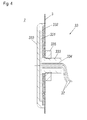
- FIG. 4 shows a sectional view of an embodiment of a coupling counterpart 33 for an arrangement for the transmission of electrical energy in a washing compartment 2 of a cleaning machine.
- the coupling counterpart 33 is inserted through an opening in a side wall 3 of a cleaning machine, for example, the in FIG. 1
- a circular mounting opening in this case is required in a wall, here in a side wall 3, which surrounds the washing compartment 2.
- the washing compartment 2 on the left side of the side wall. 3
- the coupling counterpart 33 has a primary coil 331, which is spirally wound in the illustrated embodiment. With such a spiral coil, a flat as possible construction of the coupling counterpart 33 can be achieved.
- ferrite segments 332 for shielding a magnetic field of the coil 331 are arranged. This thus formed ferrite shield prevents penetration of magnetic field lines in the usually metallic side wall 3, in the otherwise lossy eddy currents would be induced.
- the ferrite segments 332 protrude radially beyond the radius of the primary coil 331.
- the arrangement of primary coil 331 and ferrite segments 332 is arranged in a one-piece housing 333.
- the housing 333 completely encloses the primary coil 331 and the ferrite segments 332 in the region of the washing compartment 2.
- the housing 333 merges with the opposite side into a threaded piece, which is inserted through the aforementioned opening in the side wall 3.
- a cable bushing 334 is inserted, are guided by the connecting cable 32 for the primary coil 331.
- the threaded portion of the housing 333 is provided with a thread on which a cap nut 335 is screwed, with which the housing 333 and thus the entire coupling counterpart 33 is fixed to the side wall 3.
- a groove for receiving an O-ring may be introduced into the housing 333 in the area lying in the washing chamber 2 and applied to the side wall 3, with which the housing 333 is sealed in the region of the union nut 335 against the side wall 3, to escape to prevent moisture from the washing compartment 2 through the mounting hole in the side wall 3.
- the housing 333 is preferably made of a heat-resistant and resistant to the cleaning liquid used plastic material. It can first be produced in two parts, which after insertion of the primary coil 331 and the ferrite segments 332 and optionally the cable bushing 334 are preferably inseparably connected to one another, for example welded, in particular plasma-welded.
- the coupling counterpart 33 has the best possible protection against penetrating water and a very flat structure.
- a simple installation in the cleaning machine 1 is given.
Landscapes
- Engineering & Computer Science (AREA)
- Computer Networks & Wireless Communication (AREA)
- Power Engineering (AREA)
- Health & Medical Sciences (AREA)
- Epidemiology (AREA)
- Life Sciences & Earth Sciences (AREA)
- Animal Behavior & Ethology (AREA)
- General Health & Medical Sciences (AREA)
- Public Health (AREA)
- Veterinary Medicine (AREA)
- Physics & Mathematics (AREA)
- Electromagnetism (AREA)
- Cleaning By Liquid Or Steam (AREA)
Applications Claiming Priority (1)
| Application Number | Priority Date | Filing Date | Title |
|---|---|---|---|
| DE102014104622 | 2014-04-02 |
Publications (2)
| Publication Number | Publication Date |
|---|---|
| EP2932984A1 true EP2932984A1 (fr) | 2015-10-21 |
| EP2932984B1 EP2932984B1 (fr) | 2016-11-16 |
Family
ID=53682471
Family Applications (1)
| Application Number | Title | Priority Date | Filing Date |
|---|---|---|---|
| EP15162217.2A Active EP2932984B1 (fr) | 2014-04-02 | 2015-04-01 | Procede et systeme de transfert d'energie dans un espace de rinçage d'un automate de nettoyage |
Country Status (1)
| Country | Link |
|---|---|
| EP (1) | EP2932984B1 (fr) |
Cited By (1)
| Publication number | Priority date | Publication date | Assignee | Title |
|---|---|---|---|---|
| EP2974746A3 (fr) * | 2014-04-02 | 2016-05-25 | Miele & Cie. KG | Automate de nettoyage et module à ultrasons pour instruments médicaux |
Citations (4)
| Publication number | Priority date | Publication date | Assignee | Title |
|---|---|---|---|---|
| EP0678275A1 (fr) * | 1994-04-21 | 1995-10-25 | AEG Hausgeräte GmbH | Lave-vaisselle comportant un dispositif de dosage |
| CH696020A5 (de) * | 2004-06-23 | 2006-11-30 | V Zug Ag | Haushaltgerät mit Eingabe- und/oder Anzeigeeinheit. |
| DE102006007169A1 (de) * | 2006-02-08 | 2007-08-09 | E.G.O. Elektro-Gerätebau GmbH | Vorrichtung und Verfahren zum Betrieb eines Elektrogerätes mit einer außen ansetzbaren Bedieneinrichtung |
| WO2009085292A1 (fr) * | 2007-12-21 | 2009-07-09 | Dentsply International Inc. | Insert dentaire à ultrasons et ensemble de pièce à main éclairé |
-
2015
- 2015-04-01 EP EP15162217.2A patent/EP2932984B1/fr active Active
Patent Citations (4)
| Publication number | Priority date | Publication date | Assignee | Title |
|---|---|---|---|---|
| EP0678275A1 (fr) * | 1994-04-21 | 1995-10-25 | AEG Hausgeräte GmbH | Lave-vaisselle comportant un dispositif de dosage |
| CH696020A5 (de) * | 2004-06-23 | 2006-11-30 | V Zug Ag | Haushaltgerät mit Eingabe- und/oder Anzeigeeinheit. |
| DE102006007169A1 (de) * | 2006-02-08 | 2007-08-09 | E.G.O. Elektro-Gerätebau GmbH | Vorrichtung und Verfahren zum Betrieb eines Elektrogerätes mit einer außen ansetzbaren Bedieneinrichtung |
| WO2009085292A1 (fr) * | 2007-12-21 | 2009-07-09 | Dentsply International Inc. | Insert dentaire à ultrasons et ensemble de pièce à main éclairé |
Cited By (1)
| Publication number | Priority date | Publication date | Assignee | Title |
|---|---|---|---|---|
| EP2974746A3 (fr) * | 2014-04-02 | 2016-05-25 | Miele & Cie. KG | Automate de nettoyage et module à ultrasons pour instruments médicaux |
Also Published As
| Publication number | Publication date |
|---|---|
| EP2932984B1 (fr) | 2016-11-16 |
Similar Documents
| Publication | Publication Date | Title |
|---|---|---|
| DE69631797T2 (de) | Spülmaschine und Verfahren unter Verwendung der Spülmaschine | |
| DE102007025245A1 (de) | Erwärmung eines Tankinhaltes durch Mikrowellen | |
| DE102010027795A1 (de) | Hausgerät mit Plasmagenerator und Verfahren zu seinem Betrieb | |
| WO2010006920A1 (fr) | Système de production de plasma | |
| DE102018221814A1 (de) | PEF-Gargerät und PEF-System | |
| WO2009007456A2 (fr) | Dispositif pour ajouter de l'eau pour la production de vapeur dans un appareil de cuisson | |
| DE202018100836U1 (de) | Rasenmäher | |
| DE3425590A1 (de) | Sicherheitsvorrichtung gegen ueberschwemmung bei fluessigkeitsfuehrenden haushaltgeraeten | |
| EP2932984B1 (fr) | Procede et systeme de transfert d'energie dans un espace de rinçage d'un automate de nettoyage | |
| DE69502530T2 (de) | Kanüle zum Absaugen von Fettgeweben und Handgriff dafür | |
| EP1862099A2 (fr) | Appareil de cuisine doté d'un générateur de vapeur et dispositif de chauffage abaissable | |
| DE102010038690A1 (de) | Wasserführendes Haushaltsgerät, insbesondere Geschirrspülmaschine | |
| EP2974746B1 (fr) | Automate de nettoyage avec module à ultrasons pour instruments médicaux | |
| DE202015100306U1 (de) | Wäschebehandlungsvorrichtung mit Dampfgenerator | |
| DE102016110544A1 (de) | Waschautomat zum Waschen von Wäsche | |
| DE102014224097A1 (de) | Ablauf- und Filtereinrichtung für eine Waschmaschine | |
| DE10317787B3 (de) | Programmgesteuerte Spülmaschine mit einem Sicherheitsüberlauf | |
| EP3963264B1 (fr) | Appareil domestique de traitement à la vapeur et procédé pour faire fonctionner un appareil domestique de traitement à la vapeur | |
| DE20001087U1 (de) | Haushaltsgerät | |
| DE3641659C1 (de) | Vorrichtung zur Waermebehandlung von Substanzen,insbesondere Nahrungsmitteln | |
| EP0222174B1 (fr) | Appareil domestique utilisant de l'eau | |
| DE19747674A1 (de) | Wasserführendes elektrisches Haushaltsgerät, wie Wasch- oder Geschirrspülmaschine | |
| DE102008035787B4 (de) | Dampferzeuger sowie Kleidungsbehandlungsmaschine und Geschirrspülmaschine mit einem Dampferzeuger | |
| DE102017108349A1 (de) | Wasch- oder Spülmaschine mit einer Heizeinrichtung zur Aufheizung der Wasch- oder Spülflüssigkeit | |
| EP0915197A2 (fr) | Machine domestique avec tuyaux d'eau |
Legal Events
| Date | Code | Title | Description |
|---|---|---|---|
| PUAI | Public reference made under article 153(3) epc to a published international application that has entered the european phase |
Free format text: ORIGINAL CODE: 0009012 |
|
| AK | Designated contracting states |
Kind code of ref document: A1 Designated state(s): AL AT BE BG CH CY CZ DE DK EE ES FI FR GB GR HR HU IE IS IT LI LT LU LV MC MK MT NL NO PL PT RO RS SE SI SK SM TR |
|
| AX | Request for extension of the european patent |
Extension state: BA ME |
|
| 17P | Request for examination filed |
Effective date: 20160421 |
|
| RBV | Designated contracting states (corrected) |
Designated state(s): AL AT BE BG CH CY CZ DE DK EE ES FI FR GB GR HR HU IE IS IT LI LT LU LV MC MK MT NL NO PL PT RO RS SE SI SK SM TR |
|
| GRAJ | Information related to disapproval of communication of intention to grant by the applicant or resumption of examination proceedings by the epo deleted |
Free format text: ORIGINAL CODE: EPIDOSDIGR1 |
|
| GRAP | Despatch of communication of intention to grant a patent |
Free format text: ORIGINAL CODE: EPIDOSNIGR1 |
|
| GRAP | Despatch of communication of intention to grant a patent |
Free format text: ORIGINAL CODE: EPIDOSNIGR1 |
|
| INTG | Intention to grant announced |
Effective date: 20160708 |
|
| GRAS | Grant fee paid |
Free format text: ORIGINAL CODE: EPIDOSNIGR3 |
|
| GRAA | (expected) grant |
Free format text: ORIGINAL CODE: 0009210 |
|
| AK | Designated contracting states |
Kind code of ref document: B1 Designated state(s): AL AT BE BG CH CY CZ DE DK EE ES FI FR GB GR HR HU IE IS IT LI LT LU LV MC MK MT NL NO PL PT RO RS SE SI SK SM TR |
|
| REG | Reference to a national code |
Ref country code: GB Ref legal event code: FG4D Free format text: NOT ENGLISH |
|
| REG | Reference to a national code |
Ref country code: DE Ref legal event code: R084 Ref document number: 502015000295 Country of ref document: DE |
|
| REG | Reference to a national code |
Ref country code: CH Ref legal event code: EP |
|
| REG | Reference to a national code |
Ref country code: GB Ref legal event code: 746 Effective date: 20161115 |
|
| REG | Reference to a national code |
Ref country code: IE Ref legal event code: FG4D Free format text: LANGUAGE OF EP DOCUMENT: GERMAN |
|
| REG | Reference to a national code |
Ref country code: AT Ref legal event code: REF Ref document number: 845289 Country of ref document: AT Kind code of ref document: T Effective date: 20161215 |
|
| REG | Reference to a national code |
Ref country code: DE Ref legal event code: R096 Ref document number: 502015000295 Country of ref document: DE |
|
| PG25 | Lapsed in a contracting state [announced via postgrant information from national office to epo] |
Ref country code: LV Free format text: LAPSE BECAUSE OF FAILURE TO SUBMIT A TRANSLATION OF THE DESCRIPTION OR TO PAY THE FEE WITHIN THE PRESCRIBED TIME-LIMIT Effective date: 20161116 |
|
| REG | Reference to a national code |
Ref country code: NL Ref legal event code: MP Effective date: 20161116 |
|
| REG | Reference to a national code |
Ref country code: LT Ref legal event code: MG4D |
|
| REG | Reference to a national code |
Ref country code: FR Ref legal event code: PLFP Year of fee payment: 3 |
|
| PG25 | Lapsed in a contracting state [announced via postgrant information from national office to epo] |
Ref country code: GR Free format text: LAPSE BECAUSE OF FAILURE TO SUBMIT A TRANSLATION OF THE DESCRIPTION OR TO PAY THE FEE WITHIN THE PRESCRIBED TIME-LIMIT Effective date: 20170217 Ref country code: LT Free format text: LAPSE BECAUSE OF FAILURE TO SUBMIT A TRANSLATION OF THE DESCRIPTION OR TO PAY THE FEE WITHIN THE PRESCRIBED TIME-LIMIT Effective date: 20161116 Ref country code: NO Free format text: LAPSE BECAUSE OF FAILURE TO SUBMIT A TRANSLATION OF THE DESCRIPTION OR TO PAY THE FEE WITHIN THE PRESCRIBED TIME-LIMIT Effective date: 20170216 Ref country code: NL Free format text: LAPSE BECAUSE OF FAILURE TO SUBMIT A TRANSLATION OF THE DESCRIPTION OR TO PAY THE FEE WITHIN THE PRESCRIBED TIME-LIMIT Effective date: 20161116 Ref country code: SE Free format text: LAPSE BECAUSE OF FAILURE TO SUBMIT A TRANSLATION OF THE DESCRIPTION OR TO PAY THE FEE WITHIN THE PRESCRIBED TIME-LIMIT Effective date: 20161116 |
|
| PG25 | Lapsed in a contracting state [announced via postgrant information from national office to epo] |
Ref country code: ES Free format text: LAPSE BECAUSE OF FAILURE TO SUBMIT A TRANSLATION OF THE DESCRIPTION OR TO PAY THE FEE WITHIN THE PRESCRIBED TIME-LIMIT Effective date: 20161116 Ref country code: PL Free format text: LAPSE BECAUSE OF FAILURE TO SUBMIT A TRANSLATION OF THE DESCRIPTION OR TO PAY THE FEE WITHIN THE PRESCRIBED TIME-LIMIT Effective date: 20161116 Ref country code: FI Free format text: LAPSE BECAUSE OF FAILURE TO SUBMIT A TRANSLATION OF THE DESCRIPTION OR TO PAY THE FEE WITHIN THE PRESCRIBED TIME-LIMIT Effective date: 20161116 Ref country code: RS Free format text: LAPSE BECAUSE OF FAILURE TO SUBMIT A TRANSLATION OF THE DESCRIPTION OR TO PAY THE FEE WITHIN THE PRESCRIBED TIME-LIMIT Effective date: 20161116 Ref country code: PT Free format text: LAPSE BECAUSE OF FAILURE TO SUBMIT A TRANSLATION OF THE DESCRIPTION OR TO PAY THE FEE WITHIN THE PRESCRIBED TIME-LIMIT Effective date: 20170316 Ref country code: HR Free format text: LAPSE BECAUSE OF FAILURE TO SUBMIT A TRANSLATION OF THE DESCRIPTION OR TO PAY THE FEE WITHIN THE PRESCRIBED TIME-LIMIT Effective date: 20161116 |
|
| PG25 | Lapsed in a contracting state [announced via postgrant information from national office to epo] |
Ref country code: CZ Free format text: LAPSE BECAUSE OF FAILURE TO SUBMIT A TRANSLATION OF THE DESCRIPTION OR TO PAY THE FEE WITHIN THE PRESCRIBED TIME-LIMIT Effective date: 20161116 Ref country code: RO Free format text: LAPSE BECAUSE OF FAILURE TO SUBMIT A TRANSLATION OF THE DESCRIPTION OR TO PAY THE FEE WITHIN THE PRESCRIBED TIME-LIMIT Effective date: 20161116 Ref country code: DK Free format text: LAPSE BECAUSE OF FAILURE TO SUBMIT A TRANSLATION OF THE DESCRIPTION OR TO PAY THE FEE WITHIN THE PRESCRIBED TIME-LIMIT Effective date: 20161116 Ref country code: EE Free format text: LAPSE BECAUSE OF FAILURE TO SUBMIT A TRANSLATION OF THE DESCRIPTION OR TO PAY THE FEE WITHIN THE PRESCRIBED TIME-LIMIT Effective date: 20161116 Ref country code: SK Free format text: LAPSE BECAUSE OF FAILURE TO SUBMIT A TRANSLATION OF THE DESCRIPTION OR TO PAY THE FEE WITHIN THE PRESCRIBED TIME-LIMIT Effective date: 20161116 |
|
| REG | Reference to a national code |
Ref country code: DE Ref legal event code: R097 Ref document number: 502015000295 Country of ref document: DE |
|
| PG25 | Lapsed in a contracting state [announced via postgrant information from national office to epo] |
Ref country code: SM Free format text: LAPSE BECAUSE OF FAILURE TO SUBMIT A TRANSLATION OF THE DESCRIPTION OR TO PAY THE FEE WITHIN THE PRESCRIBED TIME-LIMIT Effective date: 20161116 Ref country code: BG Free format text: LAPSE BECAUSE OF FAILURE TO SUBMIT A TRANSLATION OF THE DESCRIPTION OR TO PAY THE FEE WITHIN THE PRESCRIBED TIME-LIMIT Effective date: 20170216 |
|
| PLBE | No opposition filed within time limit |
Free format text: ORIGINAL CODE: 0009261 |
|
| STAA | Information on the status of an ep patent application or granted ep patent |
Free format text: STATUS: NO OPPOSITION FILED WITHIN TIME LIMIT |
|
| 26N | No opposition filed |
Effective date: 20170817 |
|
| PG25 | Lapsed in a contracting state [announced via postgrant information from national office to epo] |
Ref country code: SI Free format text: LAPSE BECAUSE OF FAILURE TO SUBMIT A TRANSLATION OF THE DESCRIPTION OR TO PAY THE FEE WITHIN THE PRESCRIBED TIME-LIMIT Effective date: 20161116 |
|
| REG | Reference to a national code |
Ref country code: IE Ref legal event code: MM4A |
|
| PG25 | Lapsed in a contracting state [announced via postgrant information from national office to epo] |
Ref country code: MC Free format text: LAPSE BECAUSE OF FAILURE TO SUBMIT A TRANSLATION OF THE DESCRIPTION OR TO PAY THE FEE WITHIN THE PRESCRIBED TIME-LIMIT Effective date: 20161116 |
|
| PG25 | Lapsed in a contracting state [announced via postgrant information from national office to epo] |
Ref country code: LU Free format text: LAPSE BECAUSE OF NON-PAYMENT OF DUE FEES Effective date: 20170401 |
|
| REG | Reference to a national code |
Ref country code: BE Ref legal event code: MM Effective date: 20170430 |
|
| REG | Reference to a national code |
Ref country code: FR Ref legal event code: PLFP Year of fee payment: 4 |
|
| PG25 | Lapsed in a contracting state [announced via postgrant information from national office to epo] |
Ref country code: IE Free format text: LAPSE BECAUSE OF NON-PAYMENT OF DUE FEES Effective date: 20170401 |
|
| PG25 | Lapsed in a contracting state [announced via postgrant information from national office to epo] |
Ref country code: BE Free format text: LAPSE BECAUSE OF NON-PAYMENT OF DUE FEES Effective date: 20170430 |
|
| PG25 | Lapsed in a contracting state [announced via postgrant information from national office to epo] |
Ref country code: MT Free format text: LAPSE BECAUSE OF FAILURE TO SUBMIT A TRANSLATION OF THE DESCRIPTION OR TO PAY THE FEE WITHIN THE PRESCRIBED TIME-LIMIT Effective date: 20161116 |
|
| REG | Reference to a national code |
Ref country code: CH Ref legal event code: PL |
|
| PG25 | Lapsed in a contracting state [announced via postgrant information from national office to epo] |
Ref country code: LI Free format text: LAPSE BECAUSE OF NON-PAYMENT OF DUE FEES Effective date: 20180430 Ref country code: CH Free format text: LAPSE BECAUSE OF NON-PAYMENT OF DUE FEES Effective date: 20180430 |
|
| PG25 | Lapsed in a contracting state [announced via postgrant information from national office to epo] |
Ref country code: HU Free format text: LAPSE BECAUSE OF FAILURE TO SUBMIT A TRANSLATION OF THE DESCRIPTION OR TO PAY THE FEE WITHIN THE PRESCRIBED TIME-LIMIT; INVALID AB INITIO Effective date: 20150401 |
|
| PG25 | Lapsed in a contracting state [announced via postgrant information from national office to epo] |
Ref country code: CY Free format text: LAPSE BECAUSE OF FAILURE TO SUBMIT A TRANSLATION OF THE DESCRIPTION OR TO PAY THE FEE WITHIN THE PRESCRIBED TIME-LIMIT Effective date: 20161116 |
|
| PG25 | Lapsed in a contracting state [announced via postgrant information from national office to epo] |
Ref country code: MK Free format text: LAPSE BECAUSE OF FAILURE TO SUBMIT A TRANSLATION OF THE DESCRIPTION OR TO PAY THE FEE WITHIN THE PRESCRIBED TIME-LIMIT Effective date: 20161116 |
|
| PG25 | Lapsed in a contracting state [announced via postgrant information from national office to epo] |
Ref country code: TR Free format text: LAPSE BECAUSE OF FAILURE TO SUBMIT A TRANSLATION OF THE DESCRIPTION OR TO PAY THE FEE WITHIN THE PRESCRIBED TIME-LIMIT Effective date: 20161116 |
|
| PG25 | Lapsed in a contracting state [announced via postgrant information from national office to epo] |
Ref country code: AL Free format text: LAPSE BECAUSE OF FAILURE TO SUBMIT A TRANSLATION OF THE DESCRIPTION OR TO PAY THE FEE WITHIN THE PRESCRIBED TIME-LIMIT Effective date: 20161116 Ref country code: IS Free format text: LAPSE BECAUSE OF FAILURE TO SUBMIT A TRANSLATION OF THE DESCRIPTION OR TO PAY THE FEE WITHIN THE PRESCRIBED TIME-LIMIT Effective date: 20170316 |
|
| REG | Reference to a national code |
Ref country code: AT Ref legal event code: MM01 Ref document number: 845289 Country of ref document: AT Kind code of ref document: T Effective date: 20200401 |
|
| PG25 | Lapsed in a contracting state [announced via postgrant information from national office to epo] |
Ref country code: AT Free format text: LAPSE BECAUSE OF NON-PAYMENT OF DUE FEES Effective date: 20200401 |
|
| P01 | Opt-out of the competence of the unified patent court (upc) registered |
Effective date: 20230528 |
|
| PGFP | Annual fee paid to national office [announced via postgrant information from national office to epo] |
Ref country code: DE Payment date: 20250430 Year of fee payment: 11 |
|
| PGFP | Annual fee paid to national office [announced via postgrant information from national office to epo] |
Ref country code: IT Payment date: 20250422 Year of fee payment: 11 |
|
| PGFP | Annual fee paid to national office [announced via postgrant information from national office to epo] |
Ref country code: FR Payment date: 20250424 Year of fee payment: 11 |
|
| PGFP | Annual fee paid to national office [announced via postgrant information from national office to epo] |
Ref country code: GB Payment date: 20260313 Year of fee payment: 12 |