EP2932810B1 - Gehäuseabdichtung zweier aneinanderliegender gehäuseteile - Google Patents
Gehäuseabdichtung zweier aneinanderliegender gehäuseteile Download PDFInfo
- Publication number
- EP2932810B1 EP2932810B1 EP13742616.9A EP13742616A EP2932810B1 EP 2932810 B1 EP2932810 B1 EP 2932810B1 EP 13742616 A EP13742616 A EP 13742616A EP 2932810 B1 EP2932810 B1 EP 2932810B1
- Authority
- EP
- European Patent Office
- Prior art keywords
- housing
- seal
- housing part
- opening
- groove
- Prior art date
- Legal status (The legal status is an assumption and is not a legal conclusion. Google has not performed a legal analysis and makes no representation as to the accuracy of the status listed.)
- Not-in-force
Links
Images


Classifications
-
- F—MECHANICAL ENGINEERING; LIGHTING; HEATING; WEAPONS; BLASTING
- F16—ENGINEERING ELEMENTS AND UNITS; GENERAL MEASURES FOR PRODUCING AND MAINTAINING EFFECTIVE FUNCTIONING OF MACHINES OR INSTALLATIONS; THERMAL INSULATION IN GENERAL
- F16J—PISTONS; CYLINDERS; SEALINGS
- F16J15/00—Sealings
- F16J15/02—Sealings between relatively-stationary surfaces
- F16J15/06—Sealings between relatively-stationary surfaces with solid packing compressed between sealing surfaces
- F16J15/061—Sealings between relatively-stationary surfaces with solid packing compressed between sealing surfaces with positioning means
-
- H—ELECTRICITY
- H05—ELECTRIC TECHNIQUES NOT OTHERWISE PROVIDED FOR
- H05K—PRINTED CIRCUITS; CASINGS OR CONSTRUCTIONAL DETAILS OF ELECTRIC APPARATUS; MANUFACTURE OF ASSEMBLAGES OF ELECTRICAL COMPONENTS
- H05K5/00—Casings, cabinets or drawers for electric apparatus
- H05K5/06—Hermetically-sealed casings
- H05K5/061—Hermetically-sealed casings sealed by a gasket held between a removable cover and a body, e.g. O-ring, packing
-
- F—MECHANICAL ENGINEERING; LIGHTING; HEATING; WEAPONS; BLASTING
- F16—ENGINEERING ELEMENTS AND UNITS; GENERAL MEASURES FOR PRODUCING AND MAINTAINING EFFECTIVE FUNCTIONING OF MACHINES OR INSTALLATIONS; THERMAL INSULATION IN GENERAL
- F16J—PISTONS; CYLINDERS; SEALINGS
- F16J15/00—Sealings
- F16J15/02—Sealings between relatively-stationary surfaces
- F16J15/06—Sealings between relatively-stationary surfaces with solid packing compressed between sealing surfaces
- F16J15/062—Sealings between relatively-stationary surfaces with solid packing compressed between sealing surfaces characterised by the geometry of the seat
-
- F—MECHANICAL ENGINEERING; LIGHTING; HEATING; WEAPONS; BLASTING
- F16—ENGINEERING ELEMENTS AND UNITS; GENERAL MEASURES FOR PRODUCING AND MAINTAINING EFFECTIVE FUNCTIONING OF MACHINES OR INSTALLATIONS; THERMAL INSULATION IN GENERAL
- F16J—PISTONS; CYLINDERS; SEALINGS
- F16J15/00—Sealings
- F16J15/02—Sealings between relatively-stationary surfaces
- F16J15/06—Sealings between relatively-stationary surfaces with solid packing compressed between sealing surfaces
- F16J15/10—Sealings between relatively-stationary surfaces with solid packing compressed between sealing surfaces with non-metallic packing
- F16J15/104—Sealings between relatively-stationary surfaces with solid packing compressed between sealing surfaces with non-metallic packing characterised by structure
Definitions
- the present invention relates to a housing sealing two adjacent housing parts, a first housing part having a first sealing surface and a second housing part with a second sealing surface, with a seal, inserted in a groove in the first sealing surface of the first housing part, wherein the groove of the second sealing surface of second housing part is covered.
- WO 93/10585 A1 describes a cable connector with a housing, wherein for sealing a sealing element between two sealing surfaces is clamped.
- Out DE 10 2010 042137 A1 is a seal between housing parts, in particular between a housing and a housing cover known, which are braced together.
- the deformation of the sealing body disposed between the housing parts is limited by at least one fixed stop of the housing part to the other housing part.
- the at least one stop is arranged on the housing side relative to the sealing body, as a result of which the crevice corrosion in the sealing area is significantly reduced.
- the housing seal according to the invention with the features of claim 1 has the advantage that a corrosion-induced infiltration of the seal in particular to metal housings and penetration of liquid and corrosive media (moisture, salts, etc.) into the interior of the housing in a simple manner reliable can be prevented.
- the opening is formed as a radial gap.
- a simple embodiment for ventilation according to the invention of the seal is given when the second sealing surface of the second housing part, the groove only minimally surmounted and the opening is formed by a bent or rounded or eckgie design of a sealing surface end of the second sealing surface.
- the opening can lead to a recess provided in the second housing part on the second housing part.
- An efficient housing sealing is when the seal has a square, in particular square cross-section.
- An efficient housing sealing is when at least one housing part at least partially made of metal.
- a housing part may be designed as a cover.
- the corrosive environment of a housing exterior is indicated by an arrow 30 and an opposite housing interior by the reference numeral 31.
- the arrangement is vertically aligned with vertically extending sealing surfaces 6, 7, which bend horizontally on one side.
- the O-ring 15 is then compressed correspondingly radially.
- the second housing part 2 is partially received on its upper side by the first housing part 1, so that a total of an angled, longer gap profile 20 with respect to the in Fig. 1 is present.
- the first housing part 1 made of plastic and the second housing part 2 made of metal.
- Corrosion sets in the area of the seal 15. This is due to the capillary action of the column 20 and the groove space 21, which lead the corrosive medium to the seal 15 and to the sealing point. This leads to a slower drying in the gaps 20 or in the groove space 21.
- the obstruction of the air or oxygen access in the gaps 20 or in the groove space 21 promotes crevice corrosion.
- oxygen access is still necessary for corrosion protection in order to be able to form protective passive layers.
- As a result of the obstruction of the air or oxygen access results in a further tightening of the corrosion conditions by then occurring corrosion reactions and an accumulation of corrosion products, for example, a chloride enrichment and a pH reduction in the joint gap 20.
- a first inventive housing sealing two housing parts 1, 2 by means of a seal 15 is shown.
- An upper, first housing part 1 rests with its upper, first sealing surface 6 against a lower, second sealing surface 7 of a lower, second housing part 2.
- the top Housing part 1 has in its upper sealing surface 6 an introduced groove 10.
- a seal 15 is introduced with angular, in particular square cross section as a so-called hose section seal. It is also possible to provide a seal 15 with a rectangular cross-section in a corresponding groove.
- the seal 15 with a round cross section as in the Figures 1 and 2 form as a so-called O-ring seal.
- the use of seals with angular cross-section has the advantage that the formation of a circumferential gap, which results from the support of a circular sealing ring on flat sealing surfaces, is reduced.
- the housing seal according to the invention is also advantageous when using O-rings with a round cross-section or for liquid seals.
- the groove 10 is completely covered by the lower housing part 2. According to the invention, it is now provided that the groove 10 has an opening 11 between the sealing surfaces 6, 7, which serves for ventilation of the groove 10 and the groove space 21 with the seal 15.
- the opening 11 is provided at a corner region of the housing outer 30 facing inner wall 12 to the lower sealing surface 7 and forms a connection to a free area 35 in the second housing part 2 and directly to the environment.
- the free area 35 can be designed as a circumferential material recess 36 in the second housing part 2.
- the opening 11 can extend radially along the seal 15 and forms a slot 16 in the groove 10 or in the groove space 21.
- the second sealing surface 7 projects beyond the groove 10 only minimally and the opening 11 is characterized by a bent or rounded or angular design a sealing face end 17 of the second sealing surface 7 is formed.
- a second embodiment according to the invention shows the free area 35 can be designed as a ventilation groove 37, which extends between the groove 10 with the seal 15 and a provided screw 39 and 38 on the screw of the two housing parts 1, 2.
- the opening 11 according to the invention to a free space 35 or to a vent groove 37 out, the drying and the air access, especially in the critical range of provided screw bosses 38 are significantly improved because there is no gap or an uncritical measure.
- the mechanism of crevice corrosion is not stimulated and avoided further aggravation of the corrosion conditions by their consequences of a gap.
- a capillary effect is prevented by the opening 11 and also the access of liquid to the sealing area is reduced, which is also the case with housing parts 1, 2 partial or complete plastic benefits.
- the opening 11 is thus significantly larger than a possible joint gap to perform, so as to prevent the capillary effect.
- an advantageous opening width b for the opening an order of magnitude in a range of 0.5 to 1 mm has been found to be effective.
- the housing seal may be provided for an electronics housing cover.
- the housing cover in this case represents the first housing part 1, which is tightly connected to the second, cylindrically executed housing part 2, for example, for electronic components.
- Recognizable is a circumferential material recess 36 according to Fig. 3 , which is continued in the area provided screw 38 in the form of a ventilation groove 37.
- the housing seal according to the invention avoids deep, narrow gaps. This ensures a reduction of an access of corrosive medium from the housing exterior 30 to the seal 15. In addition, accelerated drying and improved oxygen access to the sealing surfaces 6, 7, in particular to the metal surface of the second sealing surface 7 of the second housing part 2 is possible. Thus, the occurrence of sealing undercutting or crevice corrosion can be prevented.
- the first housing part 1 may be made of plastic and the second housing part 2 may be made of metal. It is also possible, both housing parts 1, 2 made entirely of metal or completely made of plastic. Since the access of liquid is reduced to the sealing area, the invention can also be used in plastic surfaces without corrosion.
- the invention is intended for water pumps, in particular for auxiliary water pumps of motor vehicles.
Landscapes
- Engineering & Computer Science (AREA)
- General Engineering & Computer Science (AREA)
- Mechanical Engineering (AREA)
- Microelectronics & Electronic Packaging (AREA)
- Physics & Mathematics (AREA)
- Geometry (AREA)
- Gasket Seals (AREA)
- Casings For Electric Apparatus (AREA)
Description
- Die vorliegende Erfindung betrifft eine Gehäuseabdichtung zweier aneinanderliegender Gehäuseteile, eines ersten Gehäuseteils mit einer ersten Dichtfläche und eines zweiten Gehäuseteils mit einer zweiten Dichtfläche, mit einer Dichtung, eingebracht in einer Nut in der ersten Dichtfläche des ersten Gehäuseteils, wobei die Nut von der zweiten Dichtfläche des zweiten Gehäuseteils überdeckt ist.
- Es ist erforderlich bei einer Vielzahl von technischen Anwendungen, elektronische oder mechanische oder sonstige Komponenten vor Umgebungseinflüssen zu schützen. Hierzu werden in der Regel mehrteilige Gehäuse, mit Deckeln und dergleichen, eingesetzt, die unter Verwendung von Dichtungen verschlossen werden. Zumindest bei einzelnen Gehäuseteilen ist es üblich, diese aus metallischen Werkstoffen herzustellen, da diese über entsprechend mechanische, elektrische oder sonstige Eigenschaften verfügen. Metalle allgemein werden jedoch durch Umgebungseinflüsse, wie Feuchte, Wasser, Salz und dergleichen korrosiv angegriffen. Korrosive Bedingungen, wie sie beispielsweise im winterlichen Straßenverkehr herrschen, führen daher zu einem Angriff auf die Metalle, welcher von einer metallenen Oberfläche eines Bauteils ausgeht. Da Dichtungen in der Regel in sehr engen Fügespalten zwischen Gehäuseteilen, insbesondere unter Deckeln, eingesetzt werden, tritt im Bereich der Dichtungen eine verstärkte Spaltkorrosion auf. Diese Spaltkorrosion kann die Dichtung entlang der Metalloberflächen unterwandern, so dass es zu einer Undichtigkeit und damit zu einem Eintreten von korrosiven Medien aus der Umgebung in das Innere des Gehäuses kommen kann.
- Aus
WO 93/10585 A1 - Aus
DE 10 2010 042137 A1 ist eine Abdichtung zwischen Gehäuseteilen, insbesondere zwischen einem Gehäuse und einem Gehäusedeckel bekannt, die miteinander verspannbar sind. Die Verformung des zwischen den Gehäuseteilen angeordneten Dichtkörpers wird durch mindestens einen festen Anschlag des Gehäuseteils an das andere Gehäuseteil begrenzt. Der mindestens eine Anschlag ist bezogen auf den Dichtungskörper gehäuseinnenseitig angeordnet, wodurch die Spaltkorrosion im Dichtungsbereich deutlich vermindert wird. - Aus
JP 2006 012877 A - Die erfindungsgemäße Gehäuseabdichtung mit den Merkmalen des Anspruchs 1 hat demgegenüber den Vorteil, dass eine korrosionsbedingte Unterwanderung der Dichtung insbesondere an Metallgehäusen und ein Eindringen von Flüssigkeit und korrosiven Medien (Feuchtigkeit, Salze, etct.) in das Innere des Gehäuses in einfacher Art und Weise zuverlässig verhindert werden kann.
- Zum weiter verbesserten Korrosionsschutz ist die Öffnung als radialer Spalt ausgebildet.
- Zum effektiven Korrosionsschutz hat sich dabei herausgestellt, die Öffnung mit einer Öffnungsbreite in einem Bereich von 0,5 bis 1 mm auszuführen.
- Weitere Vorteile und vorteilhafte Ausgestaltungen der Erfindung ergeben sich aus den Unteransprüchen und der Beschreibung.
- Eine einfache Ausgestaltung zur erfindungsgemäßen Belüftung der Dichtung ist gegeben, wenn die zweite Dichtfläche des zweiten Gehäuseteils die Nut nur minimal überragt und die Öffnung durch eine abgebogene bzw. abgerundete oder eckgie Gestaltung eines Dichtflächenendes der zweiten Dichtfläche gebildet ist.
- In einfacher Art und Weise kann die Öffnung zu einer im zweiten Gehäuseteil vorgesehenen Aussparung am zweiten Gehäuseteil führen.
- Zum weiter verbesserten Korrosionsschutz bei einer vorgesehenen Schraubverbindung beider Gehäuseteile ist die Aussparung im Bereich von Schraubaugen der Schraubverbindung in Form einer Belüftungsnut gestaltet.
- Eine effiziente Gehäuseabdichtung liegt vor, wenn die Dichtung als O-Ringdichtung mit rundem Querschnitt ausgeführt ist.
- Eine effiziente Gehäuseabdichtung liegt vor, wenn die Dichtung einen eckigen, insbesondere quadratischen Querschnitt aufweist.
- Eine effiziente Gehäuseabdichtung liegt vor, wenn zumindest ein Gehäuseteil zumindest teilweise aus Metall besteht.
- Bei einer Ausgestaltung der Gehäuseabdichtung kann ein Gehäuseteil als Deckel ausgebildet sein.
- Ausführungsbeispiele der Erfindung sind in der nachfolgenden Beschreibung näher erläutert und anhand der Zeichnung weiter verdeutlicht.
- Es zeigen:
-
Fig. 1 eine erste Ausführungsform einer Gehäuseabdichtung in vereinfachter Schnittdarstellung, ausgebildet nach dem Stand der Technik, -
Fig. 2 eine zweite Ausführungsform der Gehäuseabdichtung in vereinfachter Schnittdarstellung, ausgebildet nach dem Stand der Technik, -
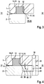
Fig. 3 eine erste erfindungsgemäße Ausführungsform der Gehäuseabdichtung in vereinfachter Schnittdarstellung. -
Fig. 4 eine zweite erfindungsgemäße Ausführungsform der Gehäuseabdichtung in vereinfachter Schnittdarstellung und -
Fig. 5 eine perspektivische Darstellung einer dritten erfindungsgemäßen Ausführungsform der Gehäuseabdichtung, veranschaulicht am Beispiel eines Gehäusedeckels. - Korrosionen an Dichtungsanordnungen werden im Bereich der vorgesehenen Dichtung durch deren Platzierung in meist konstruktiv tiefen und engen Spalten gefördert. Derartige Standard-Gehäuseabdichtungen bzw. Standard-Konstruktionen sind bekannt und in
Fig. 1 und Fig. 2 näher gezeigt. Dabei ist in einem inFig. 1 oben gezeigten Gehäuseteil 1 in einer Nut 10 eine umlaufende Dichtung 15 in Form eines axial verpressten O-Rings untergebracht. Die Nut 10 ist von einem zweiten unteren Gehäuseteil 2 abgedeckt. Zwischen einer ersten Dichtfläche 6 des ersten Gehäuseteils 1 und einer zweiten Dichtfläche 7 des zweiten Gehäuseteils liegt ein Fügespalt 20 vor. Außerdem liegt ein von der Dichtung 15 nicht ausgefüllter Nutraum 21 vor, der ebenfalls einen Spalt bildet. Rechts in denFiguren 1 bis 5 ist die korrosive Umgebung eines Gehäuseäußeren durch einen Pfeil 30 und ein gegenüberliegendes Gehäuseinneres durch das Bezugszeichen 31 gekennzeichnet. InFig. 2 ist die Anordnung vertikal ausgerichtet mit vertikal verlaufenden Dichtflächen 6, 7, die an einer Seite horizontal abknicken. Der O-Ring 15 ist dann entsprechend radial verpresst. Das zweite Gehäuseteil 2 ist an seiner oberen Seite teilweise vom ersten Gehäuseteil 1 aufgenommen, so dass insgesamt ein abgewinkelter, längerer Spaltverlauf 20 gegenüber dem inFig. 1 vorliegt. In denFiguren 1 und 2 sind das erste Gehäuseteil 1 aus Kunststoff und das zweite Gehäuseteil 2 aus Metall hergestellt. - In den Ausführungsformen nach
Figuren 1 und 2 stellt sich Korrosion im Bereich der Dichtung 15 ein. Ursächlich hierfür sind die Kapillarwirkung der Spalte 20 und des Nutraums 21, welche das korrosive Medium zur Dichtung 15 bzw. zur Dichtstelle führen. Dies führt zu einer verlangsamerten Abtrocknung in den Spalten 20 bzw. im Nutraum 21. Die Behinderung des Luft- bzw. Sauerstoffzutritts in den Spalten 20 bzw. in dem Nutraum 21 fördert die Spaltkorrosion. Bei weitverbreiteten Metallen, wie Aluminium und rostfreiem Stahl, ist der Sauerstoffzutritt weiterhin zur Korrosionsabwehr notwendig, um schützende Passivschichten bilden zu können. Als Folge der Behinderung des Luft- bzw. Sauerstoffzutritts ergibt sich eine weitere Verschärfung der Korrosionsbedingungen durch dann stattfindende Korrosionsreaktionen und einer Ansammlung von Korrosionsprodukten, zum Beispiel einer Chloridanreicherung und einer pH-Wert-Absenkung im Fügespalt 20. - Alle gleichen und gleichwirkenden Bauteile sind in den folgenden Ausführungsbeispielen mit denselben Bezugszeichen wie in den
Figuren 1 und 2 versehen. In derFig. 3 ist eine erste erfindungsgemäße Gehäuseabdichtung zweier Gehäuseteile 1, 2 mittels einer Dichtung 15 gezeigt. Ein oberes, erstes Gehäuseteil 1 liegt mit seiner oberen, ersten Dichtfläche 6 an einer unteren, zweiten Dichtfläche 7 eines unteren, zweiten Gehäuseteils 2 an. Das obere Gehäuseteil 1 weist in seiner oberen Dichtfläche 6 eine eingebrachte Nut 10 auf. In der Nut 10 ist eine Dichtung 15 mit eckigem, insbesondere quadratischem Querschnitt als sogenannte Schlauchabschnittsdichtung eingebracht. Möglich ist auch, eine Dichtung 15 mit einem rechteckförmigen Querschnitt in einer entsprechenden Nut vorzusehen. Möglich ist auch, die Dichtung 15 mit rundem Querschnitt wie in denFiguren 1 und 2 als sogenannte O-Ringdichtung auszubilden. Die Verwendung von Dichtungen mit eckigem Querschnitt hat den Vorteil, dass die Ausbildung eines umlaufenden Spalts, der durch die Auflage eines runden Dichtrings auf ebenen Dichtflächen entsteht, vermindert ist. Die erfindungsgemäße Gehäuseabdichtung ist aber auch bei Verwendung von O-Ringen mit rundem Querschnitt oder für Flüssigkeitsdichtungen vorteilhaft. Die Nut 10 wird von dem unteren Gehäuseteil 2 vollständig überdeckt. Erfindungsgemäß ist nun vorgesehen, dass die Nut 10 eine Öffnung 11 zwischen den Dichtflächen 6, 7 aufweist, welche zur Belüftung der Nut 10 bzw. des Nutraums 21 mit der Dichtung 15 dient. Die Öffnung 11 ist an einem Eckbereich einer dem Gehäuseäußern 30 zuwandten Innenwandung 12 zur unteren Dichtfläche 7 vorgesehen und bildet eine Verbindung zu einem Freibereich 35 im zweiten Gehäuseteil 2 bzw. direkt zur Umgebung. Der Freibereich 35 kann als umlaufende Materialaussparung 36 im zweiten Gehäuseteil 2 ausgeführt sein. Die Öffnung 11 kann radial entlang der Dichtung 15 verlaufen und bildet einen Schlitz 16 in der Nut 10 bzw. im Nutraum 21. Die zweite Dichtfläche 7 überragt die Nut 10 nur minimal und die Öffnung 11 wird durch eine abgebogene bzw. abgerundete bzw. eckige Gestaltung eines Dichtflächendends 17 der zweiten Dichtfläche 7 gebildet. - Wie die
Fig. 4 , ein zweites erfindungsgemäßes Ausführungsbeispiel, zeigt, kann der Freibereich 35 als Belüftungsnut 37 ausgeführt sein, welche zwischen der Nut 10 mit der Dichtung 15 und einer vorgesehenen Schraubverbindung 39 bzw. an Schraubaugen 38 der beiden Gehäuseteile 1, 2 verläuft. Durch die erfindungsgemäße Öffnung 11 zu einem Freiraum 35 bzw. zu einer Belüftungsnut 37 hin, werden die Abtrocknung und der Luftzutritt insbesondere im kritischen Bereich von vorgesehen Schraubaugen 38 erheblich verbessert, da kein Spalt mehr vorliegt bzw. ein unkritisches Maß vorliegt. Damit wird der Mechanismus der Spaltkorrosion nicht angeregt und eine weitere Verschärfung der Korrosionsbedingungen durch deren Folgeeffekte eines Spalts vermieden. Vorteilhafterweise wird durch die Öffnung 11 ein Kapillareffekt verhindert und auch der Zutritt von Flüssigkeit zum Dichtbereich reduziert, was auch bei Gehäuseteilen 1, 2 aus teilweise oder vollständigem Kunststoff Vorteile mit sich bringt. Die Öffnung 11 ist somit deutlich größer als ein möglicher Fügespalt auszuführen, um so den Kapillareffekt zu verhindern. Als vorteilhafte Öffnungsbreite b für die Öffnung hat sich dabei eine Größenordnung in einem Bereich von 0,5 bis 1 mm als wirksam herausgestellt. - Wie die
Fig. 5 , ein drittes Ausführungsbeispiel der erfindungsgemäßen Gehäuseabdichtung, zeigt, kann die Gehäuseabdichtung für einen Elektronik-Gehäusedeckel vorgesehen sein. Der Gehäusedeckel stellt dabei das erste Gehäuseteil 1 dar, welches mit dem zweiten, zylindrisch ausgeführten Gehäuseteil 2 zum Beispiel für Elektronikbauteile dicht verbunden ist. Erkennbar ist eine umlaufende Materialaussparung 36 gemäßFig. 3 , die im Bereich vorgesehener Schraubaugen 38 in Form einer Belüftungsnut 37 fortgeführt ist. Gestrichelt angedeutet ist die umlaufende Dichtung 15, welche mit rundem Querschnitt als O-Ringdichtung oder mit eckigem, insbesondere quadratischem Querschnitt als sogenannte Schlauchabschnittsdichtung ausgeführt sein kann. - Durch die erfindungsgemäße Gehäuseabdichtung werden tiefe, enge Spalte vermieden. Dies gewährleistet eine Reduzierung eines Zutritts von korrosivem Medium aus dem Gehäuseäußeren 30 zur Dichtung 15. Außerdem ist eine beschleunigte Abtrocknung und ein verbesserter Sauerstoffzutritt zu den Dichtflächen 6, 7, insbesondere zur Metalloberfläche der zweiten Dichtfläche 7 des zweiten Gehäuseteils 2 möglich. Damit kann das Auftreten von Dichtungsunterwanderung bzw. Spaltkorrosion verhindert werden. In den
Figuren 3 und 4 können das erste Gehäuseteil 1 aus Kunststoff und das zweite Gehäuseteil 2 aus Metall hergestellt sein. Möglich ist auch, beide Gehäuseteile 1, 2 komplett aus Metall oder komplett aus Kunststoff herzustellen. Da der Zutritt von Flüssigkeit zum Dichtbereich reduziert ist, ist die Erfindung auch bei Kunststoffoberflächen ohne Korrosion einsetzbar. - Die Erfindung ist für Wasserpumpen, insbesondere für Zusatzwasserpumpen von Kraftfahrzeugen, vorgesehen.
Claims (9)
- Gehäuseabdichtung zweier aneinanderliegender Gehäuseteile, eines ersten Gehäuseteils (1) mit einer ersten Dichtfläche (6) und eines zweiten Gehäuseteils (2) mit einer zweiten Dichtfläche (7), mit einer Dichtung, eingebracht in einer Nut in der ersten Dichtfläche des ersten Gehäuseteils, wobei die Nut von der zweiten Dichtfläche des zweiten Gehäuseteils überdeckt ist, wobei die Nut (10) eine Öffnung (11) zwischen den Dichtflächen (6, 7) aufweist, welche zur Belüftung der Nut (10) mit der eingebrachten Dichtung (15) dient, dadurch gekennzeichnet, dass die Öffnung (11) eine Öffnungsbreite (b) in einem Bereich von 0,5 bis 1 mm oder größer aufweist, wobei die Nut (10) von dem zweiten Gehäuseteil vollständig überdeckt ist, wobei die Öffnung (11) eine direkte Verbindung zu einem Freibereich (35) des zweiten Gehäuseteils (2) bzw. der Umgebung bildet, wobei die Öffnung (11) als Schlitz ausgebildet ist und wobei der Schlitz (16) radial entlang der Dichtung (15) verläuft.
- Gehäuseabdichtung nach Anspruch 1, dadurch gekennzeichnet, dass die zweite Dichtfläche (7) des zweiten Gehäuseteils (2) die Nut (10) nur minimal überragt und die Öffnung (11) durch eine abgebogene bzw. abgerundete Gestaltung eines Dichtflächenendes (17) der zweiten Dichtfläche (7) gebildet ist.
- Gehäuseabdichtung nach Anspruch 1 oder 2, dadurch gekennzeichnet, dass die Öffnung (11) zu einer am zweiten Gehäueteil (2) vorgesehenen Aussparung (36) im zweiten Gehäuseteil (2) führt.
- Gehäuseabdichtung nach Anspruch 3, dadurch gekennzeichnet, dass die Aussparung (36) im Bereich von Schraubaugen (38) einer Schraubverbindung (39) in Form einer Belüftungsnut (37) gestaltet ist.
- Gehäuseabdichtung nach einem der vorherigen Ansprüche 1 bis 4, dadurch gekennzeichnet, dass das die Öffnung (11) als Spalt (16) ausgebildet ist.
- Gehäuseabdichtung nach einem der vorherigen Ansprüche 1 bis 5, dadurch gekennzeichnet, dass die Dichtung (15) als O-Ringdichtung mit rundem Querschnitt ausgeführt ist.
- Gehäuseabdichtung nach einem der vorherigen Ansprüche 1 bis 6, dadurch gekennzeichnet, dass die Dichtung (15) einen eckigen, insbesondere quadratischen Querschnitt aufweist.
- Gehäuseabdichtung nach einem der vorherigen Ansprüche 1 bis 7, dadurch gekennzeichnet, dass zumindest ein Gehäuseteil (1; 2) zumindest teilweise aus Metall besteht.
- Gehäuseabdichtung nach einem der vorherigen Ansprüche 1 bis 8, dadurch gekennzeichnet, dass ein Gehäuseteil (1; 2) als Deckel ausgebildet ist.
Applications Claiming Priority (2)
| Application Number | Priority Date | Filing Date | Title |
|---|---|---|---|
| DE102012223354.7A DE102012223354A1 (de) | 2012-12-17 | 2012-12-17 | Gehäuseabdichtung zweier aneinanderliegender Gehäuseteile |
| PCT/EP2013/065712 WO2014095096A1 (de) | 2012-12-17 | 2013-07-25 | Gehäuseabdichtung zweier aneinanderliegender gehäuseteile |
Publications (2)
| Publication Number | Publication Date |
|---|---|
| EP2932810A1 EP2932810A1 (de) | 2015-10-21 |
| EP2932810B1 true EP2932810B1 (de) | 2017-09-06 |
Family
ID=48906238
Family Applications (1)
| Application Number | Title | Priority Date | Filing Date |
|---|---|---|---|
| EP13742616.9A Not-in-force EP2932810B1 (de) | 2012-12-17 | 2013-07-25 | Gehäuseabdichtung zweier aneinanderliegender gehäuseteile |
Country Status (6)
| Country | Link |
|---|---|
| US (1) | US9671022B2 (de) |
| EP (1) | EP2932810B1 (de) |
| CN (1) | CN104996004B (de) |
| DE (1) | DE102012223354A1 (de) |
| ES (1) | ES2651070T3 (de) |
| WO (1) | WO2014095096A1 (de) |
Cited By (1)
| Publication number | Priority date | Publication date | Assignee | Title |
|---|---|---|---|---|
| WO2026027458A1 (de) * | 2024-08-01 | 2026-02-05 | Zf Friedrichshafen Ag | Anordnung zur abdichtung eines spalts zwischen einem ersten bauteil und einem zweiten bauteil |
Families Citing this family (9)
| Publication number | Priority date | Publication date | Assignee | Title |
|---|---|---|---|---|
| CN105972421A (zh) * | 2016-07-20 | 2016-09-28 | 常州市恒泰源盛减速机配件厂 | 全方位无渗漏润滑油泵 |
| DE102017123354A1 (de) * | 2017-10-09 | 2019-04-11 | Zollner Elektronik Ag | Elektrische Baueinheit in Gehäuse aus unterschiedlichen Materialien |
| DE102020109895A1 (de) * | 2020-04-08 | 2021-10-14 | Elringklinger Ag | Gehäusedeckel und Verfahren zum Herstellen eines Gehäusedeckels |
| DE102020109893A1 (de) | 2020-04-08 | 2021-10-14 | Elringklinger Ag | Gehäusedeckel |
| DE102020207094A1 (de) | 2020-06-05 | 2021-12-09 | Volkswagen Aktiengesellschaft | Anordnung zweier Dichtpartner |
| DE102020127920A1 (de) | 2020-10-23 | 2022-04-28 | Audi Aktiengesellschaft | Anordnung zur Abdichtung eines Fügebereichs |
| JP7436411B2 (ja) * | 2021-03-01 | 2024-02-21 | 株式会社バルカー | シール構造 |
| CN118511022A (zh) * | 2022-01-31 | 2024-08-16 | 发那科株式会社 | 密封结构 |
| DE102022121501A1 (de) * | 2022-08-25 | 2024-03-07 | Bayerische Motoren Werke Aktiengesellschaft | Vorrichtung zum Entfernen von sich in einem Dichtsystem an Schnittstellen von Elektronikgehäusen in einem Kraftfahrzeug befindender Flüssigkeit |
Family Cites Families (8)
| Publication number | Priority date | Publication date | Assignee | Title |
|---|---|---|---|---|
| US4699292A (en) * | 1986-08-20 | 1987-10-13 | Westvaco Corporation | Pulp bleaching tower pressure relief hatch |
| US5197766A (en) * | 1991-10-28 | 1993-03-30 | General Electric Company | Fluid-carrying tube coupling assembly with internal seal and drain arrangement |
| GB9124386D0 (en) | 1991-11-16 | 1992-01-08 | Bowthorpe Holdings Plc | Cable jointing enclosure |
| AUPM483194A0 (en) * | 1994-03-31 | 1994-04-28 | Hodgins, Sydney Gilbert | Seals |
| DE19628731A1 (de) * | 1996-07-17 | 1998-01-22 | Schloemann Siemag Ag | Abgedichtetes Walzenlager |
| JP4402526B2 (ja) * | 2004-06-22 | 2010-01-20 | シンクレイヤ株式会社 | 電気機器の筐体 |
| CN101865049A (zh) * | 2010-05-21 | 2010-10-20 | 隆鑫工业有限公司 | 曲轴箱合箱面密封结构 |
| DE102010042137A1 (de) | 2010-10-07 | 2012-04-12 | Robert Bosch Gmbh | Abdichtung zwischen Gehäuseteilen |
-
2012
- 2012-12-17 DE DE102012223354.7A patent/DE102012223354A1/de not_active Withdrawn
-
2013
- 2013-07-25 CN CN201380065826.XA patent/CN104996004B/zh not_active Expired - Fee Related
- 2013-07-25 WO PCT/EP2013/065712 patent/WO2014095096A1/de not_active Ceased
- 2013-07-25 EP EP13742616.9A patent/EP2932810B1/de not_active Not-in-force
- 2013-07-25 ES ES13742616.9T patent/ES2651070T3/es active Active
- 2013-07-25 US US14/652,993 patent/US9671022B2/en not_active Expired - Fee Related
Non-Patent Citations (1)
| Title |
|---|
| None * |
Cited By (1)
| Publication number | Priority date | Publication date | Assignee | Title |
|---|---|---|---|---|
| WO2026027458A1 (de) * | 2024-08-01 | 2026-02-05 | Zf Friedrichshafen Ag | Anordnung zur abdichtung eines spalts zwischen einem ersten bauteil und einem zweiten bauteil |
Also Published As
| Publication number | Publication date |
|---|---|
| ES2651070T3 (es) | 2018-01-24 |
| CN104996004A (zh) | 2015-10-21 |
| EP2932810A1 (de) | 2015-10-21 |
| CN104996004B (zh) | 2018-11-20 |
| US9671022B2 (en) | 2017-06-06 |
| WO2014095096A1 (de) | 2014-06-26 |
| DE102012223354A1 (de) | 2014-06-18 |
| US20150337962A1 (en) | 2015-11-26 |
Similar Documents
| Publication | Publication Date | Title |
|---|---|---|
| WO2014095096A1 (de) | Gehäuseabdichtung zweier aneinanderliegender gehäuseteile | |
| DE102019131441B3 (de) | Elektronikgehäuse zur Aufnahme einer elektrischen Komponente | |
| WO2017102630A1 (de) | Elektrische antriebseinheit mit einem gehäuse | |
| EP3120442B1 (de) | Elektromotor, insbesondere aussenläufermotor, sowie zwischenisolierteil für einen elektromotor | |
| DE202010007769U1 (de) | Elektrisch leitende Schraubverbindung und Spezialschraube für eine solche Schraubverbindung | |
| EP2980923B1 (de) | Automatisierungsbaugruppe für die industrielle Prozessautomatisierung | |
| DE102014218528A1 (de) | Gehäuse zur Aufnahme elektrischer und/oder elektronischer Bauteile, elektronisches Steuergerät und Verfahren zur Herstellung derselben | |
| DE102019214751A1 (de) | Gehäuse | |
| EP2009292B1 (de) | Pneumatikzylinder mit einem Zylindergehäuse aus stranggepresstem Metall | |
| DE102019131152A1 (de) | Batteriegehäuse | |
| EP3345466B1 (de) | Gehäusedichtungsanordnung | |
| DE102013201790B4 (de) | Gehäuse mit Schutzvorrichtung für eine Nassdichtung | |
| EP3566271B1 (de) | Schaltschranktür für ein schaltschrankgehäuse | |
| DE102012006786B4 (de) | Vorrichtung zum Durchführen eines Stranges durch ein Blech | |
| DE102024200093A1 (de) | Dichtungsanordnung | |
| DE202012104745U1 (de) | Durchführungsanordnung für ein Kabel | |
| DE102012206626B4 (de) | Trägerrahmendichtung mit verringertem Platzbedarf | |
| DE102015016365A1 (de) | Schraube | |
| EP3648318B1 (de) | Magnethalter, sensormagnetbaugruppe, elektromotor mit einer sensormagnetbaugruppe und verfahren zur herstellung einer sensormagnetbaugruppe | |
| DE102016107880A1 (de) | Schraubverbindung | |
| DE102017212558A1 (de) | Erdungsvorrichtung für Fahrzeuge | |
| DE102012014779A1 (de) | Gewindeelement, insbesondere Schraube, sowie Verbindungsanordnung mit einem solchen Gewindeelement | |
| DE102018114964A1 (de) | Gehäuse und Herstellungsverfahren hierfür | |
| EP1666776B1 (de) | Zylinderkopfdichtung mit einem Abschirmabschnitt | |
| EP3560306B1 (de) | Transmittergehäuse mit deckel und deckelsicherung |
Legal Events
| Date | Code | Title | Description |
|---|---|---|---|
| PUAI | Public reference made under article 153(3) epc to a published international application that has entered the european phase |
Free format text: ORIGINAL CODE: 0009012 |
|
| 17P | Request for examination filed |
Effective date: 20150717 |
|
| AK | Designated contracting states |
Kind code of ref document: A1 Designated state(s): AL AT BE BG CH CY CZ DE DK EE ES FI FR GB GR HR HU IE IS IT LI LT LU LV MC MK MT NL NO PL PT RO RS SE SI SK SM TR |
|
| AX | Request for extension of the european patent |
Extension state: BA ME |
|
| DAX | Request for extension of the european patent (deleted) | ||
| GRAP | Despatch of communication of intention to grant a patent |
Free format text: ORIGINAL CODE: EPIDOSNIGR1 |
|
| INTG | Intention to grant announced |
Effective date: 20161213 |
|
| GRAJ | Information related to disapproval of communication of intention to grant by the applicant or resumption of examination proceedings by the epo deleted |
Free format text: ORIGINAL CODE: EPIDOSDIGR1 |
|
| GRAJ | Information related to disapproval of communication of intention to grant by the applicant or resumption of examination proceedings by the epo deleted |
Free format text: ORIGINAL CODE: EPIDOSDIGR1 |
|
| GRAP | Despatch of communication of intention to grant a patent |
Free format text: ORIGINAL CODE: EPIDOSNIGR1 |
|
| GRAJ | Information related to disapproval of communication of intention to grant by the applicant or resumption of examination proceedings by the epo deleted |
Free format text: ORIGINAL CODE: EPIDOSDIGR1 |
|
| GRAP | Despatch of communication of intention to grant a patent |
Free format text: ORIGINAL CODE: EPIDOSNIGR1 |
|
| INTC | Intention to grant announced (deleted) | ||
| GRAJ | Information related to disapproval of communication of intention to grant by the applicant or resumption of examination proceedings by the epo deleted |
Free format text: ORIGINAL CODE: EPIDOSDIGR1 |
|
| INTG | Intention to grant announced |
Effective date: 20170329 |
|
| GRAP | Despatch of communication of intention to grant a patent |
Free format text: ORIGINAL CODE: EPIDOSNIGR1 |
|
| INTG | Intention to grant announced |
Effective date: 20170508 |
|
| GRAS | Grant fee paid |
Free format text: ORIGINAL CODE: EPIDOSNIGR3 |
|
| GRAA | (expected) grant |
Free format text: ORIGINAL CODE: 0009210 |
|
| AK | Designated contracting states |
Kind code of ref document: B1 Designated state(s): AL AT BE BG CH CY CZ DE DK EE ES FI FR GB GR HR HU IE IS IT LI LT LU LV MC MK MT NL NO PL PT RO RS SE SI SK SM TR |
|
| REG | Reference to a national code |
Ref country code: GB Ref legal event code: FG4D Free format text: NOT ENGLISH |
|
| REG | Reference to a national code |
Ref country code: CH Ref legal event code: EP Ref country code: AT Ref legal event code: REF Ref document number: 927222 Country of ref document: AT Kind code of ref document: T Effective date: 20170915 |
|
| REG | Reference to a national code |
Ref country code: IE Ref legal event code: FG4D Free format text: LANGUAGE OF EP DOCUMENT: GERMAN |
|
| REG | Reference to a national code |
Ref country code: DE Ref legal event code: R096 Ref document number: 502013008297 Country of ref document: DE |
|
| REG | Reference to a national code |
Ref country code: NL Ref legal event code: MP Effective date: 20170906 |
|
| REG | Reference to a national code |
Ref country code: ES Ref legal event code: FG2A Ref document number: 2651070 Country of ref document: ES Kind code of ref document: T3 Effective date: 20180124 |
|
| REG | Reference to a national code |
Ref country code: LT Ref legal event code: MG4D |
|
| PG25 | Lapsed in a contracting state [announced via postgrant information from national office to epo] |
Ref country code: LT Free format text: LAPSE BECAUSE OF FAILURE TO SUBMIT A TRANSLATION OF THE DESCRIPTION OR TO PAY THE FEE WITHIN THE PRESCRIBED TIME-LIMIT Effective date: 20170906 Ref country code: NO Free format text: LAPSE BECAUSE OF FAILURE TO SUBMIT A TRANSLATION OF THE DESCRIPTION OR TO PAY THE FEE WITHIN THE PRESCRIBED TIME-LIMIT Effective date: 20171206 Ref country code: SE Free format text: LAPSE BECAUSE OF FAILURE TO SUBMIT A TRANSLATION OF THE DESCRIPTION OR TO PAY THE FEE WITHIN THE PRESCRIBED TIME-LIMIT Effective date: 20170906 Ref country code: FI Free format text: LAPSE BECAUSE OF FAILURE TO SUBMIT A TRANSLATION OF THE DESCRIPTION OR TO PAY THE FEE WITHIN THE PRESCRIBED TIME-LIMIT Effective date: 20170906 Ref country code: HR Free format text: LAPSE BECAUSE OF FAILURE TO SUBMIT A TRANSLATION OF THE DESCRIPTION OR TO PAY THE FEE WITHIN THE PRESCRIBED TIME-LIMIT Effective date: 20170906 |
|
| PG25 | Lapsed in a contracting state [announced via postgrant information from national office to epo] |
Ref country code: RS Free format text: LAPSE BECAUSE OF FAILURE TO SUBMIT A TRANSLATION OF THE DESCRIPTION OR TO PAY THE FEE WITHIN THE PRESCRIBED TIME-LIMIT Effective date: 20170906 Ref country code: BG Free format text: LAPSE BECAUSE OF FAILURE TO SUBMIT A TRANSLATION OF THE DESCRIPTION OR TO PAY THE FEE WITHIN THE PRESCRIBED TIME-LIMIT Effective date: 20171206 Ref country code: GR Free format text: LAPSE BECAUSE OF FAILURE TO SUBMIT A TRANSLATION OF THE DESCRIPTION OR TO PAY THE FEE WITHIN THE PRESCRIBED TIME-LIMIT Effective date: 20171207 Ref country code: LV Free format text: LAPSE BECAUSE OF FAILURE TO SUBMIT A TRANSLATION OF THE DESCRIPTION OR TO PAY THE FEE WITHIN THE PRESCRIBED TIME-LIMIT Effective date: 20170906 |
|
| PG25 | Lapsed in a contracting state [announced via postgrant information from national office to epo] |
Ref country code: NL Free format text: LAPSE BECAUSE OF FAILURE TO SUBMIT A TRANSLATION OF THE DESCRIPTION OR TO PAY THE FEE WITHIN THE PRESCRIBED TIME-LIMIT Effective date: 20170906 |
|
| PG25 | Lapsed in a contracting state [announced via postgrant information from national office to epo] |
Ref country code: PL Free format text: LAPSE BECAUSE OF FAILURE TO SUBMIT A TRANSLATION OF THE DESCRIPTION OR TO PAY THE FEE WITHIN THE PRESCRIBED TIME-LIMIT Effective date: 20170906 Ref country code: RO Free format text: LAPSE BECAUSE OF FAILURE TO SUBMIT A TRANSLATION OF THE DESCRIPTION OR TO PAY THE FEE WITHIN THE PRESCRIBED TIME-LIMIT Effective date: 20170906 |
|
| PG25 | Lapsed in a contracting state [announced via postgrant information from national office to epo] |
Ref country code: SM Free format text: LAPSE BECAUSE OF FAILURE TO SUBMIT A TRANSLATION OF THE DESCRIPTION OR TO PAY THE FEE WITHIN THE PRESCRIBED TIME-LIMIT Effective date: 20170906 Ref country code: SK Free format text: LAPSE BECAUSE OF FAILURE TO SUBMIT A TRANSLATION OF THE DESCRIPTION OR TO PAY THE FEE WITHIN THE PRESCRIBED TIME-LIMIT Effective date: 20170906 Ref country code: EE Free format text: LAPSE BECAUSE OF FAILURE TO SUBMIT A TRANSLATION OF THE DESCRIPTION OR TO PAY THE FEE WITHIN THE PRESCRIBED TIME-LIMIT Effective date: 20170906 Ref country code: IS Free format text: LAPSE BECAUSE OF FAILURE TO SUBMIT A TRANSLATION OF THE DESCRIPTION OR TO PAY THE FEE WITHIN THE PRESCRIBED TIME-LIMIT Effective date: 20180106 |
|
| REG | Reference to a national code |
Ref country code: DE Ref legal event code: R097 Ref document number: 502013008297 Country of ref document: DE |
|
| PLBE | No opposition filed within time limit |
Free format text: ORIGINAL CODE: 0009261 |
|
| STAA | Information on the status of an ep patent application or granted ep patent |
Free format text: STATUS: NO OPPOSITION FILED WITHIN TIME LIMIT |
|
| REG | Reference to a national code |
Ref country code: FR Ref legal event code: PLFP Year of fee payment: 6 |
|
| PG25 | Lapsed in a contracting state [announced via postgrant information from national office to epo] |
Ref country code: DK Free format text: LAPSE BECAUSE OF FAILURE TO SUBMIT A TRANSLATION OF THE DESCRIPTION OR TO PAY THE FEE WITHIN THE PRESCRIBED TIME-LIMIT Effective date: 20170906 |
|
| 26N | No opposition filed |
Effective date: 20180607 |
|
| PG25 | Lapsed in a contracting state [announced via postgrant information from national office to epo] |
Ref country code: SI Free format text: LAPSE BECAUSE OF FAILURE TO SUBMIT A TRANSLATION OF THE DESCRIPTION OR TO PAY THE FEE WITHIN THE PRESCRIBED TIME-LIMIT Effective date: 20170906 |
|
| PG25 | Lapsed in a contracting state [announced via postgrant information from national office to epo] |
Ref country code: MT Free format text: LAPSE BECAUSE OF FAILURE TO SUBMIT A TRANSLATION OF THE DESCRIPTION OR TO PAY THE FEE WITHIN THE PRESCRIBED TIME-LIMIT Effective date: 20170906 |
|
| REG | Reference to a national code |
Ref country code: CH Ref legal event code: PL |
|
| GBPC | Gb: european patent ceased through non-payment of renewal fee |
Effective date: 20180725 |
|
| PG25 | Lapsed in a contracting state [announced via postgrant information from national office to epo] |
Ref country code: LU Free format text: LAPSE BECAUSE OF NON-PAYMENT OF DUE FEES Effective date: 20180725 Ref country code: MC Free format text: LAPSE BECAUSE OF FAILURE TO SUBMIT A TRANSLATION OF THE DESCRIPTION OR TO PAY THE FEE WITHIN THE PRESCRIBED TIME-LIMIT Effective date: 20170906 |
|
| REG | Reference to a national code |
Ref country code: BE Ref legal event code: MM Effective date: 20180731 |
|
| REG | Reference to a national code |
Ref country code: IE Ref legal event code: MM4A |
|
| PG25 | Lapsed in a contracting state [announced via postgrant information from national office to epo] |
Ref country code: LI Free format text: LAPSE BECAUSE OF NON-PAYMENT OF DUE FEES Effective date: 20180731 Ref country code: CH Free format text: LAPSE BECAUSE OF NON-PAYMENT OF DUE FEES Effective date: 20180731 Ref country code: GB Free format text: LAPSE BECAUSE OF NON-PAYMENT OF DUE FEES Effective date: 20180725 Ref country code: IE Free format text: LAPSE BECAUSE OF NON-PAYMENT OF DUE FEES Effective date: 20180725 |
|
| PG25 | Lapsed in a contracting state [announced via postgrant information from national office to epo] |
Ref country code: BE Free format text: LAPSE BECAUSE OF NON-PAYMENT OF DUE FEES Effective date: 20180731 |
|
| REG | Reference to a national code |
Ref country code: AT Ref legal event code: MM01 Ref document number: 927222 Country of ref document: AT Kind code of ref document: T Effective date: 20180725 |
|
| PG25 | Lapsed in a contracting state [announced via postgrant information from national office to epo] |
Ref country code: AT Free format text: LAPSE BECAUSE OF NON-PAYMENT OF DUE FEES Effective date: 20180725 |
|
| PG25 | Lapsed in a contracting state [announced via postgrant information from national office to epo] |
Ref country code: TR Free format text: LAPSE BECAUSE OF FAILURE TO SUBMIT A TRANSLATION OF THE DESCRIPTION OR TO PAY THE FEE WITHIN THE PRESCRIBED TIME-LIMIT Effective date: 20170906 |
|
| PG25 | Lapsed in a contracting state [announced via postgrant information from national office to epo] |
Ref country code: PT Free format text: LAPSE BECAUSE OF FAILURE TO SUBMIT A TRANSLATION OF THE DESCRIPTION OR TO PAY THE FEE WITHIN THE PRESCRIBED TIME-LIMIT Effective date: 20170906 |
|
| PG25 | Lapsed in a contracting state [announced via postgrant information from national office to epo] |
Ref country code: HU Free format text: LAPSE BECAUSE OF FAILURE TO SUBMIT A TRANSLATION OF THE DESCRIPTION OR TO PAY THE FEE WITHIN THE PRESCRIBED TIME-LIMIT; INVALID AB INITIO Effective date: 20130725 Ref country code: MK Free format text: LAPSE BECAUSE OF NON-PAYMENT OF DUE FEES Effective date: 20170906 Ref country code: CY Free format text: LAPSE BECAUSE OF FAILURE TO SUBMIT A TRANSLATION OF THE DESCRIPTION OR TO PAY THE FEE WITHIN THE PRESCRIBED TIME-LIMIT Effective date: 20170906 |
|
| PG25 | Lapsed in a contracting state [announced via postgrant information from national office to epo] |
Ref country code: AL Free format text: LAPSE BECAUSE OF FAILURE TO SUBMIT A TRANSLATION OF THE DESCRIPTION OR TO PAY THE FEE WITHIN THE PRESCRIBED TIME-LIMIT Effective date: 20170906 |
|
| PGFP | Annual fee paid to national office [announced via postgrant information from national office to epo] |
Ref country code: FR Payment date: 20200727 Year of fee payment: 8 Ref country code: CZ Payment date: 20200722 Year of fee payment: 8 Ref country code: ES Payment date: 20200818 Year of fee payment: 8 |
|
| PGFP | Annual fee paid to national office [announced via postgrant information from national office to epo] |
Ref country code: IT Payment date: 20200731 Year of fee payment: 8 |
|
| PG25 | Lapsed in a contracting state [announced via postgrant information from national office to epo] |
Ref country code: FR Free format text: LAPSE BECAUSE OF NON-PAYMENT OF DUE FEES Effective date: 20210731 Ref country code: CZ Free format text: LAPSE BECAUSE OF NON-PAYMENT OF DUE FEES Effective date: 20210725 |
|
| PG25 | Lapsed in a contracting state [announced via postgrant information from national office to epo] |
Ref country code: IT Free format text: LAPSE BECAUSE OF NON-PAYMENT OF DUE FEES Effective date: 20210725 |
|
| REG | Reference to a national code |
Ref country code: ES Ref legal event code: FD2A Effective date: 20221005 |
|
| PG25 | Lapsed in a contracting state [announced via postgrant information from national office to epo] |
Ref country code: ES Free format text: LAPSE BECAUSE OF NON-PAYMENT OF DUE FEES Effective date: 20210726 |
|
| PGFP | Annual fee paid to national office [announced via postgrant information from national office to epo] |
Ref country code: DE Payment date: 20230922 Year of fee payment: 11 |
|
| REG | Reference to a national code |
Ref country code: DE Ref legal event code: R119 Ref document number: 502013008297 Country of ref document: DE |
|
| PG25 | Lapsed in a contracting state [announced via postgrant information from national office to epo] |
Ref country code: DE Free format text: LAPSE BECAUSE OF NON-PAYMENT OF DUE FEES Effective date: 20250201 |